倍加福安全栅KFD2-STC5-Ex2模拟量输入安全栅介绍
MTL安全栅

端子功能
K-P
KONZERN-PRODUKTION
汇报人:胡超 热工维修 Stand: 09.09.2012| Seite 4
技术参数
1.通路数 单通路,带两个可组态报警
2.安全区输出 二个继电器带转换点
3.危险区输出 信号范围:0至24mA(含超出范围)
4.给变送器的电压(端子1,2) 20mA时,>17V
安全栅
K-P
KONZERN-PRODUKTION
汇报人:胡超 热工维修 Stand: 09.09.2012| Seite 1
MTL公司
安全栅简介
安全栅又称安全保持器。 本安回路的安全接口,它 能在安全区和危险区之间 双向转递电信号,并可限 制因故障引起的安全区向 危险区和能量转递。一般 安全栅有齐纳式、隔离式.
由于安全栅被设计为介于 现场设备与控制室设备之 间的一个限制能量的接口, 因此无论控制室设备处于 正常或故障状态,安全栅 都能确保通过它传送给现 场设备的能量是本质安全 的
现场使用的RODUKTION
汇报人:胡超 热工维修 Stand: 09.09.2012| Seite 2
5电流输入(端子1至3) 最大输入电阻25Ω
6.响应时间 <75ms
7.发光二极管显示
绿色:电源显示,组件得电时电亮
黄色:每个报警点一个,继电器激励时(没有被报警)点亮。
8.安全描述
端子2至1和3 28V,300Ω,93mA
端子1至3
无能量储存设备≤1.2V,≤0.1A可与任何开路电
K-P
KONZERN-PRODUKTION
压<28V的本安回路相连。
汇报人:胡超 热工维修 Stand: 09.09.2012| Seite 5
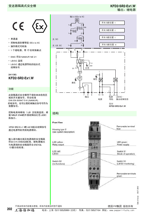
KFD2-SR2-Ex1.W中文
机械构造 外形尺寸 重量
KFD2-SR2-Ex1.W
符合IEC 60947-5-6 (NAMUR, DIN 19234),见系统说明的电气参数 符合 DIN EN 50178 符合 DIN EN 50178 符合 DIN IEC 721 符合 EN 50081-2/EN 50082-2, NAMUR NE 21
I II S1
S3 红色
&
+-
绿色 黄色
7 89 输出
14 15 电源
+-
电源 LB/SC 导轨 集合故障信息
仅对 KFD2-SR2-Ex1.W
KFD2-SR2-Ex1.W的LB/SC组合故障信号 通过电源导轨传到电源模块。
输入端与输出端及电源端的安全隔离 符合DIN EN50020标准。继电器输出 与电源端的安全隔离符合EN0106, 101部分的标准。
-20 ... 60 °C (253 ... 333 K)
20 x 118 x 115 mm (0.78 x 4.6 x 4.5 inch) 约. 150 g
电源导轨 PR 02 电源导轨 UPR 02 电源模块 KFD2-EB2 电源模块通过电源导轨PR 02或UPR 02提供24VDC电压并同步
IIC 2.41 µF 210 mH
J.I.3002773 No. 116-0035 是 端子 1, 3; 2, 3; 4, 6; 5, 6
12.9 V 19.8 mA A&B 1.273 µF 84.8 mH
C&E 3.82 µF 254.4 mH
D, F&G 10.18 µF 678.4 mH
E 106378 LR 36087-13 No. 116-0047 端子 1, 3; 2, 3; 4, 6; 5, 6
KFD2-STC4-Ex1.2O 智能传输器电源隔离屏障说明书

SMART Transmitter Power SupplyKFD2-STC4-Ex1.2O<1-channel isolated barrier<24 V DC supply (Power Rail)<Input 2-wire and 3-wire SMART transmitters and 2-wire SMARTcurrent sources<Signal splitter (1 input and 2 outputs)<Dual output 0/4 mA ... 20 mA<Terminal blocks with test sockets<Up to SIL 3 acc. to IEC 615083 Input 0/4 mA ... 20 mA2 x Output 0/4 mA ... 20 mAThis isolated barrier is used for intrinsic safety applications.The device supplies 2-wire and 3-wire SMART transmitters in a hazardous area, and can also be used with 2-wire SMART current sources.It transfers the analog input signal to the safe area as an isolated current value.Digital signals may be superimposed on the input signal in the hazardous or safe area and are transferred bi-directionally.If the HART communication resistance in the loop is too low, the internal resistance of 250 Ω between terminals 8 and 9 can be used.Test sockets for the connection of HART communicators are integrated into the terminals of the device.Zone 2Div. 235-6+1+2--24 V DC14+15-IIIedate:22-9-23Dateofissue:22-9-23Filename:283674_eng.pdfe d a t e : 2020-09-23 D a t e of i s s u e : 2020-09-23 F i l e n a m e : 283674_e ng .p d fe d a t e : 2020-09-23 D a t e of i s s u e : 2020-09-23 F i l e n a m e : 283674_e ng .p d fFront viewe d a t e : 2020-09-23 D a t e of i s s u e : 2020-09-23 F i l e n a m e : 283674_e ng .p d fe d a t e : 2020-09-23 D a t e of i s s u e : 2020-09-23 F i l e n a m e : 283674_e ng .p d fKFD2-STC4-Ex1.2OSMART Transmitter Power Supply The device supports the following SMART protocols:•HART •BRAIN •FoxboroConfiguration active output (source)If only one output of the two outputs is used, a plug-in jumper have to be set as follows.7-8+910-11+12I。
安全栅基础知识

安全栅基础知识目录一、基本概念 (2)1.1 安全栅的定义 (3)1.2 安全栅的作用 (4)二、工作原理 (4)2.1 电气隔离原理 (5)2.2 信号处理原理 (6)三、类型与结构 (7)3.1 一拖一安全栅 (8)3.2 一拖二安全栅 (9)3.3 四遥安全栅 (10)四、选型与配置 (12)4.1 选择依据 (13)4.2 配置步骤 (14)五、安装与调试 (16)5.1 安装要求 (16)5.2 调试方法 (17)六、维护与故障排除 (18)6.1 日常检查 (19)6.2 常见故障及处理 (20)七、安全规范与标准 (20)7.1 国家标准 (22)7.2 行业标准 (22)八、应用案例 (24)8.1 工业自动化领域 (25)8.2 电力系统领域 (26)九、发展趋势与展望 (27)9.1 技术创新方向 (28)9.2 市场前景分析 (29)一、基本概念也被称为安全隔离栅或者安全防护栅,在现代社会的工业、商业和家庭环境中扮演着重要的安全防护角色。
它是一种特定的设备或系统,用于阻止未经授权的人员或物体进入特定区域,同时允许授权人员安全、方便地通过。
安全栅的主要目的是确保特定区域的安全性和隐私性,防止潜在的风险和危险。
定义与功能:安全栅是一种物理障碍,用于隔离和划分区域,确保只有授权的人员和物体能够进入特定区域。
它通常配备有门禁系统、报警装置和监控设备等,以增强安全性和监控能力。
类型与结构:根据不同的应用场景和需求,安全栅有多种类型和结构。
常见的有围栏式安全栅、通道式安全栅、道路安全栅等。
它们可以是固定的也可以是移动的,可以是电子控制的也可以是机械控制的。
安全性与可靠性:安全栅的核心是其安全性和可靠性。
其设计需符合相关的安全标准,如防火、防撞击、防攀爬等,确保无法轻易被非法入侵。
安全栅还需配备报警系统和监控设备,能够在非法入侵发生时及时发出警报并通知相关人员。
应用场景:安全栅广泛应用于工业厂区、军事设施、监狱、住宅小区、公共设施等需要高度安全保障的场所。
隔离式安全栅 HD5500 系列产品选型手册说明书

SIHD5-PTCH-00B1隔离式安全栅HD5500系列产品选型手册概 述电气隔离技术能够实现输入/输出信号的完全隔离,从而显著提升电子系统的抗干扰性和可靠性,越来越多的工业控制对现场设备和控制室设备之间提出了采用隔离接口单元的要求。
HD5500系列隔离式安全栅通过光、电、磁等隔离技术对供电电源、输入端信号和输出端信号进行相互隔离,从而实现现场的本质安全设备和控制室设备之间数字/模拟信号的隔离传输,是现场的本质安全设备和控制室设备之间理想的隔离接口单元。
HD5500系列隔离式安全栅的设计遵循最新的国家标准GB3836.1-2010、GB3836.4-2010,符合本质安全防爆要求,具备严格的隔离及能量限制能力,可与安装在危险场所的本质安全设备共同组成本质安全防爆系统,通过内部综合性的限压、限流设计来限制流向危险区的电能量,从而保证危险场所的电器设备及人身安全。
HD5500全系列隔离式安全栅涵盖了以下设备功能:热电阻温度信号变送器、热电偶温度信号变送器、毫伏信号变送器、配电器、信号分配器以及中间驱动继电器等。
特 点∙ [Ex ia Ga]ⅡC 防爆等级,适用于最危险的0区危险场所及最危险介质。
∙ 隔离故障点,将调试维护过程中可能出现的故障限制在单侧,即使遭受如雷击等意外。
∙ 输入/输出信号及电源三端口隔离,构成完全浮空的系统,从而消除工业现场复杂的工频干扰、共模干扰等影响,极大地简化现场问题的处理。
∙ 三重冗余电路设计。
∙ 完善的线路故障指示,便于现场故障点的快速定位、查找。
∙ 无须接地,相关现场设备可视情况接地或不接地,消除接地回路带来的干扰。
∙ 低功耗及有效的散热结构设计,有效地降低密集安装条件下机柜的温升,提高产品可靠性,延长使用寿命。
∙ 高转换精度。
∙ 功能系列化,可满足信号隔离、配电、信号变送等过程控制中最广泛的功能需求。
∙ 12.5mm 超薄设计,顺应现代控制密集安装要求,节省机柜空间,提高装置的集成度。
Pepperl+Fuchs SMART传输器电源KFD2-STC4-Ex1.ES说明书

17-08-09 14:38D a t e o f i s s u e 2017-08-10227919_e n g .x m lConnectionAssembly•1-channel isolated barrier •24 V DC supply (Power Rail)•Input for 2-wire SMART transmitters and current sources •Output for 4 mA ... 20 mA or 1 V ... 5 V •Sink or source mode•Line fault detection (LFD)•Up to SIL3 acc.to IEC 61508FunctionThis isolated barrier is used for intrinsic safety applications.The device supplies 2-wire transmitters in the hazardous area, and can also be used with current sources.It transfers the analog input signal to the safe area as an isolated current value.Bi-directional communication is supported forSMART transmitters that use current modulation to transmit data and voltage modulation to receive data.The output is selected as a current source, current sink, or voltage source via DIP switches.A fault is signalized by LEDs acc. to NAMUR NE44 and a separate collective error message output.Test sockets for the connection of HART communicators are integrated into the terminals of the device.ApplicationThe device supports the following SMART protocol:•HART3Features17-08-09 14:38D a t e o f i s s u e 2017-08-10227919_e n g .x mlGeneral specifications Signal typeAnalog inputFunctional safety related parameters Safety Integrity Level (SIL) SIL 3Supply Connection Power Rail or terminals 14+, 15-Rated voltage U r 19 ... 30 V DC Ripple ≤ 10 %Rated current I r≤ 50 mA Power dissipation ≤ 800 mW Power consumption ≤ 1.2 W InputConnection side field sideConnection terminals 1+, 3-; 6+, 5-Input signal 4 ... 20 mA , limited to approx. 27 mA reverse polarity protected Line fault detection downscaling ≤ 3 mA ; upscaling ≥ 22 mA Voltage drop approx. 5 V on terminals 5-, 6+Available voltage ≥ 15 V at 20 mA terminals 1+, 3-OutputConnection side control side Connection terminals 7-, 8+Load 0 ... 300 Ω (source mode)Output signal4 ... 20 mA or 1 ...5 V (on 250 Ω, 0.1 % internal shunt) 4 ... 20 mA (sink mode), operating voltage 16 ... 28 V Ripple 20 mV rms Fault indication output Output typefault bus signal , open collector transistorTransfer characteristics Deviationat 20 °C (68 °F)≤ ± 20 µA incl. calibration, linearity, hysteresis, loads and supply voltage fluctuations (source mode and sink mode 4 ... 20 mA)≤ 10 mV incl. calibration, linearity, hysteresis and fluctuations of supply voltage (source mode 1 ... 5 V)Influence of ambient temperature< 2 µA/K (0 ... 70 °C (32 ... 158 °F)); < 4 µA/K (-20 ... 0 °C (-4 ... 32 °F)) (source mode and sink mode 4 ... 20 mA)< 0.5 mV/K (0 ... 70 °C (32 ... 158 °F)); < 1 mV/K (-20 ... 0 °C (-4 ... 32 °F)) (source mode 1 ... 5 V)Frequency range field side into the control side: bandwidth with 1 mA pp signal 0 ... 3 kHz (-3 dB) control side into the field side: bandwidth with 0.5 V pp signal 0 ... 3 kHz (-3 dB)Settling time ≤ 200 ms Rise time/fall time ≤ 20 msGalvanic isolation Input/Output safe electrical isolation acc. to IEC/EN 60079-11, voltage peak value 375 V Input/power supply safe electrical isolation acc. to IEC/EN 60079-11, voltage peak value 375 V Output/power supply Basic isolation acc. to EN 61010-1 rated insulation voltage ≤ 50 V Indicators/settings Display elements LEDs Control elements DIP-switchConfiguration via DIP switches Labelingspace for labeling at the front Directive conformity Electromagnetic compatibilityDirective 2014/30/EU EN 61326-1:2013 (industrial locations)ConformityElectromagnetic compatibility NE 21:2006Degree of protection IEC 60529:2001Ambient conditions Ambient temperature -20 ... 70 °C (-4 ... 158 °F)Mechanical specifications Degree of protection IP20Connection screw terminalsMass approx. 150 gDimensions 20 x 124 x 115 mm (0.8 x 4.9 x 4.5 inch) , housing type B2Mountingon 35 mm DIN mounting rail acc. to EN 60715:2001Data for application in connection17-08-09 14:38D a t e o f i s s u e 2017-08-10227919_e n g .x mlInputEx ia, Ex iaDSupplyMaximum safe voltage U m 253 V AC (Attention! U m is no rated voltage.)Equipment terminals 1+, 3-Voltage U o 25.2 V Current I o 100 mAPowerP o630 mW Equipment terminals 5-, 6+Voltage U i< 30 V Current I i < 128 mA Voltage U o 7.2 VCurrent I o 100mA PowerP o 25 mWCertificate PF 10 CERT 1750 X Marking¬ II 3G Ex nA II T4Directive conformityDirective 2014/34/EU EN 60079-0:2012+A11:2013 , EN 60079-11:2012 , EN 60079-15:2010International approvals UL approvalControl drawing 116-0368 (cULus)IECEx approval IECEx CES 11.0005General information Supplementary informationObserve the certificates, declarations of conformity, instruction manuals, and manuals where applicable. Forinformation see .17-08-09 14:38D a t e o f i s s u e 2017-08-10227919_e n g .x ml Factory settings: output as current source 4 mA ... 20 mAPower feed module KFD2-EB2The power feed module is used to supply the devices with 24 V DC via the Power Rail. The fuse-protected power feed module can supply up to 150individual devices depending on the power consumption of the devices. Collective error messages received from the Power Rail activate a galvanically-isolated mechanical contact.Power Rail UPR-03The Power Rail UPR-03 is a complete unit consisting of the electrical insert and an aluminium profile rail 35mm x 15mm. To make electrical contact, the devices are simply engaged.Profile Rail K-DUCT with Power RailThe profile rail K-DUCT is an aluminum profile rail with Power Rail insert and two integral cable ducts for system and field cables. Due to this assembly no additional cable guides are necessary.Power Rail and Profile Rail must not be fed via the device terminals of the individual devices!ConfigurationTransfer characteristicAccessories。
KFD2-UT2-Ex1_eng 温度安全栅

KFD2-UT2-Ex1R e l e a s e d a t e 2007-09-20 16:22D a t e o f i s s u e 2007-09-20116917_E N G .x m lTemperature converterR e l e a s e d a t e 2007-09-20 16:22D a t e o f i s s u e 2007-09-20116917_E N G .x m lSupply Connection terminals 14+, 15- or po w er feed module/Po w er Rail Rated v oltage 20 ... 30 V DCRipplew ithin the supply tolerance Po w er loss/Po w er consumption ≤ 0.95 W / 0.95 WInput Connection terminals 1, 2, 3, 4RTDtype Pt10, Pt50, Pt100, Pt500, Pt1000 (EN 60751: 1995)type Pt10GOST, Pt50GOST, Pt100GOST, Pt500GOST, Pt1000GOST (6651-94)type Cu10, Cu50, Cu100 (P50353-92)type Ni100 (DIN 43760)Measuring current approx. 200 µA w ith RTD Types of measuring 2-, 3-, 4-w ire connection Lead resistance≤ 50 Ω per leadMeasuring circuit monitoring sensor b urnout, sensor short-circuit Thermocouplestype B, E, J, K, N, R, S, T (IEC 584-1:1995)type L (DIN 43710:1985)type TXK, TXKH, TXA (P 8.585-2001)Cold junction compensation external and internal Measuring circuit monitoring sensor b urnoutVoltage selecta b le w ithin the range -100 ... 100 mVPotentiometer 0 ... 20 k Ω (2-w ire connection), 0.8 ... 20 k Ω (3-w ire connection)Input resistance ≥ 1 M Ω (-100 ... 100 mV)OutputConnection output I : terminal 7: source (-), sink (+), terminal 8: source (+), terminal 9: sink(-) Outputanalog current output Current range 0 ... 20 mA or 4 ... 20 mAFault signal do w nscale 0 or 2 mA, upscale 21.5 mA (acc. NAMUR NE 43)Sourcing load 0 ... 550 Ωopen-circuit v oltage ≤ 18VSinkingVoltage across terminals 5 ... 30V. If the current is supplied from a source > 16.5V,series resistance of ≥ (V - 16.5)/0.0215 Ω is needed, w here V is the source v oltage.The maximum v alue of the resistance is (V - 5)/0.0215 Ω.Transfer characteristics De v iationAfter cali b ration Pt100: ± (0.06 % of measurement v alue in K + 0.1 % of span + 0.1 K (4-w ire connection))thermocouple: ± (0.05 % of measurement v alue in °C + 0.1 % of span + 1 K (1.2 K for types R and S)) this includes ± 0.8 K error of the cold junction compensation mV: ± (50 µV + 0.1 % of span)potentiometer: ± (0.05 % of full scale + 0.1 % of span, (excludes errors due to lead resistance))Influence of am b ient temperaturede v iation of CJC included:Pt100: ± (0.0015 % of measurement v alue in K + 0.006 % of span)/K ∆T am b *)thermocouple: ± (0.02 K + 0.01 % of measurement v alue in °C + 0.006 % of span)/K ∆T am b *)mV: ± (0.005 % of measurement v alue + 0.006 % of span)/K ∆T am b *)potentiometer: ± 0.006 % of span/K ∆T am b *)*) ∆Tam b = am b ient temperature change referenced to 23 °C (296 K)Influence of supply v oltage < 0.01 % of spanInfluence of load≤ 0.001 % of output v alue per 100 ΩResponse timesensor b urnout and sensor short circuit selected w here appropriatemV: 1 s, thermocouples w ith CJC: 1.1 s, thermocouples w ith fixed reference temperature: 1.1 s, 3- or 4-w ire RTD: 920 ms, 2-w ire RTD: 800 ms, Potentiometer: 2.05 sElectrical isolation Input/output safe electrical isolation acc. to EN 50020, v oltage peak v alue 375 V Input/po w er supply safe electrical isolation acc. to EN 50020, v oltage peak v alue 375 VInput/programming inputsafe electrical isolation acc. to EN 50020, v oltage peak v alue 375 VThere is no electrical isolation b et w een the programming input and the supply.The K-ADP1 interface (see section accessories and installation) pro v ides gal v anic isolation so that ground loops are a v oided.Directive conformityElectromagnetic compati b ility Directi v e 2004/108/EC EN 61326-1Conformity Protection degree IEC 60529Ambient conditions Am b ient temperature -20 ... 60 °C (253 ... 333 K)Mechanical specifications Protection degreeIP20R e l e a s e d a t e 2007-09-20 16:22D a t e o f i s s u e 2007-09-20116917_E N G .x m lMass approx. 130 gDimensions20 x 119 x 115 mm (0.8 x 4.6 x 4.5 in) , housing type B2Data for application in conjunction with hazardous areasEC-Type Examination Certificate CESI 04 ATEX 143 , for additional certificates see www Group, category, type of protection ¬ II (1)GD [EEx ia] IIC [circuit(s) in zone 0/1/2]Input EEx ia IIC Inputs terminals 1, 2, 3, 4Voltage U o 9 V Current I o 22 mA Po w erP o50 m W Analogue outputs, po w er supply, collecti v e errorSafety maximum v oltage U m 250 V (Attention! This is not the rated v oltage.)InterfaceSafety maximum v oltage U m 250 V (Attention! The rated v oltage is lo w er.), RS 232Statement of conformityPepperl+Fuchs Group, category, type of protection, temperature classification ¬ II 3G Ex nA II T4 X Directi v e conformityDirecti v e 94/9 EC EN 50014, EN 50020 , EN 60079-15General information Supplementary informationEC-Type Examination Certificate, Statement of Conformity, Declaration of Conformity and instructions ha v e to b e o b ser v ed. For information see www .Power feed modules KFD2-EB2...The po w er feed module is used to supply the de v ices w ith 24 V DC v ia the Po w er Rail. The fuse-protected po w er feed module can supply up to 100 indi v idual de v ices depending on the po w er consumption of the de v ices. A gal v anically isolated mechanical contact uses the Po w er Rail to transmit collecti v e error messages.Power Rail UPR-03The Po w er Rail UPR-03 is a complete unit consisting of the electrical inset and an aluminium profile rail 35 mm x 15 mm. To make electrical contact, the de v ices are simply engaged.The Power Rail must not be fed via the device terminals of the individual devices!K-CJCRemo v a b le terminals w ith integrated temperature measurement sensor for cold junction compensation for thermocouples PACT ware ™De v ice-specific dri v ers (DTM)Adapter K-ADP1Programming adapter for parameterisation v ia the serial RS 232 interface of a PC/Note b ookFor programming, please use the ne w v ersion of adapter K-ADP1 (part no. 181953, connector length 14mm). W hen using the pre v ious v ersion K-ADP1 (connector length 18 mm) the plug is exposed b y approx.3 mm. The function is not affected.Adapter K-ADP-USBProgramming adapter for parameterisation v ia the serial USB interface of a PC/Note b ookAccessories。
Pepperl+Fuchs KFD2-SR2-Ex1.W 电源输入隔离障碍物说明书
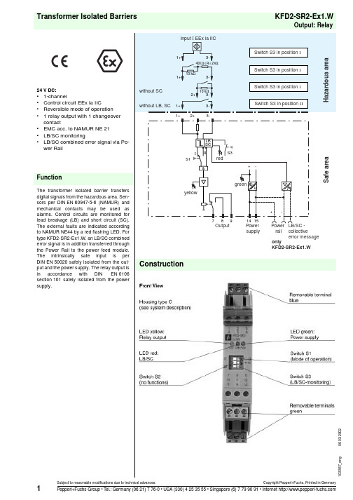
KFD2-SR2-Ex1.W06.03.2002Transformer Isolated BarriersOutput: RelayTechnical dataKFD2-SR2-Ex1.W103367_e n g06.03.2002Power supply Connection typePower Rail or terminals 14+, 15-Rated operational voltage 20 ... 30 V DC Rated operational current 20 ... 23 mA Safety maximum voltage U m 40 V DC Ripple£ 10 %Input (intrinsically safe)Connection type terminals 1+, 2+, 3-Nominal datain accordance with IEC 60947-5-6 (NAMUR, DIN 19234); see system description for electrical dataQuiescent voltage/Short-circuit current approx. 8 V DC / approx. 8 mA Switching point/Switching hysteresis 1.2 ... 2.1 mA / approx. 0.2 mA Input pulse length/Input pulse interval Š 20 ms / Š 20 msLead monitoringbreakage J £ 0.1 mA , short-circuit J > 6 mADetails of certificate of conformity Certification numberPTB 00 ATEX 2080 ; for additional certifications refer to the approval list Group, category, ignition protection method¬ II (1) G D [EEx ia] IIC Voltage U 010.5 V Current I 013 mA PowerP 034 mWAllowable circuit valuesIgnition protection class, category [EEx ia and EEx ib]Explosion groupIIA IIB IIC External capacitance 75 µF 16.8 µF 2.41 µF External inductance1000 mH 840 mH 210 mH Entity parameter Certification number J.I.3002773FM control drawingNo. 116-0035Suitable for installation in division 2 yesConnection type terminals 1, 3; 2, 3; 4, 6; 5, 6Input IVoltage V OC12.9 V Current I SC19.8 mAExplosion groupA&B C&E D, F&G Max. external capacitance C a 1.273 µF 3.82 µF 10.18 µF Max. external inductance L a84.8 mH 254.4 mH 678.4 mH Safety parameter UL control drawing E 106378CSA control drawing LR 36087-13Control drawing No. 116-0047Connection type terminals 1, 3; 2, 3; 4, 6; 5, 6Input ISafety parameter 12.6 V / 650 Ohm Voltage V OC12.9 V Current I SC19.8 mAExplosion groupA&B C&E D, F&G Max. external capacitance C a 1.273 µF 3.82 µF 10.18 µF Max. external inductance L a84.88 mH 298.7 mH 744.4 mHOutput (not intrinsically safe)Connection type terminals 7, 8, 9Outputsignal ; relayContact loading253 V AC / 2 A / cos j > 0.7; 40 V DC / 2 A ohmic load; from january 2002 increase of the con-tact rating to 4A for 115 V AC switching voltage. The respective connection data are shown on the type plate.Mechanical life107 switchingsEnergized/De-energized delay approx. 20 ms / approx. 20 ms Transfer characteristics Switching frequency < 10 HzGalvanic isolation Input/Outputsafe galvanic isolation acc. to EN 50020, voltage peak value 375 V Input/Power supplysafe galvanic isolation acc. to EN 50020, voltage peak value 375 V103367_e n g 06.03.2002Output/Power supply safe isolation acc. to DIN VDE 0106, design isolation voltage 253 V eff Ambient conditions Ambient temperature -20 ... 60 °C (253 ... 333 K)Standard conformity Inputin accordance with IEC 60947-5-6 (NAMUR, DIN 19234); see system description for electrical dataCoordination of insulation accord. to DIN EN 50178Galvanic isolation accord. to DIN EN 50178Climatic conditionsaccord. to DIN IEC 721Electromagnetic compatibility accord. to EN 50081-2 / EN 50082-2, NAMUR NE 21Mechanical specifications Massapprox. 150 gPower Rail PR 05Power Rail UPR 05Power feed module KFD2-EB2The devices are supplied with 24 V DC due to the power feed module KFD2-EB2 and via the Power Rail PR 05 or UPR 05, simultaneously the combined fault indication will be evaluated.Each power feed module serves the fusing and monitoring of groups with up to 100 single devices. The PR 05 Power Rail is an inset component for the DIN rail. The UPR 05 Power Rail is a complete unit consisting of the electrical insert and an aluminum 35 x 15 x 2000 mm DIN rail.Devices are simply snapped onto it for an electrical connection.Without the use of a Power Rail, the power supply to the device is directly through the device terminals.Accessories:103367_e n g 06.03.2002。
- 1、下载文档前请自行甄别文档内容的完整性,平台不提供额外的编辑、内容补充、找答案等附加服务。
- 2、"仅部分预览"的文档,不可在线预览部分如存在完整性等问题,可反馈申请退款(可完整预览的文档不适用该条件!)。
- 3、如文档侵犯您的权益,请联系客服反馈,我们会尽快为您处理(人工客服工作时间:9:00-18:30)。
倍加福安全栅KFD2-STC5-Ex2模拟量输入安全栅介绍
倍加福安全栅KFD2-STC5-Ex2模拟量输入安全栅介绍
KFD2-STC5-Ex2
智能发射机电源
2通道隔离屏障,24 V直流电源(电源导轨),输入2线和3线SMART发射机和2线SMART电流源,输出4 mA...20ma电流吸收/电流源,带有测试点的端子,最高SIL 2 (sc3) acc。
符合IEC/EN 61508,外壳宽度:20mm,通道数量:2通道,HART通信,测试插座,安全完整性等级(SIL): SIL 2,额定电压:18 (30v)
DC,现场设备:2线制变送器,现场设备[2]:3线制变送器
KFD2-STC5-Ex2
通用规范
信号型模拟输入
功能安全相关参数
安全完整性等级(SIL) SIL 2
系统能力(SC
供应
连接电源轨或端子14+,15-
额定电压18…30v直流
波动在供应容忍范围内
最大负载时功耗≤1.4 W
最大负载时功耗≤2.6 W
输入
连接侧现场侧
连接端子1+、2-、3;4+ 5- 6
输入信号4…20马
开路电压/短路电流端子1+、3;4+, 6: 23 V / 25 mA
最大输入电阻。
265 Ω端子2-、3;5- 6,最多。
330 Ω端子1+、3;4 + 6 20ma时可用电压≥16v;≥20v, 4ma,端子1+,3;4 + 6
输出
连接侧控制侧
连接端子7+、8-、9-;10+, 11-, 12-(下沉)
端子7-、8+、9+;10-, 11+, 12+(来源)
参见其他信息
加载0…600Ω
输出信号4…20ma(过载>25马)
涟漪马克斯。
50µA rms
外部电源(回路)2…30v直流
如果外部电压为>19 V,要求负载≥((V - 19) / 0.02) Ω。
V表示外部电压的值。
终端9和12的内部250 Ω电阻可用作负载。
传输特性
在20°C(68°F),4…20马
≤10µA,包括校准、线性、迟滞、负载和电源电压波动
环境温度影响≤0.25µA/K
频率范围将场侧转入控制侧:频带宽度为1vpp信号为0…7.5 kHz (-3 dB)
安全区域到危险区域:带宽1 VSS信号0.3…7.5 kHz (-3 dB)
沉降时间200µs
上升/下降时间100µs
电隔离
输出/电源功能绝缘,额定绝缘电压50v AC
输出/输出功能绝缘,额定绝缘电压50v AC
指标/设置
显示元件
贴标空间用于贴标在前面
指令一致
电磁兼容性
指令2014/30/ eu en 61326-1:2013(工业场所)
整合
电磁兼容性ne 21:2012
EN 61326 - 3 - 2:20 08
防护等级iec 60529:2001
ul 61010-1:2012
环境条件
环境温度-20…60°c(-4…140°F)
将环境温度范围扩展到70°C(158°F),请参阅手册了解必要的安装条件
防护等级ip20
连接螺钉端子
质量约。
200克
尺寸20 × 124 × 115毫米(0.8 × 4.9 × 4.5英寸)(宽×高×深),外壳类型B2
安装在35mm DIN安装导轨上。
EN 60715:2001
与危险区域有关的应用数据
最大安全电压250v(注意!额定电压可低一些。
)
设备端子1+、3-;4 + 6 -
电压26.2 V
电压27.25 V
电流93 mA
功率634兆瓦
设备端子2-、3+;5 - 6 +
电压30v
电流115ma
最大功率1w
电压2v
电流8.5 mA
功率4.3 mW
设备端子1+、2/3-;4 +, - 5/6
电压26.2 V
电压27.25 V
功率784兆瓦
证书cml 17atex 3030X
标记Ex- hexagon II 3G Ex- IIC T4 Gc
电隔离
输入/输出安全电气隔离acc。
符合IEC/EN 60079-11:2007,电压峰值375 V 输入/电源安全电气隔离acc。
符合IEC/EN 60079-11:2007,电压峰值375 V
倍加福安全栅KFD2-STC5-Ex2模拟量输入安全栅介绍。