a low profile antenna array
StealthRay Spec Sheet
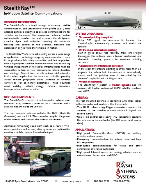
StealthRay™In-Motion Satellite CommunicationsPRODUCT DESCRIPTION:The StealthRay™ is a breakthrough in two-way satellite communication. The StealthRay’s™ low profile (5.9”), array antenna system is designed to provide communications for vehicles on-the-move. The innovative antenna system automatically searches for and acquires the designated satellite signal and maintains pointing via automatic tracking and control of the azimuth, elevation and polarization angles while the vehicle is in motion.The StealthRay™ offers valuable utility across a wide range of applications, including emergency communications, since it can provide public safety authorities and first responders with a high-speed satellite communications link to moving vehicles independent of terrestrial infrastructures that are susceptible to local service interruptions, natural disasters and sabotage. Since it does not rely on terrestrial networks, it also offers applications for industries typically operating across remote geographic areas unserved by wireless carriers as well as military operations. Those industries most notably include energy, natural resources, transportation and conservation.SYSTEM COMPONENTS:The StealthRay™ consists of a low-profile, vehicle roof-mounted array antenna connected to a controller and a satellite modem inside the vehicle.The roof mounted antenna includes the BUC (Block Up Converter) and the LNB. The controller supplies the power to the antenna and controls the antenna movements.Additional networking equipment such as a router, Wi-Fi access point, as well as encryption systems are optional for creating a mobile, secure, in-motion hotspot.45.3” L35.4” W5.9” HSYSTEM OPERATION:No manual pointing is requiredUsing GPS signals to determine its location, the StealthRay™ automatically acquires and tracks the satellite.On-the-move automatic re-peakingBuilt-in gyros allow fast recovery from line-of-sight blockages. The antenna uses a hybrid mechanical and electronic scanning process to maintain pointing accuracy.Adjacent satellite interference protectionIn the event the antenna pointing is off by more than 0.5 degrees, the return link transmission is automatically muted until the pointing error is corrected by the antenna’s sophisticated tracking system. Modem compatibilityThe StealthRay™ system is modem agnostic and will support all RaySat authorized SCPC satellite modems and VSATs.CABLING:The roof mounted antenna is connected with three cables to the controller and modem within the vehicle:Two RJ-58 cables using F-type connectors connect the antenna to the satellite modem (transmit signal and receive signal).One RJ-58 control cable using TNC connectors connects the antenna to the controller (for DC power and control data).APPLICATIONS:High-speed Com-on-the-Move (COTM) for military vehicles and operationsEmergency communications for federal, state and local first respondersHigh-speed communications for trains and other commercial enterprise customersHigh-speed Internet access for moving vehicles such as motor-homes, buses, vans and SUV’s8460-D Tyco Road, Vienna, VA 22182 800.561.9280 703-584-3770StealthRay™ SpecificationsKEY FEATURESAntenna• Low profile 5.9" height - blends into the vehicle and can include matching color options • Simple installation on any luggage rack, flat roof or under the roof with a false ceiling; only the radome is visible• Stand alone unit, complete with all required RF hardware including Block Up Converter (BUC)• Operates off a vehicle's standard 12V DC power supply with minimal power consumption • Auto satellite tracking / in-motion operation / hands free operation • Compatible with any Ku-band satellite and is modem agnosticANTENNA PERFORMANCE AND DATA RATES *Receive (forward link) Up to 15MbpsTransmit (return link) 64 Kbps - 384 Kbps (internal 3 watt BUC)512 Kbps - 2Mbps (external BUC)* System performance varies as a function of the satellite link (beam EIRP and G/T) and the satellite modem parameters.ANTENNA PHYSICAL CHARACTERISTICSDimensions 45.3” x 35.4” x 5.9” Rack with complete systemWeight 66 lbs total (antenna - 62lbs, controller - 4lbs) Electrical interfacesPower supply 30V DC provided by the antenna controller Output\Input impendence 50 ohmsEnvironmentalAmbient temperature range Operational: -13o F to 122oF ambient Relative Humidity 0-100% condensingMobile Platform Ground Speed Operational up to 220 mphANTENNA CHARACTERISTICSFrequency range Receive 11.7 - 12.75 GHzTransmit14.0 - 14.5 GHzPolarization Orthogonal linear (auto polarization control) Uplink EIRP 32 dBW Gain TX: 27 dBi RX: 29.3 dBi G/T 7.6 dB/°K @ 30° Sidelobe level -12 dB TX Cross polarization > 30 dB Azimuth / elevation beam coverage 360° continuous Az 25° - 70° El IF input / outputL-Band 950 - 2150 MHzSIGNAL ACQUISITION AND TRACKINGSignal acquisition & lock Automatic <60˚ sec Polarization angle adjustment Automatic Tracking speed 60°/sec Re-acquisition < 1 sec for blockage length up to 3 min Azimuth tracking accuracy < 0.3° nominal Elevation tracking accuracy < 0.35° Polarization adjustment accuracy < 1°ANTENNA CONTROL UNIT (ACU)Power supply 12V DC Power consumption 5A (ACU & antenna w/ internal BUC) System interface CLI over RS-232 Modem interface Proprietary over RS-232RaySat Antenna Systems, LLC • 8460-D Tyco Rd. • Vienna, VA 22182 • 703.584.3770 • ©2006, RaySat Antenna Systems, LLC. All rights reserved.。
可折叠平面反射阵列天线的研究

摘要摘要平面反射阵列天线综合了传统抛物面天线和微带阵列天线的特点,它将反射面制作成平面型,没有复杂的馈电结构、剖面低、加工简单、成本低。
选择柔性板材作为介质材料的可折叠平面反射阵列天线不仅继承了平面反射阵列天线的常规优点,且具有质量轻、收拢体积小、成本低、可实现折叠与展开等进一步优势,具有广泛的应用前景。
本论文围绕X波段可折叠平面反射阵列天线的实现问题进行了详细的理论和实验研究,具体内容如下:1.为了实现平面反射阵列天线的可折叠特性,选择一种柔性板材作为介质材料是本论文至关重要的一步。
通过广泛调研并结合实际情况,最终把聚酰亚胺薄膜材料作为研究天线的介质材料,它具有厚度薄、韧度好、耐磨等特点,可实现折叠与展开,符合本论文的设计要求。
2.为了拓宽天线带宽以及降低加工难度,提出了一种结构简单、具有多谐振特点的宽带特性单元。
在充分考察结构参数、入射角、频率对天线单元相移曲线影响的基础上,优化获得了宽带范围内的线性相移曲线,给出了天线单元结构的设计方案。
3.利用上述给出的单元结构,设计了一种小口径(180mm180mm⨯)的可折叠平面反射阵天线,仿真表明:平面反射阵天线与同等口径的抛物面具有一致的远场方向图,在频率9.5GHz11.5GHz~(相对带宽20%)范围内,增益最大跌落小于1dB。
初步验证了单元的准确性,为制作大口径天线奠定了基础。
4.设计了大口径(300mm324mm⨯)的可折叠平面反射阵列天线,并完成了加工与测试。
测试结果表明:在频率9.5GHz11.5GHz~(相对带宽20%)范围内,最高副瓣电平均小于16dB-,其最高实测增益为28.78dB,最低实测增益为28.2dB,最大实测增益跌落在1dB范围内,实现了宽带宽特性。
在中心频率为10GHz处,实测增益为28.37dB,副瓣电平为20dB-,3dB波束宽度为6.1度,此时天线口径效率为50.6%,实现了高辐射效率。
介质材料本身可卷曲、轻质量且厚度很薄,仅为0.05mm,实现了可折叠、轻量化、收拢体积小等特性。
机载小型圆极化天线设计

机载小型圆极化天线设计张悦【期刊名称】《《无线电工程》》【年(卷),期】2019(049)011【总页数】5页(P995-999)【关键词】圆极化; 小型化; 耦合弧; 低剖面; 全向【作者】张悦【作者单位】中国人民解放军91550部队辽宁大连 116023【正文语种】中文【中图分类】TN820 引言全向圆极化天线在全球定位系统和个人移动系统之类的无线通信系统中越来越受欢迎,同时也逐渐应用到了机载系统中[1]。
传统机载天线大多为线极化[2-8],如果机载天线可以同时接收垂直极化和水平极化,那么就减轻了机载天线和地面端天线之间的极化失配,改善了信号质量。
而大多圆极化天线都是定向辐射[9-10],无法满足机载全向通信的需求。
为了满足技术需求,过去几年提出了许多设计全向圆极化天线的方法。
在文献[11]中,天线通过贴片和槽的辐射来产生圆极化全向辐射;文献[12]中提出了一种装有改进的圆形贴片介质谐振器天线,它可以实现双频和双圆极化全向辐射;文献[13]中,通过基于圆柱结构的缝隙阵列天线实现全向圆极化工作。
上述天线均可以产生全向圆极化辐射,但它们的体积和重量都较大。
为了使全向圆极化天线的结构小型化,科研工作者开展了一些研究。
Shi和Liu[14]提出了一种带有缝隙和短路引脚的圆形贴片天线,剖面高度为0.028λ0;文献[15]中天线利用圆形贴片的两个单极模式工作,其剖面高度减小到0.024λ0。
虽然这些天线的轮廓可以进一步减小,但它们的横向尺寸仍比较大,分别为0.78λ0和1.44λ0。
文献[16]中采用了4个弯曲偶极子,实现了尺寸为0.35λ0×0.35λ0×0.13λ0的小型化全向圆极化天线;到目前为止,文献[17]中实现了最小的全向圆极化天线,其尺寸为0.22λ0×0.22λ0×0.076λ0。
众所周知,天线的电尺寸与其性能直接相关[18-22]。
因此,与上述天线相比,本文提出了一种具有更小尺寸的新型全向圆极化天线。
天线原理
Transmitting antenna
Power Amplifier
Modulator
Sound-toelectronic signal Transducer
• Receiving system
Receiving antenna
Preamplifier
Filter
Radiated free-space wave
4
• Transmission-line Thevenin equivalent
-
Impedance matching between free space and a guiding device. Antenna impedance.
5
• Directional property of antennas
• Invented by Prof. Yagi and Instructor Uda in 1926. • The importance of Yagi-Uda antenna was not recognized in Japan until its use in radar systems by British and America was discovered in 1942 when Japanese army occupied Singapore.
Human vision
A radar system
9
Antenna Classifications
• According to operational function: transmitting and receiving • According to frequency band: VLF, HF, VHF, UHF, S-band, Xband, K-band, W-band etc. • According to structural property: wire antennas (dipole, loop etc.) and aperture antennas (slot, horn, reflector, patch) • According to assembly: single element or group of elements (array)
- 1、下载文档前请自行甄别文档内容的完整性,平台不提供额外的编辑、内容补充、找答案等附加服务。
- 2、"仅部分预览"的文档,不可在线预览部分如存在完整性等问题,可反馈申请退款(可完整预览的文档不适用该条件!)。
- 3、如文档侵犯您的权益,请联系客服反馈,我们会尽快为您处理(人工客服工作时间:9:00-18:30)。
A Low Profile Antenna Array for Underground Mine Communication
Rong-Yu Chao and Kah-Seng Chung School of Electrical and Electronic Engineering
Curtin University of Technology
GPO Box U1987, Perth 6001
Western Australia
Abstract The special environment in underground mines which features severe multipath fading and high attenuation rate in UHF band re-
quires the antenna to have low profile, sim- ple structure, polarisation diversity, directiv- ity and high gain. A unique small antenna array consisting of low profile wire elements is designed for this particular application. Opti- misation of various array parameters such as interelement spacing and element length with respect to array gain and frequency bandwidth is undertaken by using Moment Method. Ef- fect to the array performance of a rectangular
conducting box is also investigated. Measurement in a building corridor has ver- ified the effectiveness of this antenna array for underground communication.
1 INTRODUCTION Good communication system in underground mines can largely increase safety and production output. Unfortunately, it has been a neglected area in the mining industry mainly due to the difficulties of im- plementing such system and the high cost involved. Expensive leaky cables or low-capacity conducting
wires are often used to provide a mobile communica, tion environment in underground mines[l][Z]. How- ever, for increased safety and instantaneous com-
munication to each person, extensive coverage and constant remote-controlled monitoring on wme haz- ardous areas are necessary. These demands favour the application of UHF radio systems[3]. Because of the special environment in underground mines which features severe multipath fading and high attenuation rate in UHF band[2][4], it is impor- tant for antennas to have low profile, simplestructure, polarisation diversity, unidirectional pattern and high gain. This paper presents the design of an antenna array using low profile inverted-F wire element. 2 UHF PROPAGATION FEATURES IN TUNNELS AND THE PRO- POSED ARRAY In UHF band, hard rock and coal bounding an un- derground mine tunnel act as relatively low loss di- electrics with dielectric constants in the range 5-10. Radio wave transmission takes the form of waveg- uide propagation, because the wavelength is much smaller than the tunnel dimensions. Wave attenu- ation through a tunnel is mainly caused by propaga- tion loss into the surrounding materials, ohmic loss is negligible at such a high frequency. The attenu- ation of the wave (in dB) increases nearly linearly with increasing distance which is a characteristic of wave guide propagation. Due to the geometrical di- mension of most underground mine tunnels, where the height is smaller than width, horizontal polarisa- tion produces significantly lower transmission loss at a given distance than does vertical polarisation in a line-of-sight path. However complete signal depolari- sation will happen around corners. Cross polarisation produces a loss intermediate between horizontal and vertical[4][5][6]. Because of the above mentioned features of UHF propagation in tunnels, an antenna with simple struc- ture, horizontal or cross polarisation and high gain will be an ideal one. If a monopole is used, it has to mounted on the side walls of the tunnel to provide a horizontally polarised field. This would not be a good location from concerns of personnel safety and the antenna vulnerability to damage. Hence ceiling- mount is preferred. Another important supporting
705 SINGAPORE ICCW94 0-7803-2046-8/94/$4.00 '1 994
IEEE
Authorized licensed use limited to: CHINA UNIVERSITY OF MINING AND TECHNOLOGY. Downloaded on December 2, 2009 at 22:43 from IEEE Xplore. Restrictions apply. Gh D2 Y Figure 1: Three-element inverted-F array factor for this mounting pwition is that the ceiling
in most mine tunnels is reinforced with metals which provide a good ground for antennas.
The inverted-F antenna (IFA) chosen here has a low profile compared with a quarter wavelength monopole antenna, and yet has a similar directiv- ity gain[I. In additional to its radiation pattern of vertical electrical field which is equivalent to that of a monopole, it also has a horizontally polarised r%
diation pattern due to its horizontal element. Be cause of this polarisation diversity, it has been found to have a better performance than a quarter wave- length monopole in environment where strong multi- path fading effect exists[8]. As shown in Fig.1, three such antennas are used to form an array to achieve high gain and unidirection- ality. The array is driven through the central element while the elements at each side of the central element act as a director and reflector, respectively. Since the two vertical wires of each IFA are both connected to the ground except the central IFA, there is virtually no effect if we remove one vertical wire. Feed point to the central IFA is different from the conventional IFA in order to achieve resonance and impedance match- ing. 3 ARRAY PARAMETERS OPTIMI- SATION Array parameters such as interelement spacing, ele- ment length and height are critical for good perfor- mance. In optimising these parameters with respect 12 I 2 4 6 6' 0 D1 (cm) D1 (cm) Figure 2: Array gains and bandwidth vs D1 to directivity gain and bandwidth, moment method is used to include the interelement coupling effect which strongly affects the current distribution on the array elements because they are relatively small compared to the wavelength. Simulation has also been done when this array is mounted on a rectangular metal box. Wire grid and small patch models are used to enable us to calculate the current distribution on the array and the box using moment method[9]. When the array is mounted on an infinitely large ground plane, the simulation results of gain and band- width with respect to the distance D1 between #1 and #2 elements are shown in Fig.2. As the distance increases from l.Ocm to B.Ocm, the horizontal gain Gh is always decreasing, while the vertical gain G,