ISCOM系列交换机简明配置手册(v1.0)
ISCOM2126EA-MA(REV.B)用户使用手册201009

ISCOM2126EA-MA(REV.B)用户使用手册2011年2月瑞斯康达科技发展股份有限公司为客户提供全方位的技术支持和服务。
直接向瑞斯康达科技发展股份有限公司购买产品的用户,可与瑞斯康达科技发展股份有限公司各地办事处或用户服务中心联系,也可直接与公司总部联系。
读者如有任何关于产品的问题,或者有意进一步了解公司相关产品,可采用下列方式与我们联系:公司网址:技术支持热线:400-890-1001 8610-82883110(7×24小时)技术支持传真:8610-82885200,010-********技术支持邮箱:help@客户投诉热线:8610-82884499-3600公司总部地址:北京海淀区上地六街28号院2号楼邮政编码:100085—————————————————————————————————————————————声明Copyright ©2010瑞斯康达科技发展股份有限公司版权所有,保留一切权利。
非经本公司书面许可,任何单位和个人不得擅自摘抄、复制本书内容的部分或全部,并不得以任何形式传播。
是瑞斯康达科技发展股份有限公司的注册商标。
对于本手册中出现的其它商标,由各自的所有人拥有。
这里的产品和服务名称都为瑞斯康达科技发展股份有限公司的商标。
由于产品版本升级或其它原因,本手册内容会不定期进行更新。
除非另有约定,本手册仅作为使用指导,本手册中的所有陈述、信息和建议不构成任何明示或暗示的担保。
前言版本说明:该手册适用于ISCOM2126EA-MA交换机VER B.00硬件版本读者对象:设备安装、维护人员相关手册:《ISCOM2126EA-MA系列交换机命令手册》《ISCOM2126EA-MA系列交换机配置指导手册》文章结构:第一章前言主要概述手册中涉及内容以及相关参考文挡,并对相关术语进行解释说明第二章规格尺寸对设备规格尺寸以及工作环境进行说明第三章设备外观对设备面板及指示灯进行说明第四章安装及使用方法对设备安装工程中所使用的线缆及可能用到的子卡进行说明第五章注意事项对于在安装过程中设备之外的细节要求进行说明。
JetNet 5020G 工业 16 FE 加 4 GbE SFP 以太网交换机快速安装指南 V1.
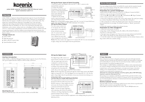
JetNet 5020G Industrial 16 FE plus 4 GbE/SFP Ethernet SwitchQuick Installation Guide V1.0JetNet 5020G is a high port density Ethernet Switch supports 16 ports Fast Ethernet, and 4 ports Gigabit Ethernet in RJ-45 or SFP for fiber connection. It is designed for field site data convergence to backbone network and up to control data center. The highly heavy industrial Electric-Magnetic Compatibility level, wide operating temperature and voltage provides excellent environmental tolerance to bear the applications which are installed in out -door or the environment with high noise interference, such as factory, railway track-site or Intelligent Traffic Control System (I.T.C.S. ). It also adopts comprehensive network control protocols to enhance network transport performance. with those brilliant system design and network features, the JetNet 5020G will be the best network transmission device for your industrial Ethernet Switch solution.Package Check ListJetNet 5020G DIN Mounting kitDB-9 to RJ-45 Console Cable Quick Installation GuideWiring the Power Inputs & Earth Grounding1. Insert the positive and negative wires into the V+ and V- contact on the terminal block connector.2. Connect the ChassisGrounding to Earth Ground system to obtain electromagnetic immunity to resist lighting, electro static discharge and electric fast transient.3. Tighten the wire-clamp screws to prevent the power wires from being loosened.Notes: The recommended working voltage is DC 24V. Use the UL Listed LPS Power supply with output Rating 10~60V VDC, minimum 2.5A currents.Wiring the Relay OutputThe relay output contacts are in the bottom side. The relay output (DO) is controlled by the pre-defined operating rules. To activate relay output function, please refer to the User’s Manual for more relay output management information.Notes: The relay contact only supports 0.5 A current, DC 24V. It is not recommended to apply voltage and current higher than the specifications.Wiring the Digital InputThe Digital Input (DI) contacts are in the bottom. It accepts one external DC type signal input and can be configured to send alert message through Ethernet when the signal is changed. The signal may trigger and generated by external powerswitch, like as door open trigger switch for control cabinet.Note: the DI accepts DC type signal and supports isolated input circuit with Digital High Level input DC 11V~30V and Digital Low Level input DC 0V~10V. Do not apply voltage higher than the specification; it may cause internal circuit damage or a wrong action of DI.Connecting the Surge/Lighting protectionThe surge protection activate screw located on the bottom side that nearby the power and DI/DO connector. Always tighten the screw and ensure the Chassis-Grounding screw is connected with Earth-Ground well.Note: 1. Ensure the Surge/Lighting is well connecting with Chassis Grounding. 2. Remove the Surge/Lighting Screw before perform insulation/Hi-pot testing.3. Never install or work on/with the equipment or the cabling during the period of its lightning activity.You can configure JetNet 5020G via the RS-232 console with the attached console cable. Or you can remotely manage the switch via network. You can choose Telnet/SSH, Web/HTTPS management.Preparation for console managementAttach the RS-232 DB9 connector to your PC’s COM port. Connect the RJ-45 connector to the console port of the JetNet Switch.1. Go to Start ► Program ► Accessories ► Communication ► Hyper Terminal2. Give a name to the new console connection.3. Choose the COM name and select the correct serial settings. The serial port settings are as below: Baud Rate:115200/Parity: None/Data Bit: 8/Stop Bit: 14. After connected, you will see the Switch login request. Type the username and password and then you can login. The default username is “admin”, password is “admin”.5. Follow the manual to configure the software features.Preparation for Web management1. Launch the web browser on the PC.2. Type http://JetNet Managed Switch_IP_Address (The default IP address is 192.168.10.1.), then press Enter.3. The login screen will appear next. Type in the user name and password and click “OK” button. The default user name and password is admin/admin.4. At the left column of the web management interface are the software features, where ring column will list the available settings.5 Years WarrantyEach of Korenix’s product is designed, produced, and tested with high industrial standard. Korenix warrants that the product(s) shall be free from defects in materials and workmanship for a period of five (5) years from the date of delivery provided that the product was properly installed and used.This warranty is voided if defects, malfunctions or failures of the warranted product are caused by damage resulting from force measure (such as floods, fire, etc.), other external forces such as power disturbances, over spec power input, or incorrect cabling; or the warranted product is misused, abused, or operated, altered and repaired in an unauthorized or improper way.Attention! To avoid system damage caused by sparks, please DO NOT plug in power connector when power is on.The product is in compliance with Directive 2002/95/EC and 2011/65/EU of the European Parliament and of the Council of 27 January 2003 on the restriction of the use of certain hazardous substances in electrical and electronics equipment (RoHS Directives & RoHS 2.0)Korenix Customer ServiceKorenixCARE is Korenix Technology’s global service center, where our professional staffs are ready to answer your questions at any time.EmailaddressofKorenixGlobalServiceCenter:********************SupportInterface IntroductionJetNet 5020G is a DIN Rail Managed Ethernet Switch supports 16 ports Fast Ethernet, and 4 ports Gigabit Ethernet in RJ-45 or SFP for fiber connection.Mounting the unitMount the DIN Rail clip on the rear of JetNet 5020G on the DIN Rail.JetNet 5020G 工业级16百兆, 4千兆管理型以太网络交换机快速安装指南V1.0JetNet 5020G 是一款高密度端口的以太网交换机,支持16端口快速以太网和4个千兆以太网支持RJ-45或SFP 的电口与光口共模设计。
DCN交换机简明配置手册v2.1

3950-X系列交换机从1.6.X(1.3.X)升级到6.0.X.X一、组网需求DCS-3950-X系列交换机本地使用BootRom模式和远程使用Telnet方式将设备版本从1.6.X(1.3.X)升级到6.0.x.x或更高版本。
二、适用范围本文档描述DCN 3950-X交换机版本升级步骤及注意事项。
适用于以下型号的交换机IMG版本从1.6.X(1.3.X)升级到6.0.x.x或更高版本。
DCS-3950-26CDCS-3950-28CDCS-3950-52CDCS-3950-28CTDCS-3950-52CTDCS-3950-28CT-POE对应升级过程和使用到的版本请参照文档中的描述。
本文档只适用于3950-X系列交换机从1.6.X(1.3.X)升级到6.0.X.X。
如果升级到6.0.x.x之后希望恢复到1.6.X,则设备配置无法恢复。
由于BootRom模式下从1.6.x(1.3.x)升级到6.0.X.X版本需要重启交换机4次。
而在命令行模式下升级1.6.x(1.3.x)到6.0.x.x只需要重启2次。
建议升级时在命令行模式下进行升级操作。
三、BootRom模式,1.6.X(1.3.X)升级到6.0.X.X3.1组网图3.2配置步骤3.2.1 升级PC机使用Console线连接到交换机。
配置升级服务器地址为192.168.1.1/24,升级服务器使用FTP Server方式,FTP用户名为“dcn”密码为“123456”。
并将升级所需的文件放置在FTP根目录。
3.2.2 配置BootRom下的升级参数,在BootRom模式下,将1.6.x (1.3.x)的nos.img文件升级到 1.6.131.0.nos.img交换机内存自检时,按Ctrl+B进入BootRom模式:Testing RAM...268,435,456 RAM配置BootRom下的升级参数:[Boot]: setconfigHost IP Address: [10.1.1.1] 192.168.1.2Server IP Address: [10.1.1.2] 192.168.1.1FTP(1) or TFTP(2): [2] 1FTP User Name: [guest] dcnFTP User Password: [switch] 123456Network interface configure OK.BootRom模式下,升级nos.img文件到 1.6.131.1:[Boot]: load dcs-3950-x-1.6.1.131.1.nos.imgLoading...entry = 0x10010size = 0x26e40cLoading file ok![Boot]: write imgFile exists, overwrite? (Y/N)?[N] yWriting nos.img..Write file OK.3.2.3 3950-X nos.img升级到 1.6.131.1 后,重启设备,在“#”提示符下输入“convert startup-config”命令转换配置。
华为S5516交换机-配置指导V.1.01-05_POS接口配置
注意 POS 接口不能同时允许对内自环和对外回波
请在 POS 接口配置模式下进行配置
表PC-1-5 设置 POS 接口对内自环和对外回波 操作 允许 POS 接口对内自环/对 外回波 禁止 POS 接口对内自环和 对外回波 命令 loopback { internal | line } no loopback
口间的配置一定要相同
1-2
Quidway S8016 路由交换机 用户手册 配置指导分册 POS 接口配置
第 1 章 POS 接口配置
j1 为通道跟踪字节 长度为 15 字节 口之间连接在通道层次上的连续性 省值为 Huawei S8016
和 j0 的作用相似 用于检测两个端 两个端口间的配置一定要相同 j1 的缺
第 2 章 PPP 协议配置 ............................................................................................................... 2-1
2.1 PPP 协议简介..................................................................................................................... 2-1 2.2 PPP 协议配置..................................................................................................................... 2-2 2.2.1 配置 PPP 验证方式及用户名 用户口令 ................................................................ 2-2 2.2.2 配置 PPP 协商参数 ................................................................................................. 2-4 2.2.3 配置 keepalive 参数 ................................................................................................ 2-4 2.3 PPP 协议监控和维护 .......................................................................................................... 2-5 2.4 PPP 协议配置示例 ............................................................................................................. 2-5 2.4.1 PAP 验证举例 .......................................................................................................... 2-5 2.4.2 CHAP 验证举例 ....................................................................................................... 2-6
中兴 ZXR10 8900E 系列交换机数据手册说明书

ZTE ZXR10 8900E Series Switch Data Sheet Updated: Sep 27, 2017Product OverviewThe ZXR10 8900E Series switch is high-end modular switch featuring big switching capacity, L2/L3/MPLS service capability, high-performance, superior reliability and enhanced security. The ZXR10 8900E Series switch is designed for core and aggregation layer of next-generation campus network scenario. The ZXR10 8900E Series switch allows fast, non-blocking switching and has full IPv6 feature. In addition, The ZXR10 8900E Series switch offers a variety of technologies to fulfill better reliability, easy maintenance and low power consumption: VSC2.0(Virtual Switch Cluster), BFD (Bi-directional Forwarding Detection), Zero-touch provisioning, IEEE 802.3az Energy Efficient Ethernet (EEE) etc, which help customer to build future-oriented low TCO(Total Cost of Ownership) networks.The ZXR10 8900E Series switch uses advanced hardware architecture and modular design, up to 10.24Tbps wire-speed switching capacity with high capacity service cards including: 48 x10GE interfaces, 8 x 40GE interfaces, and 4 x100GE interfaces.Coupled with distributed ROSng Software Platform, the ZXR10 8900E Series switch delivers the following products:● 8902E: 2 interface board slots, 2 control board slots and 2 power supply module slots. 4RU, side-to-side airflow.● 8905E: 5 interface board slots, 2 control switching slots and 3 power module slots. 10RU, side-to-side airflow.● 8908E: 8 interface board slots, 2 control switching slots and 3 power module slots. 13RU, side-to-side airflow.8902E 8905E 8908E 8912E 8908E‐H 8912E‐H● 8912E: 12 interface board slots, 2 control switching slots and 3 power module slots. 17RU, side-to-side airflow.● 8908E-H: 8 interface board slots, 2 control board slots, 4 independent switching fabric board slots and 3 power module slots. 17RU, side-to-side airflow.● 8912E-H: 12 interface board slots, 2 control board slots, 4 independent switching fabric board slots and 3 power module slots. 21RU, side-to-side airflow.Product Features• Up to 10.24Tbps Wire-speed Switching Capacity, 4 x 100GE/ 48 x 10GEInterface Card-The ZXR10 8900E Series switch supports up to 10.24Tbps wire-speed switching capacity with up to 1.28Tbps switching capacity per slot. It can deliver customer a sustainable high-performance campus core and aggregation network and carrier aggregation network for next 5 years. -The ZXR10 8900E Series switch line cards covers diverse Ethernet interfaces including: FE/GE/10GE/ 40GE/100GE.The high capacity line cards such as 48 ports wire-speed 10GE, 8 ports wire-speed 40GE and 4 ports wire-speed 100GE can bring customers with infinite bandwidth capability. Meanwhile, in the scenario that only need a few 10GE and GE interfaces, the 10GE and GE interface mixed line card can be deployed in order to help customer increase the line card usage and save investment.• Innovative VSC2.0 (Virtual Switch Cluster) Technology-VSC2.0 Capability: Stacking bandwidth between the VSC switches can be up to 320Gbps, which can solve the bandwidth bottleneck of VSC and deliver customer a real-time non-blocking VSC system. By using optical Ethernet interface for stacking, the stacking distance can be up to 80km and even more, it helps customer to get rid of distance restriction while designing a reliable VSC system. -Reliability: Independent out-band management makes the control plane and forwarding plane separated. Through real-time control information hot-standby technology, the VSC system can achieve seamless switchover when failure happens.- Saving investments: No need special stacking line card, the normal line card can be used for VSC connecting. When some interfaces are used for VSC, the other interfaces on this line card can also be used for traffic forwarding. No interfaces are wasted and that helps customer to save investments.- Flexibility: Master and slave in VSC2.0 works in 1+N redundancy mode, MAD(Multi-active Detect) technology is used to detect and avoid dual master in VSC system when failure happens. Together with real-time hot-standby and seamless switchover it brings customer a more flexible VSC network.• Powerful Service Bearing Capability-By supporting rich L2 switching and L3 routing functions and low latency forwarding, The ZXR10 8900E Series switch can bear lots of service including WLAN, Internet, Voice, Video, Enterprise private network and other data services. -Support distributed L2/L3 MPLS VPN; support VPLS, H-VPLS and VPWS. The ZXR10 8900E Series switch can also support MCE. By supporting these features, it delivers customer VPN service capability. -Support comprehensive L2/L3 Multicast protocols; support PIM-SM, PIM-DM, PIM-SSM, MLD and IGMP Snooping, fulfill the requirements for IPTV, multi-terminal high-definition video surveillance and video conferencing services. -Support POE/POE+ interface card, which delivers customer more flexible service access choice.• Comprehensive IPv6 Solution-The ZXR10 8900E Series switch has passed IPv6 Ready Phase 2 Gold Medal Certification issued by IPv6 Forum. -Support rich IPv6 unicast routing protocols: IPv6 static routing, RIPng, OSPFv3, IS-ISv6, and BGP4+ and multicast features: MLD v1/v2, MLD snooping, PIMv6, etc. -Support rich IPv4-to-IPv6 tunnel technologies: IPv6 manual tunnels, 6-to-4 tunnel, ISATAP tunnel and IPv4-compatible automatic tunnel, etc.• Enhanced Reliability, Multi-Dimensional Security-Control plane and forwarding plane are physically separated on the ZXR10 8900E-H Series switch. -All the key components of the ZXR10 8900E Series switch are redundant design and hot pluggable, including: main control boards, switching boards, power supply modules, fan modules. -Support GR (Graceful Restart) to realize non-stop forwarding for OSFP/BGP/IS-IS to reduce the affection brought by network failures. -Support Ethernet OAM, including IEEE 802.3ah, 802.1ag, Y .1731, and help to monitor network real-time operating status and fulfill fast fault detection, fault location. -Support various authentication methods such as 802.1x, Radius, TACACS+. Support CPU overload protection, anti-DDOS, deliver customer a security network. -The ZXR10 8900E supports MAC security (MACSec) that enables hop-by-hop secure data transmission. Therefore, the ZXR10 8900E can be applied to scenarios that need high requirements on data confidentiality, such as government and finance sectors.• Easy Maintenance, Saving OPEX-Support independent monitoring plane, which can monitor the working temperature, fan situation, power situation, etc. It can help customer hold the network running status in real time. -Support Zero-touch provisioning, the software and the configuration files can be loaded automatically, Reduce provision process and man power requirement. -Support the SQA (Service Quality Analyzer), detecting the network quality periodically or in real time. In order to provide better quality of service for more valuable services.• Green for More-Support IEEE 802.3az EEE (Energy Efficient Ethernet), via chip-grade power management, interfaces and line card can automatically sleep when no traffic.- Side-to-side shoot-through airflow increases the heat dissipation efficiency. Save up to12% overall power consumption.- The fan rotational speed can be automatically and manually adjusted by 5 levels in accordance with the temperatures inside the switch. It not only saves the power consumption, but also reduces the noise and extends the life cycle of fans.- Complying with ROHS, WEEE and ISO14001 certification, No plumbum (Pb) in not only product materials but also the whole processing technic. Meanwhile, use re-cycles degradable packing materials, practice green for more.System SpecificationParameters 8902E 8905E 8908E 8912E 8908E-H 8912E-H Height 4RU 10RU 13RU 17RU 17RU 20RU Dimensions (H*W*D, mm) 175*442* 420 442*442* 446 575*442* 446 753*442* 446 753*442* 446 889*442* 446 Switching Capacity 960Gbps4.8Tbps7.68Tbps7.68Tbps10.24Tbps10.24TbpsPacket ForwardingRate 720Mpps 3,600Mpps 5,760Mpps 5,760Mpps 7,680Mpps 7,680MppsNumber of Line Card Slots 2 5 8 12 8 12Number of Main ControlSlots 2 2 2 2 2 2Number of Switching Card Slots N/A N/A N/A N/A 4(3+1) 4(3+1)Interface Type FE/GE RJ45; GE SFP; 10GE SFP+; 40GE CFP; 40GE QSFP+; 100GE CFP2 Weight <24kg<51.8kg<65.5kg<90.6kg<77.4kg<98.9kgAC Power Supply Rated input voltage range: 100V~240V,50Hz~60Hz Max input voltage range: 90V~286V, 47Hz~63HzDC Power SupplyRated input voltage: -48V/-60V Input voltage range: -72V ~ -40VParameters 8902E 8905E 8908E 8912E 8908E-H 8912E-HHVDC Power Supply 240V/336VPower Consumption <576W <1,589W <2,278W <3,217W <2,624W <3,565W Max POE Consumption 1300W 4250W5100W5100W5100W5100WPower Redundancy Pattern AC/ DC: 1+1AC/DC :2+1/1+1Heat Dissipation Pattern Fan cooling,independent fan subracks, Side-to-Side AirflowHeat Dissipation <1,611 BTU/h <4,445 BTU/h <6,373 BTU/h <9,000 BTU/h <8,471 BTU/h <9,425 BTU/hWorking Temperature Long term working temperature: -5o C ~ +45o C; Short term working temperature: -10o C ~ +55o C;Storage temperature -40o C ~ +70o C Working Humidity 5%~95% (non-condensing)Working Altitude <3,000 metersMTBF/MTTR>200,000 hours/ <30 minutesService SpecificationFunctionThe ZXR10 8900E Series SwitchL2 Features Support IEEE 802.1p (COS), IEEE 802.1q (VLAN), IEEE 802.3x Support IEEE 802.1d (STP)/ 802.1w (RSTP)/ 802.1s (MSTP) Support IEEE 802.1ad (QinQ), Selective QinQSupport IEEE 802.3ad (LACP), MC-LAG (Multi-Chassis Link Aggregation Group)Support IEEE 802.3z (1000BASE-X) / 802.3ab (1000BaseT) Support IEEE 802.3ae (10Gbase), Support IEEE 802.3ba (40Gbase) Support IEEE 802.3ba (100Gbase)Support IEEE 802.3af (PoE), IEEE 802.3at (PoE+)Support Port mirroring, Traffic mirroring Support VLAN switching, VLAN translation Support PVLAN, SuperVLAN Support GVRP Support LLDPL3 FeaturesSupport IPv4 routing protocols, such as Static routing, Policy based routing , RIP, OSPF, BGP, and IS-ISSupport DHCP server/ relay/proxy, DHCP snoopingSupport IPv6 dynamic routing protocols, such as Static routing, Policy based routing , RIPng, OSPFv3, ISISv6, and BGP4+ Support ND, DHCPv6, PMTUSupport manual IPv6 tunnel, 6to4 tunnel, 6PE, ISATAP tunnel MulticastSupport IGMP v1/v2/v3, IGMPv1/v2/v3 snoopingSupport PIM-SM, PIM-DM, PIM-SSM, MSDP, MBGP, Any-RPSupport administratively scoped multicast/ IPTV, MVR, Support MLD V1/V2、MLD V1/V2 Snooping Support PIMv6MPLSSupport basic MPLS functions, LDPSupport MCESupport VPLS,VPWS, H-VPLS Support MPLS L2 VPN, MPLS L3 VPNQOSSupport traffic classification based on Layer 2 headers, Layer 3 protocols, Layer 4 protocols, and 802.1p prioritySupport queue scheduling algorithms, such as SP, WRR, DWRR, SP+WRR Support congestion avoidance mechanisms, such as WRED and tail drop Support policing/shaping based on port/flow SecuritySupport L2-L4 ACLSupport Ingress/ Egress ACLSupport 802.1x authentication and 802.1x serverSupport MAC authenticationSupport AAA/ RADIUS and TACACS+ authentication for login users Support SSH v1.0/v2.0 serverSupport CPU anti-attack, CPU overload protection, Support STP Root Guard, BPDU guard,Support URPFSupport RIP/OSPF/BGP MD5 encryption checking Support MACsecEquipment managementSupport CLI, Telnet, SSH, Local and remote (Radius/Tacacs+) authentication of user Support SNMP v1/v2/v3Support RMON Support NTP Support Syslog, Sflow Support openflow1.3ReliabilitySupport VSC2.0(Virtual Switch Cluster)Support 1+1/2+1 Redundant Control module/Power supply/Fan module Support 3+1 redundancy switching boards (Only 8900E-H) Support Hot plugging Support LACP , MC-LAGSupport ZESR/ZESR+ (ZTE Ethernet Switch Ring) Support ERPS V2Support VRRP,VRRPv3,VRRPE Support NSF/GR for OSFP/BGP/IS-IS Support BFD for VRRP/ BGP/ IS-IS/ OSPF Support Ethernet OAM (802.1ag and 802.3ah) Support ITU-Y.1731Application ScenarioAggregation in Campus NetworkThe ZXR10 8900E Series switch can be used in the next-generation campus network aggregation scenarios as the core/aggregation layer devices. The ZXR10 8900E Series switch supports powerful service capability such as L2/L3/MPLS, IPv6, POE, which provides 100GE, 40GE, high-density 10GE interfaces and fulfills the bearing requirements of WLAN, Voice, Video, Surveillance etc. It can be used to build the high-reliability, extendable, secure, manageable data switching network to provide the comprehensive product solution.Order InformationChassisRS-8902E-CHS 8902E assembly chassis 8905E-CHS2-AC 8905E AC assembly chassis 8905E-CHS2-DC 8905E DC assembly chassis 8908E-CHS2-AC 8908E AC assembly chassis 8908E-CHS2-DC 8908E DC assembly chassis 8912E-CHS2-AC8912E AC assembly chassis8912E-CHS2-DC8912E DC assembly chassis 8908E-H-CHS-AC8908E-H AC assembly chassis 8908E-H-CHS-DC8908E-H DC assembly chassis 8912E-H-CHS-AC8912E-H AC assembly chassis 8912E-H-CHS-DC 8912E-H DC assembly chassisControl Switching Board 8902EMCS1A8902E 1A type control switching board 8902EMCS1D8902E 1D type control switching board 8905EMCS1A8905E 1A type control switching board 8905EMCS1D8905E 1D type control switching board 8905EMCS3A8905E 3A type control switching board 8905EMCS3E8905E 3E type control switching board 8908EMCS1A8908E 1A type control switching board 8908EMCS1D8908E 1D type control switching board 8908EMCS3A8908E 3A type control switching board 8908EMCS3E8908E 3E type control switching board 8912EMCS1A8912E 1A type control switching board 8912EMCS1D8912E 1D type control switching board 8912EMCS3A8912E 3A type control switching board 8912EMCS3E 8902E 3E type control switching boardMain Control Board8900EHMCUA 8900E-H main control board Switching Fabric Board8900EHSFU3A8900E-H Type A switching fabric board 8900EHSFU3E 8900E-H Type B switching fabric board Power Supply Module8902E-ACPWA8902E AC power supply module 8902E-DCPWA8902E DC power supply module 8900E-ACPWA8905E/8908E/8912E/8908E-H/8912E-H AC power supply module 8900E-DCPWA 8905E/8908E/8912E/8908E-H/8912E-H DC power supply module Fan Supply Module8902E-FAN8902E fan subracks 8905E-FAN8905E fan subracks 8908E-FAN8908E fan subracks 8912E-FAN8912E fan subracks 8908E-H-FAN8908E-H fan subracks 8912E-H-FAN 8912E-H fan subracks100M/1000M Ethernet electrical interface cardsS1GT24A24-port 10/100/1000 BASE-T interface card (S1, RJ45) S1GT48A 48-port 10/100/1000 BASE-T interface card (S1, RJ45) S1GP48A48-port 10/100/1000 BASE-T interface card (S1, RJ45, POE/POE+) H1GT48A48-port 10/100/1000 BASE-T interface card (H1, RJ45) H2GT48D 48-port 10/100/1000 BASE-T interface card (H2, RJ45)100M/1000M Ethernet optical interface cardsS1GF24A24-port 100/1000 BASE-X interface card (S1, SFP) S1GF48A 48-port 100/1000 BASE-X interface card (S1, SFP)H1GF24A24-port 100/1000 BASE-X interface card (H1, SFP) H1GF48A48-port 100/1000 BASE-X interface card (H1, SFP) H2GF24D24-port 100/1000 BASE-X interface card (H2, SFP) H2GF48D 48-port 100/1000 BASE-X interface card (H2, SFP)10GE Ethernet optical interface cards S1XF12A12-port 10G BASE-X interface card (S1, SFP+) S2XF48A48-port 10G BASE-X interface card (S2, SFP+) H1XF4A4-port 10G BASE-X interface card (H1, SFP+) H1XF8A8-port 10G BASE-X interface card (H1, SFP+) H1XF16A16-port 10G BASE-X interface card (H1, SFP+) H1XF32A32-port 10G BASE-X interface card (H1, SFP+) H2XF8D8-port 10G BASE-X interface card (H2, SFP+) H2XF48C48-port 10G BASE-X interface card (H2, SFP+) H3XF12D 12-port 10G BASE-X interface card (H3, SFP+) 10 GE and GE optical/electrical interface cardsH1GF28C12X2C2-port 10GE BASE-X and 28-port GE BASE-X (12-port Combo) interface card (H1,SFP+/SFP/RJ45) H1GF28C12X4C4-port 10GE BASE-X and 28-port GE BASE-X (12-port Combo) interface card (H1,SFP+/SFP/RJ45) H1GT28C12X2B2-port 10GE BASE-X and 28-port GE BASE-T (12-port Combo) interface card (H1,SFP+/SFP/RJ45) H1GT28C12X4B 4-port 10GE BASE-X and 28-port GE BASE-T (12-port Combo) interfacecard (H1,SFP+/SFP/RJ45)40GE Ethernet optical interface cardsS2LQ6L2A 8-port 40GE BASE-X interface card (S2, 2 port CFP, 6 port QSFP+) 100GE Ethernet optical interface cardsH2UC2C2-port 100GE BASE-X interface card (H2, 2 port CFP2) H2UC4C 4-port 100GE BASE-X interface card (H2, 2 port CFP2) 10GE WAN optical interface cardsH1XW4B 4-port 10G BASE-X interface card (H1, SFP+) Software R8900E-SW-BASIC8900E Basic System Software R8900E-SWUD8900E Basic System Software Upgrade SWLIC-MPLS 8900E MPLS Software ServiceNO. 55, Hi-tech Road South,ShenZhen,P. R. China Postcode: 518057Web: Tel: +86-755-26770000Fax: +86-755-26771999。
项目一 路由器IOS的基本配置v1.0

[项目一]路由器IOS的基本配置[项目内容]通过构建一个简单网络,学习路由器的连接方法,启动、登陆路由器,熟悉IOS工作界面,掌握IOS中的各级模式,掌握路由器的配置;学习如何把配置文件和IOS备份到TFTP服务器上,如何从TFTP服务器将配置文件和IOS恢复到路由器;学习口令恢复操作和其它常用命令的使用。
[操作步骤]一.绘制网络拓扑图绘制如图1.1所示的网络拓扑。
图1.1 网络拓扑注意,PC0使用RS232接口与Router0的Console(控制台)端口连接。
图1.2 设备属性对话框单击Server0,出现设备属性对话框,单击Config选项卡,如图1.2所示,将Display Name 修改为TFTP。
用同样的方法将PC1的Display Name 修改为Console。
修改后的拓扑如图1.3所示。
图1.3 修改属性后的网络拓扑二.启动路由器1.配置超级终端单击图1.3中的PC终端Console,出现属性对话框,单击Desktop选项卡,如图1.4所示,选择超级终端通信程序Terminal,出现配置对话框如图1.5所示。
按图1.5所示配置好Terminal属性,单击OK按钮,就可以使用超级终端对路由器进行配置了。
图1.4 PC终端属性对话框图1.5 超级终端通信程序Term inal属性设置对话框图1.6 路由器启动信息2.启动路由器超级终端和路由器连接好之后,超级终端中就可以看到路由器的启动过程,显示路由器的软件、硬件信息。
如图1.6所示,路由器开机后会进入到一种称为setup模式的特殊配置模式,提示信息是:--- System Configuration Dialog ---Continue with configuration dialog? [yes/no]:按Ctrl+C键或回答“no”并按Enter键,此时中断setup模式,并提示:Press RETURN to get started!图1.7 用户界面——Command Line Interface (CLI)按Enter键,就进入了用户模式,显示用户界面——Command Line Interface (CLI),这是Cisco IOS 传统的基于命令行的控制台环境,如图1.7所示。
瑞斯康达ISCOM5800E(REV.A)用户使用手册

—————————————————————————————————————————
声明
Copyright ©2011 瑞斯康达科技发展股份有限公司 版权所有,保留一切权利。 非经本公司书面许可,任何单位和个人不得擅自摘抄、复制本书内容的部分或全部,并不得以任注册商标。 对于本手册中出现的其它商标,由各自的所有人拥有。 这里的产品和服务名称都为瑞斯康达科技发展股份有限公司的商标。 由于产品版本升级或其它原因,本手册内容会不定期进行更新。除非另有约定,本手册仅作为使 用指导,本手册中的所有陈述、信息和建议不构成任何明示或暗示的担保。
第 2 章 设备结构 -------------------------------------------------------------------------------------------------- 17 2.1 总体结构 ----------------------------------------------------------------------------------------------------- 17 2.2 背面结构说明----------------------------------------------------------------------------------------------- 18 2.3 部件说明 ----------------------------------------------------------------------------------------------------- 19 2.3.1 电源盘 -------------------------------------------------------------------------------------------------19 2.3.2 风扇盒 -------------------------------------------------------------------------------------------------20 2.3.3 槽位分布 ----------------------------------------------------------------------------------------------21 2.4 物理参数 ----------------------------------------------------------------------------------------------------- 22 2.5 供电条件 ----------------------------------------------------------------------------------------------------- 22 2.6 工作条件 ----------------------------------------------------------------------------------------------------- 22 2.7 贮存条件 ----------------------------------------------------------------------------------------------------- 22
Aruba WLAN简明配置手册-v1

Aruba WLAN 简明配置手册目录目录 (2)1.初始化配置 (3)1.1.无线控制器初始化配置 (3)1.2.恢复出厂设置-无线控制器 (4)1.3.恢复出厂设置-Aruba AP (4)2.基本网络参数配置及维护 (6)2.1.基本网络参数配置 (6)2.2.控制器基本维护操作 (7)2.3.管理员帐号管理 (9)3.理解Aruba WLAN配置结构框架 (11)3.1.基本WLAN服务配置 (11)3.2.基于角色的用户策略管理 (12)4.配置范例 (14)4.1.建立WPA2-PSK服务 (14)4.2.建立Portal认证 (19)4.3.建立802.1X认证 (28)4.4.同一SSID中为不同用户配置不同的权限 (38)4.5.设置用户期限 (39)4.6.设定区域管理 (43)4.7.配置日志服务器 (49)4.8.带宽限制 (49)1.初始化配置1.1.无线控制器初始化配置Enter System name [Aruba3400]:Enter VLAN 1 interface IP address [172.16.0.254]:Enter VLAN 1 interface subnet mask [255.255.255.0]:Enter IP Default gateway [none]:Enter Switch Role, (master|local) [master]: ————————————控制器角色Enter Country code (ISO-3166), <ctrl-I> for supported list: cn———————控制器所在国家代码,此选项影响You have chosen Country code CN for China (yes|no)?:yes可用RF channel及功率参数Enter Time Zone [PST-8:0]: UTC8:0——————————————-时区系统(UTC、PST等)及所在时区Enter Time in UTC [06:07:59]: 6:11:30——————————————所选时区系统的标准时间而不是本地时间,Enter Date (MM/DD/YYYY) [8/14/2011]: 否则控制器的时钟可能就不对了。
- 1、下载文档前请自行甄别文档内容的完整性,平台不提供额外的编辑、内容补充、找答案等附加服务。
- 2、"仅部分预览"的文档,不可在线预览部分如存在完整性等问题,可反馈申请退款(可完整预览的文档不适用该条件!)。
- 3、如文档侵犯您的权益,请联系客服反馈,我们会尽快为您处理(人工客服工作时间:9:00-18:30)。
ISCOM系列交换机简明配置手册(v1.0)一、接入交换机ISCOM2000系列 ........................................................................... (2)1. VLAN的划分 ........................................................................... ....................... 2 2. 保护端口的设置 ........................................................................... .. (2)3. 管理IP的配置............................................................................ .................. 34. 环路检测功能的开启 ........................................................................... .......... 3 5. 端口限速功能 ........................................................................... .................... 3 二、汇聚交换机ISCOM2800系列............................................................................ . (3)1. VLAN的划分 ........................................................................... ....................... 3 2. 保护端口的设置 ........................................................................... ................. 3 3. 管理IP的配置............................................................................ .................. 3 4. 环路检测功能或生成树功能的开启 ................................................................ 3 5. 端口限速功能 ........................................................................... .................... 4 6. ACL访问控制功能。
.......................................................................... ............ 4 7. 风暴抑制功能的开启 ........................................................................... .......... 4 8. 配置双TAG功能 ........................................................................... ................. 4 三、功能配置步骤说明............................................................................ (4)1、登陆 ........................................................................... . (4)2、用户模式 ........................................................................... ........................... 4 3、常用操作命令 ........................................................................... .................... 5 4、添加用户的配置 ........................................................................... ................. 5 5、交换机远程管理地址的配置 ..........................................................................5 6、交换机的网关配置 ........................................................................... ............. 5 7、端口的配置 ........................................................................... ........................ 6 8、创建VLAN ......................................................................... ............................ 6 9、保护端口模式 ........................................................................... .................... 7 10、风暴抑制............................................................................ ......................... 7 11、端口环路............................................................................ ......................... 7 12、端口镜像............................................................................ ......................... 8 13、防病毒配置:.......................................................................... .................... 8 14. 配置防ARP攻击 ........................................................................... ............... 9 15、防用户私接DHCP服务器: ........................................................................10 16 配置trap:(用于告警信息上传) ................................................................ 10 17、远程访问控制............................................................................ ................ 10 18、Q-in-Q的配置(网络结构如图所示).........................................................11 四、配置示例: ......................................................................... (11)1.ISCOM2826E ................................................................... . (11)2.ISCOM2026.................................................................. (15)1城域网边缘 ISCOM2826E ISCOM2026 ISCOM2026 ISCOM2026PPPOE拨号上网上图为ISCOM系列交换机的典型使用方式。
ISCOM2000系列或者是ISCOM2100系列的交换机做最终用户的接入设备,ISCOM2800系列做汇聚。
下面介绍通常情况下,用做接入设备的ISCOM2000交换机及ISCOM2800交换机的一些典型配置及需要注意的地方:一、接入交换机ISCOM2000系列对于直接接终端用户的设备来说,通常有以下几项功能需要配置: 1. VLAN的划分这里需要划分业务VLAN,用户VLAN,同时要考虑上连端口是否要透传VLAN。
2. 保护端口的设置如果要保证同一VLAN内的用户相互之间不可访问,需要开启保护端口的功能。
23. 管理IP的配置这里要注意管理IP匹配的VLAN,如果用户需要从交换机的下端进行管理,要注意将IP匹配到相应的VLAN上。
4. 环路检测功能的开启为避免环路的产生,需要开启环路检测的功能,因生成树协议收敛速度慢,建议直接接终端用户的设备上,开启环路检测功能而关闭生成树协议。
这里要注意两点:一个是环路检测功能开启时,必须关闭生成树协议,这两个协议之间有冲突,不可以同时开启。
第二是环路检测功能只在用户端口开启,上连端口不要开启环路检测功能。
5. 端口限速功能这里要注意:因端口的入方向的限速与端口的流控功能相关,所以开启端口入方向的限速时,必须把端口的流控功能开启。