2海道测量(第二章海道测量基础)资料
航海学第二章--海图解读
2. 局部比例尺与基准比例尺 二、地图投影分类 1. 按投影变形性质分类 2. 按构成地图图网的方法分类
第一篇 基础知识
地图投影
第二章 海图
概念:按照一定的数学法则,把地球表面的一部分 或全部描述到平面上去的方法,称为地图投影。
意义:因为地面上任意一点都可以用地理坐标来确定,
所以地图投影主要就是将地面上的经纬线按一定的数学 法则绘画到平面上去,建立地图的经纬线图网。 无论将地球视为圆球体或椭圆体,其表面都是不可展的 曲面,不能无裂隙、无皱褶地将它平展开来。 不可展曲面━━> 如果按同一比例缩小:地球仪 │ └>按不同比例拉伸或压缩 :平面图 (避免裂隙和皱褶) 但不可避免产生投影变形(长度、角度、面积变形)
第一篇 基础知识
局部比例尺与基准比例尺
海图比例尺大小的意义:
第二章 海图
① 决定海图的制图精度:海图比例尺越小,海图的精度越差。 ② 决定海图作业的最高精度:比例尺越小,海图作业精度越差,
其在数值上等于海图极限精度的2倍。在海图作业中,用削 尖的铅笔尖在图上画一小点,其直径最小也有0.2mm,这是 海图作业时能够分辨和量出的最小距离。例如:在比例尺为 1:300 000的海图上,0.2mm代表地表面的距离是0.2mm X 3 000 000 = 600m,它说明在该图上进行海图作业的极限精度 为600m,即在该海图上不可能量出小于600m的长度来。 ③ 决定图上所绘制资料的详细程度:比例尺越大,图上所绘制 的资料越详细、准确,海图的可靠性程度就越高。
航海学
—海图
第一篇 基础知识
第二章 海图
海图(chart)是地图的一种,是以海洋及其 毗邻的陆地为描述对象,为满足航海的需要而专 门绘制的一种地图。海图上详细地绘画出了航海 所需要的各种资料,如岸形、岛屿、浅滩、沉船 、水深、底质、碍航物、和助航设施等。
海洋测量学

海洋测量学001海洋测量marine survey002海洋大地测量marine geodetic survey003海底控制网submarine control network004岛陆联测island-mainland connection survey005海洋水准测量marine leveling006当地平均海面local mean sea level007日平均海面daily mean sea level008月平均海面monthly mean sea level009年平均海面yearly mean sea level010多年平均海面multi-year mean sea level011平均海面季节改正seasonal correction of mean sea level012海面地形sea surface topography013海洋测量定位marine survey positioning014光学[仪器]定位optical instrument positioning015卫星定位satellite positioning016无线电定位radio positioning017水声定位acoustic positioning018组合定位integrated positioning019圆一圆定位(又称“距离一距离定位”)range-range positioning 020双曲线定位(又称“测距差定位”)hyperbolic positioning021极坐标定位(又称“距离方位定位”)polar coordinate positioning 022差分法定位differentiation positioning023位置线line of position, LOP024位置线方程equation of LOP025位置[线交]角intersection angle of LOP026位置面surface of position,SOP027定位点间距positioning space028等角定位格网equiangular positioning grid029辐射线格网radial positioning grid030双曲线格网hyperbolic positioning grid031等距圆弧格网equilong circle arc grid032等精度[曲线]图equiaccuracy chart033岸台(又称“固定台”)base station034船台(又称“移动台”)mobile station035跟踪台track station036监测台(又称“检查台”)monitor station,check station 037台链station chain038主台main station039副台slave station040相位周(又称“巷”)phase cycle,lane041相位周值(又称“巷宽”)phase cycle value,lane width 042相位稳定性phase stability043相位多值性phase ambiguity044相位漂移phase drift045固定相移fixed phase drift046联测比对comparison survey047联测比对点point of comparison survey048接收中心receiving center (注:船台接收岸台发射的无线电信号的实接收点,该点有时与天线位置不一致。
第9课时第2章2.2海图制图
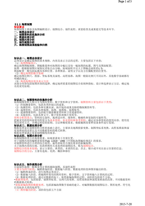
§2.2 海图制图知识要点海图制图主要涉及海图编辑设计、制图综合、制作流程、质量检查及成果提交等技术环节。
一、海图总体设计二、制图资料的收集和分析三、数据处理分析四、制图内容分析五、制作流程分析六、海图制图成果检验和归档知识点一、海图总体设计总体设计是确定海图的基本规格、内容及表示方法的过程,主要包括以下内容:(1)海图图幅设计:确定海图图幅规格、图幅数量和对海图的分幅以及每一幅海图的标题、图号及图面配置;海图一般根据制图区域情况采取自由分幅,陆域面积不宜大于图幅总面积的1/3;图面配置一般包括标题内容和位置、各种图表、说明文字以及方位圈配置的位置等。
(2)确定海图的数学基础确定海图比例尺、投影、坐标系统及深度、高程基准,海图一般除比例尺不同以外,其他数学基础都有明确的规定。
(3)构思海图内容及表示方法该部分内容包括海图内容的选择、确定地理要素的制图综合原则和指标、设计和选择表示方法、确定地名的采用原则。
知识点二、制图资料的收集和分析海图制图资料大致可分为图形资料、数字资料和文字资料。
制图资料主要包括以下类型:(1)控制测量资料,包括各类控制点的成果。
(2)海测资料,包括各种实测水深、海岸地形成果及障碍物探测资料等。
(3)成图资料,包括各种地图、海图、地图集、海图集等。
(4)遥感图像资料,包括航空摄影测量资料和卫星遥感资料。
(5)其他资料,包括各种文字、数字资料和图片资料等。
资料分析的重点:资料的完备性、地理适应性、现势性、精确性和复制的可能性等。
把被采用的资料按使用程度分为基本资料、补充资料和参考资料,确定对各种资料的使用内容、使用范围及使用方式,并确定转绘的原则、方法和精度要求,根据编图需要和设备条件进行复制。
知识点三、数据处理分析数据处理是在制图资料分析的基础上进行,主要涉及地图投影变换、制图坐标系变换,高程基准面和深度基准面的改算以及不同数据资料的格式转换。
数据处理要满足要素制图精度的要求。
第一篇第二章 第四节海图的分类和使用注意事项、电子海图

二、海图资料的可信赖程度 1.海图的测量时间和资料来源 2.海图出版、新版或改版日期与小改正 3.海图比例尺 4.测深的详尽程度 海图水深空白处,表示未经测量,应视为航海 危险区而避开 。 5.地貌精度与航标位置
三、使用海图注意事项 1.要尽可能选择现行版大比例尺海图,并要善 于鉴别海图的可信赖程度。 2.海图使用前,应根据航海通告和有关的无线 电航海警告及时加以改正。 3.海图水面空白处,表示未经测量,应视为航 海危险区避开。 4 使用中,应经常利用各种有效手段加以核实, 并注意掌握最新资料。
第七节 海图的分类和使用注意事项
一、海图分类 根据作用不同,海图可以人为航用海图和参考图 两大类。 按绘制图网的方法,即地图投影方法的不同,海 图又可分为墨卡托海图、高斯投影海图、大圆海 图和平面图等。 1、航用海图用于拟定航线、进行航迹推算和定位 等海图作业。航用海图按比例尺的大小,一般可 以分为 :
(5)、港湾图(harbour charts):其比例尺一般 大于1:100000。图上详细标有灯塔、灯标、 浮标、立标、雷达站、无线电导航设备、雾号 等各种助航标志。当图幅范围内有更大比例尺 的港湾图时,港内助航标志会作较多的取舍。 图上还详细标有各种航道及其疏浚深度或扫海 深度、锚地和锚位,以及码头、防波堤、船坞、 系船浮筒和系船灯桩等港口资料。港湾图一般 可供船舶进出港湾、锚地,通过狭窄水道及港 口管理等使用。
2、电子海图显示与信息系统的功能 海图显示; 海图作业; 海图改正; 定位与导航; 航海信息查询; 雷达信息处理; 航路监视; 航行记录;
3、电子海图显示与信息系统的主要优点: 海图信息的选择显示; 海图改正简单易行; 海图附加资料的提供 船舶驾驶自动化水平的提高; 本质性的提高航行安全性; 海图数据存储在光盘或磁盘上,便于保管和传递;
海道测量通用术语

海道测量通用术语2. 1海道测量hydrographic survey以保证航海安全为主要目的,为获取海底地形、地貌、底质、助航物和障碍物等资料, 对海洋(包括内陆水域)和海岸特征进行的测量。
主要包括控制测量、水深测呈:、海岸地形测量等。
2.2海事测绘maritime surveying and mapping为海事活动提供技术支持和服务的测绘工作。
包括港口航道图测绘、水上应急扫测、通航尺度核左测量、船舶公共航路和立线制扫测、通航水深监测等,以及编制发行官方航海图书资料、提供发布相关的航海保障信息服务等。
2.3控制测量control survey在一立区域内,为海道测量建立控制网所进行的测疑工作。
包括平而控制测疑和髙程控制测量等。
注:修改GB/T 14911-2008 的定义 3.8。
2.4水准测量leveling测定地面两点间垂直髙差或某地而点相对于某一等位而的高程的测量技术和方法。
注:修改GB/T 14911-2008 的定义 3. 12。
2.5地形测量topographic survey将地球表面的地物、地貌的平而位置和髙程按一左的比例和符号注记绘制成图的测量技术和方法。
2.6水深测量s ound i ng测左水而点至水底的竖直距离和点的平面位置的测量技术和方法。
水文观测hydrologic observation在海洋、湖泊、江河的某一点或断而上观测各种水文要素,并对观测资料进行分析整理的技术和方法。
2.8航标测量navigation mark survey助航标志测量对助航标志的位置、髙程、布设环境等进行的测量。
2.9航彳亍障碍物探测observation of navigation obstruction碍航物探测对有碍船舶航行安全的礁石、浅滩、沉船、沉物等障碍物的准确位置、最浅深度、延伸范囤、性质等进行探测。
2. 10底质探测bottom characteristic detection对海底表层组成的物质种类、性质和厚度等属性进行的探测与分析。
2024注册测绘师《综合能力》讲义_第2章 海洋测绘(1)

2024年注册测绘师资格考试《测绘综合能力》
讲义
海洋测绘内容,
【基本概念和测绘内容】
海洋控制测量深度基准面的联测传递。
【海控、深度基准面】
海洋定位、水深测量测深结果进行必要改正,【三维
空间数据获得】
海图的类型和投影方式海图制图综合,【海图制作】
成果进行整理、检查、验收和归档【质量检查、成果提交】
海洋测量海图编制海洋相临陆地江河湖泊
大气水文
海底
海道测量分类
CGCS2000高斯-克吕格墨卡托
1985国家高程基准
当地平均海面
理论最低潮面
2 cm
5cm
海域要素陆地要素
自由分幅基本原则
坐标系
投影墨卡托投影
高斯-克吕格投影
日晷投影
(H1) (H2)(Hc)
1:100 000
10 cm
基本原则
验潮站的水位应归算到深度基准面上长期验潮站深度基准面
短期验潮站和临时验潮站深度基准面
利用两条以上的位置线求得海上某点位置
光学定位。
第二章 测量学的基本知识
平面直角坐标系(x,y)
建 筑 施 工 坐 标 系 高 斯 平 面 直 角 坐 标 系
独 立 平 面 直 角 坐 标 系
三、高斯平面直角坐标系
1.地图投影的概念 地面观测值
归算
有利于大地测量计算、研究地 球的形状、大小,探索空间技 术。
椭球面
大地问题解算
大地经纬度
按照一定的数学法则建立起椭球
•难以用来直接控制测图;
A
N
大地高
P’
法线方向
O 赤道 B
S
(3)以起赤道面作为确定点位纬度的参考面:过地面点P的椭球面法线与赤道面的 夹角称为该点的大地纬度B,并规定由赤道面向北为北纬,向南为南纬,以0°~ 90°表示。
3.空间直角坐标与大地坐标之间的转换
X N H cos B cos L Y N H cos B sinL 2 Z N 1 e H sinB
3 9
15 75 81 87 93 99
105 111
117
123 129
135
171
177 177
1
2
3
13
14
15
16
17
18
19
20
21
22
23
29
30
31
0
6
12
18
72
78
84
90
96
102 108
114
120 126
S N
线,并与子午线的投影曲线相互垂直且凹向两极。
(3)高斯平面直角坐标系
坐标系原点: 中央子午线和赤道的交点
N
x
海道测量海图术语
8.31
海图印刷chart printing
用光化学方法或电子出版技术将海图出版原图转印到纸张或其他材料上的过程。
注:修改GB/T 14477-2008的定义10.1。
8.32
四色印刷four color printing
用减色法三原色色料(黄、品红、青)及黑色色料进行印刷的工艺方法。
8.15
航海通告 notice tomariner
刊载有关航行安全事项和航海图书改正内容的定期出版物。
[GB/T 15315-2008,定义3.1]
8.16
改正通告 notice to mariner
时效性较长、需要据其对国家海事行政主管部门出版的航海图书进行改正的通告项目,也称改正通告项。
[JT/T 702-2019,定义3.1]
对海图符号的样式、尺寸、颜色以及注记和图廓整饰规格的统一规定。
8.20
海图注记lettering of chart
海图上表示海图要素的名称、意义和数量等属性的文字及数字的通称。
8.21
海图设计chart design
通过规划、实验确定新编海图的内容、形式及其生产技术流程的工作。
8.22
制图资料cartographic data
8.17
航标表list of light
记载助航标志信息的航海书表,内容一般包括航标的名称、位置、特征、灯质、信号、作用及其他工作信息等内容。
8.18
计算机辅助制图computer-aided cartography
通过计算机软硬件辅助人判断和完成特定制图功能的系统。
8.19
海图图式symbolandabbreviationonchart
海道测量岸线地形测量术语
海道测量岸线地形测量术语5.1地形 topography地物和地貌的总称。
[GB/T 16820-2009,定义4.12]5.2地貌 relief ;geomorphy地球表面起伏形态的总称。
[GB/T 16820-2009,定义4.10]5.3地物 feature地球表面上的各种固定性物体,可分为自然地物和人工地物。
[GB/T 16820-2009,定义4.11]5.4海岸线测量 coastlining获取海岸线数据,为图载海岸线绘制提供依据。
5.5海岸地形测量 coast topographic survey确定海岸线位置和海岸性质以及对沿海陆地地形、陆地助航标志等的测量和调查。
5.6海岸 coast在海水面和陆地接触处,经波浪、潮汐、海流等作用下形成的滨海地带。
5.7海滩 beach海岸带的一部分。
海图上称“干出滩”,指海岸线与0m等深线之间的潮侵地带。
地质学中称“潮间带”,指平均高潮线与平均低潮线之间的地带。
5.8陡岸 steep coast海岸的坡度大于50°的陡峭地段。
按剖面形态分为滩陡岸和无滩陡岸,按物质组成分为土质和石质陡岸。
5.9海岸线 coast line陆地和海洋的分界线。
在海图上,有海潮的海岸线为多年平均大潮高潮面时的水陆分界线,无海潮的海岸线为平均海平面时的水陆分界线。
注:修改GB/T 15918-2010的定义2.3.10。
5.10海岸带 coast zone海洋与陆地相互作用的地带,一般包括潮上带、潮间带、潮下带。
5.11潮间带 intertidal zone平均高潮线与平均低潮线之间的潮浸地带。
5.12潮上带 supratidal zone平均高潮线以上,特大潮汛和风暴潮海水可以淹没及激浪海水可以溅到的潮上平台。
注:修改GB/T 15918-2010的定义2.3.3。
5.13潮下带 subtidal zone平均低潮线以下至波浪对海底有明显作用的浪底线以上地带。
IHO海道测量规范S-44第五版2008年原版加标注
IHO海道测量规范第五版-2008IHO STANDARDS FOR HYDROGRAPHIC SURVEYS (S-44) 5th Edition February 2008CONTENTSPage Preface............................................................................................................................... 1 Introduction............................................................................................................................... 3 Chapter 1Classification of Surveys ....................................................................................... 5 Chapter 2Positioning ............................................................................................................. 7 Chapter 3Depths .................................................................................................................... 8 Chapter 4Other Measurements ............................................................................................ 11 Chapter 5Data Attribution ................................................................................................... 12 Chapter 6Elimination of Doubtful Data .............................................................................. 14 Table 1............................................................................................................................. 15 Glossary............................................................................................................................. 17 Annex AGuidelines for Quality Control ............................................................................ 21 Annex BGuidelines for Data Processing (25)NB:Annexes A and B will be removed from this document when the information contained in them is fully included in IHO Publication M-13 (Manual on Hydrography) 等级分类定位深度其他测量质量控制指导方针数据处理指导方针PREFACEThis publication, “Standards for Hydrographic Surveys” (S-44), is one of the series of standards developed by the International Hydrographic Organization (IHO) to help improve the safety of navigation.Formal discussions on establishing standards for hydrographic surveys began at the VII th International Hydrographic Conference (IHC) in 1957. Circular Letters to Member States in 1959 and 1962 reported on the views of Member States and the VIII th IHC in 1962 established a Working Group (WG) comprising 2 members from the USA, 1 from Brazil and 1 from Finland. The WG communicated by mail and held two meetings in conjunction with the IX th IHC in 1967 and prepared the text for Special Publication N o S-44.The 1st Edition of S-44 entitled “Accuracy Standards Recommended for Hydrographic Surveys” was published in January 1968 the Foreword to which stated that “…hydrographic surveys were classed as those conducted for the purpose of compiling nautical charts generally used by ships” and “The study confined itself to determining the density and precision of measurements necessary to portray the sea bottom and other features sufficiently accurately for navigational purposes.”Over subsequent years technologies and procedures changed and the IHO established further WGs to update S-44 with the 2nd Edition published in 1982, the 3rd in 1987 and the 4th in 1998. Throughout these revisions the basic objectives of the publication have remained substantially unchanged and this remains so with this 5th Edition.The Terms of Reference for the WG established to prepare the 5th Edition of S-44 included inter alia: a desire for clearer guidance regarding sea floor features and listed a number of concerns including system capabilities for detecting features and the characteristics of features to be detected. The WG concluded that S-44 sets minimum standards for surveys conducted for the safety of surface navigation. The WG considered it to be the responsibility of each national authority to determine the precise characteristics of features to be detected relevant to their organization and to determine the ability of particular systems and their procedures to detect such features. The WG further concluded that the design and construction of targets used to demonstrate system detection capabilities is the responsibility of national authorities. The reference to cubic features> 1 or 2 metres in size used in these Standards provides a basis for understanding that features of at least this size should be detected.The principal changes made from the 4th Edition are:The division of Order 1 into 1a where a full sea floor search is required and 1b where it is not required. The removal of Order 3 as it was considered that there was no longer a need to differentiate this from Order 2.The replacement, in most cases, of the words “accuracy”and “error”by “uncertainty”. Errors exist and are the differences between the measured value and the true value. Since the true value is never known it follows that the error itself cannot be known. Uncertainty is a statistical assessment of the likely magnitude of this error. This terminology is increasingly being used in measurement: see ISO/IEC 98: 1995 “Guide to the expression of uncertainty inmeasurement” (due to be updated in 2008) and ISO/IEC 99:2007 “International Vocabulary of Metrology – Basic and general concepts and associated terms (VIM).The Glossary has been updated and some terms which the WG consider fundamental to the understanding of these Standards are repeated in the Introduction.The WG considered that information on “How to Survey” w as not appropriate to these Standards and this information has been removed from the 5th Edition. However the WG acknowledges the usefulness of this guidance and the information has been retained in two annexes. The WG recommends that this information should be transferred to IHO Publication M-13 (Manual on Hydrography) at which time the annexes should be removed from S-44.A minimum spot spacing for bathymetric LIDAR has been included in Table 1 for Order 1b surveys where full sea floor search is not required.Finally it was the view of the WG that S-44 provides “Standards for Hydrographic Surveys” and that it is the responsibility of individual Hydrographic Offices / Organizations to prepare “Specifications” based on these Standards. Specifications will be more system specific and as such will be quite dynamic as systems change.INTRODUCTIONThis publication is designed to provide a set of standards for the execution of hydrographic surveys for the collection of data which will primarily be used to compile navigational charts to be used for the safety of surface navigation and the protection of the marine environment. It must be realised that this publication only provides the minimum standards that are to be achieved. Where the bathymetry and expected shipping use requires it, hydrographic offices / organisations wishing to gather data may need to define more stringent standards. Also, this publication does not contain procedures for setting up the necessary equipment, for conducting the survey or for processing the resultant data. These procedures (which are a fundamental part of the complete survey system) must be developed by the hydrographic office/organisation wishing to gather data that is compliant with these Standards. Consideration must be made of the order of survey they wish to achieve, the equipment they have at their disposal and the type of topography that they intend to survey. Annexes A and B provide guidelines for Quality control and Data Processing and it is intended that these will be moved to the Manual on Hydrography (IHO Publication M-13) which provides further guidance on how to perform hydrographic surveys.There is nothing to stop users adopting these Standards for other uses. Indeed, such a broadening of the use of these Standards is welcomed. However, users who wish to adopt these for other means must bear in mind the reason why they were written and therefore accept that not all parts may be suitable for their specific needs.To be compliant with an S-44 Order a survey must be compliant with ALL specifications for that order included in these Standards.It is also important to note that the adequacy of a survey is the end product of the entire survey system and processes used during its collection. The uncertainties quoted in the following chapters reflect the total propagated uncertainties of all parts of the system. Simply using a piece of equipment that is theoretically capable of meeting the required uncertainty is not necessarily sufficient to meet the requirements of these Standards. How the equipment is set up, used and how it interacts with the other components in the complete survey system must all be taken into consideration.All components and their combination must be capable of providing data to the required standard. The hydrographic office / organisation needs to satisfy itself that this is so by, for example, conducting appropriate trials with the equipment to be used and by ensuring that adequate calibrations are performed prior to, as well as during and, if appropriate, after the survey being carried out. The surveyor is an essential component of the survey process and must possess sufficient knowledge and experience to be able to operate the system to the required standard. Measuring this can be difficult although surveying qualifications (e.g. having passed an IHO Cat A/B recognised hydrographic surveying course) may be of considerable benefit in making this assessment.It should be noted that the issue of this new edition to the standard does not invalidate surveys, or the charts and nautical publications based on them, conducted in accordance with previous editions, but rather sets the standards for future data collection to better respond to user needs.It should also be noted that where the sea floor is dynamic (e.g. sand waves), surveys conducted to any of the Orders in these Standards will quickly become outdated. Such areas need to be resurveyed at regular intervals to ensure that the survey data remains valid. The intervals between these resurveys, which will depend on the local conditions, should be determined by national authorities.A glossary of terms used in this publication is given after Chapter 6. Terms included in the glossary are shown in the text in italic type and in the electronic version are hyperlinked to their definition. The following “Fundamental Definitions” from the glossary are considered essential to the understanding of these Standards.FUNDAMENTAL DEFINITIONSFeature detection: The ability of a system to detect features of a defined size. These Standards specify the size of features which, for safety of navigation, should be detected during the survey.Full sea floor search: A systematic method of exploring the sea floor undertaken to detect most of the features specified in Table 1; utilising adequate detection systems, procedures and trained personnel. In practice, it is impossible to achieve 100% ensonification / 100% bathymetric coverage (the use of such terms should be discouraged).Reduced depths: Observed depths including all corrections related to the survey and post processing and reduction to the used vertical datum.Total horizontal uncertainty (THU): The component of total propagated uncertainty (TPU) calculated in the horizontal plane. Although THU is quoted as a single figure, THU is a 2 Dimensional quantity. The assumption has been made that the uncertainty is isotropic (i.e. there is negligible correlation between errors in latitude and longitude). This makes a Normal distribution circularly symmetric allowing a single number to describe the radial distribution of errors about the true value.Total propagated uncertainty (TPU):the result of uncertainty propagation,when all contributing measurement uncertainties, both random and systematic, have been included in the propagation. Uncertainty propagation combines the effects of measurement uncertainties from several sources upon the uncertainties of derived or calculated parameters.Total vertical uncertainty (TVU): The component of total propagated uncertainty(TPU) calculated in the vertical dimension. TVU is a 1 Dimensional quantity.CHAPTER 1 – CLASSIFICATION OF SURVEYSIntroductionThis chapter describes the orders of survey that are considered acceptable to allow hydrographic offices / organizations to produce navigational products that will allow the expected shipping to navigate safely across the areas surveyed. Because the requirements vary with water depth and expected shipping types, four different orders of survey are defined; each designed to cater for a range of needs.The four orders are described below along with an indication of the need that the order is expected to meet. Table 1specifies the minimum standards for each of these orders and must be read in conjunction with the detailed text in the following chapters.The agency responsible for acquiring surveys should select the order of survey that is most appropriate to the requirements of safe navigation in the area. It should be noted that a single order may not be appropriate for the entire area to be surveyed and, in these cases, the agency responsible for acquiring the survey should explicitly define where the different orders are to be used. It should also be noted that the situation discovered in the field by the surveyor may differ sufficiently enough from what was expected to warrant a change of order. For instance in an area traversed by Very Large Crude Carriers (VLCCs) and expected to be deeper than 40 metres an Order 1a survey may have been specified; however if the surveyor discovers shoals extending to less than 40 metres then it may be more appropriate to survey these shoals to Special Order.Special OrderThis is the most rigorous of the orders and its use is intended only for those areas where under-keel clearance is critical. Because under-keel clearance is critical a full sea floor search is required and the size of the features to be detected by this search is deliberately kept small. Since under-keel clearance is critical it is considered unlikely that Special Order surveys will be conducted in waters deeper than 40 metres. Examples of areas that may warrant Special Order surveys are: berthing areas, harbours and critical areas of shipping channels.Order 1aThis order is intended for those areas where the sea is sufficiently shallow to allow natural or man-made features on the seabed to be a concern to the type of surface shipping expected to transit the area but where the under-keel clearance is less critical than for Special Order above. Because man-made or natural features may exist that are of concern to surface shipping, a full sea floor search is required, however the size of the feature to be detected is larger than for Special Order. Under-keel clearance becomes less critical as depth increases so the size of the feature to be detected by the full sea floor search is increased in areas where the water depth is greater than 40 metres. Order 1a surveys may be limited to water shallower than 100 metres.Order 1bThis order is intended for areas shallower than 100 metres where a general depiction of the seabed is considered adequate for the type of surface shipping expected to transit the area. A full sea floor search is not required which means some features may be missed although the maximum permissible line spacing will limit the size of the features that are likely to remain undetected. This order of survey is only recommended where under-keel clearance is not considered to be an issue. An example would be an area where the seabed characteristics are such that the likelihood of there being a man-made or natural feature on the sea floor that will endanger the type of surface vessel expected to navigate the area is low.Order 2This is the least stringent order and is intended for those areas where the depth of water is such that a general depiction of the seabed is considered adequate. A full sea floor search is not required. It is recommended that Order 2 surveys are limited to areas deeper than 100 metres as once the water depth exceeds 100 metres the existence of man-made or natural features that are large enough to impact on surface navigation and yet still remain undetected by an Order 2 survey is considered to be unlikely.CHAPTER 2 – POSITIONING2.1 Horizontal UncertaintyThe uncertainty of a position is the uncertainty at the position of the sounding or feature within the geodetic reference frame.Positions should be referenced to a geocentric reference frame based on the International Terrestrial Reference System (ITRS) e.g. WGS84. If, exceptionally, positions are referenced to the local horizontal datum, this datum should be tied to a geocentric reference frame based on ITRF.The uncertainty of a position is affected by many different parameters; the contributions of all such parameters to the total horizontal uncertainty (THU) should be accounted for.A statistical method, combining all uncertainty sources, for determining positioning uncertainty should be adopted. The position uncertainty at the 95% confidence level should be recorded together with the survey data (see also 5.3). The capability of the survey system should be demonstrated by the THU calculation.The position of soundings, dangers, other significant submerged features, navaids (fixed and floating), features significant to navigation, the coastline and topographical features should be determined such that the horizontal uncertainty meets the requirements specified in Table1. This includes all uncertainty sources not just those associated with positioning equipment.IHO STANDARDS FOR HYDROGRAPHIC SURVEYS (S-44)5th Edition February 2008CHAPTER 3 – DEPTHS3.1IntroductionThe navigation of vessels requires accurate knowledge of the water depth in order to exploit safely the maximum cargo carrying capacity, and the maximum available water for safe navigation. Where under-keel clearances are an issue the depth uncertainties must be more tightly controlled and better understood. In a similar way, the sizes of features that the survey will have or, more importantly, may not have detected, should also be defined and understood.The measured depths and drying heights shall be referenced to a vertical datum that is compatible with the products to be made or updated from the survey e.g. chart datum. Ideally this sounding datum should also be a well defined vertical datum such as, LAT, MSL, a geocentric reference frame based on ITRS or a geodetic reference level.3.2Vertical UncertaintyVertical uncertainty is to be understood as the uncertainty of the reduced depths.In determining the vertical uncertainty the sources of individual uncertainties need to be quantified. All uncertainties should be combined statistically to obtain a total vertical uncertainty (TVU).The maximum allowable vertical uncertainty for reduced depths as set out in Table 1 specifies the uncertainties to be achieved to meet each order of survey. Uncertainty related to the 95% confidence level refers to the estimation of error from the combined contribution of random errors and residuals from the correction of systematic errors. The capability of the survey system should be demonstrated by the TVU calculation.Recognising that there are both depth independent and depth dependent errors that affect the uncertainty of the depths, the formula below is to be used to compute, at the 95% confidence level, the maximum allowable TVU. The parameters “a” and “b” for each order, as given in Table 1, together with the depth “d” have to be introduced into the formula in order to calculate the maximum allowable TVU for a specific depth:Where:a represents that portion of the uncertainty that does not vary with depthb is a coefficient which represents that portion of the uncertainty thatvaries with depthd is the depthb x d represents that portion of the uncertainty that varies with depthThe vertical uncertainty at the 95% confidence level should be recorded together with the survey data (see also 5.3).IHO STANDARDS FOR HYDROGRAPHIC SURVEYS (S-44)5th Edition February 20083.3 Reductions for Tides / Water-level ObservationsObservations sufficient to determine variations in the water level across the entire survey area must be taken for the duration of the survey for the reduction of soundings to the relevant sounding datum. These may be determined either by direct measurement of the water level (i.e. by using a gauge) and if necessary carried across the survey area by co-tidal corrections or by 3D positioning techniques linked to the required sounding datum by a suitable separation model.Tidal / water-level reductions need not be applied to depths greater than 200 metres if TVU is not significantly impacted by this approximation.3.4 Depth measurementAll anomalous features previously reported in the survey area and those detected during the survey should be examined in greater detail and, if confirmed, their position and least depth determined. If a previously reported anomalous feature is not detected refer to Chapter 6 for disproving requirements. The agency responsible for survey quality may define a depth limit beyond which a detailed sea floor investigation, and thus an examination of anomalous features, is not required.For wrecks and obstructions which may have less than 40 metres clearance above them and may be dangerous to normal surface navigation, their position and the least depth over them should be determined by the best available method while meeting the depth uncertainty standard of the appropriate order in Table 1.Side scan sonar should not be used for depth measurement but to define areas requiring more detailed and accurate investigation.3.5 Feature detectionWhen a full sea floor search is required, the equipment used to conduct the survey must be demonstrably capable of detecting features of the dimensions specified in Table 1. Additionally, the equipment must be considered as part of a system (includes survey / processing equipment, procedures and personnel) that will ensure there is a high probability that these features will be detected. It is the responsibility of the hydrographic office / organisation that is gathering the data to assess the capability of any proposed system and so satisfy themselves that it is able to detect a sufficiently high proportion of any such features. The Special Order and Order 1a feature detection requirements of 1 metre and 2 metre cubes respectively are minimum requirements. Features may exist that are smaller than the size mandated for a given order but which are a hazard to navigation. It may therefore be deemed necessary by the hydrographic office / organization to detect smaller features in order to minimise the risk of undetected hazards to surface navigation.It should be noted that even when surveying with a suitable system 100% detection of features can never be guaranteed. If there is concern that features may exist within an area that may not be detected by the Survey System being used, consideration should be given to the use of an alternative system (e.g. a mechanical sweep) to increase the confidence in the minimum safe clearance depth across the area.IHO STANDARDS FOR HYDROGRAPHIC SURVEYS (S-44)5th Edition February 20083.6 Sounding Density / Line SpacingIn planning the density of soundings, both the nature of the seabed in the area and the requirements of safe surface navigation have to be taken into account to ensure an adequate sea floor search.For Special Order and Order 1a surveys no recommended maximum line spacing is given as there is an overriding requirement for full sea floor search.Full sea floor search is not required for Orders 1b and 2 and Table 1 recommends maximum line spacing (Orders 1b and 2) and bathymetric LIDAR spot density (Order 1b). The nature of the seabed needs to be assessed as early as possible in a survey in order to decide whether the line spacing / LIDAR spot density from Table 1 should be reduced or extended.CHAPTER 4 - OTHER MEASUREMENTS4.1 IntroductionThe following observations may not always be necessary but if specified in the survey requirement should meet the following standards.4.2 Seabed SamplingThe nature of the seabed should be determined in potential anchorage areas; it may be determined by physical sampling or inferred from other sensors (e.g. single beam echo sounders, side scan sonar, sub-bottom profiler, video, etc.). Physical samples should be gathered at a spacing dependent on the seabed geology and as required to ground truth any inference technique.4.3 Chart and Land Survey Vertical Datums ConnectionIHO Technical Resolution A2.5, as set out in IHO Publication M-3, requires that the datum used for tidal predictions should be the same as that used for chart datum. In order for the bathymetric data to be fully exploited the vertical datum used for tidal observations should be connected to the general land survey datum via prominent fixed marks in the vicinity of the tide gauge/station/observatory. Ellipsoidal height determinations of the vertical reference marks used for tidal observations should be made relative to a geocentric reference frame based on ITRS, preferably WGS84, or to an appropriate geodetic reference level.4.4 Tidal PredictionsTidal data may be required for analysis for the future prediction of tidal heights and the production of Tide Tables in which case observations should cover as long a period of time as possible and preferably not less than 30 days.4.5 Tidal Stream and Current ObservationsThe speed and direction of tidal streams and currents which may exceed 0.5 knot should be observed at the entrances to harbours and channels, at any change in direction of a channel, in anchorages and adjacent to wharf areas. It is also desirable to measure coastal and offshore streams and currents when they are of sufficient strength to affect surface navigation.The tidal stream and current at each position should be measured at depths sufficient to meet the requirements of normal surface navigation in the survey area. In the case of tidal streams, simultaneous observations of tidal height and meteorological conditions should be made and the period of observation should ideally be 30 days.The speed and direction of the tidal stream and current should be measured to 0.1 knot and the nearest 10º respectively, at 95% confidence level.Where there is reason to believe that seasonal river discharge influences the tidal streams and currents, measurements should be made to cover the entire period of variability.CHAPTER 5 – DATA ATTRIBUTION5.1 IntroductionTo allow a comprehensive assessment of the quality of survey data it is necessary to record or document certain information together with the survey data. Such information is important to allow exploitation of survey data by a variety of users with different requirements, especially as requirements may not be known when the survey data is collected.5.2MetadataMetadata should be comprehensive but should comprise, as a minimum, information on: - the survey in general e.g. purpose, date, area, equipment used, name of survey platform;- the geodetic reference system used, i.e. horizontal and vertical datum including ties to a geodetic reference frame based on ITRS (e.g. WGS84) if a local datum is used;- calibration procedures and results;- sound speed correction method;- tidal datum and reduction;- uncertainties achieved and the respective confidence levels;- any special or exceptional circumstances;- rules and mechanisms employed for data thinning.Metadata should preferably be an integral part of the digital survey record and conform to the “IHO S-100 Discovery Metadata Standard”, when this is adopted. Prior to the adoption of S-100, ISO 19115 can be used as a model for the metadata. If this is not feasible similar information should be included in the documentation of a survey.Agencies responsible for the survey quality should develop and document a list of metadata used for their survey data.5.3 Point Data AttributionAll data should be attributed with its uncertainty estimate at the 95% confidence level for both position and, if relevant, depth. The computed or assumed scale factor applied to the standard deviation in order to determine the uncertainty at the 95% confidence level, and/or the assumed statistical distribution of errors should be recorded in the survey‟s metadata. (For example, assuming a Normal distribution for a 1 Dimensional quantity, such as depth, the scale factor is 1.96 for 95% confidence. A statement such as “Uncertainties have been computed at 95% confidence assuming a standard deviation scale factor of 1.96 (1D) or 2.45 (2D), corresponding to the assumption of a Normal distribution of errors,” would be adequate in the metadata.) For soundings this should preferably be done for each individual sounding; however a single uncertainty estimate may be recorded for a number of soundings or even for an area, provided the difference between the individual uncertainty estimates and the collectively assigned uncertainty estimate is negligible. The attribution should, as a minimum, be sufficient to demonstrate that the requirements of these Standards have been met.。
- 1、下载文档前请自行甄别文档内容的完整性,平台不提供额外的编辑、内容补充、找答案等附加服务。
- 2、"仅部分预览"的文档,不可在线预览部分如存在完整性等问题,可反馈申请退款(可完整预览的文档不适用该条件!)。
- 3、如文档侵犯您的权益,请联系客服反馈,我们会尽快为您处理(人工客服工作时间:9:00-18:30)。
11 f(x) R
误差分布密集 (a) 误差分布函数 精度高
准确度低
B x
平均值 f(x) 准确值 平均值 误差分布离散 (b) R
精度低
准确度高
B x
图2—1 精度与准确度
第二章 海道测量基础 海道测量在技术方面正在发生根本性的转变。随着卫星定位系统的应用,特别是差分技术的使用,平面定位的精度有了较大的提高。同常规的断面测量相比,多波束和机载激光系统几乎可以提供海底的全覆盖测量。本章在分析了海道测量误差的基础上,讨论了测深密度、平面基准和垂直基准、海道测量分类等基本概念,最后对海道测量规范中海道测量误差标准进行了研究和比较。
2.1 测量误差分析 2.1.1 测量误差指标 测量误差包括偶然误差、系统误差和粗差,测量误差的大小决定了测量成果的质量。衡量测量误差的指标通常采用精度(Precision)和准确度(Accuracy)。 精度表示观测值与其数学期望(平均值)的离散程度,是指内部符合精度或可重复精度。精度表示观测值偶然误差的大小,是衡量偶然误差大小的指标。若两组观测值的误差分布相同,则两组观测值的精度相同。通常采用中误差R
作为衡量精度的指标,其方差2R可由下式计算: dfEDR)()()(222
(2—1)
或: niinRn122lim (2—2) 不同的R对应着不同形状的分布曲线,R越小,曲线越陡峭,R越大,则曲线越为平缓,如图2—1所示。 准确度表示观测值的真值或准确值与其数学期望(平均值)的离散程度。准确度是衡量系统误差的指标,可由下式计算: 12
)(XEXB~ (2—3)
当不存在系统误差时,XXE~)(,则0B 由于在某一固定地点进行重复观测并不能消除系统偏差B,所以精度高并不能保证准确度高,误差分布非常密集的测量数据可能包含多项较大的没有测定的系统偏差,如图2—1(a)。同样误差分布比较离散的测量数据可能具有较高的准确度,如图2—1(b)。例如使用测深仪对某一深度进行重复测量,其测深精度为±0.1m,若考虑其它误差因素其准确度可能只达到±0.2m。 精度和准确度的合成可用精确度来表示。精确度表示观测结果与其真值或准确值的接近程度,包括观测结果与其数学期望的接近程度和数学期望与其真值的偏差。因此精确度不但包括偶然误差,而且还包括系统误差,反映了偶然误差和系统误差的联合影响程度。当不存在系统误差时,精确度就是精度,精确度是一个全面衡量观测质量的指标。 通常采用均方误差MSE作为衡量精确度的指标: 22222~~))(()(XEXXXEMSERBR (2—4)
从公式(2—4)可以看出,只有当系统偏差0B时,2RMSE,即观测值中不含系统误差时,精确度与精度是一致的。 在实际工作中,常常假定系统偏差是固定不变的,将高精度系统的观测值作为真值或准确值,采用与高精度系统进行校准比对的方法来计算均方误差MSE,以消除系统偏差。例如在高精度的控制点上对DGPS定位系统进行固定偏差测定。 在海道测量工作中,由于各种观测值的真值或准确值往往是求不到的,系统偏差也很难获取和消除。例如电波传播的多路径效应,气温的改变,海水盐度和风力的变化等。这些偏差在同一时间和地点呈现系统误差的性质,但却随着时间和地点的变化表现出偶然误差的性质。一般采用概率统计的方法计算误差,并加以消除。根据误差理论,偶然误差落在中误差R、2R、3R范围内的置信度分别为68.3%、95.5%和99.7%。所以一般将2R
或3R作为测量误差的限差。 在海道测量工作中,必须严格按照测量规范的要求定期对测量仪器设备进行校准比对,以消除偶然误差、系统误差和粗差。同时为提高测量成果质量还必须制定严密周全的测量计划,选择合适的测量设备并作好维护保养。 2.1.2 海道测量的精度和准确度
海道测量具有动态、实时和海底地貌不可视性的特点,一般无法对测量数据进行多余观测和重复观测,无法对各种测量误差进行精确测定,与陆地测量相比,海道测量就像开放式的支导线测量,几乎没有确定测量成果质量的控制指标,因此准确高效地实施海道测量并非易事。由于在内业处理过程中无法提高测量数据的精度指标,因此在测量过程中确 13
保成果的质量,满足海道测量规范的精度要求尤为重要。 定位与测深是海道测量的主要工作。通常在确定测量船艇平面位置的同时,在垂直方向上测量水深,定位数据与水深数据是各自独立测定的,两种数据唯一相关的要素是时间,因此定位和测深必须保持同步。测船的定位一般采用无多余观测的方式测定船位,定位的准确性完全取决于测量过程中的精确性。测深是在变化的海面上进行,与定位一样,没有多余观测数据对测深精度进行检核。 海道测量的成果水深图是多种观测量合成的结果,实际上相当于支导线的第二条边,每一条边的测定完全采用不同的测量方法、仪器设备和测量基准。这就使得测得的水深之间很难进行定量的比较,尤其是海底变化比较复杂的海区。由于测量的水深点之间的精度比较应当在三维方向上进行,因此对每一个独立的水深的精度进行全面评估必须全面考虑在测定该点过程中的各项误差。 由此可以看出,海道测量成果的精度完全取决于测量的各个组成项目的精度高低,根据误差的组成可分为定位误差、测深误差、潮汐改正和数据处理误差等。根据误差的性质可分为校准比对、测量参数改正(时间、距离和速度)、坐标换算和测量数据改正误差等。由于与时间密切相关,所以应尽可能地经常进行校准比对,缩短测量参数的测定周期。同一海区进行重复测量时测量成果具有一定的差异性,特别是不同的测量人员使用相同或不同的测量设备进行不同方向测量使得这种差异尤为明显,甚至相同的测量人员使用相同的测量设备大多数情况下测量结果也不一样。一般来说,对每个单项测量精度的评估非常困难,虽然最终的比对结果可以采用概率统计的方法进行精度评定,但由于测量设备重复比对不在实际的动态环境下进行,所以海道测量的成果质量只能根据测量设备重复比对获得的结果进行评估,估计的结果只能是概率意义上的估计精度。其它用于精度估计的方法有主测线与检查线比对和进行多余观测计算测量误差。
2.2 测深密度与测深线方向
2.2.1概述 目前水深测量主要以水面船只进行断面测量为主,作业是在看不见海底地貌的动态海面上进行。因此要完善地显示海底地貌,发现航行障碍物,必须研究测深密度和测深线布设的方向。 测深密度(Sounding Density)表示在海道测量工作中单位面积内获取的水深点数量。海底地貌显示的详尽程度由测深密度决定,在同一海区密度越大海底地貌的显示越完善,但是增大测深密度必须提高测图比例尺,增加测量图板的数量,加大测量工作量和作业成本,所以在实际工作中必须根据海区情况,确定合适的测深密度。确定测深密度主要根据以下几个因素: 14
1.海区的重要性(军事及经济建设的实际需要); 2.海底地貌的复杂程度(水深、起伏变化、海底底质和障碍物情况等); 3.测量设备(定位、测深和数据采集系统)的技术性能; 4.测量工作量和测量成本; 5.测图比例尺(测图比例尺通常由上述几个因素共同确定)。 总之,测深密度的确定原则是既要满足实际需要又要经济。 目前水深测量主要以水面测量船按计划测线进行断面测量,所以测深密度实际上由测深线上定位间隔和测线间距两部分确定。定位间隔和测线间距如图2-1所示。
图2-1 定位间隔和测线间距 2.2.2 定位间隔
定位间隔的确定可分为手工测量和自动测量两种情况。在有些海区不便使用回声测深仪,只能使用简易测深工具,当采用手工方式定位或采用水砣及测杆等简易测深工具进行深度测量时,定位或测深不是连续进行的,其中采用水砣或测杆等人工方法进行深度测量时,定位点之间允许内插一个点,为了保证测量的准确性,必须对定位间隔进行限制。 当采用自动定位方式和回声测深仪进行深度测量时,测深线上定位和测深几乎是连续进行的,定位点之间的间隔可以根据时间(比如1秒)或距离(比如3米)来确定。在《GB海道测量规范》中,为保证完善显示海底地貌,对水深测量中的定位间隔进行了明确的规定,具体见表2—1。 目前水深测量的定位、测深和数据采集系统大多采用自动测量方式,定位点之间的间
定位间隔 0 2 08 18 24 35 48 82 96 101 112 52 测线间距
0 2 04 12 19 23 36 45 62 23 石 94 102
48
0 1 08 13 19 26 34 43 54 73 91 101
0 2 06 11 18 24 35 42 5 83 99 102
控制点A 1 5 02 12 2 24 32 42 49 69 81 10 1 2 04 16 28 34 42 48 54 66 73 101