IBMx系列服务器报错代码
IBM服务器黄灯亮解决方法

IBM服务器黄灯亮解决方法IBM服务器,!黄灯亮解决方法系统故障:机器的前面板!灯亮起来。
有的情况下系统可以正常运行,但是有的情况下系统运行故障。
解决方法:1、重新启动服务器,按F1进入Configuration/Setup Utility;2、查看Error Logs选项下的黄色感叹号开始亮起来的日期以后的错误日志Error Logs;3、如果开机有F2提示可以进入Diagnostics(PC-Doctor )的机型,可以按F2进入诊断程序界面,在Hardware Info.菜单下选择System Error Logs可以将Error Logs 保存到软盘上备查,也可以在该界面下查看所有的错误日志Error Logs;4、如果Error Logs中提示系统日志超过75%,没有其它错误日志的报告,在F1进入的Configuration/Setup Utility中,选择POST Error Log选项后,直接回车选择Clear error logs清除所有的自检日志,同样选择System Error Log,直接回车选择Clear error logs清除所有的系统日志;5、如果Error Logs中有错误记录一定要将日志保存到软盘,退出诊断程序,然后关机,拔掉服务器连接的所有电源线,打开机箱侧面板,插上电源线加电,察看一下光路检测板,看是否有指示灯亮,如果有指示灯亮,一定要记录相应指示灯的名称,将得到的错误日志文件和指示灯信息一起提供给工程师,配合确定故障所在;6、另外一定要注意在打开机箱之前,必须断开服务器的所有的连线,比如电源线等;附加信息:IBM的Netfinity和e(IBM logo)Server的服务器(Netfinity 5000及以上型号),e(IBM logo)Server X系列的x220以上服务器都集成有高级管理芯片或高级管理卡。
它们负责监视机器各个部件的工作状态,例如温度,电压等。
IBMP5570错误代码
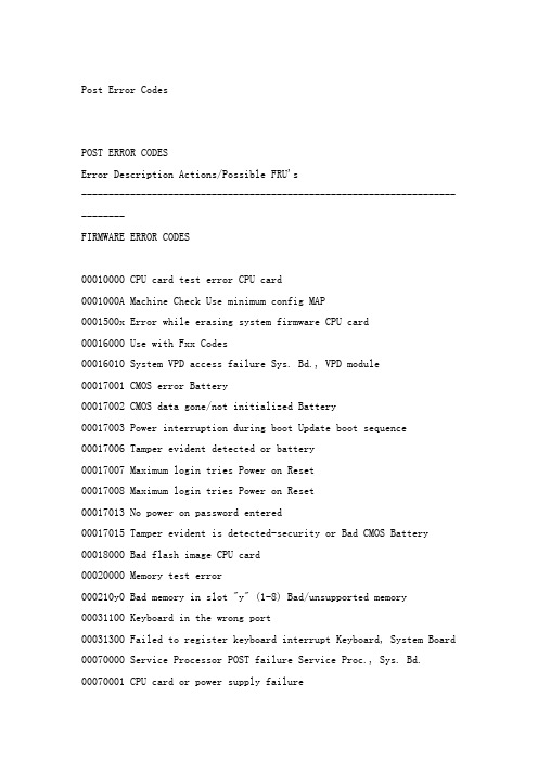
Post Error CodesPOST ERROR CODESError Description Actions/Possible FRU's-----------------------------------------------------------------------------FIRMWARE ERROR CODES00010000 CPU card test error CPU card0001000A Machine Check Use minimum config MAP0001500x Error while erasing system firmware CPU card00016000 Use with Fxx Codes00016010 System VPD access failure Sys. Bd., VPD module00017001 CMOS error Battery00017002 CMOS data gone/not initialized Battery00017003 Power interruption during boot Update boot sequence 00017006 Tamper evident detected or battery00017007 Maximum login tries Power on Reset00017008 Maximum login tries Power on Reset00017013 No power on password entered00017015 Tamper evident is detected-security or Bad CMOS Battery 00018000 Bad flash image CPU card00020000 Memory test error000210y0 Bad memory in slot "y" (1-8) Bad/unsupported memory 00031100 Keyboard in the wrong port00031300 Failed to register keyboard interrupt Keyboard, System Board 00070000 Service Processor POST failure Service Proc., Sys. Bd. 00070001 CPU card or power supply failure00070006 Slow or stuck fan Fans, SP, System Board00070007 System over temperature00070008 Environmental condition Use with Fxx codes00070009 Environmental condition Use with Fxx codes00070010 Environmental condition Use with Fxx codes00070011 Environmental condition Use with Fxx codes00070012 Service processors fails self test Serv. Proc., Sys. Bd. 00070013 Bad NVRAM CRC error Battery, System Board00070014 Bad service processor firmware Re-program firmware 00070015 Bad service processor VPD Serv. Proc., Sys. Bd.00070016 Bad processor firmware failure Firmware update, Serv. Proc. 00070017 Bad or low battery Battery, SP, Sys. Bd.00070018 EPOW test failure Serv. Proc., Sys. Bd.00070019 Interrupt (IRQ13) test failure Sys. Bd., Serv. Proc-----------------------------------------------------------------------------0037cyyi SCSI controller interface error0208cyyi SCSI device/adapter error0210cyyi SCSI DASD error0211cyyi SCSI tape error0215cyyi SCSI CDDROM errorc=SCSI controller ID assigned in the following order:1. PCI slot 12. PCI slot 23. Integrated controller4. PCI slot 35. Continues until last slot...Example: SCSI card slot 2 = ID 0 Integrated SCSI = ID 1SCSI card slot 3 = ID 2Example: Integrated SCSI = ID 0 SCSI card slot 3 = ID 1yy=POST error status codes08 Invalid device number11 No SCSI card13 Command failed28 Reservation conflict29 Device not available43 Not enough memory47 Waiting for completion49 Sense needed51 Reset needed55 Not ready or no media56 Invalid (unsupported) command57 Write protected59 Media error60 Hardware error61 Unit attention62 Blank check63 Command abort64 Busy65 Media66 Script error67 Invalid address68 Media changed69 Device reset70 Format in progress71 Format corrupted72 Start required73 Device ID conflict74 Manual intervention75 Media not found76 In progress77 Media eject failed78 Write protect failed80 SCSI controller interface error81 SCSI controller interface error82 SCSI bus access error83 SCSI fuse bad or PTC tripped84 SCSI device command failed85 SCSI controller interface error86 SCSI controller interface error87 Short record length88 SCSI bus parity error89 SCSI device no reset90 Time out error99 SCSI controller interface error i=SCSI ID (0-9 or A-F)01291000 An error during L2 Cache test CPU card0243025y Graphics controller, DAC failure Grpahics PCI card slot y-----------------------------------------------------------------------------20100xxx Power Supply20A80xxx Remote IPL error20A80000 Insufficient Information to boot Verify IP address20A80001 Client IP address already used Change IP address20A80002 Cannot get gateway IP address Refer to Fxx Boot Problems20A80003 Cannot get server hardware address Refer to Fxx Boot Problems 20A80004 Bootp failed See Checkpoint F7520A80005 File transmission (tftp) failed Check network connection20D00xxx Unknown/Unrecognized device20D0000F Device selftest failure, no SRN Locate device with SMS20D00010 Device selftest failure20E00000 Power on password entry error Wrong password entered20E00001 Privileged-access password entry err. Wrong password entered 20E00002 Privileged-access password jumper is in wrong jumper position 20E00003 Power on password must be set for Unattended Mode20E00004 Battery needs drained or replaced Battery, System Board20E00005 EEPROM locked-Power on reset--or-> Bad System Board20E00008 CMOS corrupted or tampering evident Battery, System Board20E00009 Invalid password entered 3 times Power on reset, System Bd. 20E0000A EEPROM lock problem PAP jumper, System Board20E0000B EEPROM write problem System Board20E0000C EEPROM read problem System Board20E00017 Cold boot needed for password entry Power on reset20EE0xxx Informational20EE0003 IP parameter requires 3 delimiters20EE0004 Invalid IP parameter20EE0005 Invalid IP parameter (>255)20EE0006 No SCSI controllers Adapter, System Board20EE0007 Keybaord not found Keyboard, System Board20EE0008 No adapters found Adapter, Riser, System Bd.21A00xxx SCSI disk drive Device, cable, controller21A00001 Test Unit Ready Failed (hardware) Device, cable, controller 21A00002 Test Unit Ready Failed-sense data Media, device21A00003 Send diagnostic failed Device21A00004 Send diagnostic failed-DevOfl cmd Device21E00xxx SCSI tape21ED0xxx SCSI changer21EE0xxx Other SCSI device21F00xxx SCSI CDROM21F20xxx SCSI Read/Write Optical25010xxx FlashNo diskette in drive Looking for firmware imageDiskette seek errorDiskette doesn't contain *.IMG file Insert firmware update dsktCan't open OPENPROM package System BoardCan't find OPENPROM node System BoardSystem id's don't match Use correct firmware dsktImage has bad CRC Replace firmware dsktFlash write protected-Power on reset System BoardFlash module not supported/recognized Use correct firmware dskt 2501000A Flash write protected-Power on reset System Board25A0xxy0 L2 Cache - refer to 2B2xxyrr CPU, System Board25A80xxx NVRAM Low Battery, Rebuild Config25A80000 Initialization failed25A80001 All NVRAM initialized25A80002 GE area preserved25A80011 Data corruption detected-NVRAM25A80012 Data corruption detected25A80100 NVRAM data validation check failed Power On Reset25AA0xxx EEPROM Security jumper, System Bd.25AA0000 Unable to unlock EEPROM25AA0001 Read-Recv error25AA0002 Read-Trans error25AA0003 Write-enable error25AA0004 Write-recv error25AA0005 Write-disable error25AA0006 Write-Trans error25AA0007 Unable to lock EEPROM-----------------------------------------------------------------------------25Cyyxxx Memory Memory PD25Cyy001 DIMMS fails memory test Memory DIMM25Cyy002 DIMM not supportedyy=Memory DIMM PD bits-----------------------------------------------------------------------------PD Value Size Speed(nsecs) Parity/ECC Single/Dual---------------------------------------------------------------------64 8MB 60 ECC Single69 16MB 60 ECC Single6B 32MB 60 ECC Single6D 64MB 60 ECC Single6F 128MB 60 ECC Single------------------------------------------------------------------------------28030xxx RTC (Real Time Clock) Reset passwords/date/timeRTC not updating RTC needs initializedBad date/time Reset date/timeKeyboard/mouse controller failed System Board29A00003 Keyboard missing Keyboard, System Board29B00004 Mouse missing Mouse, System Board-----------------------------------------------------------------------------2B200042 Unknown processor type2B2xxyrr xx=processor type/speed 21 166Mhz 604+22 200Mhz 604+y=Cache information 0 Integrated cache or N/A5 512KB6 1MB7 256KBD ICBM 1MB2B2xxy22 Bad processor/CPU2B2xxy31 Disabled due to Asymetrical MP---------------------------------------------------------------------2BA00xxx Service Processor (SP)2BA00000 Service Processor POST failure2BA00001 CPU Card or power supply failure2BA00006 FAN error incorrectly reported Fans, Service Proc., Sys Bd. 2BA00007 SP reports over temperature Fans, System Board2BA00008 SP reports over temperature Fans, System Board2BA00009 CPU over temperature Fans, CPU, System Board2BA00010 Fast shutdown pending Power supply, System Board2BA00011 SP reports CPU failure Power supply, System Board2BA00012 SP reports self-test failure Service Proc., System Board2BA00013 SP reports bad NVRAM CRC Battery, System Board2BA00014 SP reports bad processor firmware Rebuild firmware2BA00015 SP reports bad SP VPD Service Proc., System Board2BA00016 SP reports firmware failure Update firmware, Serv. Proc.2BA00017 SP reports bad/low battery Battery, SP, System Board2BA00018 EPOW test failure Serv. Proc., System Board2BA00019 IRQ13 test failure System Board, Serv. Proc.2BA00020 SP reports VPD access failure System Board, VPD module2BA00022 SP reports bad CRC - CMOS/NVRAM System Board2BA00023 CPU card test error CPU card2BA00100 SP firmware recovery info can't be written to diskette2BA00101 Service Processor not installed2BA00102 No SP diskette in drive2BA00103 SP firmware diskette corrupted2BA00104 SP firmware diskette same level2BA00200 SP firmware update error Unplug/Replug-try again2BA00201 SP firmware update error2BA00202 SP firmware update error2BA00203 SP firmware update error2BA00204 SP firmware update error-----------------------------------------------------------------------------Loss of system power detected Power SupplyUnknown power problem Power Supply, Sys Bd, SPHigh voltage Power Supply, CPU cardHigh voltage CPU card, Power SupplyHigh voltage CPU card, Power SupplyHigh +12 voltage Power Supply, Sys. Bd.High -12 voltage Power Supply, Sys. Bd.Low voltage Power Supply, CPU cardLow voltage CPU card, Power Supply401110A2 Low voltage CPU card, Power Supply401110B2 Low +12 voltage Power Supply, Sys. Bd.401110C2 Low -12 voltage Power Supply, Sys. Bd.Unknown cooling problem FansCPU temperature warningCritical CPU temperature warningI/O planar temperature warningCritical I/O planar temperatureMemory temperature warningCritical memory temperatureSlow fanStopped fan40A00000 IPL ROS surveillance interval exceeded-Firmware IPL failure40B00000 Operating system surveillance interval exceeded40D00003 Unknown slow shutdown commanded Critical cooling problem40D00004 Unknown fast shutdown commanded Locked fan failure-----------------------------------------------------------------------------Bad firmware recovery diskette DisketteSame firmware level already loadedFirmware doesn't support systemFirmware update file corruptedFirmware update file not on drive Verify drive/path/filenameFirmware file on disk corrupted Obtain a new fileValid firmware file not located Verify drive/path/filenameFirmware doesn't support system2 Flash images foundFirmware update couldn't be loaded Verify drive/path/filenameFirmware update module write-protect POR, Retry, CPU cardUtility version not supported POR, Retry, CPU cardFirmware module not supported Flash on CPU card badFirmware module not supported Flash on CPU card badFirmware module write-protected POR, Retry, CPU cardBackup recover diskette needed Insert disketteUpdate firmware diskette not in drive Insert disketteService Processor not installed Install Serv. Processor-----------------------------------------------------------------------------Remote IPL error, insufficient memory Defective/insufficient mem. Remote IPL error - incorrect IP format for client IP addressRemote IPL error - incorrect IP format for server IP addressRemote IPL error - incorrect IP format for gateway IP addressRemote IPL error - incorrect IP format for netmaskRemote IPL error - error writing to NVRAMRemote IPL error - ethernet adapter not foundRemote IPL error - token-ring adapter not foundRemote IPL error - no network adapters recognizedRemote IPL error - ping failedM0CON000 System hung during POST Go to minimum configM0CPU000 CPU POST failed CPU Card, System BoardM0CPU001 Checkstop occurred CPU Card, System BoardM0FD0000 System hung during diskette POST System Board, Diskette Drv. M0GA0000 Graphics Adapter POST failed Graphics AdapterM0HD0000 System hung during POST Go to minimum configM0KBD000 System hung during keyboard POST System board, KeyboardM0KBD001 System didn't respond to key entry Type 101 KeyboardM0KBD002 System didn't respond to key entry Type 102 KeyboardM0KBD003 System didn't respond to key entry Type 106 KeyboardM0MC0001 Machine Check Go to minimum configM0MEM000 No good memory found Memory, System BoardM0MEM001 No good memory found Memory, System BoardM0MEM002 System hung during memory POST Go to minimum configM0PS0000 Power failure Go to Power MAPM0SCSI00 Unable to load diagnostics Go to minimum configM0SCSI01 Unable to load diagnostics Go to minimum configM0SPK000 Continuous beep is heard System BoardM0SPK001 The system doesn't beep Speaker, System BoardM0BT0000 Audio error--Use Fxx Code, if none-- Go to minimum configM0NET000 Network error--Use Fxx Code, if none--Go to minimum config POWER5 information第1章Locations — model 561 and 570Map location codes to hardware.1.1Mapping physical location codesNote:The known logical location codes for this unit are listed next to the corresponding physical location in the following information. If you are working with a logical location code for this unit and it is not listed in the following information, contact your next level of support.For address information, see .Use the following illustrations to help you map a location code to a position on the server.Figure 1. Front view of the system unit. P4-D1 and P4–D2 positions are for a 561. The 570 only has the top slot, the P4–D1 location.Figure 2. Back view of the system unitFigure 3. Memory module locations on the processor card (Un-P2-Cx)Use the following illustration to map a node location when you are working with a multiple node installation. All of the nodes have the same location codes inside the system unit; only the serial number is different 4. Multiple node locations with SMP processor cable shownUse the following illustration to help you identify parts of the control panel. Figure 5. A view of the front of the control panel.Number Name Description1Display Displays current status of system startup, ordiagnostic information in the event of ahardware problem.2Front serial port Port uses RJ-45 connector. Use to plug inexternal devices at the front of the systemunit.The following table contains location codes for the parts that make up the server. Attention: After replacing any part on a server or expansion unit, perform .Input/output backplane with embedded:RIOHub/HSL NICRIO/HSLlinkEthernetcontrollerUSBcontroller(AIX® orLinux®only)IDEbridge (AIXor Linux only)SCSI controllers (2)Logic oscillator1.2Input/output adapter (IOA) assignment rules for i5/OS®The following table provides information necessary to identify the input/output processor (IOP) to which IOAs are assigned. The left column indicates the bridge set in which IOA assignment is allowed. Use the right column to determine the IOP to which an IOA is assigned. The first position in the list must be an IOP. The remaining positions might be IOPs or IOAs. IOAs are assigned to the first IOP located to their left in the list. Although IOAs can be manually reassigned using system service tools (SST)/dedicated service tools (DST), the IOA assignments return to the default order after each initial program load (IPL).Parent topic:。
IBM服务器故障指示灯说明
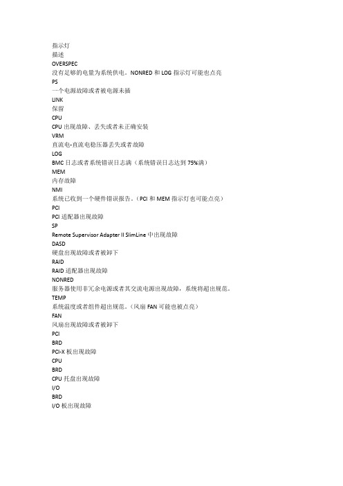
指示灯
描述
OVERSPEC
没有足够的电量为系统供电。
NONRED和LOG指示灯可能也点亮
PS
一个电源故障或者被电源未插
LINK
保留
CPU
CPU出现故障、丢失或者未正确安装
VRM
直流电-直流电稳压器丢失或者故障
LOG
BMC日志或者系统错误日志满(系统错误日志达到75%满)
MEM
内存故障
NMI
系统已收到一个硬件错误报告。
(PCI和MEM指示灯也可能点亮)PCI
PCI适配器出现故障
SP
Remote Supervisor Adapter II SlimLine中出现故障
DASD
硬盘出现故障或者被卸下
RAID
RAID适配器出现故障
NONRED
服务器使用非冗余电源或者其交流电源出现故障,系统将超出规范。
TEMP
系统温度或者组件超出规范。
(风扇FAN可能也被点亮)
FAN
风扇出现故障或者被卸下
PCI
BRD
PCI-X板出现故障
CPU
BRD
CPU托盘出现故障
I/O
BRD
I/O板出现故障。
IBM服务器阵列卡损坏N种情况的解决的方法
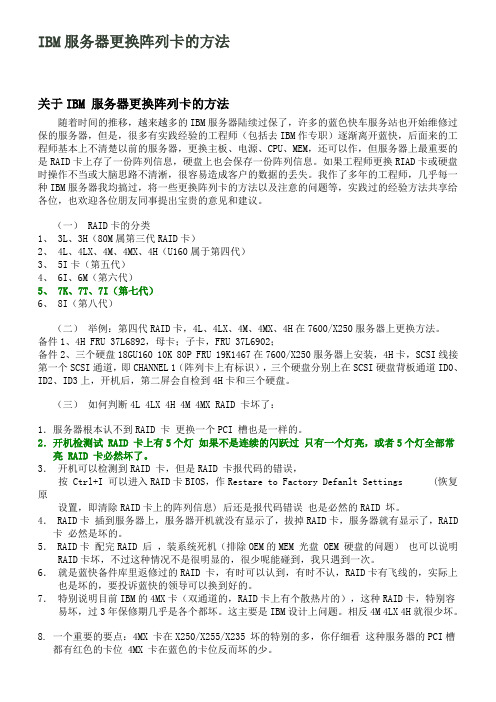
IBM服务器更换阵列卡的方法关于IBM 服务器更换阵列卡的方法随着时间的推移,越来越多的IBM服务器陆续过保了,许多的蓝色快车服务站也开始维修过保的服务器,但是,很多有实践经验的工程师(包括去IBM作专职)逐渐离开蓝快,后面来的工程师基本上不清楚以前的服务器,更换主板、电源、CPU、MEM,还可以作,但服务器上最重要的是RAID卡上存了一份阵列信息,硬盘上也会保存一份阵列信息。
如果工程师更换RIAD卡或硬盘时操作不当或大脑思路不清淅,很容易造成客户的数据的丢失。
我作了多年的工程师,几乎每一种IBM服务器我均搞过,将一些更换阵列卡的方法以及注意的问题等,实践过的经验方法共享给各位,也欢迎各位朋友同事提出宝贵的意见和建议。
(一) RAID卡的分类1、 3L、3H(80M属第三代RAID卡)2、 4L、4LX、4M、4MX、4H(U160属于第四代)3、 5I卡(第五代)4、 6I、6M(第六代)5、 7K、7T、7I(第七代)6、 8I(第八代)(二)举例:第四代RAID卡,4L、4LX、4M、4MX、4H在7600/X250服务器上更换方法。
备件1、4H FRU 37L6892,母卡;子卡,FRU 37L6902;备件2、三个硬盘18GU160 10K 80P FRU 19K1467在7600/X250服务器上安装,4H卡,SCSI线接第一个SCSI通道,即CHANNEL 1(阵列卡上有标识),三个硬盘分别上在SCSI硬盘背板通道ID0、ID2、ID3上,开机后,第二屏会自检到4H卡和三个硬盘。
(三)如何判断4L 4LX 4H 4M 4MX RAID 卡坏了:1.服务器根本认不到RAID 卡更换一个PCI 槽也是一样的。
2.开机检测试 RAID 卡上有5个灯如果不是连续的闪跃过只有一个灯亮,或者5个灯全部常亮 RAID 卡必然坏了。
3.开机可以检测到RAID 卡,但是RAID 卡报代码的错误,按 Ctrl+I 可以进入RAID卡BIOS,作Restare to Factory Defanlt Settings (恢复原设置,即清除RAID卡上的阵列信息) 后还是报代码错误也是必然的RAID 坏。
带MAX5的X3850 X5叠加log灯常亮的解决办法
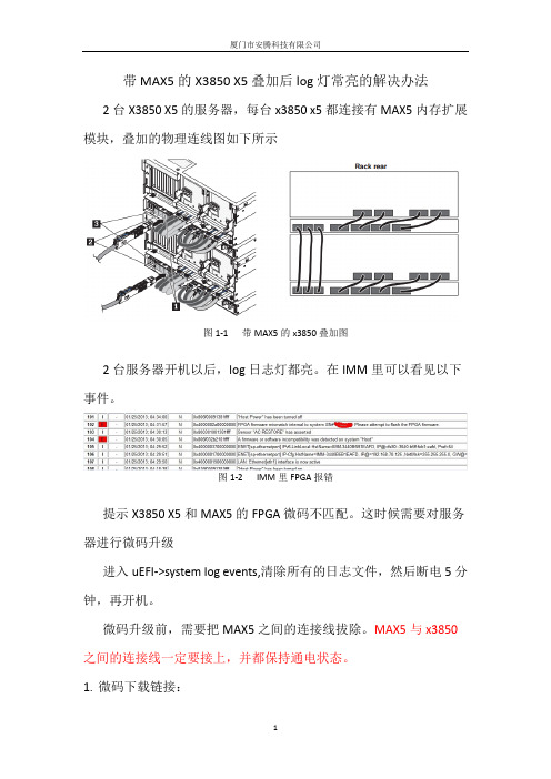
带MAX5的X3850 X5叠加后log灯常亮的解决办法2台X3850 X5的服务器,每台x3850 x5都连接有MAX5内存扩展模块,叠加的物理连线图如下所示图1-1 带MAX5的x3850叠加图2台服务器开机以后,log日志灯都亮。
在IMM里可以看见以下事件。
图1-2 IMM里FPGA报错提示X3850 X5和MAX5的FPGA微码不匹配。
这时候需要对服务器进行微码升级进入uEFI->system log events,清除所有的日志文件,然后断电5分钟,再开机。
微码升级前,需要把MAX5之间的连接线拔除。
MAX5与x3850之间的连接线一定要接上,并都保持通电状态。
1.微码下载链接:1)FPGA微码:ibm_fw_fpga_g0ud81b-2.02_windows_32-64.exe2)IMM微码:ibm_fw_imm_yuood4g-1.32_windows_32-64.exe3)UEFI微码:ibm_fw_uefi_g0e173b-1.73_windows_32-64.exe下载链接:/support/fixcentral/systemx/quickorder?parent=ibm~Systemx3 850X5&product=ibm/systemx/7143&&platform=All&function=fixId&fixids=ibm_fw_f pga_g0ud81b-2.02_windows_32-64,ibm_fw_imm_yuood4g-1.32_windows_32-64,ib m_fw_uefi_g0e173b-1.73_windows_32-64&includeRequisites=1&includeSupersedes =0&downloadMethod=http&source=fc2. 登陆管理口和升级微码的方法如下:请用一台笔记本电脑,一条网线直接连接到服务器的管理口(system management)通过地址:192.168.70.125访问,用户名是:USERID(大写),密码是:PASSW0RD(中间那个0是数字0),连接上之后进入IMM配置界面. 然后选择Tasks——firmware update,点击browse选择本地已经下载好的更新文件,然后点击update,更新完成后重启服务器即可.升级微码注意事项:1)对您硬盘里的重要数据进行备份。
IBM服务器故障诊断及排除

IBM服务器故障诊断及排除⒈引言在日常运维管理中,IBM服务器可能会遇到各种故障,影响业务的正常进行。
本文档旨在提供一套完整的指南,以帮助管理员诊断和排除IBM服务器故障。
本文档将详细介绍故障诊断的步骤以及相关的解决方案。
⒉故障诊断流程⑴收集故障信息●收集服务器硬件信息,包括型号、序列号等。
●收集故障发生时的日志信息,如错误代码、系统日志等。
●收集故障发生的具体环境信息,如温度、湿度等。
⑵分析故障现象●根据故障现象描述,确定故障是否与硬件、软件、网络或其他因素有关。
●分析故障现象的时间、地点、频率等因素,以确定是否存在特定模式。
●使用故障现象和已知信息进行故障推断,缩小故障可能的范围。
⑶验证故障原因●使用合适的测试工具和方法,验证故障的真实原因。
●对可能的故障原因进行排除实验,以确定是否能复现故障。
⑷确定解决方案●基于故障的类型和原因,制定详细的解决方案。
●考虑解决方案的可行性和影响,选择最佳的解决方案。
⑸实施解决方案●根据确定的解决方案,执行相应的操作,修复故障。
●监测修复效果,确保故障得到彻底解决。
⒊常见故障类型及解决方案⑴电源故障●故障现象:服务器无法开机或突然关机。
●可能原因:电源供应问题、电源线路故障等。
●解决方案:检查电源线路和连接器是否正常,更换故障电源。
⑵硬盘故障●故障现象:无法识别硬盘、读写错误等。
●可能原因:硬盘损坏、连接问题等。
●解决方案:检查硬盘连接状态,更换损坏的硬盘。
⑶内存故障●故障现象:系统崩溃、应用程序错误等。
●可能原因:内存故障、内存插槽问题等。
●解决方案:进行内存测试,更换故障内存。
⒋附件本文档涉及以下附件:●附件1:IBM服务器型号和序列号清单●附件2:故障现象记录表●附件3:解决方案实施记录表⒌法律名词及注释●故障:指服务器在运行过程中出现的异常现象,影响服务器的正常工作。
●排除:指针对故障进行诊断和解决的过程,以使服务器恢复正常工作。
IBM 800 技术支持的错误代码对照表
本文代码不针对具体机型---------- Dump Progress Indicator ----------0c0 The dump completed successfully0c1 The dump failed due to an I/O error.0c2 A user-requested dump has started. You requested a dump using the SYSDUMPSTART command, a dump key sequence, or the Reset button.0c3 The dump is inhibit0c4 The dump did not complete. A partial dump was written to the dump device. There is not enough space on the dump deviceto contain the entire dump. To prevent this problem from occuring again, you must increase the size of your dumpmedia.0c5 The dump failed to start. An unecpected error occured while the system was attempting to write to the dump media.0c6 A dump to the secondary dump device was requested. Make the secondary dump device ready, then press CTRL-ALT-NUMPAD2.0c7 Reserved.0c8 The dump function is disabled. No primary dump device is configured.0c9 A dump is in progress.0cc Unknown dump failure---------- Diagnostics Load Progress Indicators -----------c00 AIX Install/Maintenance loaded successfully.c01 Insert the first diagnostic diskette.c02 Diskettes inserted out of sequence.c03 The wrong diskette is in the drive.c04 The loading stopped with an irrecoverable error.c05 A diskette error occurred.c08 RAM filesystem started incorrectly.c07 Insert the next diagnostic diskette.c09 The diskette drive is reading or writing a diskette.c20 An unexpected halt occured, and the system is configured to enter the kernel debug program instead of entering asystem dump.c21 The 'ifconfig' command was unable to configure the network for the client network host.c22 The 'tftp' command was unable to read client's file during a client network boot.c24 Unable to read client's file during a client network boot.c25 Client did not mount remote miniroot during network install.c26 Client did not mount the /usr filesystem during the network boot.c29 System was unable to configure the network device.c31 Select the console display for the diagnostics. To select "No console display", set the key mode switch to normal thento Service. The diagnostic program will then load and run the diagnostics automatically.c32 A direct-attached display (HFT) was selected.c33 a TTY terminal attached to serial ports S1 or S2 was selected.c34 A file was selected. The console messages store in a filec40 Configuration files are been restored.c41 Could not determine the boot type or device.c42 Extracting data files from diskette.c43 Diagboot cannot be accessed.c44 Initialyzing installation database with target disk information.c45 Cannot configure the console.c46 Normal installation processing.c47 Could not create a physical volume identifier (PVID) on disk.c48 Prompting you for input.c49 Could not create or form the JFS log.c50 Creating rootvg volume group on target diskc51 No paging space were found.c52 Changing from RAM environment to disk environment.c53 Not enough space in the /tmp directory to do a preservation installation.c54 Installing either BOS or additionnal packages.c55 Could not remove the specified logical volume in a preservation installation.c56 Running user-defined customization.c57 Failure to restore BOS.c58 Display message to turn the key.c59 Could not copy either device special files, device ODM, or volume group information from RAM to disk.c61 Failed to create the boot image.c70 Problem Mounting diagnostics CDROM disc.c99 Diagnostics have completed. This code is only used when there is no console.--------Debugger Progress Indicators ----------c20 Kernel debug program activated. An unexpected system halt has occured, and you have configured the systemto enter the kernel debug program instead of performing a dump.---------Built-In Self Test (Bist) Indicators---------100 BIST completed successfully. Control was passed to IPL ROS. 101 BIST started following RESET102 BIST started following Power-on Reset103 BIST could not determine the system model number.104 Equipment conflict. BIST could not find the CBA.105 BIST could not read the OCS EPROM.106 BIST detected a module error.111 OCS stopped. BIST detected a module error.112 A checkstop occured during BIST.113 BIST checkstop count is greater than 1.120 BIST starting a CRC check on the 8752 EPROM.121 BIST detected a bad CRC in the first 32K of the OCS EPROM. 122 BIST started a CRC check on the first 32K of the OCS EPROM. 123 BIST detected a bad CRC on the OCS area of NVRAM.124 BIST started a CRC check on the OCS area of NVRAM.125 BIST detected a bad CRC on the time-of-day area of NVRAM. 126 BIST started a CRC check on the time-of-day area of the NVRAM. 127 BIST detected a bad CRC on the 8752 EPROM.130 BIST presence test started.140 BIST failed: procedure error142 BIST failed: procedure error143 Invalid memory configuration.144 BIST failed; procedure error.151 BIST started AIPGM test code.152 BIST started DCLST test code.153 BIST started ACLST test code.154 BIST started AST test code.160 Bad EPOW Signal/Power status signal161 BIST being conducted on BUMP I/O162 BIST being conducted on JTAG163 BIST being conducted on Direct I/O164 BIST being conducted on CPU165 BIST being conducted on DCB and Memory166 BIST being conducted on interrupts170 BIST being conducted on 'Multi-Processor180 BIST logout failed.182 BIST COP bus not responding185 A checkstop condition occured during the BIST186 System logic-generated checkstop (Model 250 only)187 Graphics-generated checkstop (Model 250)195 BIST logout completed.888 BIST did not start------- Power-On Self Test -------200 IPL attempted with keylock in the SECURE position.201 IPL ROM test failed or checkstop occured (irrecoverable)202 IPL ROM test failed or checkstop occured (irrecoverable)203 Unexpected data storage interrupt.204 Unexpected instruction storage interrupt.205 Unexpected external interrupt.206 Unexpected alignment interrupt.207 Unexpected program interrupt.208 Unexpected floating point unavailable interrupt.209 Unexpected SVC interrupt.20c L2 cache POST error. (The display shows a solid 20c for 5 seconds210 Unexpected SVC interrupt.211 IPL ROM CRC comparison error (irrecoverable).212 RAM POST memory configuration error or no memory found (irrecoverable).213 RAM POST failure (irrecoverable).214 Power status register failed (irrecoverable).215 A low voltage condition is present (irrecoverable).216 IPL ROM code being uncompressed into memory.217 End of bootlist encountered.218 RAM POST is looking for 1M bytes of good memory.219 RAM POST bit map is being generated.21c L2 cache is not detected. (The display shows a solid 21c for 5 sec)220 IPL control block is being initialized.221 NVRAM CRC comparison error during AIX.IPL(Key Mode Switch in Normal mode).Reset NVRAM by reaccomplishing IPL in Service mode. For systems with an internal, direct-bus-attached(DBA)disk,IPLROM attempted to perform an IPL from that disk before halting with this three-digit display value.222 Attempting a Normal mode IPL from Standard I/O planar attached devices specified in NVRAM IPL Devices List.223 Attempting a Normal mode IPL from SCSI attached devices specified in NVRAM IPL Devices List.Note: May be caused by incorrect jumper setting for external SCSI devices or by incorrect SCSI terminator.REFER FFC B88224 Attempting a Normal mode restart from 9333 subsystem device specified in NVRAM device list.225 Attempting a Normal mode IPL from IBM 7012 DBA disk attached devices specified in NVRAM IPL Devices List.226 Attempting a Normal mode restart from Ethernet specified in NVRAM device list.227 Attempting a Normal mode restart from Token Ring specified in NVRAM device list.228 Attempting a Normal mode IPL from NVRAM expansion code.229 Attempting a Normal mode IPL from NVRAM IPL Devices List; cannot IPL from any of the listed devices, or there areno valid entry in the Devices List.22c Attempting a normal mode IPL from FDDI specified in NVRAM IPL device list.230 Attempting a Normal mode restart from adapter feature ROM specified in IPL ROM devices list.231 Attempting a Normal mode restart from Ethernet specified in IPL ROM devices list.232 Attempting a Normal mode IPL from Standard I/O planar attached devices specified in Rom Default Device List.233 Attempting a Normal mode IPL from SCSI attached devices specified in IPL ROM Default Device List.234 Attempting a Normal mode restart from 9333 subsystem device specified in IPL ROM device list.235 Attempting a Normal mode IPL from IBM 7012 DBA disk attached devices specified in IPL ROM Default Device List.236 Attempting a Normal mode restart from Ethernet specified in IPL ROM default devices list.237 Attempting a Normal mode restart from Token Ring specified in IPL ROM default device list.238 Attempting a Normal mode restart from Token Ring specified by the operator.239 System failed to restart from the device chosen by the operator.23c Attempting a normal mode IPL from FDDI specified in IPL ROM device list.240 Attempting a Service mode restart from adapter feature ROM.241 Attempting a Normal mode IPL from devices specified in the NVRAM IPL Devices List. 242 Attempting a Service mode IPL from Standard I/O planar attached devices specified in NVRAM IPL Devices List.243 Attempting a Service mode IPL from SCSI attached devices specified in NVRAM IPL Devices List.244 Attempting a Service mode restart from 9333 subsystem device specified in NVRAM device list.245 Attempting a Service mode IPL from IBM 7012 DBA disk attached devices specified in NVRAM IPL Devices List.246 Attempting a Service mode restart from Ethernet specified in NVRAM device list.247 Attempting a Service mode restart from Token Ring specified in NVRAM device list.248 Attempting a Service mode IPL from NVRAM expansion code.249 Attempting a Service mode IPL from NVRAM IPL Devices List; cannot IPL from any of the listed devices, or there areno valid entries in the Devices List.24c Attempting a service mode IPL from FDDI specified in NVRAM IPL device list.250 Attempting a Service mode restart from adapter feature ROM specified in IPL ROM device list.251 Attempting a Service mode restart from Ethernet specified in IPL ROM device list.252 Attempting a Service mode IPL from standard I/O planar attached devicesspecified inROM Default Device List.253 Attempting a Service mode IPL from SCSI attached devices specified in IPL ROM Default Device List.254 Attempting a Service mode restart from 9333 subsystem device specified in IPL ROM device list.255 Attempting a Service mode IPL from IBM 7012 DBA disk'attached devices specified in IPL ROM Default Devices List.256 Attempting a Service mode restart from Ethernet specified in IPL ROM default device list.257 Attempting a Service mode restart from Token Ring specified in IPL ROM default device list.258 Attempting a Service mode restart from Token Ring specified by the operator.259 Attempting a Service mode restart from FDDI specified by the operator.25c Attempting a normal mode IPL from FDDI specified in IPL ROM device list.260 Information is being displayed on the display console.261 Information will be displayed on the tty terminal when the "1" key is pressed on the tty terminal keyboard.262 A keyboard was not detected as being connected to the system'sNOTE: Check for blown planar fuses or for a corrupted boot on disk drive263 Attempting a Normal mode restart from adapter feature ROM specified in NVRAM device list.269 Stalled state - the system is unable to IPL271 Mouse port POST.272 Tablet port POST.277 Auto Token-Ring LANstreamer MC 32 Adapter278 Video ROM Scan POST.279 FDDI adapter POST.280 3COM Ethernet POST.281 Keyboard POST executing.282 Parallel port POST executing283 Serial port POST executing284 POWER Gt1 graphadapte POST executing285 POWER Gt3 graphadapte POST executing286 Token Ring adapter POST executing.287 Ethernet adapter POST executing.288 Adapter card slots being queried.289 GTO POST.290 IOCC POST error (irrecoverable).291 Standard I/O POST running.292 SCSI POST running.293 IBM 7012 DBA disk POST running.294 IOCC bad TCW SIMM in slot location J being tested.295 Graphics Display adapter POST, color or grayscale.296 ROM scan POST.297 System model number does not compare between OCS and ROS(irrecoverable). Attempting a software IPL.298 Attempting a software IPL (warm boot).299 IPL ROM passed control to the loaded program code.301 Flash Utility ROM failed or checkstop occured (irrecoverable)302 Flash Utility ROM failed or checkstop occured (irrecoverable)302 Flash Utility ROM: User prompt, move the key to the service in order to perform an optional Flash Update. LEDwill only appear if the key switch is in the SECURE position. This signals the user that a Flash Update may beinitiated by moving the key switch to the SERVICE position. If the key is moved to the SERVICE position,LED 303 will be displayed. This signals the user to press the reset button and select optional Flash Update.303 Flash Utility ROM: User prompt, press the reset button in order to perform an optional Flash Update. LEDonly appear if the key switch is in the SECURE position. This signals the user that a Flash Update may be initiatedby moving the key switch to the SERVICE position. If the key is moved to the SERVICE position, LED 303 will bedisplayed. This signals the user to press the reset button and select optional Flash Update. 304 Flash Utility ROM IOCC POST error (irrecoverable)305 Flash Utility ROM standard I/O POST running.306 Flash Utility ROM is attempting IPL from Flash Update Boot Image.307 Flash Utility ROM system model number does not compare between OCS and ROM (irrecoverable).308 Flash Utility ROM: IOCC TCW memory is being tested.309 Flash Utility ROM passed control to a Flash Update Boot Image.311 Flash Utility ROM CRC comparison error (irrecoverable).312 Flash Utility ROM RAM POST memory configuration error or no memory found ( iirecoverable).313 Flash Utility ROM RAM POST failure( irrecoverable).314 Flash Utility ROM Power status register failed (irrecoverable).315 Flash Utility ROM detected a low voltage condition.318 Flash Utility ROM RAM POST is looking for good memory.319 Flash Utility ROM RAM POST bit map is being generated.322 CRC error on media Flash Image. No Flash Update performed.323 Current Flash Image is being erased.324 CRC error on new Flash Image after Update was performed. (Flash Image is corrupted). 325 Flash Image successful and complete.500 Querying Native I/O slot.501 Querying card in Slot 1502 Querying card in Slot 2503 Querying card in Slot 3504 Querying card in Slot 4505 Querying card in Slot 5506 Querying card in Slot 6507 Querying card in Slot 7508 Querying card in Slot 8510 Starting device configuration.511 Device configuration completed.512 Restoring device configuration files from media.513 Restoring basic operating system installation files from media.516 Contacting server during network boot517 Mounting client remote file system during network IPL.518 Remote mount of the root and /usr filesystems failed during network boot.520 Bus configuration running.521 /etc/init invoked cfgmgr with invalid options; /etc/init has been corrupted or incorrectly modified(irrecoverable error).522 The configuration manager has been invoked with conflicting options (irrecoverable error).523 The configuration manager is unable to access the ODM database (irrecoverable error). 524 The configuration manager is unable to access the config rules object in the ODM database (irrecoverable error).525 The configuration manager is unable to get data from a customized device object in the ODM database(irrecoverable error).526 The configuration manager is unable to get data from a customized device driver objet in the ODM database(irrecoverable error).527 The configuration manager was invoked with the phase 1 flag; running phase 1 flag; running phase 1 at this pointis not permitted (irrecoverable error).528 The configuration manager cannot find sequence rule, or no program was specified in the ODM database(irrecoverable error).529 The configuration manager is unable to update ODM data(irrecoverable error).530 The program "savebase" returned an error.531 The configuration manager is unable to access PdAt object class(irrecoverable eroor)532 There is not enough memory to continue (malloc failure);irrecoverable error.533 The configuration manager could not find a configure method for a device.534 The configuration manager is unable to aquire database lock. irrecoverable error.536 The configuration manager encountered more than one sequence rule specified in the same phase. (irrecoverable error).537 The configuration manager encountered an error when invoking the program in the sequence rule.538 The configuration manager is going to invoke a configuration539 The configuration method has terminated, and control has returned to the configuration manager.551 IPL Varyon is running552 IPL Varyon failed.553 IPL phase 1 is complete.554 Unable to define NFS swap device during network boot555 Unable to define NFS swap device during network boot556 Logical Volume Manager encountered error during IPL varyon.557 The root filesystem will not mount.558 There is not enough memory to continue the IPL.559 Less than 2MB of good memory are available to load the AIX kernel.570 Virtual SCSI devices being configured.571 HIPPI common function device driver being configured.572 HIPPI IPI-3 master transport driver being configured.573 HIPPI IPI-3 slave transport driver being configured.574 HIPPI IPI-3 transport services user interface device driver being configured.576 Generic async device driver being configured.577 Generic SCSI device driver being configured.578 Generic commo device driver being configured.579 Device driver being configured for a generic device.580 HIPPI TCPIP network interface driver being configured.581 Configuring TCP/IP.582 Configuring token ring data link control.583 Configuring an Ethernet data link control.584 Configuring an IEEE ethernet data link control.585 Configuring an SDLC MPQP data link control.586 Configuring a QLLC X.25 data link control.587 Configuring NETBIOS.588 Configuring a Bisync Read-Write (BSCRW).589 SCSI target mode device being configured.590 Diskless remote paging device being configured.591 Configuring an LVM device driver592 Configuring an HFT device driver593 Configuring SNA device drivers.594 Asynchronous I/O being defined or configured.595 X.31 pseudo device being configured.596 SNA DLC/LAPE pseudo device being configured.597 OCS software being configured.598 OCS hosts being configured during system reboot.599 Configuring FDDI data link control.5c0 Streams-based hardware drive being configured.5c1 Streams-based X.25 protocol being configured.5c2 Streams-based X.25 COMIO emulator driver being configured.5c3 Streams-based X.25 TCP/IP interface driver being configured.5c4 FCS adapter device driver being configured.5c5 SCB network device driver for FCS is being configured.5c6 AIX SNA channel being configured.600 Starting network boot portion of /sbin/rs.boot602 Configuring network parent devices.603 /usr/lib/methods/defsys/usr/lib/methods/cggsys, or/usr/lib/methods/cggbus failed.604 Configuring physical network boot device.605 Configuring physical network boot device failed.606 Running /usr/sbin/ifconfig on logical network boot device.607 /usr/sbin/ifconfig failed.608 Attempting to retrieve the file with tftp. Note that a flashing 608 indicates multiple attemptsto retrieve the client_info file are occuring.609 The file does not exist or it is zero length.610 Attempting remote mount of NFS file system611 Remote mount of the NFS filesystem failed.612 Accessing remote files; unconfiguring network boot device.614 Configuring local paging devices.615 Configuring of a local paging device failed.616 Converting from diskette to dataless configuration.617 Diskless to dataless configuration failed.618 Configuring remote (NFS) paging devices.619 Configuration of a remote (NFS) paging device failed.620 Updating special device files and ODM in permanent filesystem with data from boot RAM filesystem.622 Boot process configuring for operating system installation.650 IBM SCSD disk drive drive being configured700 Progress indicator. A 1.1GB 8-bit SCSI disk drive being identified or configured.701 Progress indicator. A 1.1GB 16-bit SCSI SE disk drive being identified or configured. 702 Progress indicator. A 1.1GB 16-bit SCSI differential disk drive being identified or configured.703 Progress indicator. A 2.2GB 8-bit SCSI disk drive being identified or configured.704 Progress indicator. A 2.2GB 16-bit SCSI SE disk drive being identified or configured. 705 The configuration method for the 2.2GB 16-bit differential SCSI disk drive is being run. If a irrecoverableerror occurs, the system halts. identified or configured.706 Progress indicator. A 4.5GB 16-bit SE SCSI disk drive is being identified or configured. 707 Progress indicator. A 4.5GB 16-bit differential SCSI drive is being identified or configured.708 Progress indicator: A L2 cache is being identified or configured.710 POWER GXT150M graphics adapterbeing ientifyied or configured.711 Unknown adapter being identified or configured.712 Graphics slot bus configuration is executing.713 The IBM ARTIC960 device is being configured.714 A video capture adapter is being configured.715 The Ultimedia Services audio adapter is being configured. This LED displays briefly on the panel.720 Unknown read/write optical drive type being configured.721 Unknown disk or SCSI device being identified or configured.722 Unknown disk being identified or configured.723 Unknown CDROM being identified or configured.724 Unknown tape drive being identified or configured.725 Unknown display being identified or configured.726 Unknown input device being idenor configuredknown adync device being idenor configured727 Un。
计算机技术知识问与答
1:如何为ibm x服务器配置阵列?对于8k,8i,8k-l也有三种配置方法:1、用随卡代的ServeRAID Support CD启动进行配置。
配置方法如下:当您从可引导的IBM ServeRAID Support CD引导进入ServeRAID Manager程序时,您正在使用的是CD引导启动模式。
这种方式可以在安装操作系统前配置控制器。
安装完操作系统后,仍然可以使用CD引导启动模式对控制器进行设置更改。
“更多信息请参阅优化配置章节”要使用CD引导启动模式运行ServeRAID Manager程序,打开服务器,插入IBM ServeRAID Support CD (或随服务器附送的包含ServeRAID Manager程序的CD)到CD-ROM 驱动器中。
当ServeRAID Manager 程序检测到未配置的控制器和就绪的驱动器时,程序会自动启动配置向导,窗口类似于下图5。
图5 配置向导窗口您可以利用向导模式为ServeRAID 控制器创建逻辑驱动器。
配置向导模式提供两种配置选项:Express(快速)和Custom(自定义)。
快速配置可以自动配置ServeRAID控制器。
用户自定义配置为手工方式配置。
如果您需要配置RAID 1E ,5EE(仅8i支持),6或是X0级别阵列,必须使用用户自定义配置选项。
更多关于RAID级别信息,请参阅IBM ServeRAID Support CD 用户手册“RAID 技术概览”章节。
使用快速配置Express 配置方式自动配置ServeRAID 控制器。
如下:●将相同容量的一组盘创建逻辑盘●对一组物理盘构成的逻辑盘分配RAID级别-两个物理盘组成的逻辑盘可以分配RAID 1-三个或三个以上物理盘组成的逻辑盘可以分配RAID 5按如下步骤完成Express 配置方式:1.在ServeRAID Manager 树中点击想要配置的ServeRAID controller。
IBM服务器LED告警解释
RS/6000液晶显示屏上显示代码(LED)的含义本文介绍RS/6000启动过程中机器上的液晶显示屏代码的含义。
本文代码不针对具体机型。
IPL ROM CRC comparison error (irrecoverable).RAM POST memory configuration error or no memory found (irrecoverable).RAM POST failure (irrecoverable).Power status register failed (irrecoverable).A low voltage condition is present (irrecoverable).IPL ROM code being uncompressed into memory.End of bootlist encountered.RAM POST is looking for 1M bytes of good memory.RAM POST bit map is being generated.L2 cache is not detected. (The display shows a solid 21c for 5 sec)IPL control block is being initialized.NVRAM CRC comparison error during AIX.IPL(Key Mode Switch in Normal mode).Reset NVRAM by reaccomplishing IPL in Service mode. For systems with an internal, direct-bus-attached(DBA)disk,IPLROM attempted to perform an IPL from that disk before halting with this three-digit display value. Attempting a Normal mode IPL from Standard I/O planar attached devices specified in NVRAM IPL Devices List.Attempting a Normal mode IPL from SCSI attached devices specified in NVRAM IPL Devices List.Note: May be caused by incorrect jumper setting for external SCSI devices or by incorrect SCSI terminator.REFER FFC B88Attempting a Normal mode restart from 9333 subsystem device specified in NVRAM device list. Attempting a Normal mode IPL from IBM 7012 DBA disk attached devices specified in NVRAM IPL Devices List.Attempting a Normal mode restart from Ethernet specified in NVRAM device list.Attempting a Normal mode restart from Token Ring specified in NVRAM device list. Attempting a Normal mode IPL from NVRAM expansion code.Attempting a Normal mode IPL from NVRAM IPL Devices List; cannot IPL from any of the listed devices, or there areno valid entry in the Devices List.Attempting a normal mode IPL from FDDI specified in NVRAM IPL device list.Attempting a Normal mode restart from adapter feature ROM specified in IPL ROM devices list. Attempting a Normal mode restart from Ethernet specified in IPL ROM devices list.Attempting a Normal mode IPL from Standard I/O planar attached devices specified in Rom Default Device List.Attempting a Normal mode IPL from SCSI attached devices specified in IPL ROM Default Device List.Attempting a Normal mode restart from 9333 subsystem device specified in IPL ROM device list. Attempting a Normal mode IPL from IBM 7012 DBA disk attached devices specified in IPL ROM Default Device List.Attempting a Normal mode restart from Ethernet specified in IPL ROM default devices list. Attempting a Normal mode restart from Token Ring specified in IPL ROM default device list. Attempting a Normal mode restart from Token Ring specified by the operator.System failed to restart from the device chosen by the operator.Attempting a normal mode IPL from FDDI specified in IPL ROM device list.Attempting a Service mode restart from adapter feature ROM.Attempting a Normal mode IPL from devices specified in the NVRAM IPL Devices List.Unknown tape drive being identified or configured. Unknown display being identified or configured. Unknown input device being idenor configuredUnknown adync device being idenor configured。
IMB报错大全
(Resume error.)
1. System board.
1XX
1. System board.
2XX(内存问题)
201: Memory data error.
202: Memory line error 00-15.
203: Memory line error 16-23.
205: Memory test failure on on-board
1. Go to Diskette Drive Checkout
2. Diskette.
3. Diskette drive assembly.(软驱有没有装配好?)
604
(Unacceptable ID was read from the diskette drive.);
1. Go to Diskette Drive Checkout
2. Hard disk drive assembly.
3. System board.
175, 177, 178
175: EEPROM CRC #1 error.
177: Supervisor password check sum error.
178: EEPROM is not functional.
2. System board.(主板问题)
173
(Configuration data was lost.)(CMOS设备配置信息丢失)
1. Select OK in the error screen; then set the time and date.
(在开机ERROR画面上按OK,然后设置系统时间)
158
(Hard disk password was not set even though the supervisor password is set.)(超级用户密码已设,但硬盘密码没有设置)
- 1、下载文档前请自行甄别文档内容的完整性,平台不提供额外的编辑、内容补充、找答案等附加服务。
- 2、"仅部分预览"的文档,不可在线预览部分如存在完整性等问题,可反馈申请退款(可完整预览的文档不适用该条件!)。
- 3、如文档侵犯您的权益,请联系客服反馈,我们会尽快为您处理(人工客服工作时间:9:00-18:30)。
适用机型: 所有服务器
以下报错信息,只是对目前大部分X系列服务器适用的报错信息。仅供参考,如果服务器使用
过程中发生橘黄色感叹号灯常亮,或者服务器停止在自检过程中,建议客户尽快跟IBM技术
服务人员联系。
错误代码/症状 FRU
/操作
062(使用缺省配置的连续三次引导失败。) 1. 运行Configuration/Setup
Utility 程序
2. 电池
3. 主板
4. 微处理器
101、102、106(计时器时标中断失败) * 主板
102(计时器2 测试失败) * 主板
106(软盘控制器错误) * 主板
129(内置高速缓存(L1)错误) 1. 可选微处理器
2. 微处理器
151(实时时钟错误) 1.
电池
2. 主板
161(实时时钟电池错误) 1. 运行Configuration
/Setup Utility 程序
2. 电池
3. 主板
162(设备配置错误)
注:请务必装入缺省设置和任何期望的其它设置;
然后,保存配置 1. 运行Configuration/Se
tup Utility 程序
2. 电池
3. 发生故障的设备
4. 主板
163
(实时时钟错误) 1. 运行Configuration/S
etup Utility 程序
2. 电池
3. 主板
164
(内存配置更改。) 1. 运行Configuration
/Setup Utility 程序
2. DIMM
3. 主板
175
(EEPROM CRC #1 损坏) * 主板
184
(开机密码损坏) 1. 运行Configura
tion/Setup Utility 程序
2. 主板
185