4B06规格书
MEMORY存储芯片MT29F4G08ABADAWP-ITD中文规格书

NAND Flash MemoryMT29F4G08ABADAH4, MT29F4G08ABADAWP, MT29F4G08ABBDAH4, MT29F4G08ABBDAHC, MT29F4G16ABADAH4, MT29F4G16ABADAWP, MT29F4G16ABBDAH4, MT29F4G16ABBDAHC, MT29F8G08ADADAH4,MT29F8G08ADBDAH4, MT29F8G16ADADAH4, MT29F8G16ADBDAH4, MT29F16G08AJADAWPFeatures•Open NAND Flash Interface (ONFI) 1.0-compliant1•Single-level cell (SLC) technology •Organization–Page size x8: 2112 bytes (2048 + 64 bytes)–Page size x16: 1056 words (1024 + 32 words)–Block size: 64 pages (128K + 4K bytes)–Plane size: 2 planes x 2048 blocks per plane–Device size: 4Gb: 4096 blocks; 8Gb: 8192 blocks 16Gb: 16,384 blocks•Asynchronous I/O performance–t RC/t WC: 20ns (3.3V), 25ns (1.8V)•Array performance–Read page: 25µs 3–Program page: 200µs (TYP: 1.8V, 3.3V)3–Erase block: 700µs (TYP)•Command set: ONFI NAND Flash Protocol •Advanced command set–Program page cache mode4–Read page cache mode 4–One-time programmable (OTP) mode–Two-plane commands 4–Interleaved die (LUN) operations–Read unique ID–Block lock (1.8V only)–Internal data move•Operation status byte provides software method for detecting–Operation completion–Pass/fail condition–Write-protect status•Ready/Busy# (R/B#) signal provides a hardware method of detecting operation completion•WP# signal: Write protect entire device •First block (block address 00h) is valid when ship-ped from factory with ECC. For minimum required ECC, see Error Management.•Block 0 requires 1-bit ECC if PROGRAM/ERASE cy-cles are less than 1000•RESET (FFh) required as first command after pow-er-on•Alternate method of device initialization (Nand_In-it) after power up (contact factory)•Internal data move operations supported within the plane from which data is read•Quality and reliability–Data retention: 10 years–Endurance: 100,000 PROGRAM/ERASE cycles •Operating voltage range–V CC: 2.7–3.6V–V CC: 1.7–1.95V•Operating temperature:–Commercial: 0°C to +70°C–Industrial (IT): –40ºC to +85ºC•Package–48-pin TSOP type 1, CPL2–63-ball VFBGANotes: 1.The ONFI 1.0 specification is available at2.CPL = Center parting line.3.See Program and Erase Characteristics fort R_ECC and t PROG_ECC specifications.4.These commands supported only with ECCdisabled.Figure 78: TWO-PLANE BLOCK ERASERE#CE#ALECLE I/Ox R/B#WE#Figure 79: TWO-PLANE/MULTIPLE-DIE READ STATUS CycleCE#CLE ALE RE#I/Ox4Gb, 8Gb, 16Gb: x8, x16 NAND Flash MemoryTwo-Plane OperationsInterleaved Die (Multi-LUN) OperationsIn devices that have more than one die (LUN) per target, it is possible to improve per-formance by interleaving operations between the die (LUNs). An interleaved die (multi-LUN) operation is one that is issued to an idle die (LUN) (RDY = 1) while another die (LUN) is busy (RDY = 0).Interleaved die (multi-LUN) operations are prohibited following RESET (FFh), identifi-cation (90h, ECh, EDh), and configuration (EEh, EFh) operations until ARDY =1 for all of the die (LUNs) on the target.During an interleaved die (multi-LUN) operation, there are two methods to determine operation completion. The R/B# signal indicates when all of the die (LUNs) have finish-ed their operations. R/B# remains LOW while any die (LUN) is busy. When R/B# goes HIGH, all of the die (LUNs) are idle and the operations are complete. Alternatively, the READ STATUS ENHANCED (78h) command can report the status of each die (LUN) in-dividually.If a die (LUN) is performing a cache operation, like PROGRAM PAGE CACHE (80h-15h),then the die (LUN) is able to accept the data for another cache operation when status register bit 6 is 1. All operations, including cache operations, are complete on a die when status register bit 5 is 1.During and following interleaved die (multi-LUN) operations, the READ STATUS (70h)command is prohibited. Instead, use the READ STATUS ENHANCED (78h) command to monitor status. This command selects which die (LUN) will report status. When two-plane commands are used with interleaved die (multi-LUN) operations, the two-plane commands must also meet the requirements in Two-Plane Operations.See Command Definitions for the list of commands that can be issued while other die (LUNs) are busy.During an interleaved die (multi-LUN) operation that involves a PROGRAM series (80h-10h, 80h-15h) operation and a READ operation, the PROGRAM series operation must be issued before the READ series operation. The data from the READ series opera-tion must be output to the host before the next PROGRAM series operation is issued.This is because the 80h command clears the cache register contents of all cache regis-ters on all planes.4Gb, 8Gb, 16Gb: x8, x16 NAND Flash MemoryInterleaved Die (Multi-LUN) OperationsError ManagementEach NAND Flash die (LUN) is specified to have a minimum number of valid blocks(NVB) of the total available blocks. This means the die (LUNs) could have blocks thatare invalid when shipped from the factory. An invalid block is one that contains at leastone page that has more bad bits than can be corrected by the minimum required ECC.Additional blocks can develop with use. However, the total number of available blocksper die (LUN) will not fall below NVB during the endurance life of the product.Although NAND Flash memory devices could contain bad blocks, they can be usedquite reliably in systems that provide bad block management and error-correction algo-rithms. This type of software environment ensures data integrity.Internal circuitry isolates each block from other blocks, so the presence of a bad blockdoes not affect the operation of the rest of the NAND Flash array.NAND Flash devices are shipped from the factory erased. The factory identifies invalidblocks before shipping by attempting to program the bad block mark into every loca-tion in the first page of each invalid block. It may not be possible to program every loca-tion with the bad block mark. However, the first spare area location in each bad block isguaranteed to contain the bad block mark. This method is compliant with ONFI FactoryDefect Mapping requirements. See the following table for the first spare area locationand the bad block mark.System software should check the first spare area location on the first page of eachblock prior to performing any PROGRAM or ERASE operations on the NAND Flash de-vice. A bad block table can then be created, enabling system software to map aroundthese areas. Factory testing is performed under worst-case conditions. Because invalidblocks could be marginal, it may not be possible to recover this information if the blockis erased.Over time, some memory locations may fail to program or erase properly. In order toensure that data is stored properly over the life of the NAND Flash device, the followingprecautions are required:•Always check status after a PROGRAM or ERASE operation•Under typical conditions, use the minimum required ECC (see table below)•Use bad block management and wear-leveling algorithmsThe first block (physical block address 00h) for each CE# is guaranteed to be validwith ECC when shipped from the factory.Table 21: Error Management DetailsTable 21: Error Management Details (Continued)。
Sn64Bi35Ag1无铅锡膏技术规格书
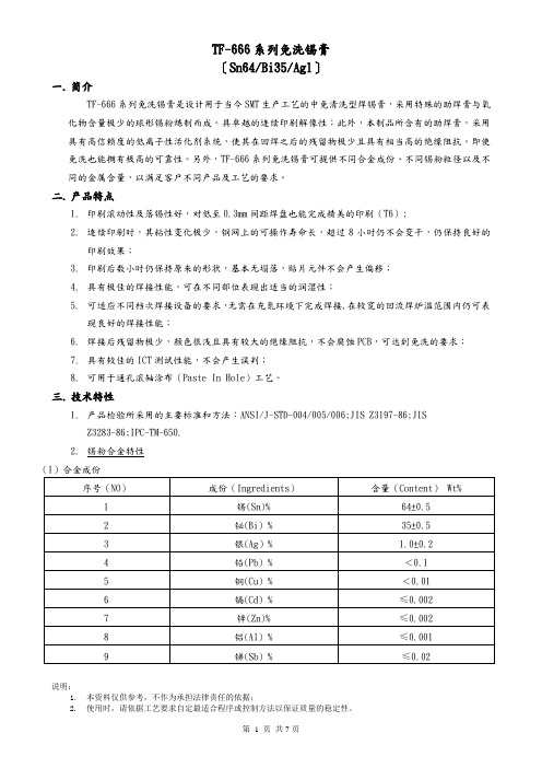
TF-666系列免洗锡膏〔Sn64/Bi35/Ag1〕一.简介TF-666系列免洗锡膏是设计用于当今SMT生产工艺的中免清洗型焊锡膏,采用特殊的助焊膏与氧化物含量极少的球形锡粉炼制而成。
具卓越的连续印刷解像性;此外,本制品所含有的助焊膏,采用具有高信赖度的低离子性活化剂系统,使其在回焊之后的残留物极少且具有相当高的绝缘阻抗。
即使免洗也能拥有极高的可靠性。
另外,TF-666系列免洗锡膏可提供不同合金成份、不同锡粉粒径以及不同的金属含量,以满足客户不同产品及工艺的要求。
二.产品特点1.印刷滚动性及落锡性好,对低至0.3mm间距焊盘也能完成精美的印刷(T6);2.连续印刷时,其粘性变化极少,钢网上的可操作寿命长,超过8小时仍不会变干,仍保持良好的印刷效果;3.印刷后数小时仍保持原来的形状,基本无塌落,贴片元件不会产生偏移;4.具有极佳的焊接性能,可在不同部位表现出适当的润湿性;5.可适应不同档次焊接设备的要求,无需在充氮环境下完成焊接,在较宽的回流焊炉温范围内仍可表现良好的焊接性能;6.焊接后残留物极少,颜色很浅且具有较大的绝缘阻抗,不会腐蚀PCB,可达到免洗的要求;7.具有较佳的ICT测试性能,不会产生误判;8.可用于通孔滚轴涂布(Paste In Hole)工艺。
三.技术特性1.产品检验所采用的主要标准和方法:ANSI/J-STD-004/005/006;JIS Z3197-86;JISZ3283-86;IPC-TM-650.2.锡粉合金特性说明:1.本资料仅供参考,不作为承担法律责任的依据;(4)锡粉形状:球形说明:1.本资料仅供参考,不作为承担法律责任的依据;四.应用1.如何选用本系列锡膏客户可根据自身产品及工艺的要求选择相应的合金成份、锡粉大小及金属含量(查看本资料相关内容)。
2.使用前的准备1)“回温”锡膏通常要用冰箱冷藏,冷藏温度为0-10ºC为佳。
故从冷箱中取出锡膏时,其温度较室温低很多,若未经“回温”,而开启瓶盖,则容易将空气中的水汽凝结,并沾附于锡浆上。
戴尔 Precision 7680 设置和规格 说明书

Precision 7680设置和规格6 2023Identifier GUID-5B8DE7B7-879F-45A4-88E0-732155904029Version15Status Translation approved注意、小心和警告注:“注意”表示可帮助您更好地使用产品的重要信息。
小心:“小心”表示可能会导致硬件损坏或数据丢失,并告诉您如何避免问题。
警告:“警告”表示可能会导致财产损坏、人身伤害甚至死亡。
© 2023 Dell Inc. 或其子公司。
保留所有权利Dell Technologies、Dell 和其他商标均是 Dell Inc. 或其子公司的商标。
其他商标可能是其各自所有者的商标。
章 1: 设置 Precision 7680 (5)章 2: Precision 7680的视图 (7)右 (7)左侧 (8)顶部 (9)显示屏 (10)底部 (11)服务编号 (11)电池电量和状态指示灯 (12)章 3: Precision 7680 的规格 (13)尺寸和重量 (13)处理器 (13)芯片组 (14)操作系统 (14)内存 (15)外部端口 (16)内部插槽 (16)以太网 (17)无线模块 (17)WWAN 模块 (18)音频 (18)存储 (19)RAID(独立磁盘冗余阵列) (19)介质卡读取器 (20)键盘 (20)摄像头 (21)触控板 (21)电源适配器 (22)电池 (23)显示屏 (24)指纹读取器 (25)传感器 (25)GPU —集成 (26)多显示屏支持值表 (26)GPU —独立 (26)多显示屏支持矩阵 (27)硬件安全性 (27)智能卡读卡器 (28)非接触式智能卡读卡器 (28)接触式智能卡读卡器 (29)操作和存储环境 (30)目录3章 4: Precision 7680的键盘快捷键 (31)章 5: 获取帮助和联系戴尔 (33)4目录IdentifierGUID-0BECE3E8-1013-48D2-B0A9-F9425A4526CD Version4StatusTranslation Validated设置 Precision 7680关于此任务注: 根据您所订购的配置,本文档中的图像可能与您的计算机有所差异。
BLF6G21-10G,135;中文规格书,Datasheet资料

PL(AV) = 0.7 W
-
−50 -
dBc
Table 8. Application information Mode of operation: 1-carrier W-CDMA; PAR 7.5 dB at 0.01 % probability on CCDF; 3GPP test model 1; 1-64 PDPCH; f1 = 2112.5 MHz; f2 = 2167.5 MHz; RF performance at VDS = 28 V; IDq = 100 mA; Tcase = 25 °C; unless otherwise specified; in a class-AB production test circuit.
I Easy power control I Integrated ESD protection I Excellent ruggedness I High efficiency
/
NXP Semiconductors
BLF6G21-10G
Power LDMOS transistor
test model 1; 1-64 PDPCH; f1 = 2112.5 MHz; f2 = 2117.5 MHz; f3 = 2162.5 MHz; f4 = 2167.5 MHz; RF performance at VDS = 28 V; IDq = 100 mA; Tcase = 25 °C; unless otherwise specified; in a class-AB production test circuit.
Table 4. Limiting values In accordance with the Absolute Maximum Rating System (IEC 60134).
MMBT2222A;中文规格书,Datasheet资料
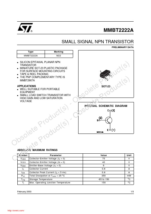
MMBT2222ASMALL SIGNAL NPN TRANSISTORPRELIMINARY DATAsSILICON EPITAXIAL PLANAR NPNTRANSISTORs MINIATURE SOT-23 PLASTIC PACKAGE FOR SURFACE MOUNTING CIRCUITS s TAPE & REEL PACKINGsTHE PNP COMPLEMENTARY TYPE IS MMBT2907AAPPLICATIONS s WELL SUITABLE FOR PORTABLE EQUIPMENTs SMALL LOAD SWITCH TRANSISTOR WITH HIGH GAIN AND LOW SATURATION VOLTAGEFebruary 2003ABSOLUTE MAXIMUM RATINGS®1/5e t e P r o d u c t (s ) - O b s o l e t e P r o d u c t (s ) -MMBT2222ATHERMAL DATAELECTRICAL CHARACTERISTICS (T case = 25 o C unless otherwise specified)Ob s o l e t e P r o d uc t (s ) - O b s o l e t e P r od u c t (s ) ELECTRICAL CHARACTERISTICS(Continued)MMBT2222AO b s o l e t e P r o d u c t (s ) - O b s o l e t e P r o d u c t (s )MMBT2222AOb s o l e t e P r o d uc t (s ) - O b s o l e t e P r od u c t (s ) Information furnished is believed to be accurate and reliable. However, STMicroelectronics assumes no responsibility for the consequences of use of such information nor for any infringement of patents or other rights of third parties which may result from its use. No license is granted by implication or otherwise under any patent or patent rights of STMicroelectronics. Specification mentioned in this publication are subject to change without notice. This publication supersedes and replaces all information previously supplied. STMicroelectronics products are not authorized for use as critical components in life support devices or systems without express written approval of STMicroelectronics.The ST logo is a trademark of STMicroelectronics© 2003 STMicroelectronics – Printed in Italy – All Rights ReservedSTMicroelectronics GROUP OF COMPANIESAustralia - Brazil - Canada - China - Finland - France - Germany - Hong Kong - India - Israel - Italy - Japan - Malaysia - Malta - Morocco - Singapore - Spain - Sweden - Switzerland - United Kingdom - United States.MMBT2222AO b s o l e t e P r o d u c t (s ) - O b s o l e t e P r o d u c t (s )分销商库存信息: STMMMBT2222A。
产品规格书
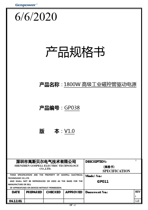
本电源为专为工业应用场合设计的高档智能磁控管驱动电源,采用高压和灯丝分开方案,前级采用
设计,高压部分和灯丝部分集成在本电源板上,额定输入电压为200-240Vac,
可选)标准接口,能与个人计算机、PLC或同系列的RS-485
连接,进行主从式、异步半双工串行通信。
可由通讯端口控制输出功率,在最大功率范围内进行调节,本电源具有多重保护功能,能够适应于不同
规格的磁控管驱动,该电源特别适应于高性能微波炉磁控管驱动,具有高效率,低
本电源为模块式结构,可以作为独立的模块接磁控管运行,也可以多台并机工作,通过通讯端口控制。
采用专利技术,软开关特性,高压部分和灯丝部分均为软开关,高效率,低。
0.5mm翻盖FPC座子规格书
completion of the exposure period,
the test specimens shall be
conditioned at ambient room 接触阻抗
conditions for 1 to 2 hours, after which the specified measurements shall be performed.
shall be performed.
目视外观无任 何损坏异状 NoDamage
60mΩ 最大. 60mΩ Max.
第4页共7页
项目 ITEM 耐湿性 Humidity
冷热冲击 Temperature Cycling
盐水喷雾 Salt Spray
REV. A
测试条件
规格
TEST CONDITION
period of 2 hours in each of 3 Contact
mutually perpendicular axes, passing Resistance
DC 1mA during the test. Amplitude : 1.5mm P-P Frequency : 10∼55∼10
60mΩ 最大. 60mΩ Max.
1μsec 最大 1μsec Max.
耐热性 Heat Resistance
将样品与适合之FPC连接,置于环
境温度85±2°C测试时间96小时,再
置放于室温下1∼2小时。
外观
Mate applicable FPC and expose to Appearance
85±2°C for 96 hours. Upon
Hz in 1 minute. Duration : 2 hours in
RH6016芯片新版规格书
单通道触摸感应开关RH6016规格书Revision 0.32018-2-8 深圳芯派科技TEL:135 3045 2646 (唐生)ICQ:294 434 3362ICQ:294 435 3362目录1.简介 (3)2.特点 (3)3.封装引脚示意图及模式 (3)3.1引脚示意图 (3)3.2默认输出模式 (4)4.订购信息 (4)5.功能描述 (4)5.1输出有效电平配置(AHLB) (5)5.2快速/低功耗模式(LPMB) (5)5.3保持/同步模式(TOG) (5)5.4最大开启时间(MOT2MOT1) (5)6.应用电路图 (6)7.PCB设计注意事项 (6)8.电气参数 (7)8.1最大绝对额定值 (7)8.2DC电气参数 (7)9.封装信息(SOT23-6) (8)1.简介RH6016是一款内置稳压模块的单通道电容式触摸感应控制开关IC ,可以替代传统的机械式开关。
RH6016可在有介质(如玻璃、亚克力、塑料、陶瓷等)隔离保护的情况下实现触摸功能,安全性高。
RH6016内置高精度稳压、上电复位、低压复位、硬件去抖、环境自适应算法等多种有效措施,大大提高自身抗干扰性能。
RH6016可通过外部引脚配置成多种工作模式,可广泛应用于灯光控制、电子玩具、消费电子、家用电器等产品中。
2.特点∙工作电压:2.4V ~5.5V ∙待机平均电流小于10uA@3.0V ∙上电0.5s 快速初始化∙环境自适应功能,可快速应对先上电后覆盖介质、触摸上电等类似应用场景∙可靠的上电复位(POR)及低压复位(LVR)性能∙芯片内置去抖动电路,有效防止由外部噪声干扰导致的误动作∙可设置高/低电平有效输出、同步/保持模式、最大开启时间∙RH6016D ,NMOS 开漏输出∙RH6016C ,CMOS 输出∙封装形式:SOT23-63.封装引脚示意图及模式3.1引脚示意图图1RH6016C/RH6016D(SOT23-6)引脚示意图管脚名称RH6016CRH6016DI/O 描述VDD 55P 正电源AHLB 4-I-P L 输出高/低电平有效配置位TOG -4I-P L 同步/保持模式配置位GND 22P 地TCH 33I/O 触摸输入端口CS 11I/O 采样电容LPMB --I-P H 快速/低功耗模式配置位MOT1--I-P H 最大开启时间配置位1MOT2--I-P H最大开启时间配置位2OD-6OD NMOS开漏输出OC6-O CMOS输出I-P L/I-P H:带内部下拉/上拉电阻的CMOS输入OD:开漏输出O:CMOS输出I/O:CMOS输入/输出P:电源/地3.2默认输出模式SOT23-6(RH6016C)SOT23-6(RH6016D)OC引脚输出高有效可配置OD引脚输出低有效固定低功耗模式固定低功耗模式固定8s最大开启时间固定8s最大开启时间固定同步模式输出固定同步模式输出可配置可配置:指该封装上有相应模式的配置管脚引出,具体见5.功能描述。
沛城4820通信铁锂BMS规格书P16S20A-4435_29
BMS产品规格书文件更改摘要:目录1. 简介 (3)2. 功能特性 (4)3. 功能示意框图 (4)4. 电气特性 (5)4.1基本参数设置 (5)4.2 LED指示说明 (6)4.3 蜂鸣器动作说明 (7)4.4 按键说明 (7)4.5 休眠及唤醒 (7)5 通信说明 (8)5.1 RS232通信 (8)5.2 RS485通信 (8)5.3 拨码开关设置 (8)6 接口定义 (9)6.1 接口图示 (9)6.2 电气接口定义 (9)6.3 安装连接说明 (10)7 实物图和尺寸图 (10)8 使用注意事项 (11)1.简介随着锂电池在通信行业的广泛应用,对电池管理系统也提出了高性能、高可靠性及高性价比等要求。
本产品是专门针对基站后备电池设计的BMS,采用集成化的设计将采集、管理、通信等功能集成于一体。
可广泛应用在室内室外基站,如一体化基站、边际站、直放站、宏基站、太阳能基站等。
2.功能特性●具有单体电压、总体电压检测,过充、过放告警及保护功能。
常温下静态电压采样精度可达≤20mV。
●具有充、放电电流检测,充、放电过流告警及保护功能。
充电电流显示为正,放电电流显示为负,常温下电流采样精度可达≤2%@FS。
●具有电芯温度检测,电芯高、低温告警及保护功能,常温下温度采样精度可达≤3℃。
●短路保护功能。
●具有充电均衡功能。
●电芯容量估算功能。
电池组满充容量、当前容量、设计容量可以通过上位机进行设置,在进行完整充放电循环后容量可自动更新。
●LED状态指示功能。
●上位机软件控制功能,可通过上位机软件方便地对过充、过放、充放电过流、过温、欠温等保护参数,容量、休眠、均衡等参数进行设置。
●RS232通信功能,采用隔离通信。
●RS485通信功能,采用隔离通信。
3.功能示意框图4.电气特性4.1基本参数设置(注:以下参数除特殊注明以外,25℃环温下测试)备注:可通过上位机使能或禁止LED指示灯告警,出厂默认为使能的。
AO4606 规格书
N-Channel: TYPICAL ELECTRICAL AND THERMAL CHARACTERISTICS
10
500
VDS=15V
ID=6A
8
400
6
300
Ciss
Capacitance (pF)
VGS (Volts)
4
2
0
0
2
4
6
Qg (nC) Figure 7: Gate-Charge Characteristics
30
A
RDS(ON) Static Drain-Source On-Resistance
VGS=10V, ID=6A
TJ=125°C
25
30
mΩ
40
48
VGS=4.5V, ID=5A
33.5 42
mΩ
gFS
Forward Transconductance
VDS=5V, ID=6A
15
S
VSD
Diode Forward Voltage
Rg
Gate resistance
VGS=0V, VDS=15V, f=1MHz VGS=0V, VDS=0V, f=1MHz
200 255 310
pF
30
45
60
pF
20
35
50
pF
1.6 3.25 4.9
Ω
SWITCHING PARAMETERS
Qg(10V) Total Gate Charge
100.0
10.0 1.0
RDS(ON) limited
0.1
TJ(Max)=150°C
DC
- 1、下载文档前请自行甄别文档内容的完整性,平台不提供额外的编辑、内容补充、找答案等附加服务。
- 2、"仅部分预览"的文档,不可在线预览部分如存在完整性等问题,可反馈申请退款(可完整预览的文档不适用该条件!)。
- 3、如文档侵犯您的权益,请联系客服反馈,我们会尽快为您处理(人工客服工作时间:9:00-18:30)。
IEEE802.11a/b/g/n
2.4/5GHz2T2R
300MbpsWiFiAdapter
ProductSpecifications
Model:GWF-4B06
Version:1.0
(Draft)
2013-7-4
Informationinthisdocumentissubjecttobechangedwithoutpriornotice.Page
1
of4
1.Scope:
TheGWF-4B06isaWLANadapterwithUSBTypeAconnector,itsupportsUSB2.0
standardsinterface.TheGWF-4B06adapterisdesignedtooperatein2.4GHzand5.8GHz
dualbandfrequencyandfullycomplieswithIEEE802.11a/b/g/nstandardsbasedon2T2R
MIMOtechnology.
ARalinkRT5572NMAC/BBP,RF/PA/LNAsinglechipisusedtodeliverhigh-performanceof
thelatestWi-Fitechnology.
2.Features
z
2T2RMode,Built-inonboardPCBantennas;
z
20MHz/40MHzbandwidth;
z
802.11a:6,9,12,24,36,48,54Mbps;
z
802.11b:1,2,5.5,11Mbps;
z
802.11g:6,9,12,24,36,48,54Mbps;
z
802.11n:SupportPHYrateupto300Mbps.
z
SupportSoft-AP;QoS-WMM,WMM-PS;WiFiDirect;
z
AWPSbutton
z
TwoLEDs:oneindicatesWiFilink&activity,anotherisWpsstatusindicator;
z
MultipleBSSIDsupport.
z
Powermanagement.
Informationinthisdocumentissubjecttobechangedwithoutpriornotice.Page
2
of4
3.ProductInformation
3.1BlockDiagram
RF
Receiver
RF
Transmitter
Baseband
MAC/
Packet
Buffer/
Encrption
Engine
DATA-
USB InterfaceVCC(5.0V)DATA+GND RT5572RF Front End USB
Interface
2 PCB antennas
2.412~2.4835GHz
4.915~5.825 GHz
DC/DC
3.3V
1.5V
3.2Outlineinformation
Informationinthisdocumentissubjecttobechangedwithoutpriornotice.Page
3
of4
3.3Specification:
MainChipsetRalinkRT5572N
HostinterfaceUSB2.0TypeA
LEDs
oneindicatesWiFilink&activity,Wpsstatusindicator
Antennas2built-inonboard2.4/5GHzPCBantennas.
OperationFrequency
ISMband,2412~2483.5MHz,4915~5825MHz
(Detailfrequencyrangedependsoncountryregion).
TypicalTransmitPower
(beforeantenna)
802.11a(OFDM)54Mbps:10+/-1dBm
802.11b(CCK)11Mbps:18+/-1dBm
802.11g(OFDM)54Mbps:15+/-1dBm@EVM<-31dB
802.11n(HT20@MCS7),15+/-1dBm,(HT40@MCS15),14+/-1dBm
ReceiveSensitivity
(afterantenna)
802.11a:-66+/-1dBm
802.11b:-88+/-1dBm
802.11g:-73+/-1dBm
802.11n(HT20),-70+/-1dBm;802.11n(HT40),-72+/-1dBm
OperationSystem
WindowsXP32/64,Windows2000,Vista32/64,Windows732/64,
Windows832/64,Linux2.6.X,MacOSX
Security
WEP64/128,WPA/WPA2(TKIP,AES);WAPI;
WPS/WPS2.0;PIN;PBC
VoltageRange/Current
DC5.0V±5%/<330mA@802.11g;3.3VDV±5%<350mA,@802.11n,HT40
PhysicalSpecification
Dimensions67.75*22.8*8.5mm
Weightg
4.Environment
4.1Temperature
4.1.1OperatingTemperature
Continuousreliableoperationinambienttemperature:-10ºCto+65ºC.
4.1.2StorageTemperature
Theproductisnotdamagedordegradedwhenkeepingin-20ºCto+80ºC.
Informationinthisdocumentissubjecttobechangedwithoutpriornotice.Page
4
of4
SpecialInstructions:
1.Sincethe5.0GHzoperatingcurrentislarge,inordertoensurethatproducts-10ºCto+65ºC
workingproperly,shouldbeaddedtheheatsink
2.Customermustcontroltheproductofenvironmenttemperature,otherwiseitwillaffectthe
performanceofproducts.
4.2Humidity
4.2.1OperatingHumidityConditions
Theproductshouldbecapableofcontinuousreliableoperationwhensubjectedtorelative
humidityintherangeof20%to80%(non-condensing).
4.2.2Non-OperatingHumidityConditions(includingwarehouse)
Theproductshouldnotbedamagedordegradedwhenkeptintheplace(whererelative
humidityrangeisintherangeof20%to80%)for36hours.
5.ApprovalsandCertifications
RoHSandREACHprocess,FCC,CEundergoing.
Disclaimer
THESEMATERIALSANDINFORMATIONAREPROVIDED“ASIS”WITHOUT
WARRANTYOFANYKIND,EITHEREXPRESSORIMPLIED,INCLUDINGBUTNOT
LIMITEDTO,THEIMPLIEDWARRANTIESOFMERCHANTABILITY,FITNESSFORA
PARTICULARPURPOSEORNON-INFRINGEMENT.
Weusereasonableeffortstoincludeaccurateandup-to-dateinformationsonthisdocument;
itdoesnot,however,makeanyrepresentationsastoitsaccuracyorcompletenessofthe
information,text,graphics,linksorotheritemscontainedwithinthesematerials.Youusethis
documenttobeartheriskoftheirown.Ogemray,asitssuppliers,andotherpartiesinvolvedin
creatinganddeliveringthisDocument’scontentsshallnotbeliableforanyspecial,indirect,
incidental,orconsequentialdamages,includingwithoutlimitation,lostrevenuesorlostprofits.