欧米茄手表中文使用说明书(全一册)
OMEGA 产品说明书.pdf_1718692831.469412
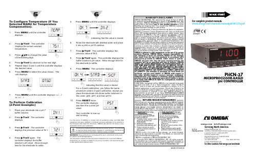
It is the policy of OMEGA worldwide safety and EMC/EMI regulations that apply. OMEGA is constantly pursuing certification of its products to OMEGA will add the CE mark to These products are not designed for use in, and should not be used The information contained in this document is believed to be correct but OMEGA Engineering, Inc. accepts no liability for any errors it contains, and reserves the right This device is marked with the international caution symbol. It is important to read the Setup Guide before installing or commissioning this device as it contains important information relating to safety and EMC.until the controller displays.For complete product manual:/manuals/manualpdf/M1MENU until thePress ᮣT/mV to display r.2 =f or r.2 =c(temperature unit of F or C).Press ᮡ/pH to select the desired temperature unit.Press MENU to select the calibration. The unit displays.Proceed with Calibration depending on Temperature Compensation Setting:If you choose OFF, go to “To Perform Calibration” section.Connect the pH Electrode1.Secure the pH electrode to the pH input BNC connector on the back of the controller.2.If you are using automatic temperature compensation (ATC), connect the RTD as shown below.apply Power1.Apply ac power to the unit.The unit initializes, flashing the following messages: rst , ph , init . Then a pH value appears.2.Verify that a value appears. If not:•Remove ac power.•Verify the TB1 power connections.•Check your power source.•Apply ac power again.234Using This Quick Start Manua lUse this Quick Start manual to set up your pHController and begin operation. Information is provided on how to:•Mount the controller •Connect ac Power•Connect a pH electrode•Calibrate the controller prior to useFor complete information on this controller, refer to the Operator’s Manual.Before You BeginIn addition to the meter and the related parts, you will need the following items to set up your meter:•ac power, as listed on meter’s ID/Power Label •pH electrode (with BNC input connector)•1⁄8” flat blade screwdriverMount the Unit1.Cut a panel opening using the dimen s ions shown to the right.2.Position the unit in the open i ng, making sure the front bezel gasket is flush to the panel.3.Slide on mounting bracket to secure.Connect ~ac PowerWarning: Do not connect AC power to your device until you have completed all input and output connections. This device must only be installed by a specially trained electrician with corresponding qualifications. Failure to follow all instructions and warnings may result in injury!1.Remove the panel at the back of the unit.2.Locate the TB1 connector.3.Insert the correct wire in each terminal as shown in the following figure and tighten the lockdown screws.4.Tug gently on the wires to verify the connections.MANU = the controller uses a manually entered value for temperature compensation.METR = the controller uses the RTD input for automatic temperature compensation.to select the temperaturecompensation setting shown. The controller To Set The Decimal Point Position:If it’s not already shown, press MENU until the controller displays Press ᮣT/mV . The controller displays:to move the decimal point to the desired location. The choices are ff.ff , fff.f , orffff .。
Omega 产品说明书:Style 1、Style 1-B、Style 2 和 Style 3 的

CO1, CO2, CO3“Cement-On” Thermocoup lesUser’s Guidee-mail:**************For latest product manuals:https:///en-us/pdf-manualsShop online at ***********************Servicing North America:Omega Engineering, Inc.Toll-Free: 1-800-826-6342 (USA & Canada only) Customer Service: 1-S00-622-2378 (USA & Canada only)Engineering Service: 1-800-872-9436 (USA & Canada only) Tel: (203) 359-1660 Fax: (203) 359-7700 e-mail:**************For Other Locations Visit /worldwideU.S.A.Headquarters:Section 1 General DescriptionStyle 1 & Style 1-B "Cement-On" ermocouples are made from 0.005 in thermocouple embedded between two layers of high tempreture polymer / glass laminate. is laminate generally limits the maximum temperature for construction to 260° (500°F) continuous, 370°C (698°F) for short duration. e insulated lead wire is silicone impreg-nated glass braid. e sislicone impregration provides abrasion resis-tance, but is destroyed at approximately 205°(400° F). e glass braid provides electrical insulation to 480°C (896°F).Style 1-B "Cement On" e thin sensor (0.008") is embedded between two thin, high-temperature polymer laminates which both support and electrically insulate the foil section as well as provide a at surface for cementing. e polymer laminate, in general, determines the maxi-mum temperature of the construction which is 260°C (500°F) continu-ous and up to 370°C (698°F) for short duration. Each Style 1 unit includes 1m (40")of glass braid insulated 30 gauge thermocouple wire which is bonded to the foil and strain relieved by laminate. An applica-tion instruction sheet accompanies each packaged Cement-On type thermocouples.Style II "Cement-On" sensors are made from .0005 "foil with .002" leads. e foil leads are fastened to a polyimide lm frame which is a tough, exible, dimensionally stable material rated for 260°C (500°F) continuous service.Style III "Cement-On's" are made from 30 gauge (0.010") diameter thermocouple wire. e thermocouple is bead welded and embedded between two layers Of paper thin polyimide lm. is lm is rated up to 370°C (698°F). e insulated lead Wire is silicone impregnated glass braid With the same qualities listed above for Style I. e table on the following page lists the maximum temperature for the three styles of thermocouples."Cement-OR" ermocouples can be bonded to most surfaces using OB Epoxy Adhesives 100, 101, and 200. Each epoxy has di erent temperature ratings, cure characteristics, and thermal conductivity factors. Refer to the Omega Temperature Measurement Handbook for more information on OB Epoxies. When using epoxies, be sure that the surfaces to be bonded are clean. Use an appropriate solvent or detergent for cleaning.For temperatures above 5CO°F, use Omega CC High Temperature Cement to bond Style II "Cement-On" ermocouples to most metals and ceramics. CC Cement is not recommended for Style I and Style III "Cement-OR's". For applications under 26°C (500°F), use OB 200 Epoxy.OB 200 is a specially formulated epoxy with high thermal conductiv-ity. To retain the fast speed of response, use a thin layer of adhesive.Section 2 Installation2.1 Using Adhesives1.2.3.4.5.Style I: Use a clamp to strain relief the lead wire downstream from the sensor2.2 Installation Tips1.2.3.4.5.Style IStyle I-BStyle IIDuring application, the foil thermocouple can either be peeled from the frame or released by applying heat. e .002" foil leads are uninsulated. Before working on electrically conductive surfaces, lay down a thin layer of insulating Omega CC Cement or OB Epoxy and let it dry. is ensures that the leads are fully insulated from the surface. en apply a thin layer of the cement or epoxy to the surface, and brush the leads into it (use this step alone for non-conductive surfaces). Bond insulated thermocouple lead wire to the foil leads by silver soldering or resistance welding. Use thirty gauge insulated ther-mocouple lead wire such as GG- (K or E or T)-30. Refer to the Omega Temperature Measurement Handbook for information on thermocouple wire. Install Type T (Copper/Constantan) foil junction by carefully pressing into a owed thin layer Of so solder. Type K (Chromega® / Alomega™) and Type E (Chromega®/Con-stantan) will not bond properly with so solder. However, with care and skill, a bond can be made using a low temperature silver solder of less than IO00°F.Style III : ese "Cement-On" lhermocouples may be bonded to mostsurfaces using the same technique as for Style LWARRANTY /DISCLAIMEROMEGA ENGINEERING, INC. warrants this unit to be free of defects in materials and workmanship for a period of 13 months from date of purchase. OMEGA’s WARRANTY adds an additional one (1) month grace period to the normal one (1) year product warranty to cover handling and shipping time. This ensures that OMEGA’s customers receive maximum coverage on each product.If the unit malfunctions, it must be returned to the factory for evaluation. OMEGA’s Customer Service Department will issue an Authorized Return (AR) number immediately upon phone or written request. Upon examination by OMEGA, if the unit is found to be defective, it will be repaired or replaced at no charge. OMEGA’s WARRANTY does not apply to defects resulting from any action of the purchaser, including but not limited to mishandling, improper interfacing, operation outside of design limits, improper repair, or unauthorized modi cation. This WARRANTY is VOID if the unit shows evidence of having been tampered with or shows evidence of having been damaged as a result of excessive corrosion; or current, heat, moistureor vibration; improper speci cation; misapplication; misuse or other operating conditions outside of OMEGA’s control. Components in which wear is not warranted, include but are not limited to contact points, fuses, and triacs.OMEGA is pleased to o er suggestions on the use of its various products. However, OMEGA n either assumes r esponsibility for any omissions or e rrors nor assumes liability for any damages that result from the use of its products in accordance with information provided by OMEGA, either verbal or written. OMEGA warrants only that the parts manufactured by the company will be as speci ed and free of defects. OMEGA MAKES NO OTHER WARRANTIES OR REPRESENTATIONS OF ANY KIND WHATSOEVER, EXPRESSED OR IMPLIED, EXCEPT THAT OF TITLE, AND ALL IMPLIED WARRANTIES INCLUDING ANY WARRANTY OF MERCHANTABILITY AND FITNESS FOR A PARTICULAR PURPOSE ARE HEREBY DISCLAIMED. LIMITATION OF LIABILITY: The remedies of purchaser set forth herein are exclusive, and the total liability of OMEGA with respect to this order, whether based on contract, warranty, negligence, indemni cation, strict liability or otherwise, shall not exceed the purchase price of the component upon which liability is based. In no event shall OMEGA be liable for consequential, incidental or special damages.CONDITIONS: Equipment sold by OMEGA is not intended to be used, nor shall it be used: (1) as a “Basic Component” under 10 CFR 21 (NRC), used in or with any nuclear installation or activity; or (2) in medical applications or used on humans. Should any Product(s) be used in or with any nuclear installation or activity, medical application, used on humans, or misused in any way, OMEGA assumes no responsibility as set forth in our basic WARRANT Y / DISCLAIMER language, and, additionally, purchaser will indemnify OMEGA and hold OMEGA harmless from any liability or damage whatsoever arising out of the use of the Product(s) in such a manner.RETURN REQUESTS/INQUIRIESDirect all warranty and repair requests/inquiries to the OMEGA Customer Service Department. BEFORE RETURNING A NY PRODUCT(S) TO OMEGA, P URCHASER MUST OBTAIN AN AUTHORIZED RETURN (AR) NUMBER FROM OMEGA’S CUSTOMER SERVICE DEPARTMENT (IN ORDER TO AVOID PROCESSING DELAYS). The assigned AR number should then be marked on the outside of the return package and on any correspondence.The purchaser is responsible for shipping charges, freight, insurance and proper packaging toprevent breakage in transit.O MEGA’s policy is to make running changes, not model changes, whenever an improvement is possible. This a ords our customers the latest in technology and engineering.OMEGA is a trademark of OMEGA ENGINEERING, INC.© Copyright 2019 OMEGA ENGINEERING, INC. All rights reserved. This document may not be copied, photocopied, reproduced, translated, or reduced to any electronic medium or machine-readable form, in whole or in part, without the prior written consent of OMEGA ENGINEERING, INC.FOR WARRANT Y RETURNS, please havethe following information available BEFORE contacting OMEGA:1. Purchase Order number under which the product was PURCHASED,2. M odel and serial number of the product under warranty, and3. R epair instructions and/or speci c problems relative to the product.FOR NON-WARRANTY REPAIRS, consult OMEGA for current repair charges. Have the following information available BEFORE contacting OMEGA:1. P urchase Order number to cover the COST of the repair,2. Model and serial number of the product, and3. Repair instructions and/or speci c problems relative to the product.Where Do I Find Everything I Need for Process Measurement and Control?OMEGA…Of Course!Shop online at TEMPERATUREermocouple, RTD & ermistor Probes,Connectors, Panels & Assemblies Wire: ermocouple, RTD & ermistor Calibrators & Ice Point References Recorders, Controllers & Process MonitorsInfrared PyrometersDATA ACQUISITIONCommunications-Based Acquisition SystemsWireless Sensors, Transmitters,& ReceiversData Logging Systems Signal ConditionersData Acquisition So wareRotameters, Gas Mass Flowmeters & Flow Computers Air Velocity IndicatorsTurbine/Paddlewheel SystemsTotalizers & Batch ControllersPRESSURE, STRAIN AND FORCETransducers & Strain Gages Displacement Transducers Load Cells & Pressure GagesInstrumentation & AccessoriesHEATERSFLOW/LEVELMetering & Control InstrumentationRefractometersPumps & TubingAir, Soil & Water Monitors Industrial Water & WastewaterTreatmentpH, Conductivity & DissolvedOxygen InstrumentsENVIRONMENTAL MONITORING ANDpH Electrodes, Testers & Accessories Benchtop/Laboratory Meters Controllers, Calibrators, Simulators& PumpsIndustrial pH & Conductivity EquipmentpH/CONDUCTIVITYHeating CableImmersion & Band Heaters Cartridge & Strip HeatersFlexible HeatersLaboratory Heaters。
Omega RCK Series产品说明书

e-mail:**************For latest product manuals:ROCKERSShop online atUser’s GuideRCK SeriesServicing North America:U.S.A.:Omega Engineering, Inc., One Omega Drive, P.O. Box 4047ISO 9001 Certified Stamford, CT 06907-0047 USAToll Free: 1-800-826-6342TEL: (203) 359-1660FAX: (203) 359-7700e-mail:**************Canada:976 BergarLaval (Quebec), Canada H7L 5A1Toll-Free: 1-800-826-6342TEL: (514) 856-6928FAX: (514) 856-6886e-mail:*************For immediate technical or application assistance:U.S.A. and Canada:Sales Service: 1-800-826-6342/1-800-TC-OMEGA ®Customer Service: 1-800-622-2378/1-800-622-BEST ®Engineering Service: 1-800-872-9436/1-800-USA-WHEN ®Mexico:En Español: 001 (203) 359-7803FAX: (001) 203-359-7807**************.mx e-mail:*****************Servicing Europe:Benelux :Managed by the United Kingdom Office Toll-Free: 0800 099 3344TEL: +31 20 347 21 21FAX: +31 20 643 46 43e-mail:**************Czech Republic:Frystatska 184733 01 Karviná, Czech Republic Toll-Free: 0800-1-66342TEL: +420-59-6311899FAX: +420-59-6311114e-mail:*****************France:Managed by the United Kingdom OfficeToll-Free: 0800 466 342TEL: +33 (0) 161 37 29 00FAX: +33 (0) 130 57 54 27e-mail:**************Germany/Austria:Daimlerstrasse 26D-75392 Deckenpfronn, Germany Toll-Free************TEL: +49 (0) 7059 9398-0FAX: +49 (0) 7056 9398-29e-mail:*************United Kingdom:OMEGA Engineering Ltd.ISO 9001 Certified One Omega Drive, River Bend Technology Centre, NorthbankIrlam, Manchester M44 5BD England Toll-Free: 0800-488-488TEL: +44 (0)161 777-6611FAX: +44 (0)161 777-6622e-mail:**************.ukOMEGAnet ®Online Service Internet e-mail **************It is the policy of OMEGA Engineering, Inc. to comply with all worldwide safety and EMC/EMI regulations that apply. OMEGA is constantly pursuing certification of its products to the European New Approach Directives. OMEGA will add the CE mark to every appropriate device upon certification.The information contained in this document is believed to be correct, but OMEGA accepts no liability for any errors it contains, and reserves the right to alter specifications without notice.WARNING: These products are not designed for use in, and should not be used for, human applications.BEFORE USE:Please read the following instructions:Read the Manual first before operating the instrumentFor indoor use onlyAmbient temperature range +5°C to +40°CUse in a well-ventilated area.Relative humidity not exceeding 80%Mains supply fluctuation not exceeding 10%WarningALL UNITS MUST BE GROUNDEDCheck the line supply is sufficient to meet the power requirement of the unit!OverviewRockers – The platform on the mixers move in non‐horizontal direction as the motor rotated, i.e. the rocking movement. There are two types of rockers provided: 1, the gyration type and the wave type. With tilted angle in one end, the gyration mixers gyrate in three‐dimension. This mixing action is suitable for full flashing some floated object by liquid, such as staining and de‐staining gels and low foaming mixing purpose. The wave type is based on see‐saw action to create wave‐like mixing of the liquid and suitable for Petri‐dish and culture fluids.Figure 4: Overview of the mini scale 3D gyrator rocker (RCK‐31). 1 Electrical socket; 2Slip‐proof platform; 3 LED display on Digital front panelFigure 5: Overview of the lab scale see‐saw rocker (RCK‐21). 1 Electrical socket;2 Slip‐proof platform;3 Digital front panelOperationAlways install the carrier or platform before turning on the machine. All platforms or carriers are shipped in pre‐installed status. For safety reason, please check all the locking screw and tighten again if necessary. The locking screws might be loosened during transportation!Place the machines on the flat and steady surface and keep away from other objects for safe operation.Check the electrical safety status and the power switch must be in “OFF” position before plug into the power outlet. The machines come with IEC electrical socket and double fuses for safety operation.For the 3D Gyrator Rockers, adjust the tilted angle before loading the samples. Set the speed to the minimum rpm. And examine the nut underneath the center cylinder shaft turning front, then stop the machines and tilt the platform to desired angle.Figure 13: Overview of head box .Load the samples first before turning on the machine. Be aware of loading sample evenly and never overload the samples.Always start with low speed and gradually adjust the speed, especially for the analog model.There are two different types of control in most of the mixers: digital and analog. Both control modes can adjust the speed and timer of the mixers.1. Digital Control of Speed and TimersFigure 14: Overview of the front panel of the digital control mode. 1 Start/stopbutton; 2 Mode button; 3 Indicator beneath “rpm”; 4 Indicator beneath “time”;5 Digital display;6 Speed controlThere are two buttons and one knob on the digital panel: The knob is the main switch for turning on the machine and adjusting the speed and timer; the mode button has the selection function to either adjust the timer or the speed; the start/stop button is used to start or stop the mixing process. The panel has LED numeric display and red indicators. When starting the mixers, the red indicator between the start/stop and mode buttons illuminate, and when pressing the mode button, the read indicators underneath the rpm and minute alternatively illuminate to show the status of display.1.1 Press the knob to turn on the unit. The LED display the number of last saved rpm and timer setting. And the indicator underneath the rpm illuminate, adjust the rpm by the knob to desired value. And move the illuminated indicator from underneath rpm to minute by pressing the mode button, the display will show the set timer and change to the desired timing value, and finally press the start/stop button to start the machine. If using the knob to turn off the machine, the set timer and speed will automatically be saved, and carry on the next time operation.1.2 Adjust the timer: press mode button until the indicator underneath of min illuminate, turn the knob to desired count‐down minute. To disable the timer, just turn the knob to ‐‐‐, the unit will continuously operate until manually stopping the unit. When the timer reaches to zero, the unit stops and sounds an alert.The default time unit is minute (displayed nnnn), but it can be changed to Hour: Minute (displayed H:nn) or Minute: Second (displayed nn:ss). To do so, turn off the machine completely with the main electrical switch, press the knob and mode button simultaneously, and turn the machine back on. The display will display 88:88 and then off. Turn the machine on using the knob, the display will show nn:ss (for minute: second) or H:nn (for hour : minute) or nn (for minute), and turn the knob to the desired unit and press the knob again to turn off the machine, the display will show OFF. When turning on the machine next time, the newly set unit will take effect.1.3 The speed and timer can be adjusted during operation without stopping the machine. Suggest users to use lower speed to start the machine and adjust the speed to optimum mixing status slowly to avoid the spill or safety problems during the operation.2. Analog Control of Speed and TimersFigure 15: Overview of the front panel of the analog control mode. 1 Timer knob;2 Main switch;3 Speed knobThere are two knobs and one main switch on the front panel of the analog types of the mixers. The main switch has three stages func tion: ON, OFF and Timer. For con ti nuousop erati on, place the switch to the “ON” posi ti on, and turn the rpm knob (on the right hand side) to desired speed. When using ti mer, place the switch to “Timer” posi ti on, and adjust the speed using speed knob. Before turning on the machine, please turn the speed knob all the way to the le ft hand side (minimum level)! And adjust the speed gradually. Maintenance and ServiceThis range of equipment only requires rou ti ne cleaning for the maintenance. Before cleaning, Always unplug the equipment from the electrical outlet. Use so ft cloth with mild detergent to clean the surface of the equipment.WARRANTY/DISCLAIMEROMEGA ENGINEERING, INC. warrants this unit to be free of defects in materials and workmanship for a period of 36 months from date of purchase. OMEGA’s WARRANTY adds an additional one (1) month grace period to normal three (3) year product warranty to cover handling and shipping time. This ensures that OMEGA’s customers receive maximum coverage on each product.If the unit malfunctions, it must be returned to the factory for evaluation. OMEGA’s Customer Service Department will issue an Authorized Return (AR) number immediately upon phone or written request. Upon examination by OMEGA, if the unit is found to be defective, it will be repaired or replaced at no charge. OMEGA’s WARRANTY does not apply to defects resulting from any action of the purchaser, including but not limited to mishandling, improper interfacing, operation outside of design limits, improper repair, or unauthorized modification. This WARRANTY is VOID if the unit shows evidence of having been tampered with or shows evidence of having been damaged as a result of excessive corrosion; or current, heat, moisture or vibration; improper specification; misapplication; misuse or other operating conditions outside of OMEGA’s control. Components in which wear is not warranted, include but are not limited to contact points, fuses, and triacs.OMEGA is pleased to offer suggestions on the use of its various products. However, OMEGA neither assumes responsibility for any omissions or errors nor assumes liability for any damages that result from the use of its products in accordance with information provided by OMEGA, either verbal or written. OMEGA warrants only that the parts manufactured by the company will be as specified and free of defects. OMEGA MAKES NO OTHER WARRANTIES OR REPRESENTATIONS OF ANY KIND WHATSOEVER, EXPRESSED OR IMPLIED, EXCEPT THAT OF TITLE, AND ALL IMPLIED WARRANTIES INCLUDING ANY WARRANTY OF MERCHANTABILITY AND FITNESS FOR A PARTICULAR PURPOSE ARE HEREBY DISCLAIMED. LIMITATION OF LIABILITY: The remedies of purchaser set forth herein are exclusive, and the total liability of OMEGA with respect to this order, whether based on contract, warranty, negligence, indemnification, strict liability or otherwise, shall not exceed the purchase price of the component upon which liability is based. In no event shall OMEGA be liable for consequential, incidental or special damages.CONDITIONS: Equipment sold by OMEGA is not intended to be used, nor shall it be used: (1) as a “Basic Component” under 10 CFR 21 (NRC), used in or with any nuclear installation or activity; or (2) in medical applications or used on humans. Should any Product(s) be used in or with any nuclear installation or activity, medical application, used on humans, or misused in any way, OMEGA assumes no responsibility as set forth in our basic WARRANTY/DISCLAIMER language, and, additionally, purchaser will indemnify OMEGA and hold OMEGA harmless from any liability or damage whatsoever arising out of the use of the Product(s) in such a manner.RETURN REQUESTS/INQUIRIESDirect all warranty and repair requests/inquiries to the OMEGA Customer Service Department. BEFORE RETURNING ANY PRODUCT(S) TO OMEGA, PURCHASER MUST OBTAIN AN AUTHORIZED RETURN (AR) NUMBER FROM OMEGA’S CUSTOMER SERVICE DEPARTMENT (IN ORDER TO AVOID PROCESSING DELAYS). The assigned AR number should then be marked on the outside of the return package and on any correspondence.The purchaser is responsible for shipping charges, freight, insurance and proper packaging to prevent breakage in transit.FOR WARRANTY RETURNS, please have the following information available BEFORE contacting OMEGA:1.Purchase Order number under which the productwas PURCHASED,2.Model and serial number of the product underwarranty, and3.Repair instructions and/or specific problemsrelative to the product.FOR NON-WARRANTY REPAIRS,consult OMEGA for current repair charges. Have the following information available BEFORE contacting OMEGA: 1. Purchase Order number to cover the COSTof the repair,2.Model and serial number of the product, and3.Repair instructions and/or specific problemsrelative to the product.OMEGA’s policy is to make running changes, not model changes, whenever an improvement is possible. This affords our customers the latest in technology and engineering.OMEGA is a registered trademark of OMEGA ENGINEERING, INC.© Copyright 2009 OMEGA ENGINEERING, INC. All rights reserved. This document may not be copied, photocopied,Where Do I Find Everything I Need for Process Measurement and Control?OMEGA…Of Course!Shop online at SMTEMPERATUREThermocouple, RTD & Thermistor Probes, Connectors, Panels & AssembliesWire: Thermocouple, RTD & ThermistorCalibrators & Ice Point ReferencesRecorders, Controllers & Process MonitorsInfrared PyrometersPRESSURE, STRAIN AND FORCETransducers & Strain GagesLoad Cells & Pressure GagesDisplacement TransducersInstrumentation & AccessoriesFLOW/LEVELRotameters, Gas Mass Flowmeters & Flow ComputersAir Velocity IndicatorsTurbine/Paddlewheel SystemsTotalizers & Batch ControllerspH/CONDUCTIVITYpH Electrodes, Testers & AccessoriesBenchtop/Laboratory MetersControllers, Calibrators, Simulators & PumpsIndustrial pH & Conductivity EquipmentDATA ACQUISITIONData Acquisition & Engineering SoftwareCommunications-Based Acquisition SystemsPlug-in Cards for Apple, IBM & CompatiblesDatalogging SystemsRecorders, Printers & PlottersHEATERSHeating CableCartridge & Strip HeatersImmersion & Band HeatersFlexible HeatersLaboratory HeatersENVIRONMENTALMONITORING AND CONTROLMetering & Control InstrumentationRefractometersPumps & TubingAir, Soil & Water MonitorsIndustrial Water & Wastewater TreatmentpH, Conductivity & Dissolved Oxygen Instruments。
Omega M-3637 用户指南说明书

User’s Guidee-mail:**************M -3637USA:ISO 9001 Certified Servicing North America:976 Bergar Laval (Quebec) H7L 5A1Tel: (514) 856-6928FAX: (514) 856-6886e-mail:****************Canada:One Omega Drive,Box 4047 Stamford,CT 06907-0047Tel: (203) 359-1660FAX: (203) 359-7700e-mail:**************Servicing Europe:For immediate technical or application assistance:Postbus 8034, 1180 LA Amstelveen, The NetherlandsT el: (31) 20 64184 Fax (31) 20 6434643T oll Free in Benelux: 06 0993344e-mail:************USA andCanada:Mexico andLatin America:Sales Service: 1-800-826-6342 / 1-800-TC-OMEGASMCustomer Service: 1-800-622-2378 / 1-800-622-BESTSMEngineering Service: 1-800-872-9436 / 1-800-USA-WHENSMT el: (95) 800-TC-OMEGASM FAX: (95) 203-359-7807EnEspanol:(95)203359-7803e-mail:*****************Benelux:Czech Republic: France: Germany/Austria: United Kingdom: ISO 9002 Certified Ostravska 767,733 01 KarvinaT el:42(69)6311899 Fax:42(69) 6311114e-mail:***************9, rue Denis Papin, 78190 TrappesT el: (33) 130-621-40 Fax: (33) 130-699-120T oll Free in France: 0800-4-06342e-mail:****************Daimlerstrasse 26, D-75392 Deckenpfronn, Germany T el: 49 (07056) 301 FAX: 49 (07056) 8540T oll Free in Germany: 0130 11 21 66e-mail:*****************25 Swannington Road, P.O. Box 7, Omega Drive, Broughton Astley, Leicestershire, Irlam, Manchester, LE9 6TU, England M44 5EX, EnglandT el: 44 (1455) 285520 T el: 44 (161) 777-6611 FAX: 44 (1455) 283912 FAX: 44 (161) 777-6622 T oll Free in England: 0800-488-488e-mail:************It is the policy of OMEGA to comply with all worldwide safetyand EMC/EMI regulations that apply. OMEGA is constantlypursuing certification of its products to the European NewApproach Directives. OMEGA will add the CE mark to every appropriate device upon certification. The information contained in this document is believed to be correct but OMEGA Engineering, Inc. accepts no liability for any errors it contains, and reserves the right to alter specifications without notice.WARNING: These products are not designed for use in, andshould not be used for, patient connected applications.DRA-RTT-2Contents1. PROCEDURE TO OPEN THEENCLOSURE2. CALIBRATION INSTRUCTIONS 2.1 Switch Setting2.2 Calibration Tables2.3 Calibration Example3. CONNECTION DIAGRAM4. MECHANICAL DIMENSIONS5. SPECIFICATIONSPROCEDURE TO OPEN THE ENCLOSURE Carefully insert a proper screwdriver tip into the side slot. By pressing inward and rotate the plastic locker will release.Gently pull out the unit's back cover.CALIBRATION INSTRUCTIONS2.1 Switch Setting Six DIP switches are located inside the enclosure for coarse range, and two multi-turn potentiometers are located on the front panel for fine tuning.Define the desired range limits:Tmin - the temperature at which the output current is 4mA.Tmax - the temperature at which the output current is 20mA.Tspan - the difference between Tmax and Tmin.According to the following tables, set switches no.1 to 3 for the Zero (Tmin), and set switches 4 to 6 for the Span (Tspan).Note: "1" represents the switch "ON" state.2.1.*2.2 Calibration Tables"Zero" T ableTmin˚C SW1 SW2 SW3 -55 ~ 25 1 1 1 -25 ~ 7 0 1 1 7 ~ 40 1 0 1 40 ~ 73 0 0 1 73 ~ 105 1 1 0 105 ~ 138 0 1 0 138 ~ 170 1 0 0 170 ~ 202 0 0 0"Span" T ableTspan˚C SW4 SW5 SW6 30 ~ 55 1 1 1 50 ~ 90 1 0 0 90 ~ 185 0 1 0 185 ~ 380 0 0 1 380 ~ 810 0 0 02.3 Calibration Example:Needed: -50 ~ +50˚CTmin: -50˚CTspan: 50-(-50)=100˚C+ -DVM 0-20m A-+POWERSUPPLY24VPt-100 CALIBRATORSet the DIP switches to: 1,1,1,0,1,0(sw1..sw6)Set the calibrator for -50˚ and calibrate "Z" to 4.000mA.Set the calibrator for +50˚ and calibrate "S" to 20.000mA.Repeat steps a~c until satisfactory results are obtain.CONNECTION DIAGRAMb.c.d.3.0a.4. MECHANICAL DIMENSIONSDimensions in mm (inch)RTT-2Pt-10058 (2.28)90 (3.54)17.5 (0.7)5. SPECIFICATIONSINPUT: 3-wire Pt-100 according to BS1904 and DIN 43760 characteristics, a= 0.00385INPUT SPAN CHANGE: 30 to 810˚CSpan Calibration: Three DIP switches and "Span" potentiometerINPUT ZERO CHANGE: -55 to +202˚CZero Calibration: Three DIP switches and "Zero" potentiometerLEADS COMPENSATION ERROR:< ±0.05˚C/ 10 Ω leads resistanceSENSOR LEAD RESISTANCE:< 50Ω (two ways)SENSOR EXCITATION: < 1mAOUTPUT: 4 - 20mA, (28mA limited)LOOP RESISTANCE:Rmax(Ω) = (Vsupply-10)/.02ACCURACY (linearity, hysteresis and repeatability): < ± 0.1% of spanTEST TERMINALS: 40 to 200 mV represent 4-20 mA SUPPLY VOLTAGE: 10 - 36 Vdc reversepolarity protectedSUPPLY AND LOAD V ARIATION EFFECT:< ±0.03% of span for full change TEMPERATURE STABILITY: ±0.015% of span /1˚C OPERATING TEMPERATURE: -4 to 158˚F (-20 to +70˚C) STORAGE TEMPERA TURE: -22 to 185˚F (-40 to +90˚C) HUMIDITY: 5 - 95% relative humidity, non-condensing ENCLOSURE: Plastic polycarbonate PROTECTION LEVEL: enclosure: According to IP-40 T erminals: According to IP-20 MOUNTING: Standard 35 mm DIN rail WEIGHT: 2.5 oz (70 grams)WARRANTY/DISCLAIMEROMEGA ENGINEERING, INC. warrants this unit to be free of defects in materials and workmanship for a period of 13 months from date of purchase. OMEGA Warranty adds an additional one (1) month grace period to the normal one (1) year product warranty to cover handling and shipping time. This ensures that OMEGA’s customers receive maximum coverage on each product. If the unit should malfunction, it must be returned to the factory for evaluation. OMEGA’s Customer Service Department will issue an Authorized Return (AR) number immediately upon phone or written request. Upon examination by OMEGA, if the unit is found to be defective it will be repaired or replaced at no charge. OMEGA’s WARRANTY does not apply to defects resulting from any action of the purchaser, including but not limited to mishandling, improper interfacing, operation outside of design limits, improper repair, or unauthorized modification. This WARRANTY is VOID if the unit shows evidence of having been tampered with or shows evidence of being damaged as a result of excessive corrosion; or current, heat, moisture or vibration; improper specification; misapplication; misuse or other operating conditions outside of OMEGA’s control. Components which wear are not warranted, including but not limited to contact points, fuses, and triacs.OMEGA is pleased to offer suggestions on the use of its various products. However, OMEGA neither assumes responsibility for any omissions or errorsnor assumes liability for any damages that result from the use of its products in accordance with information provided by OMEGA, either verbal or written. OMEGA warrants only that the parts manufactured by it will be as specified and free of defects.OMEGA MAKES NO OTHER WARRANTIES OR REPRESENTATIONS OF ANY KIND WHATSOEVER, EXPRESSED OR IMPLIED, EXCEPT THAT OF TITLE, AND ALL IMPLIED WARRANTIES INCLUDING ANY WARRANTY OF MERCHANTABILITY AND FITNESS FOR A PARTICULAR PURPOSE ARE HEREBY DISCLAIMED. LIMITATION OF LIABILITY: The remedies of purchaser set forth herein are exclusive and the total liability of OMEGA with respect to this order, whether based on contract, warranty, negligence, indemnification, strict liability or otherwise, shall not exceed the purchase price of the component upon which liability is based. In no event shall OMEGA be liable for consequential, incidental or special damages. CONDITIONS: Equipment sold by OMEGA is not intendedto be used, nor shall it be used: (1) as a “Basic Component”under 10 CFR 21 (NRC), used in or with any nuclear installation or activity; or (2) in medical applications or used on humans. Should any Product(s) be used in or with any nuclear installation or activity, medical application, used on humans, or misused in any way, OMEGA assumes no responsibility as set forth in our basic WARRANTY/ DISCLAIMER language, and additionally, purchaserwill indemnify OMEGA and hold OMEGA harmless from any liability or d a m a g e whatsoever arising out of the use of the Product(s) in such a manner.OMEGA’s policy is to make running changes, not model changes,whenever an improvement is possible.This affords our customers the latest in technology and engineering.OMEGA is a registered trademark of OMEGA ENGINEERING,INC.© Copyright 1996 OMEGA ENGINEERING, INC. All rights reserved.This document may not be copied, photocopied, reproduced,translated, or reduced to any electronic medium or machine-readable form, in whole or in part, without prior written consent of OMEGA ENGINEERING, INC.RETURN REQUESTS / INQUIRIESDirect all warranty and repair requests/inquiries to the OMEGA Customer Service Department. BEFORE RETURNING ANY PRODUCT(S)TO OMEGA, PURCHASER MUST OBTAIN AN AUTHORIZED RETURN (AR) NUMBER FROM OMEGA’S CUSTOMER SERVICE DEPARTMENT (IN ORDER TO AVOID PROCESSING DELAYS). The assigned AR number should then be marked on the outside of the return package and on any correspondence. The purchaser is responsible for shipping charges,freight, insurance and proper packaging to prevent breakage in transit.FOR WARRANTY RETURNS,please have the followinginformation available BEFOREcontacting OMEGA:1. P .O. number under which theproduct was PURCHASED,2. Model and serial number of theproduct under warranty, and3. Repair instructions and/or specificproblems relative to the product.FOR NON-WARRANTY REPAIRS,consult OMEGA for current repair charges. Have the following information available BEFORE contacting OMEGA:1. P .O. number to cover the COST of the repair,2. Model and serial number of product, and 3. Repair instructions and/or specific problems relative to the product.TEMPERATURE ߜ Thermocouple, RTD & Thermistor Probes,ߜ Connectors, Panels & Assembliesߜ Wire: Thermocouple, RTD & Thermistor ߜ Calibrators & Ice Point Referencesߜ Recorders, Controllers & Process Monitors ߜ Infrared PyrometersPRESSURE, STRAIN AND FORCEߜ Transducers & Strain Gaugesߜ Load Cells & Pressure Gaugesߜ Displacement Transducersߜ Instrumentation & AccessoriesFLOW/LEVELߜ Rotameters, Gas Mass Flowmeters & Flow Computers ߜ Air Velocity Indicatorsߜ Turbine/Paddlewheel Systemsߜ Totalizers & Batch ControllersWhere Do I Find Everything I Need for Process Measurement and Control?OMEGA…Of Course!PH/CONDUCTIVITYߜ pH Electrodes, Testers & Accessoriesߜ Benchtop/Laboratory Metersߜ Controllers, Calibrators, Simulators & Pumpsߜ Industrial pH & Conductivity Equipmentߜ Data Acquisition & Engineering Softwareߜ Communications-Based Acquisition Systemsߜ Plug-in Cards for Apple, IBM & Compatiblesߜ Datalogging Systemsߜ Recorders, Printers & PlottersHEATERSߜ Heating Cableߜ Cartridge & Strip Heatersߜ Immersion & Band Heatersߜ Flexible Heatersߜ Laboratory HeatersENVIRONMENTALMONITORING AND CONTROLߜ Metering & Control Instrumentationߜ Refractometersߜ Pumps & Tubingߜ Air, Soil & Water Monitorsߜ Industrial Water & Wastewater Treatmentߜ pH, Conductivity & Dissolved Oxygen Instruments。
Omega 产品说明书.pdf_1718700255.5672326

e-mail:**************For latest product manuals:User’s GuideIt is the policy of OMEGA Engineering, Inc. to comply with all worldwide safety and EMC/EMI regulations that apply. OMEGA is constantly pursuing certification of its products to the European New Approach Directives. OMEGA will add the CE mark to every appropriate device upon certification.The information contained in this document is believed to be correct, but OMEGA accepts no liability for any errors it contains, and reserves the right to alter specifications without notice.WARNING: These products are not designed for use in, and should not be used for, human applications.Table of contents Page1.Function (1)2.Safety instructions (2)3.Important notes and requirements to installation and operation (3)4.Installation in piping (3)5.Electrical connection (3)5.1.Turbine flow sensor with pulse output (3)6.Cleaning (4)7.Shut-down and disposal (5)8.Materials table (5)9.Technical data (5)10.Dimensions (6)1. FunctionThe turbine flow sensor of the series FTB 370 is atransducer for volume flow recognition or for fluid dosinguse. It has an almost unlimited application through itsexceptionally compact design, its very wide measurementrange and its convincing measurement accuracy.The liquid flowing into the meter is divided by the guidingblades in four split beams. These hit the rotor from fourdirections and put it in motion. The uniform loading ofbearing from four sides causes the forces to cancelthemselves out for the most part and wear is reduced to aminimum.The extremely hard bearing materials, sapphire and hardmetal, ensure in addition an extraordinary life expectancy.The rotor speed is transmitted to an electrical pulse signal(frequency):- The FTB 371 is equipped with rotors which are fittedwith magnets. A Hall effect sensor recognizes therotation of the rotor.In this case, a frequency signal proportional to flow (squarewave) is available.Safety instructions2. Safety instructions•Before you install the product, please read the relevant chapters of the installation instruction carefully. •The turbine flow sensor is only suitable for measurement of fluids – never use the instrument for gas measurements.•Check before installation, whether the material of the turbine flow sensor is suitable for the medium to be monitored (see Materials Table, Chapter 7)!•You can fit the turbine flow control instrument in any position. If it is installed into vertical pipes, the flow direction is preferably upwards. You must avoid a free outlet.•The arrow which is placed on the flow sensor (Î) shows the only permitted flow direction.•For precise measurement, the length of the in - and outlet tubes must be observed(see Chap. 3: Requirements to Installation and Operation).•The internal diameter of the in- and outlet tube must correspond with the internal diameter of the flow sensor. •The flow medium to be monitored should preferably contain as few solid particles as possible. Present particles must not exceed a diameter of 0.02 inch. If necessary, install a filter!•Avoid absolutely the formation of gas bubbles or cavitation in the medium by taking proper measures.•The material of the series FTB 371 is not suitable for monitoring oils. The strength of the used plastic parts would be considerably reduced.•In order to clean the flow sensor of contaminations, flush the unit with water in opposite direction to the flow (see Chap. 7).• A possible blowing out of the instrument must take place only in opposite direction to the flow.•We recommend to use only shielded connection cables. Connect the shield on one side (the wire ends) on ground.•Attention:The upper union nut of the instrument is sealed and must not be opened. When you loosen the union nut, the fixation of the turbine system is disturbed and it will be damaged.•There are special customer designs that may differ from the standard data listed in these instructions – always consider the specifications noted on the type plate.If you should have any problems or questions, please contact your local supplier or directly:Important notes and requirements to installation and operation3. Important notes and requirements to installation and operationObserve the following instructions in order to achieve highest-possible measurement accuracy and specifiedoutput signal.• Before installing the turbine flow sensor flush the pipe carefully. You avoid a blocking of the turbine caused byparticles from the pipe installation.•The installation position of the flow control instruments is unreserved. If it is installed into vertical pipes, the flow direction is preferably upwards. You must avoid a free outlet. •The arrow which is placed on the flow sensor (Î) shows the only permitted flow direction. • A straight tube in front of the flow sensor must be retained, min 10 x ID, i.e. 5,91 inch. Behind the flow sensor,a straight outlet tube of 5 x ID, i.e. 2.95 inch, must be kept. The internal diameter of the in- and outlet tubesmust correspond with the internal diameter of the flow control instrument = 0.591 inch. Before and behind thestabilization tubes, the line may be contracted or enlarged.In practice these instructions often can not be observed. Then the pulse rate and the measurement accuracycan be affected.• The flow medium to be monitored should preferably contain as few solid particles as possible.Present particles must not exceed a diameter of 0.02 inch. If necessary, install a filter!• The materials of the series FTB 370 are not suitable for monitoring oils. The strength of the used plastic partswould be considerably reduced.•Attention:The upper union nut of the instrument is sealed and must not be opened. When you loosen the union nut, thefixation of the turbine system is disturbed and it will be damaged. 4. Installation in piping• Now you can install the t urb i n e in the pipingsystem which was prepared according to chapter3.• The pipe section has a ¾'' NPT thread connectionmale.•Make sure that the correspondent part has a¾'' NPT thread connection female. Notice: • Counterhold! When tightening the correspondent part use only the wrench flat (a / f 1.06'') of the turbine.• If you seal the male thread, take care that nofibrous sealing compounds get into the turbine(hemp or Teflon strip). 5. Electrical connectionAttention: We recommend to use only screened cables. Connect the shield on one side (the wire ends) onground.Electrical connection with 4-pin-plug M12x1Screw on 4-pin-plug M12x1 to sleeve and tighten plug with a starting torque of max. 0.74 ft lb.5.1. Turbine flow sensor with pulse outputThe output signal of Turbotron is a flow-proportional frequency signal. The shape of the signal is a square waveand its amplitude corresponds approximately with the supply voltage. It is an open collector signal, NPN-switching. The connected electronic instrument should have a loading resistance (pull-up or pull-down resistor) of5 k Ω in the inlet.Schematic representationof the plug can be taken from the sketch on the type plate.a / f 1.06CleaningFTB 371 connecting cable6. Cleaning•To remove dirt from the flow sensor, you should flush it with water always in opposite direction to the flow. • Attention:The union nut of the instrument is sealed and must not be opened. When you loosen the union nut, thefixation of the turbine system is disturbed and it will be damaged. A repair in the factory becomes necessary!Cleaning• Warning:A possible blowing-out the instrument with compressed air must only be carried out in opposite direction to theflow.Shut-down and disposal7. Shut-down and disposal•Remove all electrical connections and dismantle the flow sensor.•The turbine unit is made of different materials (see technical data). Don't dispose the turbine unit together with household waste. The official rules of your area have to be observed at disposing of the turbine unit.8. Materials tableMaterialsType FTB 371Pipe section Brass, CuZn36Pb2AsTurbine system PEI UltemRotor assembly Hard ferrite magnetBearing system / shaft shaft Arcap AP1D with hard metal pins in sapphire bearingUnion nut PA GF 30Sensor housing PPO Noryl GFN3O-ring NBRIntegrated temperature sensor (option) Brass or stainless steel 316 SSStrainer (option) POM / stainless steel9. Technical dataThere are special customer designs that may differ from the standard data listed in these instructions – alwaysconsider the specifications noted on the type plate.Turbine flow sensor with pulse outputType FTB 371Material, pipe section BrassNominal diameter ½''Measurement range 0.52 … 10.4 GPMwith special “bearings for low flow rates” (order code 40) with continous flow max.5.2 GPMAccuracy +/-1 % of rangeReproducibility +/-0.2%Start of output signal < 0.08 GPMSensor Hallsensor Output signal- Pulse rate / K-factor - Resolution- Signal shape- Signal current3237 pulses / gal 3.16 fl.dr. / pulse Square wave signal NPN open collector max. 10 mAPull-up-resistance 5kΩ (recommendation)Supply voltage 4.5...24 V DCElectrical connection 5 ft PVC cable, screened(Tmax = 158 °F)or4-pin-plug M12x1Protection class IP 54Max. medium temperature 185 °FNominal pressure 145 psiMax. particle size in the medium < 0.02''Process connection ¾“ NPT maleThe stated values refer to operation with water at 68 °F. Monitoring of fluids with higher viscosities is possible with the effect of deviations from mentioned values.Dimensions10. DimensionsWARRANTY/DISCLAIMEROMEGA ENGINEERING, INC. warrants this unit to be free of defects in materials and workmanship for a period of 13 months from date of purchase. OMEGA’s WARRANTY adds an additional one (1) month grace period to the normal one (1) year product warranty to cover handling and shipping time. T his ensures that OMEGA’s customers receive maximum coverage on each product.If the unit malfunctions, it must be returned to the factory for evaluation. OMEGA’s Customer Service Department will issue an Authorized Return (AR) number immediately upon phone or written request. Upon examination by OMEGA, if the unit is found to be defective, it will be repaired or replaced at no charge. OMEGA’s WARRANTY does not apply to defects resulting from any action of the purchaser, including but not limited to mishandling, improper interfacing, operation outside of design limits, improper repair, or unauthorized modification. This WARRANTY is VOID if the unit shows evidence of having been tampered with or shows evidence of having been damaged as a result of excessive corrosion; or current, heat, moisture or vibration; improper specification; misapplication; misuse or other operating conditions outside of OMEGA’s control. Components in which wear is not warranted, include but are not limited to contact points, fuses, and triacs.OMEGA is pleased to offer suggestions on the use of its various products. However, OMEGA neither assumes responsibility for any omissions or errors nor assumes liability for any damages that result from the use of its products in accordance with information provided by OMEGA, either verbal or written. OMEGA warrants only that the parts manufactured by the company will be as specified and free of defects. OMEGA MAKES NO OTHER WARRANTIES OR REPRESENTATIONS OF ANY KIND W HATSOEVER, EXPRESSED OR IMPLIED, EXCEPT THAT OF TITLE, AND ALL IMPLIED W ARRANTIES INCLUDING ANY W ARRANTY OF MERCHANTABILITY AND FITNESS FOR A PARTICULAR PURPOSE ARE HEREBY DISCLAIMED. LIMITATION OF LIABILITY: The remedies of purchaser set forth herein are exclusive, and the total liability of OMEGA with respect to this order, whether based on contract, warranty, negligence, indemnification, strict liability or otherwise, shall not exceed the purchase price of the component upon which liability is based. In no event shall OMEGA be liable for consequential, incidental or special damages.CONDITIONS: Equipment sold by OMEGA is not intended to be used, nor shall it be used: (1) as a “Basic Component” under 10 CFR 21 (NRC), used in or with any nuclear installation or activity; or (2) in medical applications or used on humans. Should any Product(s) be used in or with any nuclear installation or activity, medical application, used on humans, or misused in any way, OMEGA assumes no responsibility as set forth in our basic WARRANTY/DISCLAIMER language, and, additionally, purchaser will indemnify OMEGA and hold OMEGA harmless from any liability or damage whatsoever arising out of the use of the Product(s) in such a manner.RETURN REQUESTS/INQUIRIESDirect all warranty and repair requests/inquiries to the OMEGA Customer Service Department. BEFORE RET URNING ANY PRODUCT(S) T O OMEGA, PURCHASER MUST OBT AIN AN AUT HORIZED RET URN (AR) NUMBER FROM OMEGA’S CUST OMER SERVICE DEPART MENT (IN ORDER T O AVOID PROCESSING DELAYS). T he assigned AR number should then be marked on the outside of the return package and on any correspondence.The purchaser is responsible for shipping charges, freight, insurance and proper packaging to prevent breakage in transit.FOR WARRANTY RETURNS, please have the following information available BEFORE contacting OMEGA:1.Purchase Order number under whichthe product was PURCHASED,2.Model and serial number of the productunder warranty, and3.Repair instructions and/or specificproblems relative to the product.FOR NON-WARRANTY REPAIRS,consult OMEGA for current repair charges. Have the following information available BEFORE contacting OMEGA:1. Purchase Order number to cover theCOST of the repair,2.Model and serial number of theproduct, and3.Repair instructions and/or specific problemsrelative to the product.OMEGA’s policy is to make running changes, not model changes, whenever an improvement is possible. This affords our customers the latest in technology and engineering.OMEGA is a registered trademark of OMEGA ENGINEERING, INC.© Copyright 2007 OMEGA ENGINEERING, INC. All rights reserved. This document may not be copied, photocopied, reproduced, translated, or reduced to any electronic medium or machine-readable form, in whole or in part, without the prior written consent of OMEGA ENGINEERING, INC.Where Do I Find Everything I Need for Process Measurement and Control?OMEGA…Of Course!Shop online at TEMPERATUREⅪߜThermocouple, RTD & Thermistor Probes, Connectors, Panels & AssembliesⅪߜWire: Thermocouple, RTD & ThermistorⅪߜCalibrators & Ice Point ReferencesⅪߜRecorders, Controllers & Process MonitorsⅪߜInfrared PyrometersPRESSURE, STRAIN AND FORCEⅪߜTransducers & Strain GagesⅪߜLoad Cells & Pressure GagesⅪߜDisplacement TransducersⅪߜInstrumentation & AccessoriesFLOW/LEVELⅪߜRotameters, Gas Mass Flowmeters & Flow ComputersⅪߜAir Velocity IndicatorsⅪߜTurbine/Paddlewheel SystemsⅪߜTotalizers & Batch ControllerspH/CONDUCTIVITYⅪߜpH Electrodes, Testers & AccessoriesⅪߜBenchtop/Laboratory MetersⅪߜControllers, Calibrators, Simulators & PumpsⅪߜIndustrial pH & Conductivity EquipmentDATA ACQUISITIONⅪߜData Acquisition & Engineering SoftwareⅪߜCommunications-Based Acquisition SystemsⅪߜPlug-in Cards for Apple, IBM & CompatiblesⅪߜDatalogging SystemsⅪߜRecorders, Printers & PlottersHEATERSⅪߜHeating CableⅪߜCartridge & Strip HeatersⅪߜImmersion & Band HeatersⅪߜFlexible HeatersⅪߜLaboratory HeatersENVIRONMENTALMONITORING AND CONTROLⅪߜMetering & Control InstrumentationⅪߜRefractometersⅪߜPumps & TubingⅪߜAir, Soil & Water MonitorsⅪߜIndustrial Water & Wastewater TreatmentⅪߜpH, Conductivity & Dissolved Oxygen Instruments M0000/0007。
欧米茄手表三针全自动机械表的调时方法-深圳欧米茄维修中心

近年来,欧米茄更将机芯提升为高抗磁的至臻天文台机芯,并宣布取得与瑞士联邦计量研究院(METAS)合作的全新至臻天文台认证(METAS)。
抛弃繁杂的设计,简约主义如今被更多的年轻人所接受,腕表也如是。
简约的腕表佩戴百搭日常,不管是小礼服,职业装还是日常装扮,都能妥妥撑住。
它所表现出来的优雅大方,始终是无法复制的。
欧米茄星座系列以著名的托爪(Griffes)及瞩目的表盘,展现隽永恒久的迷人设计概念。
27毫米精钢表身配备带有同色调罗马数字的表圈,呈现优雅的复古风情。
白色珠光珍珠母贝表盘镶嵌10枚钻石小时刻度,6点位置设有日历窗口,9点位置亦设有小秒针。
腕表虽然只配备基础功能,但是表盘干净简单,十分符合女性温婉优雅的气质。
这款腕表搭配带有磨砂链节和抛光链杆的表链,光泽饱满,和白色的表盘相得映彰,将女性的优雅发挥到极致。
有太多的品牌华丽而有个性,但是欧米茄的腕表凭借着辨识度高且经典,在腕表界顶级品牌中站住了脚。
即使是高品质腕表也需要进行日常的时间调整。
今天小编就来给大家说一说如何调整欧米茄手表的时间。
欧米茄手表三针全自动机械表的调时方法:1.表把拔出二挡,是调整时间的。
2.切忌不要在晚上23:00-凌晨5:00的时间段调整时间及其手表功能,以免损坏欧米茄手表机件。
3.表把在不拔出状态向上旋转是上发条,新欧米茄表或久置的表建议上发条30次左右,这样能给表储备一些动力,以免因活动量不够而引起的停顿或计时不准。
4.表把拔出一挡,是调日期,1-31日,如碰到只有30天的月份,就要手动调过31号即可。
(要注意日历是在晚上的12点调整的,要是日历白天调整就手动把时间旋转12小时即可)欧米茄手表五针全自动机械表的调时方法:一.表把拔出二挡,是调整时间的。
二.欧米茄表右上按钮是调星期的,表盘内的9点钟位置小表盘显示。
三.表右下按钮是调月份的,表盘内的3点钟位置小表盘显示。
四.切忌不要在晚上23:00-凌晨5:00的时间段调整时间及欧米茄手表功能,以免损坏机件。
欧米茄和斯沃琪联名款水星说明书
欧米茄和斯沃琪联名款水星说明书注意:鉴于欧米茄和斯沃琪联名款水星是一个虚构的产品,以下文章将以虚构的方式讨论该产品。
水星,作为太阳系中最接近太阳的行星,一直以来都吸引着人们的注意。
它神秘而迷人的外表,以及无数的未解之谜,使得许多人对水星的探索产生了极大的兴趣。
为了向世界展示水星的独特之处,两家知名的手表品牌欧米茄和斯沃琪推出了一款联名款水星手表,并制作了一份详细的说明书,让人们更好地了解这颗神秘行星。
首先,让我们来了解一下这款联名手表的设计。
这款水星手表采用了欧米茄和斯沃琪的经典元素进行设计,融合了两个品牌的独特风格。
表盘采用了欧米茄一贯的蓝色设计,象征着水星的神秘与深远。
同时,斯沃琪的创新和科技感也融入到了手表的细节之中,使得其更加令人惊艳。
除了设计之外,这款联名手表还具备了许多令人印象深刻的功能。
首先是其耐磁性能,通过内部的磁屏蔽系统,使得手表在强磁场环境下仍能保持准确的走时。
这一点对于水星的环境来说尤为重要,因为水星表面存在较强的磁场影响,能够成功解决这一问题的设计将无疑成为该联名手表的亮点。
其次,该手表还具备出色的防水性能。
水星的表面温度极高,且存在液态金属,因此联名款水星手表需要能够抵挡极高温度和压力的侵袭。
通过使用最先进的材料和工艺,手表的防水性能得到了极大的提升,使得其能在水星的极端环境下依然运转良好。
此外,联名款水星手表还拥有多功能表盘和夜光指针等实用的设计。
这些功能不仅增加了手表的实用性,也为探索水星提供了便利。
无论是在极光灿烂的夜晚,还是在水星的黑暗深处,手表都能提供准确而清晰的时间显示,帮助人们更好地探索和了解这个神秘行星。
除了手表本身的设计和功能之外,说明书也起到了非常重要的作用。
这份详细的说明书包含了有关水星的各种知识和研究成果,让人们能够更全面地了解这颗神秘行星。
从水星的形成与特征,到其独特的地质构造和大气层,说明书将把人们引入一个充满奇妙和科学的世界。
了解水星作为太阳系中的一颗行星,并向世界展示其独特之处,是欧米茄和斯沃琪联名款水星手表的初衷。