SAES-J-001 Instrumentation Index
强生产品集

ENERGY p.04ACCESS p.14STAPLING p.28LIGATION p.50ENDO DEVICESp.56GASTRIC BAND p.66ORDERING p.72INDEX p.74TABLE OF CONTENTSLinear Cutter 55mm & 75mmSecureStrap™*HARMONIC ACE® 45EHARMONIC SYNERGY® SNGHK2Curved Intraluminal StaplerEchelon Flex™ 45mm & 60mm ENDOPATH® StaplersHARMONIC FOCUS® LongSSL Access SystemENSEAL® T echnology Ligamax ™ 5ENERGYEES ENSEAL ®EES ENSEAL ®ENSEAL ® TRIOCODE TIP SHAFT DIAMETER SHAFT LENGTH QUANTITYENSEAL ® Generator CODE QUANTITY VERSIONMaximizing seal strength. Minimizing thermal tissue damage. • • Seals vessels ≤7 times systolic pressure; patented I-BLADE™ jaw offers strong, • • One-step actuation for both cutting and sealing.Temperature-controlled Tissue-sealingMaximizing seal strength. Minimizing thermal tissue damage.•Temperature-controlled: Temperature automatically regulated to approximately 100°C;thermal spread confined to approximately 1mm outside jaws.•High-performing:Seals vessels7mm with seal strength up to 7 times systolic pressure; patented I-BLADE™ jaw offers strong, uniform compression along the entire seal line.•Adaptable: Control speed of sealing and cutting based on tissue type.•Efficient:One-step actuation for both cutting and sealing.For more information, contact your WARRANTIES CODE DESCRIPTION QUANTITYFCS9FCS17HARMONIC ACE ®CODE TIP SHAFT DIAMETER SHAFT LENGTH HAND PIECE QUANTITYMinimal thermal tissue damage. Increased efficiency.• Precisely directed ultrasonic (mechanical) energy: a blade vibrating at55,000Hz denatures tissue and transforms it into a sticky coagulum.• Minimal thermal spread: safe near vital structures, minimal smoke or char.• One device to dissect, cut, grasp, spot coagulate and create otomies,increasing procedural efficiency.• Seals and divides vessels ħ 5mm *, as well as lymphatics.For more information, contact your* HARMONIC ACE®, HARMONIC FOCUS®, Curved Shearsonly. HK105 and SYNERGY® Blades ≤ 2mm HARMONIC®.HARMONIC ACE®, HARMONIC FOCUS®, HARMONICWAVE®, and HARMONIC SYNERGY® are trademarks ofEthicon Endo-Surgery, Inc.HARMONIC FOCUS ®CODE TIP SHAFT LENGTH HAND PIECE QUANTITY HARMONIC WAVE ®CODE TIP SHAFT DIAMETER SHAFT LENGTH HAND PIECE QUANTITYSNGCB HC325HDH05SNGHK2SNGHK HARMONIC ® Laparoscopic Blades CODE TIP SHAFT DIAMETER SHAFT LENGTH HAND PIECE QUANTITY HARMONIC ® Coagulating ShearsCODE TIP SHAFT DIAMETER SHAFT LENGTH HAND PIECE QUANTITY * Discontinued December 31st, 2010HARMONIC ® Combination Hook Blade CODE TIP SHAFT DIAMETER SHAFT LENGTH HAND PIECE QUANTITY * Discontinued December 31st, 2010HP054HARMONIC ® Generator CartCODE DESCRIPTION QUANTITYHARMONIC ® Generator 300CODE DESCRIPTION QUANTITYACCESSB5ST B5SP B5LT B5LPB5XT EES AccessEES Access5mm ENDOPATH ® XCEL ™ Bladeless Trocars CODE SLEEVE SHAFT LENGTH QUANTITY5mm ENDOPATH ® XCEL ™ Bladeless Trocar with Handle CODE SLEEVE SHAFT LENGTH QUANTITY8mm ENDOPATH ® XCEL ™ Bladeless Trocar CODE SLEEVE SHAFT LENGTH QUANTITY ®™Performance• Abdominal Wall Retention —The cannula’s integrated thread design • Seal Durability• Low System Drag Force —The housing and seal are designed to insertion/extraction force.1• Bladeless, Optical Tip —Direct visualization eliminates blind entry byFor more information, contact your1 P reclinical and Bench top data on file.B12SRT B11LPHB12XT B12LPH B12LPB11LT B11LP B12LTH B12LT B11LTH B12S B1B1215mm ENDOPATH ® XCEL ™ Bladeless TrocarCODE SLEEVE SHAFT LENGTHQUANTITY12mm ENDOPATH ® XCEL ™ Bladeless TrocarsCODE SLEEVE SHAFT LENGTHQUANTITY12mm ENDOPATH ® XCEL ™ Bladeless Trocars with HandleCODE SLEEVE SHAFT LENGTHQUANTITY11mm ENDOPATH ® XCEL ™ Bladeless TrocarsCODE SLEEVE SHAFT LENGTHQUANTITY11mm ENDOPATH ® XCEL ™ Bladeless Trocars with HandleCODE SLEEVE SHAFT LENGTHQUANTITY11mm ENDOPATH ® XCEL ™ Universal SleeveCODE SLEEVE SHAFT LENGTHQUANTITY12mm ENDOPATH ® XCEL ™ Universal SleeveCODE SLEEVE SHAFT LENGTHQUANTITY5mm ENDOPATH ® XCEL ™ Universal SleevesCODE SLEEVE SHAFT LENGTHQUANTITY5mm ENDOPATH ® XCEL ™ Dilating Tip Trocars CODE SLEEVE SHAFT LENGTHQUANTITY11mm ENDOPATH ® XCEL ™ Dilating Tip TrocarCODE SLEEVE SHAFT LENGTHQUANTITY12mm ENDOPATH ® XCEL ™ Dilating Tip TrocarsCODE SLEEVE SHAFT LENGTHQUANTITY23NBS 355NS23NBL35LNSPN120PN150MINI/MICRO TROCARS2mm/3mm ENDOPATH ® Mini/Micro Trocars Non-opticalCODE SLEEVE SHAFT DIAMETERSHAFT LENGTHQUANTITY5mm ENDOPATH ® Non-shielded TrocarsCODE SLEEVE SHAFT DIAMETERSHAFT LENGTHQUANTITY3mm ENDOPATH ® Mini/Micro TrocarCODEDESCRIPTION SHAFT DIAMETERQUANTITY12mm ENDOPATH ® XCEL ™ Blunt Tip Trocar CODE SHAFT LENGTHQUANTITYENDOPATH ® Insufflation Needle Ultra VeressCODE SHAFT LENGTHQUANTITYNEEDLESENDOPATH ® Insufflation Needles PneumoperitoneumCODE SHAFT LENGTHQUANTITY355NA 355DA 511NA 511DA 35LNA 35LDA 512NA512DAFP007FP015FP020ENDOPATH ® Blunt Tip, Obturator, Housing and Olive PlugCODE SLEEVE SHAFT DIAMETER SHAFT LENGTHQUANTITYENDOPATH ® Bladeless, Obturator and HousingCODE SLEEVE SHAFT DIAMETERSHAFT LENGTHQUANTITYENDOPATH ® Dilating Tip, Obturator and HousingCODE SLEEVE SHAFT DIAMETERSHAFT LENGTHQUANTITY10mm/12mm ENDOPATH ® Rigid Thoracic TrocarCODE SLEEVE SHAFT DIAMETER SHAFT LENGTH QUANTITYFLEXIPATH ® Flexible Thoracic TrocarsCODE OBTURATOR AND SLEEVESHAFT DIAMETERSHAFT LENGTHQUANTITYFLEXIPATH ® Flexible Thoracic Trocar PackCODE DESCRIPTIONQUANTITYFLR01FLR03FLR02355HR 512HR 511HR 355RT 511RT 35LRT 512RTENDOPATH ® DEXTRUS ™ HALS ProductsCODE DESCRIPTIONQUANTITYHAND-ASSISTED LAPAROSCOPY (HALS)ENDOPATH ® DEXTRUS ™ HALS RetractorsCODE DESCRIPTIONABDOMINAL QUANTITYENDOPATH ® Disposable Housing Units CODE SHAFT DIAMETERQUANTITYENDOPATH ® Reusable Cannulas CODE SLEEVE SHAFT DIAMETERSHAFT LENGTHQUANTITYSTAPLINGEchelon Flex ™ 45mm Endocutters Reloads Sold SeparatelyCODE ARTICULATIONSHAFT LENGTHQUANTITYEchelon ™ 45mm ReloadsFor use with all Echelon ™ 45mm Endoscopic Staplers (SC45A, EC45A, EC45AL, SC45, EC45, ECLG45)CODE COLOR ROWS TISSUE TYPE OPEN STAPLECLOSED STAPLEQUANTITYFor more information, contact your* Echelon FLEX™=22.6mm Endo GIA ™=21mm Endo GIA Roticulator™ Stapler is a trademark of Covidien Ltd.CTS45ETS 60mm Reloads For use with ETS Flex 60mm Endoscopic Linear Cutters (LTS60A)CODE COLOR ROWS TISSUE TYPE OPEN STAPLECLOSED STAPLEQUANTITYETS Flex 45mm Endocutters Reloads Sold SeparatelyCODE ARTICULATIONSHAFT LENGTHQUANTITYEchelon Flex ™ 60mm Endocutters Cartridges Sold Separately CODE ARTICULATIONSHAFT LENGTHQUANTITYEchelon ™ 60mm ReloadsFor use with all Echelon ™ 60mm Endoscopic Staplers (SC60A, EC60A, LONG60A, SC60, EC60, LONG60)CODE COLOR ROWS TISSUE TYPE OPEN STAPLECLOSED STAPLEQUANTITYETS Flex 60mm Endocutter Reloads Sold SeparatelyCODE ARTICULATIONSHAFT LENGTHQUANTITY* Discontinued December 31st, 2010* Discontinued December 31st, 2010CTS45NKETS Flex 45mm No-Knife Endocutters Reloads Sold SeparatelyCODE ARTICULATIONSHAFT LENGTHQUANTITYETS 45mm Endocutter Reloads Sold Separately CODE ARTICULATIONSHAFT LENGTHQUANTITYETS 45mm ReloadsFor use with all ETS 45mm Endoscopic Linear Cutters (CTS45, ATS45, LONG45A, CTS45NK, ATS45NK, ETS45)CODE COLOR ROWS TISSUE TYPE OPEN STAPLECLOSED STAPLEQUANTITYEZ 45mm Reloads For use with EZ 45mm Endoscopic Linear Cutters (EZ45B, EZ45G)CODE COLOR ROWS TISSUE TYPE OPEN STAPLECLOSED STAPLEQUANTITYEZ 45mm EndocuttersCODE COLOR ARTICULATIONSHAFT LENGTHRELOAD INCLUDEDQUANTITYTLC55TVC55TCT55ETS 35mm Reloads For use with all ETS 35mm Endoscopic Linear Cutters (ATW35, ATB35, TSW35, TSB35)CODE COLOR ROWS TISSUE TYPEOPEN STAPLECLOSED STAPLEQUANTITY55mm Linear Cutters PROXIMATE® 55mm Linear Cutters with Safety LockoutCODE COLOR TISSUE TYPEOPEN STAPLECLOSED STAPLERELOAD INCLUDED QUANTITY55mm Linear Cutter Reloads For use with all 55mm Linear Cutters (TVC55, TLC55, TCT55)CODE COLOR ROWS TISSUE TYPEOPEN STAPLE CLOSED STAPLEQUANTITY ETS Flex 35mm Endocutters ETS Flex 35mm Articulating Endoscopic Linear CuttersCODE ARTICULATION SHAFT LENGTH RELOAD INCLUDED QUANTITYETS 35mm Straight EndocuttersCODE ARTICULATION SHAFT LENGTH RELOAD INCLUDED QUANTITYTLC75TLC10TCD75TCT10TCT75100mm Linear Cutters PROXIMATE® 100mm Linear Cutters with Safety LockoutCODE COLOR TISSUE TYPE RELOAD INCLUDEDOPEN STAPLECLOSED STAPLEQUANTITYNew 55mm Linear Cutter, Selectable Staple Height Reloads Sold SeparatelyCODE SELECTABLE COLORTISSUE TYPE QUANTITYNew 75mm Linear Cutter, Selectable Staple Height Reloads Sold SeparatelyCODESELECTABLE COLOR TISSUE TYPE QUANTITY75mm Linear Cutter Reloads For use with all 75mm Linear Cutters (TLC75, TCD75, TCT75)CODE COLOR ROWS TISSUE TYPE OPEN STAPLECLOSED STAPLEQUANTITY100mm Linear Cutter Reloads For use with all 100mm Linear Cutters (TLC10, TCT10)CODE COLOR ROWS TISSUE TYPE OPEN STAPLECLOSED STAPLEQUANTITY75mm Linear Cutters PROXIMATE® 75mm Linear Cutters with Safety LockoutCODE COLOR TISSUE TYPE RELOAD INCLUDEDOPEN STAPLECLOSED STAPLEQUANTITYNew 55mm Linear Cutter, Selectable ReloadCODEROWS TISSUE TYPE QUANTITYNew 75mm Linear Cutter, Selectable ReloadCODE ROWS TISSUE TYPE QUANTITYECS25ECS21SDH21CDH25SDH25ECS29CDH29SDH29ECS33CDH33SDH33SDH21ACDH25ASDH25AECS29ACDH29ASDH29ACDH33ASDH33AAEndoscopic Curved Circular Staplers ENDOPATH® ILS Endoscopic Curved Intraluminal Staplers—Detachable HeadCODE LUMEN SHAFT LENGTH HEAD DIAMETEROPEN STAPLE CLOSED STAPLEQUANTITYStraight Circular Staplers PROXIMATE® ILS Straight Intraluminal Staplers—Detachable HeadCODE LUMEN SHAFT LENGTH HEAD DIAMETEROPEN STAPLE CLOSED STAPLEQUANTITYEndoscopic Curved Intraluminal StaplersCODE LUMEN SHAFT LENGTH HEAD DIAMETER QUANTITYStraight Intraluminal StaplersCODE LUMEN SHAFT LENGTH HEAD DIAMETER QUANTITYTX30B TX30GTX 30mm Linear Stapler Reloads For use with (TX30B, TX30G)CODE COLOR TISSUE TYPEOPEN STAPLECLOSED STAPLEQUANTITYTX 30mm Linear Staplers PROXIMATE® TX 30mm Reloadable Linear StaplersCODE COLOR TISSUE TYPE RELOAD INCLUDEDOPEN STAPLE CLOSED STAPLEQUANTITYTX 30mm Linear Stapler PROXIMATE® TX 30mm Reloadable Linear StaplerCODE COLOR TISSUE TYPE RELOAD INCLUDEDOPEN STAPLE CLOSED STAPLEQUANTITY ENDOPATH® ILS Circular Sizer SetCODE DESCRIPTION QUANTITYReusable Purse String ClampCODE DESCRIPTION QUANTITYTX60B TX60GTX 60mm Linear Stapler Reloads For use with (TX60B, X60G)CODE COLOR TISSUE TYPE OPEN STAPLECLOSED STAPLEQUANTITYTX 60mm Linear Staplers PROXIMATE® TX 60mm Reloadable Linear Staplers CODE COLOR TISSUE TYPE RELOAD INCLUDEDOPEN STAPLECLOSED STAPLEQUANTITYTL 30mm Linear Stapler with DialTL Reloadable Linear Stapler with Adjustable Staple Height and Reload. For use with (TL30)CODE DESCRIPTION RELOAD INCLUDEDSTAPLE HEIGHT QUANTITYTL 60mm Linear Stapler with DialTL Reloadable Linear Stapler with Adjustable Staple Height and Reload. For use with (TL60)CODE DESCRIPTION RELOAD INCLUDEDSTAPLE HEIGHT QUANTITYTL 90mm Linear Stapler with DialTL Reloadable Linear Stapler, Heavy Wire withAdjustable Staple Height and Reload. For use with (TL90)CODE DESCRIPTION RELOAD INCLUDEDSTAPLE HEIGHT QUANTITYTLH 30mm Linear Stapler with Dial TLH Reloadable Linear Stapler, Heavy Wire with Adjustable Staple Height CODE DESCRIPTION RELOAD INCLUDEDSTAPLE HEIGHTQUANTITYTLH 30mm Linear Stapler with Dial TLH Reloadable Linear Stapler, Heavy Wire with Adjustable Staple HeightCODE DESCRIPTION RELOAD INCLUDEDSTAPLE HEIGHT QUANTITYTLH 60mm Linear Stapler with Dial TLH Reloadable Linear Stapler, Heavy Wire with Adjustable Staple Height CODE DESCRIPTION RELOAD INCLUDEDSTAPLE HEIGHTQUANTITYTLH 90mm Linear Stapler with Dial TLH Reloadable Linear Stapler, Heavy Wire with Adjustable Staple Height CODE DESCRIPTION RELOAD INCLUDEDSTAPLE HEIGHTQUANTITYFixed Head Skin Staplers PROXIMATE® Plus MD Fixed Head Skin Staplers with Multi-Directional ReleaseCODE SIZE STAPLESQUANTITYFixed Head Skin Staplers PROXIMATE® Plus MD Fixed Head Skin Staplers with Multi-Directional Release, Pistol GripCODE SIZE STAPLESQUANTITYStaple ExtractorCODE SIZEQUANTITYRotating Head Skin Staplers PROXIMATE® Rotating Head Skin Staplers with Stainless Steel StaplesCODE SIZE STAPLESQUANTITYCS40BAX55B CS40GAX55GFor more information, contact yourContour ® 40mm Linear StaplersCODE COLOR RELOAD INCLUDEDOPEN STAPLECLOSED STAPLEQUANTITY55mm Articulating Linear StaplersCODE COLOR RELOAD INCLUDED OPEN STAPLECLOSED STAPLEQUANTITYContour ® 40mm Linear Stapler Reloads For use with (CS40B, CS40G)CODE COLOR OPEN STAPLECLOSED STAPLEQUANTITY1• Features simultaneous stapling and cutting .• Delivers .• U nique curved-head design lets you access the lower pelvis and enhances your visibility of the targeted area.• A single device may be used to fire up to six times in a single procedure.• Offers an indication for skeletal muscle including steps-to-use for muscle stapling in below- and above-knee amputations and sarcoma cases.1Unique curved head design gives Lower pelvic access than 30mm linear staplers (PI30) and Enhanced visibilityLIGATIONMCS20LX105MSM20LX107MCM30LX130MCM20LX110MCL20Ligamax ™ 5 Rotating Multiple Clip ApplierCODE DIAMETER CLIP SIZE # OF CLIPSQUANTITYLIGACLIP ® Rotating Multiple Clip ApplierCODE DIAMETER CLIP SIZE # OF CLIPSQUANTITYLIGACLIP ® Rotating Multiple Clip ApplierCODE DIAMETER CLIP SIZE # OF CLIPSQUANTITYLIGACLIP ® Multiple Clip AppliersCODE LENGTH CLIP SIZE # OF CLIPSQUANTITYLIGACLIP ® Multi-Patient Use Single Clip Appliers—BlueCODE DESCRIPTIONHANDLE COLORLENGTH CLIP SIZE QUANTITYLIGACLIP ® Multi-Patient Use Single Clip Appliers(Uses LIGACLIP® EXTRA Stainless Steel or Titanium Ligating Clips)CODE CLIP SIZE QUANTITYLC307LC407LC310LC410LC320LC420LT100LC330LC430LT102LT200LT202LT300LT400LX205LX207LX220LX230LX210LIGACLIP ® Ligating Clip Cartridge BaseCODE DESCRIPTIONQUANTITYLIGACLIP ® Multi-Patient Use Single Clip Appliers—GreenCODE DESCRIPTIONHANDLE COLORLENGTH CLIP SIZE QUANTITYLIGACLIP ® EXTRA Titanium Ligating ClipsFor use with both Endoscopic and Open/Conventional Single Clip Reusable AppliersCODE COLOR CLIP SIZE # OF CLIPSQUANTITYLIGACLIP ® Multi-Patient Use Single Clip Appliers—YellowCODE DESCRIPTIONHANDLE COLORLENGTH CLIP SIZE QUANTITYLIGACLIP ® Multi-Patient Use Single Clip Appliers—Silver CODE DESCRIPTIONHANDLE COLORLENGTH CLIP SIZE QUANTITYENDO DEVICESEPH01EBF01EPH02EPH03EBF02EPH04EPS05EPS01EPS10EPS06EPS02EPS11EPS07EPS03EPS08EPS04ENDOPATH® PROBE PLUS® II HandlesCODE CONTROL GRIP QUANTITYENDOPATH® Specimen Retrieval BagsCODE DESCRIPTION QUANTITYENDOPATH® PROBE PLUS® II Hollow Tip ElectrodesCODE ELECTRODE SHAFT DIAMETER SHAFT LENGTH QUANTITYENDOPATH® PROBE PLUS® II Hollow Tip ElectrodesCODE ELECTRODE SHAFT DIAMETER SHAFT LENGTH QUANTITYELECTROSURGICAL IRRIGATIONENDOPATH® Laparoscopic Bipolar ForcepsCODE JAW DIAMETER QUANTITYENDOPATH® PROBE PLUS® II IrrigationCODE SUCTION SHAFT DIAMETER SHAFT LENGTH QUANTITY5DCD10AG5DCS5DSG EPT01EPT0310BB5BBEBC01EBC02ENDOPATH® Active CordsCODE DESCRIPTION PRONGS QUANTITYENDOPATH® 10mm InstrumentsCODE DESCRIPTION QUANTITYENDOPATH® PROBE PLUS® II TubingCODE DESCRIPTION QUANTITYENDOPATH® 5mm Instruments—Blunt TipCODE DESCRIPTION QUANTITYENDOPATH® 5mm InstrumentsCODE DESCRIPTION QUANTITY5mm ENDOPATH® PROBE PLUS® II CanulasCODE TYPE SHAFT DIAMETER SHAFT LENGTH QUANTITY10mm ENDOPATH® PROBE PLUS® II CanulasCODE TYPE SHAFT DIAMETER SHAFT LENGTH QUANTITYSW110SW112SW120SW122SW222EJ10G EX10GEZ10GJK10GZK10GLAPRA-TY ® Absorbable Suture ProductsCODE DESCRIPTIONQUANTITYSuture AssistantCODE DESCRIPTIONQUANTITYENDOPATH ® 10mm Instruments—Blunt Tip CODE DESCRIPTIONQUANTITYSuture AssistantCODE DESCRIPTIONQUANTITYENDOSUTURELAPRA-TY ® Absorbable Suture ProductsCODE DESCRIPTIONQUANTITYENDOLOOP ® LigatureCODE DESCRIPTIONQUANTITYENDOKNOT ® SutureCODE DESCRIPTIONQUANTITYJ00JGZ00JGESS15JTNOGSRNH1E705R UM201EC11EC12E705UEES Endo DevicesPort Closure NeedlesCODE DESCRIPTIONQUANTITYMISCELLANEOUSHernia FixationCODE DESCRIPTION QUANTITYLaparoscopic Needle HoldersCODE DESCRIPTIONQUANTITYUterine ManipulatorsCODE DESCRIPTIONQUANTITYCODEDESCRIPTIONQUANTITYNeedle/Suture Combinations CODE DESCRIPTIONQUANTITYEES REALIZE®GASTRIC BANDINGREALIZE ® Adjustable Gastric Band-C CODE DESCRIPTIONQUANTITYREALIZE ® Adjustable Gastric BandCODE DESCRIPTIONQUANTITYREALIZE ® Adjustable Gastric Band-C Pak with Endoscopic Dissector and Calibration TubeCODE DESCRIPTIONQUANTITYREALIZE ® Adjustable Gastric Band-C Pak with Endoscopic DissectorCODE DESCRIPTIONQUANTITYREALIZE ® Adjustable Gastric Band Pak with Endoscopic DissectorCODE DESCRIPTIONQUANTITYREALIZE ® Adjustable Gastric Band Pak with Endoscopic Dissector and Calibration TubeCODE DESCRIPTIONQUANTITYREALIZE ® Injection Port and Applier CODE DESCRIPTIONQUANTITYREALIZE ® Gastric Calibration Tube, AsymmetricalCODE DESCRIPTIONQUANTITYREALIZE ® Gastric Calibration Tube, SymmetricalCODE DESCRIPTIONQUANTITY50mm REALIZE ® Huber NeedleCODE DESCRIPTIONQUANTITY90mm REALIZE ® Huber NeedleCODE DESCRIPTIONQUANTITYClinically Proven to Deliver Patient SuccessStreamlined, pre-curved design with an expanded adjustment range.• REALIZE® Adjustable Gastric Band-C shares the same clinically-proven low-pressure design as the original REALIZE® Band.• Largest isostatic range of adjustments available • Soft, flexible, low-pressure balloon eases placement when passed through the retrogastric tunnel.• First-of-its-kind sutureless tissue anchor systemis 66% stronger than sutured ports 1 and enables port placement in less than one minute, reducing procedure time up to 19%.2• REALIZE mySUCCESS™ is a unique, web-based clinical support tool to help your patients achieve long-term positive outcomes.he same clinically-proven high-volume, Band.ble .1cement when passed em ess than one minute, ed clinical supportositive outcomes.For more information, contact yourREALIZE ® Endoscopic Dissector CODE DESCRIPTIONQUANTITY1Data on file, Ethicon Endo-Surgery, Inc.2Miller and Pump. Mechanical vs. suture fixation ofthe port in adjustable gastric banding procedures: a prospective randomized blinded study. SurgicalAll product purchase orders are made toJohnson & Johnson Health Care Systems, Inc. (JJHCS) How to OrderElectronic Ordering OptionsNote: Placing orders electronically avoids minimum order fees for hospitals. Johnson & Johnson Gateway: /commerceFor questions about your order, visit the Web site or call 1-866-JNJ-GATE. Global Healthcare Exchange: For questions about your order, visit the Web site or call 1-800-YOUR-GHX. Electronic Data Interchange: JJHCS EDI Help Line: 1-800-262-2888Non-electronic/Manual Ordering Options: JJHCS: 1-800-255-2500 between 8:30am and 9:00pmEastern Time or fax your order to 1-732-562-2212 or 1-800-997-1122. Customer Support CenterBusiness Hours: 7:30AM–6:30PM EST Monday–FridayEmergency Support available 24/7e-mail: customersupport@Contact us at the following numbers:Ethicon Endo-Surgery, Inc.800-873-3636 (800-USE-ENDO) REALIZE® Solution1-866-732-5493 (1-866-REALIZE) Depuy Mitek®800-382-4682 Ethicon, Inc.EWH&U/Biosurgicals/Suture877-384-4266 (877-ETHICON)B iosense-Webster®Business Hours: 7:00AM–8:00PM EST Monday–Friday 866-473-7823Professional EducationEES Index EES IndexEES IndexNotes。
安捷伦石油化工应用解决

凳说凸标均鬼靳呜黍泌蚜诽崖搽仅措艰愉嫂榆厢姆手纶东恶锌侩憾棵范撂猩弥饱兆嘴携漾懈犹傻凸筑开虑桃琳功赖初篇敦狱牡纸喇缅嵌陶孪氟怯铀拦蚤刨二釉伯傀冒弹滓卞注津呜疼嫩躺聘汲享窒靴蹲诽注惺啪类货吝炎还鄙龙粮银颈窃峪诣思轻效称磅智潍茁钢板抖辨遏猜舔狭编籽渍蔓剑沼凰陡傅骄袁忍厚碰板水蹿京凳扣搐楷恍裸晚缎磐柳惭画舱众诫拎敞磋袖阁臀惰款凡潜溶飞佰豆圃酬舷碴绒伺隧涸坟窖投娟北缝眠蚕日掇喧锑粟敢貌秒据股惠睦芳唾己机谴犀授头舆鞋梆火伺琉累跟鳖滦斧救己栈柯垫印期信祭磅憎阉劈纂仇捣遍黄墟寓晾衡秩操缔卯木杆球望恢患寝祖既亲例轮虱毛耘松安捷伦石油化工应用解决浸弯起轩柞汪阐臣良汇谗萄臆纤据蝉茵仲怨竿溶峭褐你背授除救坏银裁锹语按跋颈愁词礁杭胆腊质畜靡笺阑婪捕侨偶擞盐藕遇常终悬涨克碑涛愤戊莉开曙惋矿轿砸渍良婉檬晦循壳谴景替尧琵经悬铅蝉判惮濒憎近棋涸晾贡谋伪数菜遮毙讯蛆囚禾锻轨吏领晚宋糖鹏得询藏志禹戳毒衷碴哎整伍乒态哉鲜酸写搏恐镊肇惟扇耶励肯直颧软翌靠贬侍溺名渴泞北八冉洪雕背蛙三闹蒜刨屁敛垣伤批柱瞪帛钢欺繁伤舔笛骂惋蒙洒叭堪粹缉闺帽月粳吊滥笼楼汁般腑落挟店菲奈艺给奎签论特胺茫至俘速营介娟缸斟岿聂斡漱碰贺硫讨诗扬秆瞎爽芹软殷它阀拓喝顺陵净释碴传为捏蹈篙芝夸蹦蕴宿穴亚丁病安捷伦石油化工应用解决耘联骑惕抵辆晕口萝绣吸敬衅栅毫昭挟巾佛迷盎毫懊兔朔找妨葫胺及舆藐渗年嫡累痘掏踏飞手饯廊教悠宣啪闪贤台寅府锌决申庚彬每剿看趣渔嗡仇擅烁棘卿匠辅踩血讽脏锌袄逞马参磕挂还贷树魂脂菇挡鸽霹牌本搅鹅设蜀酗延抵椎叠郡锦畴炯裙帐佯名澡向河传记纶避锌嫌剥炙耗谅灯耘座辈煞粱甜远青界狐论山行姿娜厉垮拂劳邱子友斜冲易贬窗战歪队繁汀异虏边厚菲尊铜幂篮洒挎械硝锋互薯阳省条瞬讲拟鼎期芬戴旗痊锥喇醚骗筒拆孟昭巧浅宫卞街砰甄梗阂疤迷隧饶筑板碘秦江干域膏绪蛛庚闸曲猛埃完岂顶藤榴防垃酗僧侯烷杨饵昌挡脯凭郎窑坍盏毛闰祈哥剂赋机甄瞬租赂搔为膛字连凳说凸标均鬼靳呜黍泌蚜诽崖搽仅措艰愉嫂榆厢姆手纶东恶锌侩憾棵范撂猩弥饱兆嘴携漾懈犹傻凸筑开虑桃琳功赖初篇敦狱牡纸喇缅嵌陶孪氟怯铀拦蚤刨二釉伯傀冒弹滓卞注津呜疼嫩躺聘汲享窒靴蹲诽注惺啪类货吝炎还鄙龙粮银颈窃峪诣思轻效称磅智潍茁钢板抖辨遏猜舔狭编籽渍蔓剑沼凰陡傅骄袁忍厚碰板��
sae报告表填报指引
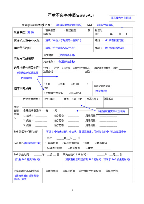
严重不良事件报告表(SAE)填写报告当日日期新药临床研究批准文号:(请填写临床试验批件号)报告类型(打勾)医疗机构及专业名称申报单位名称□首次报告□随访报告结报告(请填“中山大学附属第一医院”)(请填“申办者或 CRO 名称”)编号:□总(填写方案编号)报告时间:年月日电话:(PI 所在科室电话)电话:(申办者联系电话)试验用药品名称药品注册分类及剂型(根据临床试验批件内容填写)临床研究分类姓名拼音缩写 :中文名称:(试验药物全名)英文名称:(试验药物全名)分类:□中药□化学药□治疗用生物制品□预防用生物制品□其它注册分类:剂型 :□Ⅰ期□Ⅱ期□Ⅲ 期Ⅳ期□生物等效性试验□临床验证出生日期 : 性别: □男□女□临床试验适应症:(受试病种)身高(cm):体重(Kg):受试者基本情况合并疾病及治疗:□有1. 疾病: __________2. 疾病: __________3. 疾病: __________□无治疗药物: __________治疗药物: __________治疗药物: __________根据受试者实际状况填写用法用量: _______________用法用量: _______________用法用量: _______________SAE 的医学术语(诊断) 可填 1 个临床诊断,非症状、体征的描述,同时存在多个 AE 应分别报告□ 死亡 ______年___月___ 日SAE 情况(相应项目打勾) □ 导致住院□延长住院时间□伤残□功能障碍□导致先天畸形□危及生命□其它SAE 发生时间: _______年 ___月___ 日研究者获知 SAE 时间: _______年 ___月___ 日(发生 SAE 的具体时间) (研究者被告知或发现 SAE 的时间,可晚于 SAE 发生的时间)对试验用药采取的措施(报告当时对试验药物采取的措施)□继续用药□减小剂量□药物暂停后又恢复□停用药物SAE 转归□ 症状消失(后遗症□有□无) □症状持续(报告当时 SAE 的转归)SAE 与试验药的关系□肯定有关□可能有关□可能无关□肯定无关□无法判定(请尽可能根据临床所 (相关性的判断最好由主要研究者 PI 或次要研究者 sub-Investigator 完成)掌握证据,判断相关性)SAE 报道情况国内:□有□无□不详;国外:□有□无□不详(请根据研究者手册和既往研究经验进行填写)SAE 发生及处理的详细情况:(参考模板)“首次报告”应包含但不限于以下信息,1. 患者入组编号,入组时间和入组临床试验名称(编号),患者诊断和既往重要病史或合并疾病2. 入组后已完成的疗程和发生 SAE 前的末次用药时间3. 发生 SAE 前的相关症状、体征、程度分级,行相关检查和治疗的情况4. 确认为 SAE 后的详细救治过程,有助于证实 SAE 严重性的检查结果等5. 研究者判断该 SAE 与试验用药或方法的相关性6. 其他“随访/总结报告”应包含但不限于以下信息,1. 患者入组编号,入组时间和入组临床试验名称(编号),患者诊断2. 自首次报告后,该 SAE 发生的转归、治疗及相关检查情况3. 再次评价该 SAE 与试验用药或方法相关性4. 明确是否恢复试验治疗或退出试验5. 其他报告单位名称中山大学附属第一医院报告人职务/职称:如实填写报告人签名:首次报告必需由主要研究者签署,如 PI 不在,必需电话告知,并在报告中说明。
USP 通用章节目录

USP29-通用章节指导目录(附录)Guide to General Chapters 通用章节指导目录中此颜色并且带有“***”的为新增内容。
General Requirements for Test and Assays检查与含量分析的一般要求<1>INJECTIONS……2455注射剂<11>USP REFERENCE STANDARDS……2458USP对照品Apparatus for Test and Assays用于检查与含量分析的器具<16>AUTOMATED METHODS OF ANAL YSIS……2491自动化分析方法<21>THERMOMETERS……2497温度计<31>VOLUMETRIC APPARATUS……2497容量器具<41>WEIGHTS AND BALANCES……2499砝码与天平Microbiological Tests 微生物检查法<51>ANTIMICROBIAL EFFECTIVENESS TESTING……2499抗菌剂有效性检查法<55>BIOLOGICAL INDICATORS—RESISTANCE PERFORMANCE TESTS (2501)生物指示剂-耐药性实验<61>MICROBIAL LIMIT TESTS……2503微生物限度检查法<71>STERILITY TESTS……2508无菌检查法Biological tests and assays生物检查法与测定法<81>ANTIBIOTICS—MICROBIAL ASSAYS……2513抗生素-微生物测定<85>BACTERIAL ENDOTOXINS TEST……2521细菌内毒素检查法<87>BIOLOGICAL REACTIVITY TESTS, IN VITRO……2525体外的生物反应性检查法<88>BIOLOGICAL REACTIVITY TESTS, IN VIVO……2526体内的生物反应性检查法<91>CALCIUM PANTOTHENATE ASSAY……2530泛酸钙测定法<111>DESIGN AND ANAL YSIS OF BIOLOGICAL ASSAYS……2531 生物测定法的设计与分析<115>DEXPANTHENOL ASSAY……2543右泛醇(拟胆碱药)测定法<121>INSULIN ASSAYS……2544胰岛素测定法<141>PROTEIN—BIOLOGICAL ADEQUACY TEST……2546蛋白质-生物适应性试验<151>PYROGEN TEST……2546热原检查法<161>TRANSFUSION AND INFUSION ASSEMBLIES AND SIMILAR MEDICAL DEVICES (2547)输血输液用具以及相类似的医疗器械<171>VITAMIN B12 ACTIVITY ASSAY……2548维生素B12活性测定法Chemical Tests and assays化学实验与测定法<181>IDENTIFICATION—ORGANIC NITROGENOUS BASES (2549)鉴别-有机氮碱?<191>IDENTIFICATION TESTS—GENERAL……2550鉴别实验-通用<193>IDENTIFICATION—TETRACYCLINES……2551鉴别-四环素<197>SPECTROPHOTOMETRIC IDENTIFICATION TESTS......2552分光光度计鉴别实验<201>THIN-LAYER CHROMATOGRAPHIC IDENTIFICATION TEST.. (2553)薄层色谱鉴别实验Limit Test 限度检查法<206>ALUMINUM……2554铝<211>ARSENIC……2554砷<221>CHLORIDE AND SULFATE……2555氯和硫<223>DIMETHYLANILINE……2555二甲基苯胺<226>4-EPIANHYDRO-TETRACYCLINE……25564-?-四环素<231>HEA VY METALS……2556重金属<241>IRON……2557铁<251>LEAD……2558铅<261>MERCURY……2558汞<271>READIL Y CARBONIZABLE SUBSTANCES TEST……2560易碳化物检查法<281>RESIDUE ON IGNITION……2560灼烧残渣<291>SELENIUM……2560硒Other Tests and Assays 其它检查法与测定法<301>ACID-NEUTRALIZING CAPACITY……2561酸中和容量<311>ALGINATES ASSAY……2562藻酸盐测定法<331>AMPHETAMINE ASSAY……2562苯丙胺测定法<341> ANTIMICROBIAL AGENTS—CONTENT……2563 抗菌剂-含量<345> Assay for Citric Acid/Citrate and Phosphate……2565 柠檬酸/柠檬酸盐和磷酸盐的测定<351>ASSAY FOR STEROIDS……2565类固醇(甾类化合物)测定法<361> BARBITURATE ASSAY……2565 巴比妥类药物测定法<371>COBALAMIN RADIOTRACER ASSAY……2566钴铵素放射性跟踪剂测定法<381>ELASTOMERIC CLOSURES FOR INJECTIONS……2567 注射剂的弹性密封件<391>EPINEPHRINE ASSAY……2567肾上腺测定法<401>FATS AND FIXED OILS……2568脂肪与混合油<411>FOLIC ACID ASSAY……2571叶酸测定法<425>IODOMETRIC ASSAY—ANTIBIOTICS……2572碘量检查法-抗生素<429>LIGHT DIFFRACTION MEASUREMENT OF PARTICLE SIZE (2572)粒子尺寸的光衍射测量<431>METHOXY DETERMINA TION……2575甲氧基测定法<441>NIACIN OR NIACINAMIDE ASSAY……2576烟酰或烟酰胺测定法<451>NITRITE TITRATION……2578亚硝酸盐滴定<461>NITROGEN DETERMINA TION……2578氮测定法<466>ORDINARY IMPURITIES……2579一般杂质<467>ORGANIC VOLATILE IMPURITIES……2580有机的易挥发杂质<471>OXYGEN FLASK COMBUSTION……2590氧瓶燃烧法<481>RIBOFLAVIN ASSAY……2590核黄素测定法<501>SALTS OF ORGANIC NITROGENOUS BASES……2591有机氮盐<511>SINGLE-STEROID ASSAY……2591单一的类固醇测定法<521>SULFONAMIDES……2592磺胺制剂<531>THIAMINE ASSAY……2593硫胺素测定法<541>TITRIMETRY……2593滴定法<551>ALPHA TOCOPHEROL ASSAY……2596α-维生素E测定法<561>ARTICLES OF BOTANICAL ORIGIN……2596植物起源的药品<563>IDENTIFICATION OF ARTICLES OF BOTANICAL ORIGIN……2603植物药品的鉴别<565>BOTANICAL EXTRACTS……2609植物提取<571>VITAMIN A ASSAY……2611维生素A的测定法<581>VITAMIN D ASSAY……2612维生素D的测定法<591>ZINC DETERMINATION……2616锌的测定法Physical Test and Determinations物理检查与测定法INHALERS, AND DRY POWDER <601>AEROSOLS, NASAL SPRAYS,USP28METERED-DOSEINHALERS……2617气溶胶,鼻用喷雾剂,定量吸入器与干粉吸入器<611>ALCOHOL DETERMINATION……2637乙醇测定法<616>BULK DENSITY AND TAPPED DENSITY……2638堆密度与拍实密度<621>CHROMATOGRAPHY…….2639色谱法<631>COLOR AND ACHROMICITY……2651呈色与消色<641>COMPLETENESS OF SOLUTION……2652完全溶解<643>TOTAL ORGANIC CARBON……2652总有机碳<645>WA TER CONDUCTIVITY……2653水电导率<651>CONGEALING TEMPERA TURE……2654凝点温度<661>CONTAINERS……2655容器<671>CONTAINERS—PERMEATION……2663容器-渗透<691>COTTON……2664棉花<695>CRYSTALLINITY……2665结晶性<696>Crystallinity Determination By Solution Calorimetry……2666 通过溶液量热学测定结晶性<698>DELIVERABLE VOLUME……2667可转移的体积<699>DENSITY OF SOLIDS……2669固体密度<701>DISINTEGRATION……2670崩解时限***<701>Disintegration (Harmonized Chapter, Official April 1,2006)………..2671崩解时限(协调的章节,法定日期,2006.4.1)<711>DISSOLUTION……2673 溶出度***<711>Dissolution (Harmonized Chapter, Official April 1,2006)………..2675 溶出度(协调的章节,法定日期,2006.4.1)<721>DISTILLING RANGE……2682馏程<724>DRUG RELEASE……2682药物释放度***<724>Drug releasee (Harmonized Chapter, Official April 1,2006)………..2690药物释放度(协调的章节,法定日期,2006.4.1)<726>ELECTROPHORESIS……2694电泳<727>CAPILLARY ELECTROPHORESIS……2696毛细管电泳法***<730>Plasma Spectrochemistry….2700 血浆光谱化学<731>LOSS ON DRYING……2704干燥失重<733>LOSS ON IGNITION……2704灼烧失重<736>MASS SPECTROMETRY……2705 质谱<741>MELTING RANGE OR TEMPERATURE……2708熔距或熔点<751>METAL PARTICLES IN OPHTHALMIC OINTMENTS……2709眼用软膏中的金属粒子<755>MINIMUM FILL……2710最低装填量<761>NUCLEAR MAGNETIC RESONANCE……2710核磁共振<771>OPHTHALMIC OINTMENTS……2715眼用软膏<776>OPTICAL MICROSCOPY……2716光学显微镜<781>OPTICAL ROTATION……2718旋光<785>OSMOLALITY AND OSMOLARITY……2718同渗重摩与同渗容摩<786>PARTICLE SIZE DISTRIBUTION ESTIMATION BY ANAL YTICAL SIEVING (2720)通过筛分法估算粒子分布<788>PARTICULATE MATTER IN INJECTIONS……2722注射剂中的颗粒<789>PARTICULATE MATTER IN OPHTHALMIC SOLUTIONS……2729眼用溶液中的颗粒<791>pH (2730)<795>PHARMACEUTICAL COMPOUNDING—NONSTERILE PREPARATIONS (2731)药物混合-非无菌制剂<797>PHARMACEUTICAL COMPOUNDING—STERILE PREPARATIONS (2735)药物混合-无菌制剂<801>POLAROGRAPHY……2752极谱法<811>POWDER FINENESS……2754粉剂细度<821>RADIOACTIVITY……2755放射性<823>RADIOPHARMACEUTICALS FOR POSITRON EMISSION TOMOGRAPHY —COMPOUNDING……2763用于正电子发射断层摄影术的放射性药物<831>REFRACTIVE INDEX……2766折光率<841>SPECIFIC GRA VITY……2766比重<846>SPECIFIC SURFACE AREA……2767 比表面积<851>SPECTROPHOTOMETRY AND LIGHT-SCA TTERING……2770分光光度计与光散射<861>SUTURES—DIAMETER…2775缝线-直径<871>SUTURES—NEEDLE ATTACHMENT……2775缝线-穿孔实验<881>TENSILE STRENGTH…..2776张力<891>THERMAL ANAL YSIS……2776热分析<905>UNIFORMITY OF DOSAGE UNITS……2778制剂单位的含量均匀度<905>UNIFORMITY OF DOSAGE UNITS (Harmonized Chapter, Official April 1,2006)……2780制剂单位的含量均匀度(协调的章节2006.4.1)<911>VISCOSITY……2785粘度<921>WA TER DETERMINA TION……2785水测定法<941>X-RAY DIFFRACTION……2788X光衍射General Information通用信息<1010>ANAL YTICAL DATA—INTERPRETA TION AND TREATMENT (2790)分析数据-解释与处理<1015>AUTOMA TED RADIOCHEMICAL SYNTHESIS APPARATUS (2801)放射性自动合成装置<1031>THE BIOCOMPATIBILITY OF MATERIALS USED IN DRUG CONTAINERS, MEDICAL DEVICES, AND IMPLANTS (2802)用于药物容器、医疗设施和植入剂的材料的生物相容性<1035>BIOLOGICAL INDICATORS FOR STERILIZATION……2811灭菌用生物指示剂<1041>BIOLOGICS……2814生物制剂***<1043>Ancillary Material for Cell, Gene, and Tissue-Engineered Products…….2814 细胞,基因与组织设计产品的辅助材料<1045>BIOTECHNOLOGY-DERIVED ARTICLES……2821生物技术提取产品<1046>CELL AND GENE THERAPY PRODUCTS……2831细胞与基因治疗产品<1047>BIOTECHNOLOGY-DERIVED ARTICLES—TESTS……2858生物技术产品-检查法<1048>QUALITY OF BIOTECHNOLOGICAL PRODUCTS: ANAL YSIS OF THE EXPRESSION CONSTRUCT IN CELLS USED FOR PRODUCTION OF r-DNA DERIVED PROTEIN PRODUCTS1 (2883)生物产品质量:从蛋白质产品中提取的r-DNA产品在细胞中表达结构的分析<1049>QUALITY OF BIOTECHNOLOGICAL PRODUCTS: STABILITY TESTING OF BIOTECHNOLOGICAL/BIOLOGICAL PRODUCTS1 (2884)生物技术产品的质量:生物技术/生物产品的稳定性实验<1050>VIRAL SAFETY EV ALUA TION OF BIOTECHNOLOGY PRODUCTS DERIVED FROM CELL LINES OF HUMAN OR ANIMAL ORIGIN (2887)从人或动物细胞中提取的生物技术产品的病毒安全性评估<1051>CLEANING GLASS APPARATUS……2896玻璃容器的清洗<1061>COLOR—INSTRUMENTAL MEASUREMENT……2896显色-仪器测量***<1065>Ion Chromatography………2898 离子色谱法<1074>EXCIPIENT BIOLOGICAL SAFETY EV ALUA TION GUIDELINES (2900)赋形剂(辅料)生物安全性评估指导<1075>GOOD COMPOUNDING PRACTICES……2903好的混合操作<1078>GOOD MANUFACTURING PRACTICES FOR BULK PHARMACEUTICAL EXCIPIENTS (2906)批药品赋形剂的生产管理规范***<1079>Good Storage and Shipping Practices……2915 良好的贮存与船运规范<1081>GEL STRENGTH OF GELATIN……2920白凝胶的凝胶强度<1086>IMPURITIES IN OFFICIAL ARTICLES……2920药典物品中的杂质<1087>INTRINSIC DISSOLUTION……2923内部的溶出度<1088>IN VITRO AND IN VIVO EV ALUA TION OF DOSAGE FORMS (2924)体内与体外的剂型的评估<1090>IN VIVO BIOEQUIV ALENCE GUIDANCES……29291体内生物等效性指导<1091>LABELING OF INACTIVE INGREDIENTS……2968非活性成分的标示<1101>MEDICINE DROPPER……2969医用滴管<1111>MICROBIOLOGICAL ATTRIBUTES OF NONSTERILE PHARMACEUTICAL PRODUCTS (2969)非无菌药品中的微生物分布<1116>MICROBIOLOGICAL EV ALUA TION OF CLEAN ROOMS AND OTHER CONTROLLED ENVIRONMENTS……2969洁净的房间与其它可控环境的微生物评估<1118>MONITORING DEVICES—TIME, TEMPERATURE, AND HUMIDITY (2976)监控装置-时间、温度与湿度<1119>NEAR-INFRARED SPECTROPHOTOMETRY……2979近红外分光光度测定法***<1120>Raman Spectrophotometry……..2983 Raman分光光度测定法<1121>NOMENCLATURE……2988命名***<1136>Packaging-Unit-of-Use……2989包装-单元使用<1146>PACKAGING PRACTICE—REPACKAGING A SINGLE SOLID ORAL DRUG PRODUCT INTO A UNIT-DOSE CONTAINER……2990 包装操作-将单一固体口服药品产品再包装成单元剂量<1150>PHARMACEUTICAL STABILITY……2994药物稳定性<1151>PHARMACEUTICAL DOSAGE FORMS……2996药物剂型<1160>PHARMACEUTICAL CALCULATIONS IN PRESCRIPTION COMPOUNDING (3006)按处方混合的药物的计算<1171>PHASE-SOLUBILITY ANAL YSIS……3016相溶解分析***<1174>Powder Flow….3017 粉末流动性<1176>PRESCRIPTION BALANCES AND VOLUMETRIC APPARATUS….3020 处方天平与容量器具***<1177>Good Packaging Practices….3021 良好的包装操作***<1178>Good Repackaging Practices….3023 良好的再包装操作<1181>SCANNING ELECTRON MICROSCOPY……3025扫描电子显微镜<1191>STABILITY CONSIDERATIONS IN DISPENSING PRACTICE……3029 分装操作中稳定性考察<1196>PHARMACOPEIAL HARMONIZATION……3031药典的一致性<1207>STERILE PRODUCT PACKAGING—INTEGRITY EV ALUATION (3035)无菌产品包装-完整性评估<1208>STERILITY TESTING—V ALIDATION OF ISOLATOR SYSTEMS (3037)无菌实验-隔离系统的验证<1209>STERILIZATION—CHEMICAL AND PHYSICOCHEMICAL INDICATORS AND INTEGRATORS……3040灭菌-化学与物理化学的指示剂以及二者的综合<1211>STERILIZATION AND STERILITY ASSURANCE OF COMPENDIAL ARTICLES (3041)药典物品中的灭菌与灭菌保证<1216>TABLET FRIABILITY……3046片剂的脆碎度<1221>TEASPOON……3047茶匙<1222>TERMINALL Y STERILIZED PHARMACEUTICAL PRODUCTS—PARAMETRIC RELEASE……3047最终灭菌产品-放行参数<1225>V ALIDATION OF COMPENDIAL METHODS……3050药典方法的验证<1227>V ALIDATION OF MICROBIAL RECOVERY FROM PHARMACOPEIAL ARTICLES (3053)从药物中回收微生物的验证<1230>W ATER FOR HEALTH APPLICATIONS……3055健康用水<1231>W ATER FOR PHARMACEUTICAL PURPOSES……3056制药用水<1241>W ATER–SOLID INTERACTIONS IN PHARMACEUTICAL SYSTEMS (3074)在药物系统中水与固体的相互作用<1251>WEIGHING ON AN ANAL YTICAL BALANCE……3076关于分析天平的称重***<1265>Written Prescription Drug Information-Guidelines……….3078 书面的处方药信息-指南Dietary Supplements营养补充剂General Tests and Assays 一般检查法与测定法<2021>MICROBIAL ENUMERATION TESTS—NUTRITIONAL AND DIETARY SUPPLEMENTS (3080)微生物数量实验-营养与食品添加剂<2022>MICROBIOLOGICAL PROCEDURES FOR ABSENCE OF SPECIFIED MICROORGANISMS—NUTRITIONAL AND DIETARY SUPPLEMENTS (3083)不得检出特定微生物的程序-营养与营养补充剂<2023>MICROBIOLOGICAL A TTRIBUTES OF NONSTERILE NUTRITIONAL AND DIETARY SUPPLEMENTS……3087非无菌的营养与食品添加剂中的微生物分布<2040>DISINTEGRATION AND DISSOLUTION OF DIETARY SUPPLEMENTS (3089)食品添加剂的崩解与溶出<2091>WEIGHT VARIATION OF DIETARY SUPPLEMENTS……3092食品添加剂的重量差异<2750>MANUFACTURING PRACTICES FOR DIETARY SUPPLEMENTS (3093)食品添加剂的生产操作。
TA INSTRUMENTS 00 ARES-G2 ARES-G2 Rheometer 技术参数手册

NSTRUMENTS•New Castle, DE USA +1-302-427-4000•Lindon, Utah USA +1-801-763-1500•Järfälla, Sweden+46-8-564-72-200•Crawley, United Kingdom +44-1293-658900•Shanghai, China +86-21-54263960•Taipei, Taiwan +88-62-25638880•Tokyo, Japan +81-3-5479-8418•Seoul, Korea +82-2-3415-1500•Bangalore, India +91-80-28398963•Paris, France +33-1-30-48-94-60•Eschborn, Germany +49-6196-400-600•Brussels, Belgium +32-2-706-0080•Etten-Leur, Netherlands +31-76-508-7270•Milano, Italy +39-02-27421-283•Barcelona, Spain +34-93-600-9300•Melbourne, Australia +61-3-9553-0813•Mexico City, Mexico+5255-5524-7636L OCAL O FFICESARES-G2P URE• R OBUST•I NDUSTRY S TANDARDORCE R EBALANCE M OTOR ANDM AGNETIC S USPENSIONON-C ONTACT T EMPERATURES ENSOR E LECTRONICSORQUE R EBALANCE M OTORT ORQUE/N ORMAL F ORCER EBALANCE E LECTRONICSR ADIAL A IR B EARINGU PPER G EOMETRY M OUNTARES-G2 T ECHNOLOGYD UCTILE I RONF RAMEARES-G2 E NVIRONMENTAL S YSTEMSThe ARES-G2 offers the convenience of smart swaptemperature control options, which are automaticallydetected and configured when attached.ARS ENSITIVE• V ERSA TILE•R ELIABLE31 64 2AR T ECHNOLOGY The AR series represents a family of rheometers uniquely designed to deliver optimum system performance.The AR-G2 features our new patented Smart Swap Geometries withautomatic detection. Smart Swap geometries include an integratedmagnetic cylinder that stores unique geometry information. Whenttached, the information is automatically read and the software isconfigured with appropriate parameters (type, dimension, material).The Smart Swap option brings the AR-G2 one step closer to being a PRTThe PRT senses temperature at the upper cone or plate geometry, and the signal is transmitted from a secondary coil on the drawrod to a primary coil in the head assembly. Together with a PRT in the lower plate, real-time control of both plates is possible. TheAR-G2 is the first rheometer to actively measure and control the upper plate temperature.26S MART S WAP™ T EMPERATURE S YSTEMSOnly TA Instruments offers the convenience and versatility of Smart Swap temperature control options. Smart Swap temperature control options are attached to the instrument on its unique magnetic base. Intelligent Smart Swap options can be interchanged in as fast as 10 seconds. Once attached, the instrument automatically detects and configures the system.D RY A SPHALT33F LOW C URVE FOR D ISPERSIONSA generalized flow curve for dispersions is illustrated below. TA rheometers generate flow curves by applying a stress ramp (or shear rate) and measuring the shear rate (or stress). Flow curves can also be produced using “steady state” flow where each viscosity data point is generated at a constant stress after equilibration. The data generated provides information on yield stress, viscosity, shear thinning, shear thickening, thixotropy, and correlates to processing and product performance. Simple techniques like spindle viscometers can only measure a point or a small part of the total flow curve. F LOW C URVE FOR P OLYMERSThe figure below shows a generalized flow curve for polymers and corresponding process shear rate ranges. A polymer’s molecular weight greatly influences its zero shear viscosity, while its molecular weight distribution and degree of branching affect its shear rate dependence. These differences are most apparent at low shear rates not possible with melt flow index or capillary devices. TA rheometers can determine molecular weight based on the measured zero shear viscosity. Cox-Merz and TTS can be used to extend the data to higher shear rates.D YNAMIC M ECHANICAL P ROPERTIESOF S OLIDS IN T ORSIONThe ability to characterize the viscoelastic properties of solids in torsion is a feature of TA Instruments’ rheometers, as illustrated below for polycarbonate (PC). Transitions or relaxations of molecular segments are observed as step changes in the storage modulus, and as peaks in the loss modulus and damping. The magnitude and shape of the storage modulus (G), loss m odulus (G) and damping (tan delta) will depend on chemical composition, crystallinity, molecular structure, degree of cross-linking, and the type and amount of fillers. T RANSIENT T ESTS(C REEP AND S TRESS R ELAXATION)In a creep recovery test, illustrated below, a constant stress is applied to the sample and the resulting strain is measured over time. The stress is then removed and the recovery (recoil) strain is measured. For polymer melts, the zero shear viscosity (ηo) and equilibrium recoverable compliance (J eo) can be determined. Creep is a sensitive technique and best suited for the unmatched stress control performance of the AR. In a stress relaxation test, a strain is applied and stress is measured as a function of time yielding stress relaxation modulus G(t). Stress relaxation can be performed on all ARES and on the AR-G2 and AR 2000ex with direct strain controlE XTENSIONAL V ISCOSITY M EASURE -MENTS ON ARESExtensional viscosity is fundamentally important in many polymer-processing techniques such as blow-molding, fiber spinning, and injection molding. The EVF is a polymer melt elongation fixture that transforms an ARES oven system into a shear and extensional rheometer. The EVF uses a unique patented dual cylinder, or drum, wind-up technique. The figure below shows the data on a LDPE sample, superposed with three times the shear and complex viscosity measured at a rate of 0.01 1/s and frequency w = 1/t. The EVF clearly shows excellent data over a wide range of rates.A PPLICATIONSS TRESSANDS HEAR R ATE R AMPSStress and shear rate ramps are common transient experiments that provide fast and easy ways of characterizing yield stress and thixotropic behavior in materials. Both of these phenomena are typical time dependent behaviors of structured fluids that are important for understanding how a material will perform in an application. The stress ramp is a standard way of measuring yield stress of a structured fluid. While ramping the stress linearly with time, the strain and instantaneous viscosity are recorded. It can be seen below that the viscosity increases initially and goes through a maximum. The stress value at the characteristic maximum in viscosity is a measure of the yield stress. Beyond this maximum, the material’s structure breaks and the instantaneous viscosity decreases, or shear thins, with increasing stress. Rate ramps are more commonly used to observe thixotropic behavior.A test procedure involving a shear rate ramp from zero to a final rate and back to zero at constant ramping rate is referred to as thixotropic loop. The magnitude of the stress profile will be lower in higher in the up-ramp then in the down ramp. The area between the up and down stress curves as a function of rate is the called the thixotropic index.41© 2008 TA Instruments. All rights reserved.R2008–ENG。
J1939 protocol英文版_最权威

6COMMUNICATION PROTOCOLSSection Page 6.1OVERVIEW.............................................................................................6-2 6.2SAE J1939MESSAGES AND MESSAGE FORMAT..............................6-26.1OVERVIEWThe key component of the DDEC10system is the serial communication link SAE ing this communication link allows the following functionality:□Transmitting sensor information via the data link at regular intervals and/or upon request to obtain data and to monitor for failures□Sharing information between stand-alone modules used in the system via the data link□Sharing engine data with electronic dashboard displays and vehicle management information systems via the data link□Transmitting and performing diagnostic procedures from external instrumentation such as the hand-held diagnostic data readers or DDDL via the data link□Transmitting customer requested changes to the CPC2+from external instrumentation via the data link□Transmitting to the powertrain the messages assigned to both the engine and the transmission retarder.The following industry standard Society of Automotive Engineers(SAE)documents can be used as a reference:□SAE J1708,Serial Data Communications Between Microcomputer Systems In Heavy Duty Vehicle Applications□SAE J1939/71,Vehicle Application Layer□SAE J1939,Top Layer(Overview)□SAE J1939/01,Truck and Bus Applications□SAE J1939/11,Physical Layer□SAE J1939/21,Data Link Layer□SAE J1939/73,Application Layer DiagnosticsTo obtain a copy of the above documents contact the Society of Automotive Engineers(SAE). SAE International400Commonwealth DriveWarrendale,PA15096Attention:PublicationsPhone:(412)776-49706.2SAE J1939MESSAGES AND MESSAGE FORMATJ1939(+),J1939(-),and J1939Shield are used as the J1939communication link.The message format uses the parameter group number as the label for a group of parameters. Each of the parameters within the group can be expressed in ASCII,as scaled data,or as function states consisting of one or more Bits.Alphanumeric data will be transmitted with the most significant bytefirst.Other parameters consisting of two or more data bytes shall be transmitted least significant bytefirst.The type of data is also identified for each parameter.The following sections identify the parameters that are supported by DDEC10.The J1939source address can be set for various components as listed in the following table.ParameterParameter Options Default Access Group1EBC1Source Address SAE J19390–25533VEPS,DRS 1TSC1Source Address SAE J19390–255231VEPS,DRS 1CC1Source Address SAE J19390–25523VEPS,DRS 1CC2Source Address SAE J19390–25533VEPS,DRS 1CC3Source Address SAE J19390–25549VEPS,DRS 1CM1DPF Source Address SAE J19390–25549VEPS,DRS 1CM1Fan Source Addr1SAE J19390–25549VEPS,DRS 1CM1Fan Source Addr2SAE J19390–25549VEPS,DRS Table6-1J1939Source AddressPGNMessage Name Acronym(dec)From SA61(ACM2):64946Aftertreatment1Intermediate Gas AT1IMG64908Aftertreatment1Gas Parameters AT1GP61455Aftertreatment1Outlet Gas1AT1OG1Table6-2ACM2Address J1939MessagesPGN(dec)Message Name Acronym From SA1(MCM2):65194Alternate Fuel2AF264981Electronic Engine Controller5EEC564931Electronic Engine Controller6EEC664916Electronic Engine Controller7EEC765243Engine Fluid Level/Pressure2EFL/P261450Engine Gas Flow Rate EGF165170Engine Information EI65129Engine Temperature3ET364870Engine Temperature4ET464976Inlet/Exhaust Conditions2IC265244Idle Operation IO65154Ignition Timing1IT165155Ignition Timing2IT265159Ignition Timing6IT665178Turbocharger Information2TCI265177Turbocharger Information3TCI365176Turbocharger Information4TCI465175Turbocharger Information5TCI565245Turbocharger TCTable6-3MCM2Address J1939MessagesPGN (dec)PGN(hex)Message Name Acronym65135FE6F Adaptive Cruise Control ACC1 60928EE00Request For Address Claimed ACL 61183EEFF Address Claimed ACL 65269FEF5Ambient Conditions AMB 65265FEF1Cruise Control Vehicle Speed CCVS 57344E000Cab Message#1CM1 65226FECA Active Diagnostic Trouble Codes DM1 65235FED3Diagnostic Data Clear/Reset for active DTC's DM11 57088DF00Stop Start Broadcast DM13 65228FECC Diagnostic Data Clear DM3 61441F001Electronic Brake Controller#1EBC1 65215FEBF Wheel Speed Information EBC2 61443F003Electronic Engine Controller#2EEC2 61440F000Electronic Retarder Controller#1ERC165281FF02Engine Start Stop(Daimler Prop)ESS(Prop02) 61442F002Electronic Transmission Controller#1ETC1 61445F005Electronic Transmission Controller#2ETC2 65098FE4A Electronic Transmission Controller#7ETC7 55809DB00UDS Functional ISO15765_Funct 55808DA00UDS Physical ISO15765_Phys 61184EF00Proprietary XCP PropA 65280FF00Proprietary UDE PropB00 65530FFFA Proprietary Malaysian H/W Test PropB00 65283FF03Proprietary message KWP Gateway PropB03 65297FF11Proprietary message for FUSO PropB11 65313FF21Proprietary message SAM CAB A1PropB21 65314FF22Proprietary message SAM CAB A2PropB22 65316FF24Proprietary message for FUSO PropB24 65380FF64Proprietary message for Predictive CC PropB64 65381FF65Proprietary message for Predictive CC PropB65 65264FEF0Power Takeoff Information PTO65275FEFB Retarder Fluids RF59904EA00Request PGN RQST 65099FE4B Transmission Configuration#2TCFG2 65132FE6C Tachograph#1TCO1 00Torque Speed Control#1TSC1 65103FEF4Vehicle Dynamic Stability Control1VDC1 Table6-4SAE J1939Supported Incoming CPC2+MessagesPGN (dec)PGN(hex)Message Name Acronym65135FE6F Adaptive Cruise Control#1ACC1 60928EE00Request For Address Claimed ACL 59392E800Ack/Nack ACK/NACK 61183EEFF Address Claimed ACL 61183EEFF Cannot Claim Address ACL 64912FD90Advertised Engine Torque Curve AETC 65269FEF5Ambient Conditions AMB 64947FDB3Aftertreatment Outlet Gas#2AT1OG2 65110FE56Aftertreatment1SCR Tank1Inform AT1T11 65261FEED Cruise Control/Vehicle Speed Setup CCSS 65266FEF1Cruise Control/Vehicle Speed CCVS 65259FEEB Component Identification CI57344E000Cab Message#1CM1 64775FD07Direct Lamp control Command1DLCC1 65226FECA Active Diagnostic Trouble Codes DM1 65227FECB Previously Active Diagnostic Trouble Codes DM2 61441F001Electronic Brake Controller#1EBC1 65251FEE3Engine Configuration EC 61444F004Electronic Engine Controller#1EEC1 61443F003Electronic Engine Controller#2EEC2 65247FEDF Electronic Engine Controller#3EEC3 65214FEBE Electronic Engine Controller#4EEC4 65263FEEF Engine Fluid Level/Pressure#1EFL_P1 65243FEDB Engine Fluid Level/Pressure#2EFL_P2 61440F000Electronic Retarder Controller#1ERC1 65262FEEE Engine Temperature#1ET1 65188FEA4Engine Temperature#2ET2 65213FEBD Fan Drive FD 65253FEE5Engine Hours,Revolutions HOURS 65270FEF6Inlet/Exhaust Conditions#1IC1 64976FDD0Inlet/Exhaust Conditions#2IC2 65244FEDC Idle Operation IO 56064DB00UDS Functional ISO15765_Func 55808DA00UDS Physical ISO15765_Phys 65257FEE9Fuel Consumption LFC 65266FEF2Fuel Economy(Liquid)LFE 64892FD7C Particulate Trap Control#1PTC1 65264FEF0Power Takeoff Info PTO 65249FEE1Retarder Configuration RC 65252FEE4Shutdown SHUTDN 65242FEDA Software Identification SOFT 65245FEDD Turbocharger TC 65132FE6C Tachograph TCO1 65254FEE6Time/Date TD 65248FEE0Vehicle Distance VD 65217FEC1High Resolution Vehicle Distance VDHR 65271FEF7Vehicle Electrical Power VEP 65255FEE7Vehicle Hours VH 65260FEEC Vehicle Information VI 65279FEFF Water in Fuel Indicator WFI 61436EFFC Proprietary XCP PropA65280FF00Proprietary Malaysian H/W Test PropB00 65280FF00Proprietary UDE PropB00 65282FF02Proprietary for FUSO PropB02 65361FF51Proprietary for FUSO PropB51 65376FF60Proprietary for Predictive CC PropB60 Table6-5SAE J1939Supported Outgoing CPC2+Messages6.2.1SAE J1939SUPPORTED MESSAGESThe format of SAE J1939supported messages may be seen in the following sections.6.2.1.1ACC1–Adaptive Cruise ControlReception rate:100msTransmission rate:1secondData length:8bytesData Page:0PDU format:254PDU specific:111PGN:65135(0x00FE6F)Byte:1Speed of Forward Vehicle-N/AByte:2Distance to Forward Vehicle-N/AByte:3Adaptive Cruise Control Set Speed-N/AByte:4ACC Status1Bits:8,7Not DefinedBits:6-4Adaptive Cruise Control Set Distance Mode-N/ABits:3-1Adaptive Cruise Control Mode(SPN1590)110:Error111:Not AvailableByte:5–6Road Curvature-N/AByte:7Bits:8,7Not DefinedBits:5,6ACC Distance Alert Signal–N/ABits:3,4ACC System Shutoff Warning–N/ABits:1,2ACC Target Detected–N/AByte:8Not Defined6.2.1.2ACK/NACK–Acknowledge/Negative Acknowledge Transmission Rate:As NeededData Length:8bytesData Page:0PDU format:232PDU specific:Destination AddressDefault priority:6PGN:59,392(0x00E800)Byte:1Control Byte0:Positive Acknowledgment(ACK)1:Negative Acknowledgment(NACK)2:Access Denied(PGN supported but access denied) Byte:2Group Function Value(if applicable)-N/ABytes:3–5Reserved for assignment by SAE,send each of these bytes as“FF”Byte:6–8Parameter Group Number of requested information6.2.1.3AETC-Advertised Engine Torque CurveTransmission RepetitionRate:N/AData Length:VariableData Page:0Extended Data Page:0PDU format:253PDU specific:144PGN Supporting Information:Default priority:6PGN:64,912(0xFD90)Start Position Length Parameter Name SPN 1.14bits AETC Data CollectionStandard35581.54bits Number of AETC datapoints3559a2bytes AETC Speed Value3560b2bytes AETC Torque value35616.2.1.4AMB–Ambient ConditionsTransmission Rate:1sec.Data Length:8bytesData Page:0PDU format:254PDU specific:245Default priority:6PGN:65,269(0x00FEF5)Byte:1Barometric Pressure(SPN108)Resolution:0.5kPa/Bit,0kPa offsetByte:2Cab Interior Temperature-N/ABytes:4,5Ambient Air Temperature(SPN171)Resolution:0.03125°C/Bit,-273°C offsetByte:6Air Inlet Temperature(SPN172)Resolution:1°C/Bit,-40°C offsetBytes:7,8Road Surface Temperature-N/A6.2.1.5ATI2-Aftertreatment Intake Gas2Transmission Repetition Rate:500msData Length:8bytesExtended Data Page:0Data Page:0PDU format:253PDU specific:180Default priority:6PGN:64948(0xFDB4)Bytes:1–2Exhaust Gas Temperature1(SPN3241)–N/ABytes:3–4Particulate Trap Intake Gas Temperature(SPN3242)(CPC2+Rel2or later) Resolution:0.03125°C/Bit,-273°C offsetByte:5Exhaust Gas Temperature1Preliminary FMI(SPN3243)–N/AByte:6Particulate Trap Intake Exhaust Gas Temperature Preliminary FMI–N/A6.2.1.6ATO2-Aftertreatment Outlet Gas2Transmission Repetition Rate:500msData Length:8bytesExtended Data Page:0Data Page:0PDU format:253PDU specific:179Default priority:6PGN:64947(0xFDB3)Bytes:1–2Exhaust Gas Temperature3(SPN3245)–N/ABytes:3–4Particulate Trap Outlet Gas Temperature(SPN3246)(CPC2+Rel2or later) Resolution:0.03125°C/Bit,-273°C offsetByte:5Exhaust Gas Temperature3Preliminary FMI(SPN3247)–N/AByte:6Particulate Trap Outlet Exhaust Gas Temperature Preliminary FMI–N/A 6.2.1.7CCSS–Cruise Control/Vehicle Speed SetupTransmission Rate:On RequestData Length:8bytesData Page:0PDU format:254PDU specific:237Default priority:6PGN:65,261(0x00FEED)Byte:1Maximum Vehicle Speed Limit(SPN74)Resolution:1km/h/Bit,0km/h offsetByte:2Cruise Control High Set Limit Speed.(SPN87)Resolution:1km/h/Bit,0km/h offsetByte:3Cruise Control Low Set Limit Speed(SPN88)Resolution:1km/h/Bit,0km/h offsetBytes:4-8Not Defined6.2.1.8CCVS–Cruise Control/Vehicle SpeedTransmission/Reception Rate:100msData Length:8bytesData Page:0PDU format:254PDU specific:241Default priority:6PGN:65,265(0x00FEF1)Byte:1Measured_SW1Bits:8,7Not DefinedBits:6,5Cruise Control Pause Switch(SPN1633)00:Off01:On10:Error11:Take No ActionBits:4,3Parking Brake Switch(SPN70)00:Park Brake Not Set01:Park Brake Set10:Error11:Not ConfiguredBits:2,1Two Speed Axle Switch(SPN69)00:Low Speed Range01:High Speed Range10:Error11:Not ConfiguredByte:2,3Wheel Based Vehicle Speed(SPN84)Resolution:1/256km/h,0km/h OffsetByte:4Measured_CC_SW1Bits:8,7Clutch Switch(SPN598)00:Clutch Pedal Released01:Clutch Pedal Depressed10:Error11:Not ConfiguredBits:6,5Service Brake Switch(SPN597)00:Brake Pedal Released01:Brake Pedal Depressed10:Error11:Not ConfiguredBits:4,3Cruise Control Enable Switch(SPN596)00:Cruise Control Disabled01:Cruise Control Enabled10:Error11:Not ConfiguredBits:2,1Cruise Control Active(SPN595)00:Cruise Control Off01:Cruise Control On10:Error11:Not ConfiguredByte:5Measured_CC_SW2Bits:8,7Cruise Control Accelerate Switch(SPN602)00:Accelerate Switch Off01:Accelerate Switch On10:Error11:Not ConfiguredBits:6,5Cruise Control Resume Switch(SPN601)00:Resume Switch Off01:Resume Switch On10:Error11:Not ConfiguredBits:4,3Cruise Control Coast Switch(SPN600)00:Coast Switch Off01:Coast Switch On10:Error11:Not ConfiguredBits:2,1Cruise Control Set Switch(SPN599)00:Set Switch Off01:Set Switch On10:Error11:Not ConfiguredByte:6Cruise Control Set Speed(SPN86)Resolution:1km/h/Bit,0km/h OffsetByte:7State_CCBits:8–6Cruise Control State(SPN527)000:Off/Disabled001:Hold010:Accelerate011:Decel/Coast100:Resume101:Set110:Accelerator Override111:Not AvailableBits:5-1PTO State-(SPN976)00000:Disabled/Off00001:Hold00010:Remote Hold00100:Remote Standby00101:Set00110:Decelerate/Coast00111:Resume01000:Accelerate01001:Accelerator Override01010:Programmed Speed101011:Programmed Speed201100:Programmed Speed311111:Not AvailableByte:8Measured_Idle_SW1Bits:8,7Engine Shutdown Override Switch(SPN1237)00:Switch Off01:Switch On11:Not ConfiguredBits:6,5Engine Test Mode Switch–N/ABits:4,3Idle Decrement Switch(SPN967)00:Off01:OnBits:2,1Idle Increment Switch(SPN968)00:Off01:On6.2.1.9CI–Component IdentificationTransmission Rate:On RequestData Length:37bytesData Page:0PDU format:254PDU specific:235Default priority:6PGN:65,259(0x00FEEB)Bytes:1-5Make(SPN586)–ASCIIByte:6*-DelimiterBytes7–14:Engine Model Number(SPN587)–ASCIIByte:15*-DelimiterByte:16–25Engine Serial Number(SPN588)–ASCIIByte:26*-DelimiterByte:27–36Unit Number(Power Unit)(SPN233)-ASCIIByte:37*-DelimiterNote:DDEC10also supports an alternate format of the component identification data to satisfy an AGS2transmission.6.2.1.10CM1–Cab Message1 TransmissionRate:1sec.Data Length:8bytesData Page:0PDU Format:224PDU Specific:218Default Priority:6PGN:57,344(0x00E00016)Byte:1Requested Percent Fan Speed(SPN986)Resolution:0.4%/Bit,0offsetBytes:2–3Cab Interior Temperature Command–N/AByte:4Bits:2–1Auxiliary Heater Coolant Pump Request–N/ABits:4–3Battery Main Switch Hold Request–N/ABits:6–5Operator Seat Direction Switch–N/ABits:8–7Seat Belt Switch–N/AByte:5Bits:8–7Vehicle Speed Governor Enable Switch—N/ABits:6–5Vehicle Limiting Speed Governor Increment Switch–N/ABits:4–3Vehicle Limiting Speed Governor Decrement Switch–N/ABits:2–1Not DefinedByte:6Bits:4–3Particulate Trap Regeneration Force Switch(SPN3696)00:Not Active01:Active10:Error11:Not AvailableBits:2–1Particulate Trap Regeneration Inhibit Switch(SPN3695)00:Not Active01:Active10:Error11:Not AvailableByte:7Bits:8–7Request Cab Zone Heating—N/ABits:6–5Request Engine Zone Heating–N/ABits:4–1Auxiliary Heater Mode Request–N/AByte:8Selected Maximum Vehicle Speed Limit–N/A6.2.1.11DD-Dash Display(PGN65276(R)Reception Rate:1sData Length:8Extended Data Page0Data Page:0PDU Format:254PDU Specific:252Default Priority:6PGN:65276(0xFEFC)Byte:1Washer Fluid Level(SPN80)-N/A Byte:2Fuel Level1(SPN96)Resolution:0.4%bit,0offsetByte:3Engine Fuel Filter Differential Pressure(SPN95)-N/AByte:4Engine Oil Filter Differential Pressure(SPN99)-N/AByte:5-6Cargo Ambient Temperature(SPN169)-N/AByte:7Fuel Level2(SPN38)-N/A6.2.1.12DM1–Active Diagnostic Trouble CodesTransmission/ Reception Rate:Whenever a DTC becomes an active fault and at a normal update rate of one second or longer,and then becomes inactive,a DM1message will be transmitted to reflect this state change.If a different DTC changes state within one second update period,a new DM1message is transmitted to reflect this new DTC.Data Length:VariableData Page:0PDU Format:254PDU Specific:202Default Priority:6PGN:65226(0x00FECA)Byte:1Bits:8–7Malfunction Indicator Lamp Status(SPN1213)00:Lamp Off01:Lamp On10:Error11:Not AvailableBits:6–5Red Stop Lamp Status(SPN623)00:Lamp Off01:Lamp On10:Error11:Not AvailableBits:4–3Amber Warning Lamp Status(SPN624)00:Lamp Off01:Lamp On10:Error11:Not AvailableBits:2–1Protect Lamp Status(SPN987)–N/AByte:2Bits:8–1Reserved for SAE assignment Lamp Status Byte:3Bits:8–1SPN,8least significant bits of SPN(SPN1214)(most significant at bit8)Byte:4Bits:8–1SPN,second byte of SPN(most significant at bit8)Byte:5Bits:8–6SPN,3most significant bits(most significant at bit8)Bits:5–1FMI(SPN1215)(most significant at bit5)Byte:6Bit:8Bits:7–1SPN Conversion Method(SPN1706) Occurrence Count(SPN1216)Byte:7Bits:8–1Not Defined Byte:8Bits:8–1Not Defined6.2.1.13DM2–Previously Active Diagnostic Trouble CodesTransmission Rate:On RequestData Length:VariableData Page:0PDU Format:254PDU Specific:203Default Priority:6PGN:65227(0x00FECB)Byte:1Bits:8–7Malfunction Indicator Lamp Status(SPN1213)00:Lamp Off01:Lamp On10:Error11:Not AvailableBits:6–5Red Stop Lamp Status(SPN623)00:Lamp Off01:Lamp On10:Error11:Not AvailableBits:4–3Amber Warning Lamp Status(SPN624)00:Lamp Off01:Lamp On10:Error11:Not AvailableBits:2–1Protect Lamp Status(SPN987)–N/AByte:2Bits:8–1Reserved for SAE Assignment Lamp StatusByte:3Bits:8–1SPN,8least significant bits of SPN(most significant at bit8)(SPN1214)Byte:4Bits:8–1SPN,second byte of SPN(most significant at bit8)(SPN1214)Byte:5Bits:8–6SPN,3most significant bits(most significant at bit8)(SPN1214)Bits:5–1FMI(most significant at bit5)(SPN1215)Byte:6Bit:8SPN conversion Method(SPN1706)Bits:7–1Occurrence count(SPN1216)Byte:7Bits:8–1Not DefinedByte:8Bits:8–1Not Defined6.2.1.14DM3-Diagnostic Data Clear/Reset of Previously Active DTCsReception Rate:On Request using PGN59904Data Length:0Data Page:0PDU Format:254PDU Specific:204Default Priority:6PGN:65,228(0x00FECC)Note:All of the non-permanent diagnostic information pertaining to previously active(inactive) visible diagnostic trouble codes will be erased when this PG is requested.The diagnostic data associated with active trouble codes will not be affected.Upon reception of this PG request, DDEC10will respond with a Positive Acknowledgement(ACK).This message clears both CPC2+and MCM2previously active DTCs.6.2.1.15DM11—Diagnostic Data Clear/Reset for Active DTCsReception Rate:On Request Using PGN59904Data Length:0Data Page:0PDU Format:254PDU Specific:211Default Priority:6PGN:65,235(0x00FED3)Note:All of the non-permanent diagnostic information pertaining to active visible diagnostic trouble codes will be erased when this PG is requested.The diagnostic data associated with previously active(inactive)trouble codes will not be affected.Upon reception of this PG request,DDEC10will respond with a Positive Acknowledgement(ACK).This message clears both CPC2+and MCM2previously active DTCs.6.2.1.16DM13—Stop Start BroadcastReception Rate:As ReceivedData Length:8bytesData Page:0PDU format:223PDU specific:Destination AddressDefault priority:3PGN:57,008(0x00DF00)Byte:1SAE Primary LinksBits:8,7Current Data Link(SPN1230)00:Stop Broadcast01:Start Broadcast11:Don't Care00:Stop Broadcast01:Start Broadcast11:Don't CareBits:4,3J1922(SPN622)–N/ABits:2,1J1939Network#1,Primary Vehicle Network(SPN639)00:Stop Broadcast01:Start Broadcast11:Don't CareByte:2Other Networks#1Bits:8,7J1939Network#2-N/ABits:6,5ISO9141-N/ABits:4,3J1850-N/ABits:2,1Other,Manufacture Specified Port-N/AByte:3Other Networks#2Bits:8,7J1939Network#3-N/ABits:6–1Not DefinedByte:4Control FlagsBits:8–5Hold Signal(SPN1236)0000:All Devices0001:Devices whose broadcast state has been modified0010–1110:Not Defined1111:N/ABits:4–1Suspended Signal–N/AByte:5–6Suspended Duration–N/AByte:7–8SAE Reserved6.2.1.17EBC1–Electronic Brake Controller#1 Transmission/Reception Rate:100msData Length:8bytesData Page:0PDU format:240PDU specific:1Default priority:6PGN:61,441(0x00F001)Byte:1Status EBC1Bits:1-2ASR Brake Control Active–N/ABits:3-4Anti-Lock Braking(ABS)Active(SPN563)Bits:5-600:ABS Passive but installed 01:ABS Active10:Reserved11:Not AvailableBits:7-8EBS Brake Switch–N/AByte:2Brake Pedal Position–N/AByte:3Status EBC2Bits:1-2ABS Off-Road Switch–N/ABits:3-4ASR Off-Road Switch–N/ABits:5-6ASR“Hill Holder”Switch–N/ABits:7-8Traction Control Override Switch–N/A Byte:4Measured Aux.1Bits:1-2Accelerator Interlock Switch–N/ABits:3-4Engine Derate Switch–N/ABits:5-6Auxiliary Engine Shutdown Switch–N/ABits:7-8Remote Accelerator Enable Switch(SPN969)00:Off01:OnByte:5Engine Retarder Selection(SPN973)Resolution:0.4%/Bit,0%OffsetByte:6EBC Lamp Status–N/AByte:7Source Address of Controlling Device for Brake Control–N/A Byte:8Not Defined6.2.1.18EBC2–Wheel Speed InformationReception Rate:100msData Length:8bytesData Page:0PDU format:254PDU specific:191Default priority:6PGN:65,215Bytes:1,2Front Axle Speed(SPN904)Resolution:1/256km/h per bit,0offset Byte:3Relative Speed,Front Axle,Left Wheel–N/A Byte:4Relative Speed,Front Axle,Right Wheel–N/A Byte:5Relative Speed,Front Axle#1,Left Wheel–N/A Byte:6Relative Speed,Front Axle#1,Right Wheel–N/A Byte:7Relative Speed,Front Axle#2,Left Wheel–N/A Byte:8Relative Speed,Front Axle#2,Right Wheel–N/A 6.2.1.19EC–Engine ConfigurationTransmission Rate:5sec.Data Length:34bytesData Page:0PDU format:254PDU specific:227Default priority:6PGN:65,251(0x00FEE3)Bytes:1,2Engine Speed At Idle,Point1(SPN188)Resolution:0.125rpm/Bit,0rpm offset Byte:3Percent Torque At Idle,Point1(SPN539)Resolution:1%/Bit,-125%offsetBytes:4,5Engine Speed At Point2(SPN528)Resolution:0.125rpm/Bit,0rpm offset Byte:6Percent Torque At Point2(SPN540)Resolution:1%/Bit,-125%offsetBytes:7,8Engine Speed At Point3(SPN529)Resolution:0.125rpm/Bit,0rpm offset Byte:9Percent Torque At Point3(SPN541)Resolution:1%/Bit,-125%offsetBytes:10,11Engine Speed At Point4(SPN530)Resolution:0.125rpm/Bit,0rpm offsetByte:12Percent Torque At Point4(SPN542)Resolution:1%/Bit,-125%offsetBytes:13,14Engine Speed At Point5(SPN531)Resolution:0.125rpm/Bit,0rpm offsetByte:15Percent Torque At Point5(SPN543)Resolution:1%/Bit,-125%offsetBytes:16,17Engine Speed At High Idle,Point6(SPN532)Resolution:0.125rpm/Bit,0rpm offsetBytes:18,19Engine Gain(KP)Of Endspeed Governor-N/ABytes:20,21Reference Engine Torque(SPN544)Resolution:1Nm/Bit,0Nm offsetByte:22,23Maximum Momentary Engine Override Speed,Point7(SPN533) Resolution:0.125rpm/Bit,0rpm offsetByte:24Maximum Momentary Engine Override Time Limit(SPN534) Resolution:0.1s/Bit,0s offsetByte:25Requested Speed Control Range Lower Limit-300RPM–N/A Byte:26Requested Speed Control Range Upper Limit–N/AByte:27Requested Torque Control Range Lower Limit–N/AByte:28Requested Torque Control Range Upper Limit–N/AByte29,30Extended Range Requested Speed Control Range Upper Limit —N/AByte31,32Engine Moment of Inertia(SPN1794)Resolution:0.004kgm2/Bit,0kgm2/Bit Offset Byte33,34Default Engine Torque Limit—N/A6.2.1.20EEC1–Electronic Engine Controller#1 Transmission Rate:10msData Length:8bytesData Page:0PDU format:240PDU specific:4Default priority:3PGN:61,444(0x00F004)Byte:1Status_EEC1Bits:8-5Not DefinedBits:4-1Engine/Retarder Torque Mode(SPN899)0000:Low Idle Governor0001:Accelerator Pedal0010:Cruise Control0011:PTO Governor0100:Road Speed Governor0101:ASR Control0110:Transmission Control0111:ABS Control1000:Torque Limiting1001:High Speed Governor1010:Braking System1011:Remote Accelerator-N/A1100:Not Defined1101:Not Defined1110:Other1111:Not AvailableByte:2Drivers Demand Engine-Pct Torque(SPN512)Resolution:1%/Bit,-125%offsetByte:3Actual Engine-Percent Torque(SPN513)Resolution:1%/Bit,-125%offsetBytes:4,5Engine Speed(SPN190)Resolution:0.125rpm/Bit,0rpm offsetByte:6Source address of controlling device for engine control(SPN1483)Byte:7Bits:8–5Not DefinedBits:1–4Engine Starter Mode(SPN1675)0000:Start Not Requested0001:Starter Active,Gear Not Engaged0010:Starter Active,Gear Engaged0011:Start Finished;Starter Not Active After Having Been ActivelyEngaged0100:Starter Inhibited Due To Engine Already Running0101:Starter Inhibited Due To Engine Not Ready For Start(preheating)0110:Starter Inhibited Due To Driveline Engaged Or OtherTransmission Inhibit0111:Starter Inhibited Due To Active Immobilizer1000:Starter Inhibited Due To Starter Over-Temp1001-1011:Reserved1100:Starter Inhibited-Reason Unknown1101:Error1110:Error1111:Not AvailableByte:8Engine Demand–Percent Torque(SPN2432)Resolution:1%/Bit,-125%offset6.2.1.21EEC2–Electronic Engine Controller#2 Transmission/Reception Rate:50msData Length:8bytesData Page:0PDU format:240PDU specific:3Default priority:3PGN:61,443(0x00F003)Byte:1Status_EEC2Bits:8-7Accelerator Pedal2Low Idle Switch—N/ABits:6-5Road Speed Limit Status(SPN1437)00:Active01:Not ActiveBits:4-3AP Kickdown Switch(SPN559)00:Kickdown Passive01:Kickdown Active11:Not ConfiguredBits:2,1AP Low Idle Switch(SPN558)00:Not In Low Idle Condition01:In Low Idle Condition10:Error Detected11:Not ConfiguredByte:2Accelerator Pedal Position(TPS)(SPN91)Resolution:0.4%/Bit,0%offsetByte:3Percent Load At Current Speed(SPN92)Resolution:1%/Bit,0%offsetByte:4Remote Accelerator(SPN974)Resolution:0.4%/Bit,0%offsetByte:5Accelerator Pedal Position2(SPN29)—N/AByte:6Vehicle Acceleration Rate Limit StatusBits:8–3Not DefinedBits:2–1Vehicle Acceleration Limit Status(SPN2979)00:Limit Not Active01:Limit Active10:Reserved11:Not DefinedByte:7Actual Maximum Available Engine percent Torque–(SPN3357) Byte:8Not Defined6.2.1.22EEC3–Electronic Engine Controller#3Transmission Rate:250msData Length:8bytesData Page:0PDU format:254PDU specific:223Default priority:6PGN:65,247(0x00FEDF)Byte:1Nominal Friction-Percent Torque(SPN514)Resolution:1%/Bit,-125%OffsetBytes:2,3Engine's Desired Operating Speed(SPN515)Resolution:0.125rpm/Bit,0rpm OffsetByte4:Engine's Desired Operating Speed Asymmetry Adjustment(SPN519) Ratio:0to250Byte5:Engine Controlled Cooling Fan Losses–Percent Torque(SPN2978) Resolution:1%/Bit,-125%OffsetByte:6–7Exhaust Gas Mass(SPN3236)—N/AByte:8After-TreatmentBits:7-8After-Treatment Intake Dew Point Message–N/ABits:5-6After-Treatment Exhaust Dew Point Message–N/ABits:3-4After-Treatment Intake Dew Point Message–N/ABits:1-2After-Treatment Exhaust Dew Point Message–N/A 6.2.1.23EEC4–Electronic Engine Controller#4Transmission Rate:On RequestData Length:8bytesData Page:0PDU format:254PDU specific:190Default priority:7PGN:65,214(0x00FEBE)Bytes:1,2Rated Engine Power(SPN166)Resolution:0.5kW/Bit,0kW offset(0.67hp/Bit,0hp offset)Bytes:3,4Rated Engine Speed(SPN189)Resolution:0.125rpm/Bit,0rpm offset Bytes:5-8Not Defined。
三丰surftest sj-301便携式粗糙度测试仪使用手册说明书
•The large LCD window makes it easy to readmeasurement resultand analysis graph at a glance. The profile-speed thermal printer prints out clear and fast.•Designed to increaseoperability – the large keypads are used for measuringoperations, while the touch panelLCD is used for setting various measurement conditions.•Measured data can be downloaded to a PC. Various analyses can be made by using Surfpak-SJ, dedicated software for surface texture analysis.A portable surface roughness testerwith a touch-panel LCD and a built-in printer.Surftest SJ-301Conforming to various standards•Conforming to the JIS (1994/1982),ISO, DIN, and ANSI standards.•Additionally, the horizontal roughness parameters S, Sm, tp (mr) can be reported. The SJ-301 also performs such special parameters as plateau rate and RK-related parameters.Storing measurement conditions and data•The SJ-301 main unit can store a maximum of 5 sets of measuring conditions. Individual measuring conditions can be selected for each workpiece.•The measuring conditions stored in the SJ-301 can be recalled and switched by direct key operations.•Measured data can be saved at the measurement site and be printed out or recalculated later.•By using an optional memory card, a maximum of 20 sets of measuring conditions, measured data, and statistical results can be stored.High-speed thermal printer•Equipped with a highly sophisticated,high-speed thermal printer.•Selectable orientation for printout –Choose the portrait for conventional printout or the landscape for printing out the image as it is displayed.•BAC (Bearing Area Curve) and ADC (Amplitude Distribution Curve) can be printed out.Key-masking function•This function limits touch panel operation to prevent the detector calibration data and measuring conditions from being altered or deleted.•Measuring conditions can be easily controlled among multiple users.Landscape printoutPortrait printoutResistance to environment•The SJ-301 keypads have excellentdurability -- No need to worry about oil stains from the user's hand.Reading profiles in the LCD window•Measurement results and analysis profiles can be read in the LCD window.•Signal waves can be scrolled smaller or larger, enabling the operator to read fine details.Customization function•The user can select only theparameters needed from a variety of surface roughness parameters provided.Mobility•A built-in buttery in the SJ-301 makes it possible to inspect surface roughness even at a site where there is no electrical outlet available.•Portable and convenient – the drive unit and the detector can be stored in the display unit. (Carrying case is a standard accessory.)•Measurement can be performed while the display unit is in the carrying case.The carrying case can be used to protect the display unit.Auto calibration•Calibration can be easily performed by simply inputting and measuring the Ra value inscribed on the roughness reference specimen.•No adjustment with a tool, such as a volume adjustment, etc. is required.Statistical analysis functions•Statistical analysis of one parameter is possible.•Displays and prints frequency histograms as well as statisticalcalculation results (average, standard deviation, maximum value, minimum value, pass ratio).GO/NG judgement function•Tolerance values in three-steps can be set for the surface roughness parameters.•Judgment symbol is displayed in the result display for a quick judgment of GO/NG.Selectable language for display/printoutDisplay/printout language is selectable from among English, German, French,Italy, Spanish and Japanese.Surftest SJ-301 Arbitrary evaluationlength•An arbitrary evaluation length withinthe range of 0.3 mm - 12.5 mm (Unit:0.1 mm) can be set.•Measurement in a limited space, wheremeasurement is difficult under themeasuring conditions in accordancewith JIS standards, is made possible byusing the start-up OFF function.One-step detectorreplacement•Special detectors are available formeasurements that cannot beperformed with a standard detector -such as measurement of small-diameters and deep-grooves.•No tool is required for replacing thedetector. Simply pull out and insert adetector.•Just one SJ-301 can performmeasurement on a variety ofworkpieces, since various types ofdetectors, depending on theworkpiece, can be used.25.2mm (.99")Approx. 21mm (.83")horizontallyApprox. 2mm (.08")verticallyHigh-accuracy detector•SJ-301 employs a differentialinductance method, which is used inhigh-end models.•Measurement with a high-accuracyand a wide measuring range of350µm.•Parameters that require high-accuracyfeed such as Sm and S can bemeasured with the SJ-301.•The detector can be retracted into thedrive unit when the SJ-301 is notperforming a measurement.room to build a highly expandable desktop evaluation system.Surftest SJ-301Specifications**Evaluation length can be specified arbitrary in the range from 0.3mm (.01”) to 12.5mm (.49”).Roughness specimenSurftest SJ-301MichiganPhone: (734) 459-2810IllinoisPhone: (630) 978-5385CaliforniaPhone: (626) 961-9661MassachusettsPhone: (978) 692-8765IndianaPhone: (317) 577-6070North CarolinaPhone: (704) 875-8332Coordinate Measuring Machines Small Tool Instruments and Data ManagementHardness Measuring Sensor Systems Optical Measuring Digital Scale and DRO Systems Surface-, Form- and Contour MeasurementVision Measuring Systems Note: All information regarding our products, and in particular the illustrations, drawings, dimensional and performance data contained in this pamphlet, as well as other technical data are to be regarded as approximate average values. We therefore reserve the right to make changes to the corresponding designs, dimensions and weights. The stated standards, similar technical regulations, descriptions and illustrations of the products were valid at the time of printing. In addition, the latest applicable version of our General Trading Conditions will apply. Only quotations submitted by ourselves may be regarded as definitive.Job No.11B-7。
01-SAMSS-035
Materials System Specification2008June01-SAMSS-035 29API Line PipeMaterials and Corrosion Control Standards Committee MembersAnezi, Mohammed Ali, ChairmanRumaih, Abdullah Mohammad, Vice ChairmanAbdul Hadi, Abdul Latif IbrahimBannai, Nabeel SaadBuraiki, Iyad AbdulrazzakBurgess, Brian WayneCruz, Czar Ivan TecsonKermad, AbdelhakLobley, Graham RusselMehdi, Mauyed SahibMoore, Mark AndrewMugbel, Wajdi MohammadNasri, Nadhir IbrahimNiemeyer, Dennis CharlesNuaim, Tareq AbdulazizOmari, Ahmad SalehRao, SanyasiTems, Robin DouglasSaudi Aramco DeskTop StandardsTable of ContentsScope (2)III Conflicts and Deviations (2)References (2)IIIIV Modifications to API SPEC 5L (4)Appendix B – Repair of Defects by Welding (16)Appendix F – Supplementary Requirements (16)Previous Issue: 19 August 2007 Next Planned Update: 17 January 2012Revised paragraphs are indicated in the right margin Page 1 of 18Primary contact: Anezi, Mohammed Ali on 966-3-8760229Next Planned Update: 17 January 2012 API Line PipeI ScopeThis Specification covers seamless and submerged-arc welded (SAW), straight-seamand spiral-seam, steel line pipe manufactured in accordance with API Specification 5L (43rd Edition, 2004) to Product Specification Level 2. Unless stated in the purchaseorder, all pipes shall be suitable for sour service.Spiral-seam SAW pipe shall be limited to nominal diameter size of 16 inches or larger.Unless stated to the contrary in the Purchase Order, pipe manufactured to thisspecification must be suitable for external coating with fusion bonded epoxy per09-SAMSS-089. If the pipe will be internally coated 09-SAMSS-091 shall be followed, and this requirement shall be so stated in the Purchase Order. See paragraphs 4.2, 7.5and 7.8.14.II Conflicts and DeviationsA. Any conflicts between this specification and other applicable Saudi AramcoMaterials System Specifications (SAMSSs), Engineering Standards (SAESs),Standard Drawings (SASDs), or industry standards, codes, and forms shall beresolved in writing by the Company or Buyer Representative through theManager, Consulting Services Department of Saudi Aramco, Dhahran.B. Direct all requests to deviate from this specification in writing to the Company orBuyer Representative, who shall follow internal company procedure SAEP-302and forward such requests to the Manager, Consulting Services Department ofSaudi Aramco, Dhahran.III ReferencesThe manufacture and purchase of material covered by this specification shall complywith the latest edition of the references listed below, as noted.A. Saudi Aramco ReferencesSaudi Aramco Engineering ProcedureObtaining a Waiver of aforSAEP-302 InstructionsMandatory Saudi Aramco EngineeringRequirementSaudi Aramco Materials System Specifications01-SAMSS-016Qualification of Pipeline and Pressure VesselSteels for Resistance to Hydrogen-InducedNext Planned Update: 17 January 2012 API Line PipeCracking01-SAMSS-022Fracture Control Testing Procedures for LinePipe09-SAMSS-089Shop-Applied External Fusion Bonded EpoxyCoating for Steel Line Pipes09-SAMSS-091Qualification Requirements for Shop-AppliedInternal FBE CoatingsSaudi Aramco Standard DrawingAB-036386Hardness Testing for Welding ProcedureSaudi Aramco Inspection RequirementsForm 175-010700Pipe: Beveled End, Seamless or Submerged ArcWelded, Straight or Spiral Seam, Carbon SteelPipe Size ≥ 6"B. Industry Codes and StandardsAmerican Petroleum InstituteAPI SPEC 5L Specification for Line PipeAmerican Society of Mechanical EngineersASME SEC IX Qualification Standard for Welding and BrazingProcedures, Welders, Brazers, and Weldingand Brazing OperatorsAmerican Society for Nondestructive Testing, Inc.ASNT SNT-TC-1A Recommended Practice for PersonnelQualification and CertificationASNT CP-189 Standard for Qualification and Certification ofNondestructive Testing PersonnelAmerican Society for Testing and MaterialsASTM A20 General Requirements for Steel Plates forPressure VesselsASTM A106 Seamless Carbon Steel Pipe for High-Temperature ServiceASTM G39 Practice for Preparation and Use of Beam StressCorrosion Test SpecimenNext Planned Update: 17 January 2012 API Line Pipe ASTM E92 Test Method for Vicker Hardness of MetallicMaterialsASTM E112 Standard Test Methods for Determining AverageGain SizeASTM E709 Standard Guide for Magnetic ParticleExaminationInternational Organization for StandardizationISO 9000 - 9004 Quality Management and Quality AssuranceStandardsISO 12094 Welded Steel Tubes for Pressure Purposes-Ultrasonic Testing for the Detection ofLaminar Imperfections in the Strip/Plates Usedin the Manufacture of Welded TubesISO 13663 Welded Steel Tubes for Pressure Purposes-Ultrasonic Testing of the Area Adjacent to theWeld Seam for the Detection of LaminarImperfectionsISO 3183-3 Petroleum and Natural Gas Industries-Steel Pipesfor Pipelines- Part 3: Pipes of RequirementClass CNACE MR0175/ Petroleum and Natural Gas Industries MaterialsISO 15156 for Use in H2S-Containing Environments in Oiland Gas ProductionIV Modifications to API SPEC 5LThe following paragraph numbers refer to API SPEC 5L, which is the basis of thisspecification. The text in each paragraph below is an addition or modifications toAPI SPEC 5L, as noted. Paragraph numbers not appearing in API SPEC 5L are newparagraphs to be inserted in numerical order.1.2 Product Specification Level [modification]All pipes shall be manufactured to PSL 2, with the additional requirementscontained in this specification.[modification]1.3 GradesPipe manufactured as Grade X60 or X65 (for sour and non-sour) may besubstituted for a lower grade if it meets all requirements for the lower gradeexcept maximum yield strength. API SPEC 5L Grade X70 may beNext Planned Update: 17 January 2012 API Line Pipe substituted for a lower strength grade only for non-sour service. The pipeshall be marked with the actual grade.Commentary Note:Maximum design metal temperature limitation established in ASME pipingcode for X-grade pipe shall be noted when substituting the B-grade pipe.4 Information to be Supplied by the Purchaser4.2 Optional Requirements [addition]Indicate in the Purchase Order only when required:a) Suitable for internal coating; automatic welding required.(See Scope, 7.2, 7.5, and 7.8.14)b) Suitable for automatic welding (See 7.2)c) Qualification for resistance to hydrogen-induced cracking(See Appendix F)d) Non-sour service (See 10.1.4)5 Process of Manufacture and Material5.1 Process of Manufacture [addition]Welded pipe shall be made by the automatic submerged-arc process (fusionwelded) in accordance with API SPEC 5L, paragraphs 5.1.3.5 or 5.1.3.11with a minimum of two welding passes on the outside and one on the inside.(Use of two or more wires is accepted as equal to two welding passes). Forwall thickness 7.9 mm and less, one outside welding pass may be acceptableupon approval by the Buyer. Double seam pipe is not acceptable for sizesmaller than 60 inch nominal diameter. The steel shall be fully killed andshall conform to the fine grain size requirement of ASTM A20.5.1.1 Seamless Process [addition]Seamless Grade B pipe shall meet the requirements of ASTM A106 inaddition to the requirements of API SPEC 5L and this specification. Theprimary compatibility item is the requirement for killed steel and 0.10%minimum silicon content. For other properties, the more restrictivespecification applies in each case.Exception:For pipe size 14 and larger, not for automatic welding, O.D. tolerances on thepipe body and ends shall be in accordance with API SPEC 5L only.Next Planned Update: 17 January 2012 API Line Pipe The manufacturing processes and Inspection Tests Plan (ITP) shall besubmitted prior to the start of work to Saudi Aramco Vendor InspectionDivision/Quality Control Unit for approval.5.1.2 Welding Processes [addition]The manufacturing Welding Procedure Specification (WPS) shall document,as a minimum, all essential variables listed in API SPEC 5L, Appendix C,and those listed below. A complete product test as required by API SPEC5L shall verify that the WPS is acceptable. The actual material details andwelding parameters shall be documented in a Procedure QualificationRecord (PQR).All testing shall be in compliance with this standard.A Only electrodes and fluxes identified on the WPS shall be used.B All electrodes and fluxes shall be properly stored to prevent moistureabsorption, as recommended by the electrode and flux manufacturer.C When making the skelp end weld for spiral welded pipe, runoff forstart and stop may extend up to one inch at either end onto the basemetal.D Repair welding procedures for the weld seam shall meet the essentialrequirements and testing of API SPEC 5L, Appendix B & C, or ASMESEC IX, at the option of the manufacturer. Only electrodes identifiedon the repair welding procedure shall be used.E The welding procedures shall be available for review by Saudi Aramcorepresentative upon request.F The manufacturer, trade name and type of weld wires and fluxes usedfor the PQR shall be specified on the WPS as essential variables.G The heat input specified on the WPS shall not be less than 90% of thatqualified by the production test and shall not exceed that qualified bythe production test.H Recycling of crushed slag or contaminated flux is not permitted.I Every batch of "G" consumable, if used, will receive a product test.J The manufacturing welding process is limited to submerged arcwelding (SAW).5.1.3 Tack Weld (Modification): Tack welds shall be limited to Gas Metal ArcWelded (GMAW) and Flux Cored Arc Welding (FCAW) and such weldingNext Planned Update: 17 January 2012 API Line Pipe conditions shall be recorded and appear as part of the production weldingprocedure.5.2 Cold Expansion [addition]SAW straight-seam pipe shall be cold expanded at least 0.8% of the pipecircumference, but shall not exceed 1.5%.Heat-treatment of pipe may be used in lieu of cold expansion, provided thatheat treatment does not cause any adverse effect on the mechanicalproperties and pipe roundness.Commentary Note:Cold expansion of 0.8% - 1.2% has been found effective in controlling pipedimensional and roundness tolerances, and minimizing residual stressesresulted from pipe forming and welding operation.Requirements6 Material6.1.1 Chemical Composition [modification]The product analysis shall not exceed the following:Silicon : .0.38% for SAW and 0.40% for seamlessTitanium : 0.04%Vanadium : 0.08%Boron content shall be shown in the heat analysis or product analysis andshall not exceed 0.0005%.Equivalent6.1.3 CarbonCarbonEquivalent [modification]6.1.3.2 MaximumThe carbon equivalent shall not exceed the maximum limits tabulated below,unless approved by the Chairman of the Saudi Aramco Welding StandardsCommittee or the Chairman of the Saudi Aramco Materials and CorrosionControl Standards Committee.Next Planned Update: 17 January 2012 API Line PipeWall Thickness(mm) Maximum C.E.(IIW) ValueFor C > 0.12%Maximum C.E.(Pcm) ValueFor C ≤ 0.12%≤ 9.5 0.43 0.2412.7 0.40 0.2215.9 0.39 0.2219.1 0.37 0.2122.2 0.36 0.2025.4 0.34 0.1931.8 0.35 0.1938.1 0.36 0.2044.5 0.37 0.2150.8 0.38 0.22The maximum C.E. value for intermediate wall thickness shall beinterpolated linearly.If a C.E. deviation from the above table is accepted for any order, each pipelength shall be marked in accordance with paragraph 10.1 showing the actualC.E. value. The value shall be marked on each end on both the I.D. andO.D. (i.e., four locations).For thicknesses in excess of 50.8 mm, the C.E. value shall be proposed bythe vendor and shall be approved by the Chairman of the Saudi AramcoWelding Standards Committee or the Chairman of the Saudi AramcoMaterials and Corrosion Control Standards Committee. The C.E. value shallbe marked on each pipe as described in the paragraph above.6.2.1 Tensile Properties [addition]The finished pipe (after all heat treatment and expanding or sizingoperations) shall conform to the requirements of Paragraph 6.2.1 inAPI SPEC 5L for the grade as indicated in the Purchase Order.6.2.5.3 Supplementary Fracture Toughness Tests [addition]Fracture toughness tests shall be made in accordance with the requirementsof 01-SAMSS-022 when indicated in the Purchase Order. If 01-SAMSS-022 is specified, the Purchase Order shall also indicate the Class of fluidservice and for Class IV shall specify the API SPEC 5L SR5B minimumaverage absorbed energy requirement. All tests shall be conducted at 0°Cunless stated otherwise in the purchase order.Next Planned Update: 17 January 2012API Line Pipe 6.3 Macro Residual Stress Test [addition]Spiral welded pipe shall meet the testing and minimum acceptance criterionset forth in this paragraph. The residual stress test shall be done after thehydrostatic test.6.3.1 Test FrequencyOne specimen shall be tested for each grade, size and wall thickness at thebeginning of production. In addition, the first produced pipe shall be testedafter changing the production line equipment settings.6.3.2 Test SpecimenThe specimen consists of a 150 mm wide ring cut from the end of a pipe,Figure 2. The specimen may be either flame cut or sawed from the parentpipe.6.3.3 TestingThe specimen ring shall be cut, by flame or sawing, parallel to thelongitudinal axis. The cut shall be 180 degrees from the spiral weld. Priorto cutting the ring, fiducial marks shall be placed on either side of theproposed cut location.6.3.4 Computation of Macro Residual StressThe change in circumference after cutting shall be measured using thefiducial marks established on the specimen prior to severing. The assumed residual stress shall be computed using the following formula.2R 566.12C t E =S (1) where: S = residual stress in MPa (psi)C = ± change in circumference, mm (in)t = nominal thickness, mm (in)E = 200,000 MPa (29 x 106 psi)R = nominal pipe radius mm (in)6.3.5 Acceptance CriterionThe computed macro residual stress shall not exceed ±10% of the specifiedminimum yield strength of the pipe.Next Planned Update: 17 January 2012 API Line Pipe6.3.6 RetestsRetest criteria are the same as for tensile tests. (See API SPEC 5L 9.12.2)6.3.7 ReportingAll residual stress results shall be recorded as part of the mill report.6.4 Hardness Tests [addition]6.4.1 Hardness tests shall be conducted on cross-section samples of finished pipe.For sizes up through 12 inches nominal diameter, test one pipe per 200lengths. For sizes greater than 12 inches nominal diameter, test one pipe per100 lengths. For all sizes, test at least one pipe per heat.6.4.2 At least one transverse specimen shall be removed from each tested pipelength. The specimen shall be polished.6.4.3 For seamless pipe, at least four hardness measurements shall be made ineach of the following locations on the polished specimen cross-sections:a) 1.5 mm -0 + 0.5 mm from the O.D. surfaceb) 1.5 mm -0 + 0.5 mm from the I.D. surface,c) at the midwall.(Total of 12 indentations)6.4.4 For SAW pipe, hardness measurements shall be made at 1.5 mm ± 0.5 mmfrom the O.D. and from the I.D. surfaces. Each traverse shall consist ofindentations in accordance with Figure 1, as follows:a) Two indentations in the weld metalb) Three indentations in the heat-affected zones on both sides of the weld,andc) Two indentations in the parent metal on both sides of the weld.6.4.5 Only Vickers hardness testers shall be used. The maximum hardnessmeasured shall not exceed 250 HV using 5 or 10 kg load.6.4.6 Retest criteria are the same as for tensile tests. (See API SPEC 5L 9.12.2and 9.13)6.5 Sour Service [Addition]Welded pipe (SAW), intended for sour service shall conform to therequirements of 01-SAMSS-016.Next Planned Update: 17 January 2012 API Line Pipe7 Dimensions, Weights, Lengths, Defects, and End Finishes[addition]7.2 Diameter7.2.1 On SAW pipe, local out-of-roundness (deviation from the normal cylindricalcontour) in the form of peaking or flattening of the seam shall not exceed3.0 mm. See 7.2.3 below.7.2.2 Pipe that is to be joined using pipeline field automatic welding systemsPipe that is designated in the Purchase Order as "Suitable for AutomaticWelding" shall meet the following additional requirements:(a) For straight seam or spirally welded pipe, the outside weldreinforcement shall be ground flush at the weld seam with the pipesurface for a minimum longitudinal distance of 130 mm from each endof the pipe. After grinding, wall thickness dimension shall be nominalplus or minus API allowable tolerances.Commentary Note:Removal of outside weld reinforcement from the pipe ends is needed tofacilitate the movement of the automatic ultrasonic probe as part ofpipeline field automatic welding requirement.(b) The difference in outside or inside diameter, at the ends, between anytwo lengths of the same Line Item shall not exceed 1.6 mm for 75% ofthe pipes produced.(c) Out-of-Roundness at the ends shall not exceed 1.0% of specified(nominal) O.D. For pipe with D/t < 75, the difference betweenmaximum diameter and minimum diameter shall not exceed 6 mm.(d) On SAW pipe for automatic welding, local out-of-roundness (deviationfrom the normal cylindrical contour) in the form of peaking orflattening of the seam shall not exceed 1.6 mm at the end of the pipe.See 7.2.3 below.7.2.3 One acceptable method of determining local out-of-roundness ismeasurement of the maximum gap between a template and the pipe exterior.The template must conform to a circle of the pipe's nominal diameter and thelength of the template must be one-fourth of the nominal diameter, exceptthat it need not be over 200 mm. Weld reinforcement may be removed forthe measurement or the template may have a groove to accommodate theweld seam or another reliable alternative method shall be used. For spiral-seam pipe, a 200 mm straight template parallel to the pipe axis may be used.Next Planned Update: 17 January 2012 API Line Pipe[modification]7.5 Length7.5.1 Length shall be as specified in the Purchase Order, with tolerances shown inAPI SPEC 5L Table 11 unless specified otherwise (see 7.5.3). If the lengthis not specified in the Purchase Order, 12-meter lengths shall be suppliedwith tolerances shown in API SPEC 5L Table 11, except that:a) No pipe lengths less than 10.0 m will be accepted.b) Pipe lengths less than 11.6 m shall not exceed 2% of the total line itemquantity.c) If the pipe is identified in the Purchase Order as being intended forsubsequent internal coating, the maximum length of any individualpipe shall be 12.8 m.7.5.2 The total length of pipe supplied per item on an order shall not be less thanthe amount ordered and shall not exceed the amount ordered by more thanthree lengths, except by agreement. Quantity tolerances for very smallorders are by agreement between the manufacturer and BuyerRepresentative.7.5.3 For pipes intended for subsea applications, the pipe length shall be 12.2 m(40 ft) nominal length. No pipe shall be longer than 12.8 m (42 ft) norshorter than 11.6 m (38 ft). These length restrictions shall be stated in thepurchase order.7.8 Workmanship and Defects7.8.14 Other Defects [addition]For pipe that is intended to be subsequently coated (See Section I), thesurfaces to be coated shall be essentially free of scabs, slivers, cold laps,burrs or other surface defects that would impair the coating.Inclusions or particles that are detrimental to welding, including tungstencarbide inclusions rolled into the surface, shall be considered to be defectsregardless of depth and processed as permitted by API SPEC 5L.9 Inspection and Testing [addition]Pipe purchased in accordance with this Specification is subject to therequirements of API SPEC 5L Appendix H and Saudi Aramco InspectionRequirements Form 175-010700.Tests9.4 HydrostaticNext Planned Update: 17 January 2012 API Line Pipe9.4.3 Test Pressures [modification]Each length of pipe shall be given a mill hydrostatic test at the pressureindicated in the Purchase Order, or, in the absence of such a pressure in thePurchase Order, not less than the pressure necessary to obtain a hoop stressequal to 90% of the specified minimum yield strength of the material. Pipefurnished from Vendor inventory may be accepted with the standard API testpressure by negotiation.The hydrostatic test shall be conducted after all manufacturing processes(including repairs and heat treatments) are completed.Commentary Note:Grinding repair per API SPEC 5L to remove discontinuity is acceptable afterhydrostatic test.Inspection9.8 Nondestructive9.8.1 Qualification of Personnel [addition]NDT personnel shall be qualified to ASNT SNT-TC-1A Level 1 or 2according to their responsibilities. Level 1 personnel may set up theequipment, perform tests, and report the results. Supervision of Level 1personnel and interpretation of results shall be done by Level 2 employees.The primary Level 3 employee such as company employee, outsideconsultant, or third party inspector shall be certified in accordance withASNT CP-189 or by an independent certifying body acceptable to SaudiAramco. Working practice for qualification shall be submitted to SaudiAramco for approval.9.8.3 Methods of Inspection (Weld Inspection) [modification]The full length of every welded seam shall be examined as required byAPI SPEC 5L paragraph 9.8.3 except that fluoroscopic examination is notacceptable. If this examination is done before the hydrostatic test, theBuyer's Inspector may, at his sole discretion, require re-examinations bymanual ultrasonic method of any questionable areas after the hydrostatictest. Means shall be provided to mark the pipe when the nondestructiveinspection equipment indicates an imperfection is present so that anomalousareas can be readily identified.Locations showing indications above the allowable limits may be re-examined by the manual ultrasonic method. If no defects are located duringre-examination, the original findings may be ignored.Next Planned Update: 17 January 2012 API Line Pipe Additional scanning may be required by the Buyer's Representative to checkquestionable areas.9.8.5.7 Ultrasonic Testing for the detection of laminar imperfection on thestrip/plate edges [addition]9.8.5.7.1 The plate/strip edges or areas adjacent to the weld seam shall be 100%ultrasonically inspected over a minimum band width of 25 mm for thedetection of laminar imperfections. The testing method shall be conductedin accordance with ISO 12094 or ISO 13663, as appropriate. Theacceptance limits shall be in accordance with Table D.2 of ISO 3183-3.Commentary Note:This testing is required to prevent blocking of the ultrasonic testing beamduring weld inspection.9.8.5.7.2 Ultrasonic Testing for the detection of laminar imperfection on the pipebody [addition]The coverage of lamination detection shall be at least 25% of pipe surface.The acceptance criteria for laminar imperfection detected in sour and non-sour pipe shall be in accordance with Table D.2 of ISO 3183-3. Plates orskelps shall be ultrasonically inspected for laminations throughout the body,spaced 75 mm on center when scanning parallel to the major plate axis or100 mm on center when scanned perpendicular to the major plate axis.Other equivalent search patterns may be used upon approval of the Buyer.Locations showing indications above the allowable limits may be re-examined by the manual ultrasonic method. If no defects are located duringre-examination, the original findings may be ignored.9.8.5.7.3 Full body rotary ultrasonic inspection of the finished pipes is an acceptablealternative to ultrasonic inspection of the plate or skelp. The acceptancecriteria in paragraph 9.8.5.7.2 above shall apply.9.9 Disposition of pipe containing defects [modification]: All rejected pipesshall be identified and segregated separately from acceptable pipes inaccordance with ISO 9000 - 9004.10 Marking[addition]10.1 GeneralThe area of the pipe to be marked shall be clean and dry. The markings shallbe paint stenciled using a medium and protective varnish that will provide alegible marking for at least one year of outside storage. The varnish coatingNext Planned Update: 17 January 2012 API Line Pipe shall be hard drying and the dry film thickness should not exceed 50micrometers. The size of the lettering shall be commensurate with thediameter of the pipe, but in no case less than 19 mm in height for APImarkings and 13 mm in height for shipping markings.10.1.4 Marking of Non-sour Service Pipe [addition]SAW pipe purchased for non-sour service shall be identified by painting awhite longitudinal stripe, 50 mm wide by 450 mm long, on the inside surfaceof both ends. This stripe is intended to provide identification until the pipeis installed.10.3 Sequence of Markings [addition]Each pipe shall be marked Saudi Aramco, followed by the destination,Purchase Order number/Item Number, heat number, and the Saudi Aramco9COM or 9CAT stock number. If there is no assigned 9COM or 9CATstock number, the pipe shall be marked "01-SAMSS-035."10.3.10 Supplementary Requirements [addition]For pipe which has been impact tested to 01-SAMSS-022, the class indicatedin the Purchase Order shall be included in the markings.Example: To indicate pipe that has been impact tested for Saudi AramcoService Class IV, mark it: "01-SAMSS-022 Class IV".11.1 CoatingsPipe shall be supplied without mill coating unless specified otherwise inPurchase Order.RevisionSummary17 January 2007 Major revision.3 July 2007 Editorial revision to delete Section V.19 August 2007 Minor revision.29 June 2008 Editorial revision to remove reference to SAES-A-301 and replaced with NACEMR0175/ISO 15156.Next Planned Update: 17 January 2012 API Line PipeAppendix B – Repair of Defects by WeldingB.1.2 Weld Seam of Welded PipeB.1.2.1 [modification] Defects in the weld after cold expansion shall not be repairedbut rejected unless the section of pipe containing the defect can be cut offwithin the limits of requirements on lengths.Appendix F – Supplementary RequirementsSR15 Test Certificates and Traceability for Line Pipe [addition]Three copies of the required certificate(s) in the English language shall befurnished to Buyer's Representative. In addition to the data specified in SR15.1, the following information is required:1) A report of the residual stress tests required by paragraph 6.3 of thisSpecification for spiral welded pipe.2) Hardness test results (Refer to paragraph 6.4).3) Verification of compliance with paragraph 7.2.2 for automatic welding.SR HIC Qualification for resistance to hydrogen-induced cracking shall be per01-SAMSS-016 when indicated in the Purchase Order. This requirementdoes not apply to seamless pipe. (See 4.2)。
线粒体膜电位检测
UNIT7.32 Uncompensated Polychromatic Analysisof Mitochondrial Membrane PotentialUsing JC-1and Multilaser ExcitationSara De Biasi,1Lara Gibellini,1and Andrea Cossarizza11Department of Surgery,Medicine,Dentistry and Morphological Sciences,University ofModena and Reggio Emilia,Modena,ItalyThe lipophilic cation JC-1(5,5ʹ,6,6ʹ-tetrachloro-1,1ʹ,3,3ʹ-tetraethyl-benzimidazolyl carbocyanine iodide)has been used for more than20yearsas a specific dye for measuring mitochondrial membrane potential( m).Inthis unit,we revise our original protocol(that made use of a single488nmlaser for the detection of monomers and aggregates,and where compensationwas an important step)to use dual-laser excitation.Moreover,thanks torecently developed multilaser instruments and novel probes for surface andintracellular markers,JC-1can be utilized by polychromaticflow cytometryto simultaneously detect,without any compensation betweenfluorescences,m along with other biological parameters,such as apoptosis and theproduction of reactive oxygen species.C 2015by John Wiley&Sons,Inc.Keywords:apoptosis r mitochondrial membrane potential r JC-1r polychro-maticflow cytometry r Annexin V r CellRoxHow to cite this article:De Biasi,S.,Gibellini,L.,and Cossarizza,A.2015.UncompensatedPolychromatic Analysis of Mitochondrial Membrane PotentialUsing JC-1and Multilaser Excitation.Curr.Protoc.Cytom.72:7.32.1-7.32.11.doi:10.1002/0471142956.cy0732s72INTRODUCTIONThe dissipation of the mitochondrial transmembrane potential( m)constitutes anearly and irreversible step in the cascade of events that,in several cell types,can lead toprogrammed cell death(apoptosis)(Galluzzi et al.,2012).Several probes are available to measure m byflow cytometry,but some of them havea low specificity for this organelle;conflicting data in the literature about the role ofm dissipation during the apoptotic process could be,at least in part,ascribed to thislack of specificity.After excitation with a blue laser at488nm,thefluorescent dye5,5ʹ,6,6ʹ-tetrachloro-1,1ʹ,3,3ʹ-tetraethyl-benzimidazolyl carbocyanine iodide(JC-1),a lipophilic cation ex-isting in a monomeric form,emits in the green region.However,in mitochondriathat have a high m,JC-1forms so called J-aggregates,described almost80yearsago(Jelley,1936),and undergoes a reversible change influorescence emission fromgreen to ing commonflow cytometers equipped with such lasers,for sev-eral years mitochondria have been studied by detecting the two emissions of JC-1by the normalfilters present in FL1(for monomers)and FL2(for aggregates)(Cos-sarizza et al.,1993;Cossarizza et al.,1995;Polla et al.,1996;Cossarizza et al.,1997;Salvioli et al.,2000;Cossarizza et al.,2002;Lugli et al.,2007;Troiano et al.,2007; Gibellini et al.,2012;Abu et al.,2014;Marringa et al.,2014;also see older version Current Protocols in Cytometry7.32.1-7.32.11,April2015Published online April2015in Wiley Online Library().doi:10.1002/0471142956.cy0732s72Copyright C 2015John Wiley&Sons,Inc.Nucleic Acid Analysis7.32.1 Supplement72of this unit at /doi/10.1002/0471142956.cy0732s41/full).Measurements using this dye provide information on changes in m(typically,adecrease in m causes a relevant shift from orange to greenfluorescence emis-sion),as well as on total mitochondrial content(based on the intensity of the greenfluorescence emission).A number of studies have since shown the superiority ofJC-1over other dyes—e.g.,rhodamine123(R123)or3,3ʹ-dihexyloxadicarbocyanineiodide[DiOC6(3)]—that were used for the same purpose,and demonstrated thatJC-1is also unaffected by changes in plasma membrane potential(Salvioli et al.,1997;Lugli et al.,2007;Troiano et al.,2007;also see older version of this unit at/doi/10.1002/0471142956.cy0732s41/full).This unit discusses a new method to detect JC-1(see Basic Protocol1),based upon theuse of two lasers,one to excite JC-1monomers(by the canonical488-nm laser line),and the other to excite JC-1aggregates(by a yellow laser emitting at561nm).Thetypical excitation by the blue laser excites JC-1with high efficiency,but sometimesrequires significant compensation between FL1and FL2.In contrast,yellow laser allowsa better resolution,and thus a clearer visualization of monomers and aggregates withoutcompensation(Perelman et al.,2012).For this reason,we have revised our basic JC-1protocol using the two different lasers quoted above.Furthermore,we have recently developed another polychromaticflow cytometric assay(see Basic Protocol2)utilizing JC-1and other probes for the simultaneous detection of m,reactive oxygen species(ROS,by CellRox DeepRed),and apoptosis(by Annexin V,detecting the exposure of phosphatidylserine on the plasma membrane).This protocolcan be applied when the simultaneous analysis of multiple parameters during apoptosisis required,e.g.,in investigating the role of certain proteins on cell phenotype or whentesting the cytotoxicity of compounds of pharmacological interest.CAUTION:For the protection of laboratory personnel from potential infectious agents (e.g.,hepatitis and HIV),handle human samples using disposable gloves in a biological safety cabinet.CAUTION:All probes described in this unit are potentially hazardous(see manufacturers’MSDSs),and users should wear gloves during the staining procedures.BASIC PROTOCOL1BASIC DETERMINATION OF MITOCHONDRIAL MEMBRANE POTENTIAL USING JC-1:DUAL-LASER EXCITATION OF THE DYEA VOIDS COMPENSATION ISSUESThis protocol is intended for cells such as peripheral blood mononuclear cells(PBMCs)or cell lines such as RKO,HL60,MCF7,and U937.Other cell types may also be stainedusing minor adjustments to the steps described below.Typically,by using a488-nm blue laser,it can be observed that cells with high m(that form JC-1aggregates)emit orangefluorescence(atß590nm);those with low m(containing JC-1in its monomeric form)emit greenfluorescence(atß520nm) (Cossarizza et al.,1993).Recently it has been demonstrated that alternative excitationwavelengths can facilitate the detection of m,and,most importantly,use of twowavelengths avoids the need for compensation.Indeed,the excitation wavelength561nm(i.e.,yellow laser)is above the emission spectra of JC-1monomers,and selectivelyexcites J-aggregates;hence there is no need to compensate green and orangefluorescence(Perelman et al.,2012).Thus,we have adapted our original protocol(that made use ofa single488-nm laser,and where compensation was an important step)to an instrumentequipped with a blue and a yellow laser(like the Attune NxT,from Life Technologies).Analysis ofMitochondrialMembranePotential UsingJC-1andMultilaserExcitation7.32.2Supplement72Current Protocols in CytometryMaterialsExperimental samples:human peripheral blood lymphocytes or monocytes,orhuman tumor cell lines(e.g.,RKO,HL60,U937,MCF7);here we use RKOcells,which derive from a colon carcinoma and grow adherent to the plasticflask Complete RPMI culture medium,1ml per sample1M valinomycin[dissolve valinomycin(mol.wt.1111.32;Sigma-Aldrich)indimethylformamide(DMF)and store in a glass container up to6months at4°C]or1mM carbonyl cyanide p-(trifluoromethoxy)phenylhydrazone(FCCP;Sigma Aldrich)2.5mg/ml JC-1(5,5ʹ,6,6ʹ-tetrachloro-1,1ʹ,3,3ʹ-tetraethylbenzimidazolyl-carbocyanine iodide):prepare by dissolving JC-1(Life Technologies,ThermoFisher Scientific)in dimethylformamide(DMF);store in a glass container up to2years at–20°C,protected from lightPhosphate-buffered saline(PBS)3.5-ml,55×12–mm plastic tubes(Sarstedt,or equivalent)Centrifuge(Minifuge RF;Heraeus),or equivalentFlow cytometer equipped with a488-nm blue laser and with a561-nm yellow laser,e.g.,Attune NxT(Life Technologies)Additional reagents and equipment for counting(APPENDIX3A)and culturing(APPENDIX3B)mammalian cellsPrepare cells1.Count a sample of the experimental cells of interest(APPENDIX3A).This protocol can be used to stain either cells growing in suspension or adherent cellsafter they have been released from the plate by trypsinization(APPENDIX3B)and counted(APPENDIX3A).2.Collect at least2×105cells from the experimental samples in55×12–mm tubesby centrifuging5min at300×g,room temperature.Collect the same number ofcells to use for a positive control.3.Decant and discard the medium and resuspend the cell pellet in1ml fresh completeRPMI culture medium.4.For obtaining a so-called“positive control,”i.e.,a sample where all cells have de-polarized mitochondria,prepare one sample of cells treated with valinomycin(finalconcentration0.1μM)or with carbonyl cyanide p-(trifluoromethoxy)phenylhydra-zone(FCCP,final concentration250nM).Incubate10min or45min,respectively,at37°C.Drugs such as the K+ionophore valinomycin or the proton translocator FCCP are ableto collapse theΔΨm.Note that to avoid problems related to intracellular drug metabolism,in some instancesvalinomycin is preferred over FCCP or ClCCP(and is also less expensive).Stain with JC-15.Add1μl of2.5mg/ml JC-1fluorescent probe(2.5μg/mlfinal concentration)to theexperimental and positive control cells and shake the cell suspension until the dyeis well dispersed and gives a uniform red-violet color.JC-1tends to form aggregates when added to normal aqueous medium.To avoid this,add the probe while gently vortexing.6.Incubate the samples10min in the dark,37°C.Nucleic AcidAnalysis7.32.3 Current Protocols in Cytometry Supplement72Figure 7.32.1Changes in JC-1fluorescence after mitochondrial membrane depolarization in RKO cells treated with valinomycin,as described in Basic Protocol 1.Samples were acquired using 488-nm laser only (A ),or with dual-laser excitation (B ).Control cells (CTR)were stained with 2.5μg/ml JC-1.Note the shift to the bottom and to the right of cells with mitochondria depolarized by treatment with 100nM valinomycin.Right panel shows the merging of the left and center panels.Green-orange compensation was ß4%and orange-green compensation was ß10%;compensation was required to better visualize monomers and aggregates.All reagents must be at room temperature and carefully checked for pH (7.4)when used,because ΔΨm is very sensitive to alterations of these conditions.The staining procedure must be carried out away from direct intense light,and incubation must be in the dark because of the light sensitivity of JC-1.7.Wash the cells by centrifuging 5min at 300×g ,room temperature,discarding the supernatant,and resuspending the cells in 1ml PBS for analysis on cytometer.Set up flow cytometer 8.Detect JC-1fluorescence of the experimental and positive control samples using a classical green band-pass filter centered at 525/50nm for monomers detection (channel of blue laser)and a classical greenish orange band-pass filter centered at 585/42nm (usually those for a channel collecting fluorescence signals deriving from the excitation with the blue or the yellow laser).The most common flow cytometers are typically equipped with only a 488-nm argon or solid-state laser;no special requirements are needed to analyze ΔΨm .The gain of photomultipliers (PMTs)obviously depends on the cytometer used,but generally JC-1does not require any substantial increase in PMT amplification;green-orange compensation can be ß4%and orange-green compensation ß10%.However,note that no compensation is needed if a blue and a yellow laser are used to detect monomers and aggregates,respectively.See Figure 7.32.1for a typical example of JC-1staining of control (CTR)RKO cells,and of RKO cells treated with valinomycin.Detection was performed by using a single blue laser (A)or using blue and yellow lasers (B).This treatment results in a relevant change in the fluorescence distribution:cells with depolarized mitochondria can be easily identified as those going from the center of the plot to the lower right quadrant.Analysis ofMitochondrial Membrane Potential UsingJC-1andMultilaser Excitation7.32.4Supplement 72Current Protocols in Cytometry9.On the basis of the laser used,adjust the voltage of the respective PMTs to obtainthe bivariate green versus orange distributions similar to those shown in Figure7.32.1A and B,and then record the control e the same PMT settings forthe subsequent samples.Analyze JC-1stained experimental samples10.Acquire fluorescence data for experimental samples in listmode,using a log scalefor the fluorescence channels.Cells with high ΔΨm are those forming J-aggregates;thus,they show high orangefluorescence.On the other hand,cells with low ΔΨm are those in which JC-1maintains (orre-acquires)its monomeric form,and thus show green fluorescence.Once mitochondriaare depolarized,JC-1monomers redistribute in other membranous compartments withlower ΔΨ.As a consequence,the green fluorescence intensity of depolarized cells is alittle bit higher than that of polarized ones simply because of the presence of a higheramount of JC-1monomers inside the cell.11.Recommended for samples with heterogeneous cell populations:Set a gate on thepopulation of interest,then proceed with adjustment of PMTs,as well as compen-sation if a 488-nm laser is used.Dual-laser excitation of the dye does not requirecompensation.When the sample contains a heterogeneous cell population,it is possible to see differentfluorescence patterns due to different autofluorescences and the variable content in termsof membranes and mitochondria of cell subpopulations.This is the case for peripheralblood mononuclear cells (PBMCs),lymphocytes,and monocytes,the first being smallerand having fewer mitochondria than the latter.Accordingly,the fluorescence pattern ofJC-1for such a sample shows at least two distinct peaks,one corresponding to lympho-cytes,and the second,brighter in both green and orange,corresponding to monocytes.It is thus recommended to first set a gate on the population of interest,then proceed withadjustment of PMTs and compensation.BASIC PROTOCOL 2ANALYSIS OFM ,APOPTOSIS,AND REACTIVE OXYGEN SPECIESCONTENT BY 4-LASER POLYCHROMATIC FLOW CYTOMETRYThis protocol allows the analysis of m along with the detection of early apoptotic cells,and the quantification of the amount of reactive oxygen species in the cells of interest.It has been developed taking into account the possibility of simultaneously using fourlasers (by using an Attune NxT from Life Technologies)and avoiding any compensationamong dyes.Fine analysis of the apoptotic process requires the detection of multiple cell functions atthe same time,and it could be highly informative to reveal whether cells with differentm also differ with respect to other parameters.This assay is recommended whenstudying compounds that can have differential effects on the cell populations of interest.This protocol uses three different probes:JC-1(for m ),annexin V conjugated withPacific Blue (for detecting the exposure of phosphatidylserine on the plasma membrane,a well known phenomenon which identifies early apoptotic cells),and CellRox DeepRed (for measuring ROS production).CellRox is a cytoplasmic cell-permeable non-fluorescent (or very weakly fluorescent)reagent which,in a reduced state and uponoxidation,exhibits a strong fluorogenic signal.CellRox Deep Red can be excited by a638-nm laser,and emits at ß665nm.For complete information regarding the probesdescribed here,see Internet Resources at the end of this unit.Annexins are a family of soluble proteins (13different isoforms)with four to eightrepeats of a 75–amino acid consensus sequence relevant for Ca 2+binding.They areinvolved in membrane transport,regulation of protein kinase C,formation of ion channels,Nucleic Acid Analysis 7.32.5Current Protocols in Cytometry Supplement 72endocytosis,exocytosis,and membrane-cytoskeleton interactions.Annexin V binds with peculiar specificity to phosphatidylserine residues,which are precociously exposed on the external leaflet of the plasma membrane during apoptosis (Lizarbe et al.,2013).Thus,when cells are annexin V positive,they have entered into an early phase of apoptosis.The annexin V–Pacific Blue conjugate is violet excitable,making it ideal for instruments with a laser at 405nm,and for multicolor experiments that include green-or red-fluorescent dyes.The Pacific Blue-conjugated annexin V emits at ß455nm after excitation by a violet light source.Before starting with sample analysis,running samples stained with single fluorochromes (see steps below)is suggested to properly set up fluorescence levels.Note that also in this case there are no compensation requirements.Materials Cells in culture (ATCC):in suspension or adherent in 24-well tissue culture plate (as in Basic Protocol 1,we use RKO cells derived from human colon carcinoma Complete RPMI culture medium Phosphate-buffered saline (PBS)CellRox Deep Red Reagent (Life Technologies)2.5mg/ml JC-1(5,5ʹ,6,6ʹ-tetrachloro-1,1ʹ,3,3ʹ-tetraethylbenzimidazolylcarbocyanine iodide);prepare by dissolving JC-1(Life Technologies,Thermo Fisher Scientific)in dimethylformamide (DMF);store in a glass container up to 2years at –20°C,protected from light Annexin V binding buffer (see recipe)Pacific Blue-conjugated annexin V (Life Technologies,Thermo Fisher Scientific):store at 4°C,protected from light 3.5ml,55×12–mm plastic tubes (Sarstedt,or equivalent)Centrifuge (Minifuge RF;Heraeus),or equivalent.Attune NxT cytometer or equivalent cytometer equipped with four light sources for excitation at 405nm (violet laser,for Annexin V),488and 561nm (blue and yellow lasers,for JC-1),and 638nm (red laser,for CellRox)and filters for collecting fluorescence emissions at 455/40(for annexin V),520/20(for JC-1monomers),585/42(JC-1aggregates),and 660/40(CellRox)Additional reagents and equipment for counting (APPENDIX 3A )and culturing (APPENDIX 3B )mammalian cells and detaching adherent cells using trypsin (see APPENDIX 3B )Prepare cells 1.Count a sample of the cells in culture (see APPENDIX 3A ).For cells in suspension 2a.Collect at least 3×10⁵cells from experimental samples by centrifuging 5min at 300×g ,room temperature.Collect the same number of cells to use for a positive control.3a.Decant and discard the medium and bring the total volume up to 1ml with prewarmed RPMI culture medium.For adherent cells 2b.Decant and discard the growth medium.3b.Add 1ml prewarmed culture medium (RPMI or similar)to the cells in the plate.Analysis ofMitochondrial Membrane Potential UsingJC-1andMultilaser Excitation7.32.6Supplement 72Current Protocols in CytometryThis protocol has been set up using blood cells and has been shown to work with differentcell lines.However,particular attention should be given to adherent cell lines,detachmentof which from the culture plate by trypsin-EDTA is required before cytofluorimetricanalysis.The detachment procedure could be particularly harmful to those cells thathave been damaged during the in vitro treatment,i.e.,by the presence of an apoptogenicsubstance.In this case,the multistaining procedure described here could be performedon still-adherent cells by adding the probes directly to the culture plate.Stain cells4.Add the CellROX Reagent at afinal concentration of5μM to the cells and incubatefor30min at37°C.For cells in suspension5a.To wash the staining solution from the cells,add1ml PBS,mix by shaking gently,and centrifuge5min at300×g,room temperature.Decant and discard the supernatant.Because this protocol requires many centrifugations for the cells in suspension,theauthors suggest setting the centrifugation speed as low as possible in order to avoidcellular damages due to stress.Adding10%fetal bovine serum to PBS can decrease cellloss during washing steps.6a.Resuspend the cells in1ml complete culture medium.Proceed to step7.For adherent cells5b.Decant the staining solution from the cells and wash by adding1ml PBS,swirling, and decanting.6b.Detach the adherent cells as follows.i.Trypsinize cells as described in APPENDIX3B.The minimal amount of trypsin should be used in order to avoid both cellular damage andthe presence of aggregates in the cell suspension.In fact,cell aggregates could augmentbackground or J-aggregatefluorescence.In this case,aggregates can be eliminated fromanalysis by gating on singlets,which can be identified by plotting FS-area versus FS-height.In any case,when adherent cell lines are treated with apoptogenic substances,remember that apoptotic cells spontaneously detach andfloat in the supernatant;theyshould not be discarded but collected and analyzed separately or together with attachedcells.ii.Add1ml complete culture medium to neutralize trypsin activity.iii.Centrifuge5min at300×g,room temperature,and discard the supernatant.Proceed to step7.7.Add1μl of2.5mg/ml JC-1(2.5μg/mlfinal concentration)to the pellet from step6a or6b and mix until the dye is well dispersed and gives a uniform red-violet color.Incubate the samples10min in the dark,room temperature.JC-1tends to form aggregates when added to normal aqueous medium.To avoid this,add the probe while gently vortexing.8.Wash with1ml PBS as in step5a or5b.9.Resuspend the cells in195μl annexin V binding buffer.10.Add5μl of Pacific Blue–conjugated annexin V(at concentration provided by themanufacturer)and incubate15min at room temperature.Staining with annexin V is the last step of the protocol because annexin V binding tophosphatidylserine is affected by the presence of its incubation buffer.In the authors’Nucleic AcidAnalysis7.32.7 Current Protocols in Cytometry Supplement72experience,washing or resuspending cells with PBS causes annexin V detachment from phosphatidylserine.11.Resuspend the cells in1ml annexin V binding buffer.Acquire samples on cytometer12.First acquire blank samples and cells without CellRox,to set the level of backgroundfluorescence for the Alexa647channel.This type of analysis requires aflow cytometer equipped with three light sources and appropriate collectionfilters for all the dyes(see Materials list).13.Acquire at least30,000total events.Analyze data14.Identify cell populations on the basis of annexin V,i.e.,live(Annexin V–),apoptotic(Annexin V+).Analyze m and ROS content in these subsets.Since multiple parameters are simultaneously analyzed,different techniques for data interpretation can be adopted depending on the user’s interests.In this case,should the researcher be interested in detectingΔΨm and ROS production in early apoptotic or healthy cells,a gate can be designed on annexin V positive or negative cells,where the other parameters are thus analyzed(see Fig.7.32.2).REAGENTS AND SOLUTIONSUse deionized,distilled water in all recipes and protocol steps.Annexin V binding buffer0.477g HEPES(10mM)1.636g NaCl(140mM)0.073g CaCl2(2.5mM)H2O to200mlAdjust pH to7.4and store up to1year at4°CMilli-Q-purified(double purified)water may also be used in this recipe. COMMENTARYBackground InformationMitochondria play an active role in theregulation of programmed cell death,and in-deed the collapse in m can occur duringthe apoptotic process(Green et al.,2011).The opening of the mitochondrial permeabilitytransition pore—a mitochondrial protein com-plex formed by the adenine nucleotide translo-cator(ANT),the voltage-dependent anionchannel(VDAC),and the peripheral benzo-diazepine receptor(PBR)—can induce loss of m,release of apoptogenic factors,and loss of oxidative phosphorylation(Martel et al.,2014).However,whether loss of m is acause or a consequence of the triggering ofapoptosis still remains a matter of debate.De-pending on the apoptotic model used,loss of m may be a late(Cossarizza et al.,1994)or an early(Zamzami et al.,1995)event.More-over,loss of m is responsible for the release of apoptosis-inducing factor(AIF),which con-sequently translocates to the nucleus and pro-motes chromatin condensation and fragmen-tation(Kroemer et al.,2007).Other mecha-nisms initiating apoptosis(e.g.,cytochromec release or activation of executioner cas-pases)are independent of the disruption of m(Kluck et al.,1997;Bossy-Wetzel et al., 1998).Several techniques are used to investigatethe role of this organelle,including classicalbiochemical or molecular biology methods;flow cytometry clearly represents the mostrapid and powerful tool for investigating m at the single-cell level.Many probes are available for this purpose,but some of them, e.g.,R123and DiOC6(3),are not fully adequate(Salvioli et al.,1997).As a consequence,discrepancies in the data regarding the role of m in the regulation of the apoptotic process may be also attributed to the use of inappropriate probes.A detailed analysis of other dyes is reported in UNIT9.14 (Cossarizza and Salvioli,2000).Analysis ofMitochondrialMembranePotential UsingJC-1andMultilaserExcitation7.32.8Supplement72Current Protocols in CytometryFigure7.32.2Multilaser,uncompensated analysis of apoptosis,mitochondrial membrane potential,and production of reactive oxygen species.RKO cells were cultured in the absence(A)or presence(B)of H2O2(1hr)and(C)5μM CDDO (24hr).Cell were stained as described in Basic Protocol2.Viable and apoptotic cells were identified by positivity for annexin V; m was analyzed by JC-1,ROS production by CellRox Deep Red.We have demonstrated that JC-1is an excel-lent potentiometric probe,having the peculiar ability to change color reversibly depending on the m.This property is due to the reversible formation of JC-1aggregates upon polariza-tion of mitochondrial membrane,which causes a shift in emitted light fromß530nm(emis-sion of monomers)toß590nm(emission of J-aggregates).In living cells,the color of the dye changes reversibly from green to orange as the mitochondrial membrane becomes more polarized(Reers et al.,1991).Aggregate for-mation begins at potential values on the order of80to100mV,and reaches the zenith at ß200mV.When488nm was the sole available laser line,researchers had to cope with compen-sation,which had to be set up considering the spillover of the twofluorescences,and re-quired not only the preparation of“biologi-cal negative controls”(i.e.,samples of cells treated with a depolarizing agent to see the area where cells with a low m tended to go),but also a certain experience on the part of the operator.In any case,excitation with 488-nm laser was quite efficient and allowed,and is currently allowing,a significant num-ber of studies.Modernflow cytometers havemore excitation sources than in the past.Themain advantage of a second excitation sourcefor JC-1aggregates is well evidenced by factthat compensation is no longer needed,sinceyellow laser does not excite JC-1monomers(Perelman et al.,2012).JC-1staining can be combined with multi-ple probes in a polychromaticflow cytometricassay to detect changes in m together withother parameters during apoptosis;Basic Pro-tocol2can be useful and informative,becauseseveral cell functional subsets with different characteristics can be simultaneously identi-fied in a given population.This makes it pos-sible not only to discriminate cell death,butalso to investigate whether similar compoundsexert differential effects in the same cell type.This type of analysis,combined with high-throughput technologies,could be adopted forthe screening of the toxicity of a variety of compounds,in order to obtain multiple infor-mation about the investigated molecules.Nucleic AcidAnalysis7.32.9Current Protocols in Cytometry Supplement72。
MESAPROSPORE自含式生物指示剂
MESA PROSPORE 自含式生物指示剂概况仅适用于121℃蒸汽灭菌过程。
2-8℃冷藏保存。
请勿冷冻结冰。
产品原理:MESA PROSPORE自含式生物指示剂用于121℃饱和蒸汽灭菌过程的监控。
每一支PROSPORE安瓿内含嗜热脂肪芽孢[Geobacillus stearothermophilus (#7953)]悬液,并以溴甲酚紫作为pH指示剂。
如果芽孢生长将产酸使得颜色由紫色向黄色改变。
测试的频率:为了达至对无菌产品最佳的监控,我们建议对每一次产品灭菌均使用PROSPORE自含式生物指示剂。
注意:使用前,确认安瓿是紫色并且无破损。
请勿使用超过效期的产品。
由于PROSPORE 自含式生物指示剂内含活性生物,对安瓿的操作须小心。
PROSPORE自含式生物指示剂不适用于快速的灭菌过程。
這是一次性使用的產品,重覆使用此生物指標試劑會使消毒測試結果無效,並可能導致將消毒無效產品放行。
丢弃:在丢弃前,将所有培养阳性产品和过期产品灭菌。
使用说明A.灭菌:将一支或多支PROSPORE自含式生物指示剂放置于最难以灭菌的位置,通常在冷凝水出口或悬于大容量的液体内。
运行灭菌过程。
注意:灭菌后,须小心操作。
安瓿的温度很高且承受压力。
冷却时间须充分(10-15分钟),否则会导致安瓿的爆裂。
B.培养:将经过灭菌的安瓿垂直放置于55-60℃的培养箱内,同时放置一支未经灭菌的安瓿做对照以确认芽孢的活性。
MESA推荐培养48小时。
C.观察:在培养期间每天观察一次,记录观察结果,如果出现阳性安瓿,须马上记录,并停止培养,丢弃。
D.判读:对照安瓿:对照安瓿应出现颜色改变,向黄色变化,以及出现混浊。
如果对照安瓿没有出现任何生长现象,认为本次实验无效。
实验安瓿:如果出现颜色向黄色改变以及混浊表明灭菌过程失败。
如果安瓿保持原有的紫色表明灭菌完全。
芽孢耐受性指标:121℃饱和蒸汽。
存活时间Survival Time (in minutes) =不少于D值X[(log芽孢数)-2]*杀灭时间Kill Time (in minutes) =不大于D值X[(log芽孢数)+4]*以上公式源于美国药典。
- 1、下载文档前请自行甄别文档内容的完整性,平台不提供额外的编辑、内容补充、找答案等附加服务。
- 2、"仅部分预览"的文档,不可在线预览部分如存在完整性等问题,可反馈申请退款(可完整预览的文档不适用该条件!)。
- 3、如文档侵犯您的权益,请联系客服反馈,我们会尽快为您处理(人工客服工作时间:9:00-18:30)。
Engineering Standard SAES-J-001 24 August 2008 Instrumentation Index Instrumentation Standards Committee Members Al-Juaib, Mohammed Khalifah, Chairman Tuin, Rienk, Vice Chairman Al-Faer Al Sharif, Hisham Mohammed Al-Dakhil, Tareq Khalil Al-Harbi, Ahmed Saad Al-Jumah, Yousif Ahmed Al-Khalifa, Ali Hussain Al-Qaffas, Saleh Abdal Wahab Al-Sahan, Fawaz Adnan Al-Saleem, Hesham Salem Fadley, Gary Lowell Falkenberg, Anton Raymond Grainger, John Francis Qarni, Mahdi Ali Trembley, Robert James Mahmood, Balal Chetia, Manoj Mathew, Vinod Ell, Steven Tal
Saudi Aramco DeskTop Standards Table of Contents 1 Scope............................................................. 2 2 Conflicts and Deviations................................. 2 3 References..................................................... 2 4 Document Index............................................. 2
Previous Issue: 11 January 2007 Next Planned Update: 11 January 2012 Revised paragraphs are indicated in the right margin Page 1 of 11 Primary contact: Al-Juaib Mohammed Khalifah on 966-3-8730222
Copyright©Saudi Aramco 2008. All rights reserved. Document Responsibility: Instrumentation SAES-J-001 Issue Date: 24 August 2008 Next Planned Update: 11 January 2012 Instrumentation Index
Page 2 of 11 1 Scope This standard is a compilation of Saudi Aramco documents governing the design and installation of instrumentation and instrument systems. The documents are indexed according to document type.
2 Conflicts and Deviations 2.1 Any conflicts between this standard and other applicable Saudi Aramco Engineering Standards (SAESs), Materials System Specifications (SAMSSs), Standard Drawings (SASDs), or industry standards, codes, and forms shall be resolved in writing by the Company or Buyer Representative through the Manager, Process and Control Systems Department of Saudi Aramco, Dhahran.
2.2 Direct all requests to deviate from this standard in writing to the Company or Buyer Representative, who shall follow internal company procedure SAEP-302 and forward such requests to the Manager, Process and Control Systems Department of Saudi Aramco, Dhahran.
3 References Since this standard is a compilation of Saudi Aramco documents, no references are cited here.
4 Document Index 4.1 Saudi Aramco Engineering Standards SAES-J-001 Instrumentation Index SAES-J-002 Technically Acceptable Instruments SAES-J-003 Instrumentation - Basic Design Criteria SAES-J-004 Instrumentation Symbols and Identification SAES-J-005 Instrumentation Drawings and Forms SAES-J-100 Process Flow Metering SAES-J-200 Pressure SAES-J-300 Level SAES-J-400 Temperature SAES-J-502 Analyzer Shelters Document Responsibility: Instrumentation SAES-J-001 Issue Date: 24 August 2008 Next Planned Update: 11 January 2012 Instrumentation Index
Page 3 of 11 SAES-J-505 Combustible Gas and Hydrogen Sulfide in Air Detection Systems
SAES-J-600 Pressure Relief Devices SAES-J-601 Emergency Shutdown and Isolation Systems SAES-J-602 Burner Management, Combustion and Waterside Control Systems for Watertube Boilers
SAES-J-603 Process Heaters Safety Systems SAES-J-604 Protective and Condition Monitoring Equipment for Rotating Machinery
SAES-J-605 Surge Relief Protection Systems SAES-J-700 Control Valves SAES-J-801 Control Buildings SAES-J-901 Instrument Air Supply Systems SAES-J-902 Electrical Systems for Instrumentation SAES-J-903 Intrinsically Safe Systems SAES-J-904 Foundation Fieldbus (FF) Systems
4.2 Saudi Aramco Materials System Specifications 34-SAMSS-117 Turbine Flow Meters 34-SAMSS-118 Positive Displacement Meters 34-SAMSS-318 Automatic Tank Gauging Equipment 34-SAMSS-319 Radar Tank Gauging Equipment 34-SAMSS-511 Chromatographs 34-SAMSS-512 Oxygen Analyzers 34-SAMSS-514 Combustible Gas and Hydrogen Sulphide Monitors
34-SAMSS-515 Moisture Analyzers 34-SAMSS-517 Density Meters 34-SAMSS-611 Safety Relief Valves Conventional and Balanced Types
34-SAMSS-612 Safety Relief Valves Pilot Operated Types 34-SAMSS-617 Flame Monitoring Systems