Influence of Ambient Air Temperature on the Cooling Heating Load
AIMS Power 5000瓦直流至交流电源逆变器 PWRINV500012W、PWRINV500

DC TO AC POWER INVERTERPWRINV500012W PWRINV500024W PWRINV500036W PWRINV500048WInstruction ManualINTRODUCTIONThe AIMS Power 5000 Watt inverters are the most advanced line of mobile DC to AC power systems available. AIMS offers the 5000 Watt inverter in 12V, or 24V, or 36V or 48V DC.This model is used in a wide range of applications including back up power for remotehomes, off-grid systems, RVs, boats, commercial vehicles and mobile businesses. The5000 Watt inverter will operate most pumps, motors, lights, heaters and hand tools.To get the most out of the power inverter, it must be installed and used properly. Readthe instructions in this manual before installing and using this model.WARNING AND SAFETY1.Read the manual before connecting this inverter and keep it for future reference.2.Do not put the inverter under direct sunlight or near a heating source.3.The case of the inverter will get hot when used. Do not allow flammable materials to contact theinverter, such as clothing, sleeping bags, carpet or any other flammable materials. The heat from the inverter can damage these items.4.The power inverter is designed to be used with a negative ground electrical system! Don't usewith positive ground electrical systems (the majority of modern automobiles, RVs, trucks andboats are negative ground).5.Do not disassemble the unit: it may cause fire or electric shock.6.This device should only be serviced by a qualified technician. This item does not have anyserviceable parts.7.Prevent body contact with grounded surfaces such as pipes, radiators, ranges, and refrigeratorenclosures during installation.8.Do not operate the inverter if under the influence of alcohol or drugs. Read warning labels onprescriptions to determine if your judgement or reflexes are impaired while taking drugs. Ifthere is any doubt, do not operate the inverter.9.People with pacemakers should consult their physician(s) before using this product.Electromagnetic fields in close proximity to a pacemaker could cause interference to or failure of the pacemaker.10.Keep the inverter well-ventilated. Do not place any objects on top of or next to the inverter orallow anything to cover the cooling fans; doing so can cause the inverter to overheat, causing a potential fire hazard and/or damage to the inverter. Leave adequate ventilation spaceunderneath the inverter as well; thick carpets or rugs can obstruct air flow, causing the inverter to overheat.11.Avoid unintentional starting. Be sure the switch is in the OFF position when not in use andbefore plugging in any appliance.12.Keep inverter away from children. Don't install the inverter where it is accessible to children.13.The power inverter will output the same AC power as utility power, please treat the AC outletsas carefully as you would your home AC outlets. Do not put anything other than an electricalappliance into the output terminal. It may cause shock or fire.14.Disconnect the battery and inverter when not in use.Note: Performance of this unit may vary depending on the available battery power or appliance wattage.Warning: The warnings, cautions, and instructions discussed in this instruction manual cannot cover all possible conditions and situations that may occur. It must be understood by the operator that common sense and caution are factors which cannot be built into this product and must be supplied by operator. Guard against electric shock. Do not open the metal case; risk of electric shock.FUNCTIONSFRONT VIEWA. On/Off switch: Leave in the OFF position during installation.B. Over temperature indicator: Lights when inverter protects itself against overheating. Invertershuts down while indicator is on. Inverter will restart automatically and indicator will turn offwhen the inverter cools.C. Over load indicator: Lights when inverter shuts down because of overload. Indicator will turn offand inverter will restart when overload is removed.D. Bar meters: Displays battery voltage and current. Current should be in the green zone forcontinuous operation. The inverter will operate for several minutes when the current is in theyellow zone. Operation with battery voltage or current in the red zone of a meter will result inprotective shutdown of inverter. E. AC outlets: Maximum recommended output per outlet is 1500W. F. Remote port: Used with remote switch to turn inverter ON/OFF (sold separately).G. AC terminal block: Hard wire block providing inverter's full power.E: AC outlets D: Bar metersB: Over temperature indicator A: On/Off switch C: Over loadindicatorG: AC terminal BlockF: Remote portREAR VIEWA: Fan: Do not obstruct, allow at least 12 inches for air flow.B: Battery terminals: Connect to 12V, or 24V, or 36V, or 48V (depending on inverter model) battery (s) or other DC power source. "+" is positive & " - " is negative. Reverse polarity connection will blow internal fuse and may damage inverter permanently. Make sure you check your input voltage and do not REVERSE POLARITY! This will void the warranty.C: Chassis ground lug: Connect to earth ground or to vehicle chassis using #8 AWG wire.Warning! Operation of the inverter without a proper ground connection may result in an electrical safety hazard.QUICK HOOK-UP AND TESTINGIf you would like to quickly hook-up the power inverter and check its performance before going ahead with your installation, please follow these guidelines:1. Unpack and inspect the power inverter, check to see that the power switch is in the OFF position.2. Before you connect the battery cables, make sure the power switch is in the off position. Connect Red (+) battery cable to Red (+) inverter terminal. Connect Black (-) battery cable to Black (-) inverter terminal. Connect Red (+) battery cable to Red (+) battery terminal. Connect Black (-) battery cable to Black (-) battery terminal. Alligator clamp cables may be used but only to connect to the battery. Do not use clamps on inverter terminals. Alligator clamps are not a permanent solution. You may see a spark during connection. Do not reverse the polarity. This may damage the inverter and void warranty.Caution! Loosely tightened connectors result in excessive voltage drop and may cause overheated wires and melted insulation. Reverse polarity connection will blow a fuse in inverter and may permanently damage the inverter. Damage caused by reverse polarity connection is not covered by our warranty. Warning! You may observe a spark when you make this connection since current may flow to charge capacitors in the power inverter. Do not make this connection in the presence of flammable fumes, as explosion or fire may result.3. Set the power switch to the on position. Check the meters and indicators on the front panel of the inverter. The voltage bar graph should indicate 11 to 14 volts depending on the voltage of the power source. If it does not, check your power source and the connections to inverter. A: Fan B: Battery terminal (+) B: Battery terminal (-) C: Chassis groundingThe other indicators should be off.4. Set power inverter switch to the OFF position, the indicator l ights may blink and theinternal alarm may sound momentarily. This is normal. Plug the test load into the ACreceptacle on the front panel of the inverter. Leave the test load switch off.5. Set power inverter switch to the ON position and turn the test load on, the inverter shouldsupply power to the load. If you plan to measure the true output R.M.S. voltage of inverter, ameter such as FLUKE 87A, BACKMAN 4410 or TRIPLETT 4200 must be used.INSTALLATION1. Where to installThe power inverter should be installed in a location that meets the following requirements:a. Dry - Do not allow water to drip or splash onto the inverter.b. Cool - Ambient air temperature should be between 0°C and 40°C, the cooler the better when operating in this rangec. Ventilation - Allow at least 12 inches of clearance around the inverter for air flow. Ensure the ventilation openings on the rear and bottom of the unit are not obstructed.d. Safety - Do not install the inverter in the same compartment as batteries or in any compartment capable of storing flammable liquids such as gasoline.2. CablesDC to AC inverters require high amperage/low voltage DC power to low amperage/high voltage AC power. To operate properly, connect inverter DC input terminals direct to battery with heaviest wire available see chart below:12 Volt Model: 1 x set of 4/0 AWG (1 red + 1black) Recommended: 1ANL500KIT-500Amp fuse kit24 Volt Model: 1 x set of 1/0 AWG (1 red + 1black) Recommended: 1ANL300KIT-300Amp fuse kit36 Volt Model: 1 x set of 4 AWG (1 red + 1black) Recommended: 1ANL150KIT-150Amp fuse kit48 Volt Model: 1 x set of 6 AWG (1 red + 1black) Recommended: 1ANL150KIT-150Amp fuse kitBattery Cables InstallationWhen connecting the AC inverter to the battery terminals, it is important to connect the "+" wire to the "+" terminal and the "-" wire to the “-“ terminal. Do NOT reverse the polarity. It will void the warranty. Make sure you connect negative to negative and positive to positive.Red (+)Black (-)REDBLACKCaution!DO NOT allow the wires to cross or touch each other. Install the cables facing away from each other and screw tightly. When connecting the battery cables to the terminals of the inverter, make sure they do not touch the case.3. GroundingThe power inverter has a lug on the rear panel marked "chassis ground" This is to connect the chassis of the power inverter to the ground.The ground terminals in the AC outlets on the front panel of the inverter are also connected to the ground lug.The chassis ground lug must be connected to a grounding point, which will vary depending on where the power inverter is installed. In a vehicle, connect the chassis ground to the chassis of the vehicle. In a boat, connect to the boat's grounding systems in a fixed location, connect the chassis ground lug to an earth point, which will vary depending on where the power inverter is installed.The neutral (common)conductor of the power inverter AC output circuit is connected to the chassis ground. Therefore, when the chassis is connected to ground, the neutral conductor will also be grounded.This conforms to national electrical code requirements that separately derived AC sources (such as inverters and generators) have their neutral tied to ground in the same way that the neutral conductor from the utility line is tied to ground at the AC breaker panel.Caution! The Negative DC input of the power inverter is connected to the chassis. DO not install the power inverter in a positive ground DC system. A positive ground DC system has the positive terminal of the battery connected to the chassis of the vehicle or to the grounding point.Warning! Do not operate the power inverter without connecting it to ground. Electrical shock hazard may result.OPERATIONTo operate the power inverter, turn it on using the ON/OFF switch on the front panel. The power inverter is now ready to deliver AC power to your loads. If you are operating several loads from the power inverter, turn on separately after the inverter has been turned on. This will ensure that the power inverter does not deliver starting currents to all of the loads at once.1. Controls and indicatorsThe ON/OFF switch turns the control circuit in the power inverter on and off. It does not disconnect power from the power inverter.When the switch is in the OFF position, the power inverter draws no current from battery. When the switch is in the ON position but with no load, the power inverter draws less than 450 mA.2. Battery voltage indicatorThe battery voltage bar graph indicates the voltage at the input terminals of the power inverter. At low input current, this voltage is very close to the battery voltage. At high input current, this voltage will be lower than the battery voltage because of the voltage drop across the cable and connections.Ideally, the voltage should remain in the green area of the bar graph. If the voltage goes into the red area at top or bottom of the graph, inverter may shut-down.3. Battery current indicatorThe battery current bar graph indicates the current drawn from the battery by the power inverter, it will not indicate current by other loads also connected to the battery. The indicator only displays DC volts and amps.For long term operation, the current should be in the green area of the bar graph. Short term operation is possible with current in the orange area. If the current rises to the red area, the inverter will reduce its output voltage to protect itself.4. Over temp indicatorThe over temp indicator indicates that the power inverter has shut itself down because it has become overheated. The power inverter may overheat because it has been operated at power levels above its rating, or because it has been installed in a location which does not allow it to dissipate heat properly.5. Over load indicatorThe over load indicator indicates that the power inverter has shut itself down because its output circuit has been short circuited or drastically overloaded. Switch the ON/OFF to OFF, correct the fault condition, and then switch the ON/OFF back to ON.THINGS TO CONSIDER REGARDING THE LOADThe 5000W inverter will operate most AC loads within its power rating. When determining whether a microwave oven can be operated by the 5000W inverter, remember that the power commonly advertised for microwave ovens is the cooking power (the power delivered to the food) not the power actually consumed by the microwave oven. The microwave oven will consume 40% to 100% more than its advertised cooking power. Check the rating sticker on the back of the oven to determine its actual power draw. The 5000W inverter will operate small microwave ovens (0.2 to 0.3 cubic foot capacity) that draw is about 1700 watts.Some induction motors used in refrigerators, freezers, pumps, and other motor operated equipment require very high surge currents to start. The power inverter may not be able to start some of these appliances even though their rated current draw is within the rating of the power inverter.If a motor refuses to start, observe the battery voltage indicator while trying to start the motor. If the battery voltage indicator drops below 10.5V DC while inverter is attempting to start the motor, this may be why the motor won't start.Make sure that the battery connections are good and that the battery is fully charged. If the connections are good and the battery to is charged, but the voltage still drops below 11 volts, you may need a larger battery or larger battery bank.(*2 for 24V *3 for 36V *4 for 48V)INPUT VOLTAGEThe power inverter will operate from input voltage ranging from 10V-16V, or 20V-32V, or 30V-45V, or 40V-60V depending on model. If the voltage drops below input range, an audible low battery warning will sound and the voltage indicator will be in the lower red zone. The power inverter will shut down if the input voltage drops below 10V, or 20V, or 30V, or 40V +/- .5V depending on model. This protects your battery from being over discharged.The power inverter will also shut down if the input voltage exceeds 17V/33V/46V/61V +\-.5V. This protects the inverter against excessive input voltage.The voltage indicator will be in the upper red zone. Although the power inverter incorporates protection against over voltage, the inverter is at risk of permanent damage if the input voltage is allowed to exceed 17V, or 33V, or 46V, or 61V +\-.5V depending on model.TROUBLESHOOTINGmon problemsa. Buzz in audio systems:Some inexpensive stereo systems and radios will emit a buzzing noise from their loudspeakers when operated from the power inverter. This is because the power supply in the device does not adequately filter the modified sine wave produced by the power inverter. The only solution is to use a sound system that incorporates a higher quality power supply.b. Television interference:Operation of the power inverter can interfere with television reception on some channels. If this situation occurs, the following steps may help to alleviate the problem.-Make sure that the chassis ground lug on the back of the power inverter is solidly connected to the ground system of your vehicle, boat or home.-Do not operate high power loads with the power inverter while watching television.-Make sure that the antenna feeding your television provides an adequate ("snow free") signal and that you are using good quality cable between the antenna and the television.-Move the television as far away from the power inverter as possible.-Keep the cables between the battery and the power inverter as short as possible and twist them together with about 2 to 3 twists per foot. This minimizes radiated interference from the cables.SPECIFICATIONSMODEL PWRINV500012W PWRINV500024W PWRINV500036W PWRINV500048W DC Input Voltage12V 24V 36V 48V Output Wave Form Modified Sine WaveOperating Voltage10V-16V 20V-32V 30V-45V 40V-60V Output Power5000WSurge Power Capacity10,000W for 40 mil secsEfficiency>90%No Load Current Switch on <1 A DC. Switch off <.2mA DCFan ThermalBattery Low Alarm 10.5V +/- .5V-1.5V 21V +/- .5V-1.5V31.5V +/- .5V-1.5V 42V +/- .5V-1.5VBattery Low Shutdown10V +/- .5V-1.5V 20V +/- .5V-1.5V 30V+/- .5V-1.5V 40V +/- .5V-1.5V High Voltage Alarm17V +/- .5V 33V +/- .5V 46V +/- .5V 61V +/- .5V Operating Temperature (AutomaticRecovery/Shutdown)30-130°FInternal DC Input Fuse ATC Class 16 40 ampMounting Hole Measurements 3 holes - 2 3/8" center hole to center holeRemote Switch Port YesRecommended Cable Size4/0 AWG 1/0 AWG 4 AWGPower Switch DC input ON/OFF controlAC Output Socket - 4Dimensions (LxWxH)16.75" x 7.88" x 6.10"Net Weight18 lbAIMS Corp., Inc. dba AIMS Power Warranty Instructions:This product is designed using the most modern digital technology and under very strict quality controland testing guidelines. If, however, you feel this product is not performing as it should, please contact us:**************************(775)359-6703We will do our best to resolve your concerns. If the product needs repair or replacement, make sure to keep your receipt/invoice, as that will need to be sent back along with the package and RMA# prepaid to AIMS. You have a full 1 year warranty from date of purchase.This warranty is valid worldwide with the exception that freight and duty charges incurred outside the contiguous 48 United States will be prepaid by customer.Except as provided above, AIMS makes no warranty of any kind, express or implied, including without limitation the implied warranties of merchantability and fitness for a particular purpose. In no event shall AIMS be liable for indirect, special or consequential damages. This warranty only applies to AIMS Power branded products. All other name brand products are warranted by and according to their respective manufacturer. Please do not attempt to return non-AIMS Power branded products to AIMS Power.For additional products such as:-Modified sine wave inverters-Pure sine wave inverters-Low Frequency Inverters-Solar Charge Controllers-Micro Grid Tied Inverters-Inverter Chargers and Automatic transfer switches-Converters DC-DC-Custom cut cables-Batteries-Solar Panels & RacksPlease visit our web site: Tofindoutwheretobuyanyofourproducts,youmayalsoe-mail:************************(775)359-6703.。
冷却塔外文文献及译文
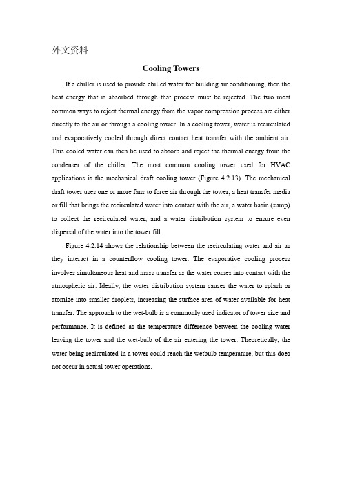
外文资料Cooling TowersIf a chiller is used to provide chilled water for building air conditioning, then the heat energy that is absorbed through that process must be rejected. The two most common ways to reject thermal energy from the vapor compression process are either directly to the air or through a cooling tower. In a cooling tower, water is recirculated and evaporatively cooled through direct contact heat transfer with the ambient air. This cooled water can then be used to absorb and reject the thermal energy from the condenser of the chiller. The most common cooling tower used for HVAC applications is the mechanical draft cooling tower (Figure 4.2.13). The mechanical draft tower uses one or more fans to force air through the tower, a heat transfer media or fill that brings the recirculated water into contact with the air, a water basin (sump) to collect the recirculated water, and a water distribution system to ensure even dispersal of the water into the tower fill.Figure 4.2.14 shows the relationship between the recirculating water and air as they interact in a counterflow cooling tower. The evaporative cooling process involves simultaneous heat and mass transfer as the water comes into contact with the atmospheric air. Ideally, the water distribution system causes the water to splash or atomize into smaller droplets, increasing the surface area of water available for heat transfer. The approach to the wet-bulb is a commonly used indicator of tower size and performance. It is defined as the temperature difference between the cooling water leaving the tower and the wet-bulb of the air entering the tower. Theoretically, the water being recirculated in a tower could reach the wetbulb temperature, but this does not occur in actual tower operations.FIGURE 4.2.14 Air/water temperature relationship in a counterflow cooling tower.The range for a chiller/tower combination is determined by the condenser thermal load and the cooling water flow rate, not by the capacity of the cooling tower. The range is defined as the temperature difference between the water entering the cooling tower and that leaving. The driver of tower performance is the ambient wet-bulb temperature. The lower the average wet-bulb temperature, the ―easier‖ it is for the tower to attain the desired range, typically 6°C (10°F) for HVAC applications. Thus, in a hot, dry climate towers can be sized smaller than those in a hot and humid area for a given heat load.Cooling towers are widely used because they allow designers to avoid some common problems with rejection of heat from different processes. The primary advantage of the mechanical draft cooling tower is its ability to cool water to within 3–6°C (5–10°F) of the ambient wet-bulb temperature. This means more efficient operation of the connected chilling equipment because of improved (lower) head pressure operation which is a result of the lower condensing water temperatures supplied from the tower.Cooling Tower DesignsThe ASHRAE Systems and Equipment Handbook (1996) describes over 10 types of cooling tower designs.Three basic cooling tower designs are used for most common HVAC applications. Based upon air and water flow direction and location of the fans, these towers can be classified as counterflow induced draft, crossflow induced draft, and counterflow forced draft.One component common to all cooling towers is the heat transfer packing material, or fill, installed below the water distribution system and in the air path. Thetwo most common fills are splash and film.Splash fill tends to maximize the surface area of water available for heat transfer by forcing water to break apart into smaller droplets and remain entrained in the air stream for a longer time. Successive layers of staggered splash bars are arranged through which the water is directed. Film fill achieves this effect byforcing water to flow in thin layers over densely packed fill sheets that are arranged for vertical flow. Towers using film type fill are usually more compact for a given thermal load, an advantage if space for the tower site is limited. Splash fill is not as sensitive to air or water distribution problems and performs better where water quality is so poor that excessive deposits in the fill material are a problem.Counterflow Induced DraftAir in a counterflow induced draft cooling tower is drawn through the tower by a fan or fans located at the top of the tower. The air enters the tower at louvers in the base and then comes into contact with water that is distributed from basins at the top of the tower. Thus, the relative directions are counter (down for the water, up for the air) in this configuration. This arrangement is shown in Figure 4.2.15. In this configuration, the temperature of the water decreases as it falls down through the counterflowing air, and the air is heated and humidified. Droplets of water that might have been entrained in the air stream are caught at the drift eliminators and returned to the sump. Air and some carryover droplets are ejected through the fans and out the top of the tower. The water that has been cooled collects in the sump and is pumped back to the condenser.FIGURE 4.2.15 Counterflow induced draft cooling tower.Counterflow towers generally have better performance than crossflow types because of the even air distribution through the tower fill material. These towers also eject air at higher velocities which reduces problems with exhaust air recirculation into the tower. However, these towers are also somewhat taller than crossflow types and thus require more condenser pump head.Crossflow Induced DraftAs in the counterflow cooling tower, the fan in the crossflow tower is located at the top of the unit (Figure 4.2.16). Air enters the tower at side or end louvers and moves horizontally through the tower fill. Water is distributed from the top of the tower where it is directed into the fill and is cooled by direct contact heat transfer with the air in crossflow (air horizontal and water down). Water collected in the sump is pumped back to the chiller condenser. The increased airflow possible with the crossflow tower allows these towers to have a much lower overall height. This results in lower pump head required on the condenser water pump compared to the counterflow tower. The reduced height also increases the possibility of recirculating the exhaust air from the top of the tower back into the side or end air intakes which can reduce the tower’s effectiveness.Counterflow Forced DraftCounterflow forced draft cooling towers have the fan mounted at or near the bottom of the unit near the air intakes (Figure 4.2.17). As in the other towers, water is distributed down through the tower and its fill, and through direct contact with atmospheric air it is cooled. Thermal operation of this tower is similar to the counterflow induced draft cooling tower. Fan vibration is not as severe for this arrangement compared to induced draft towers. There is also some additional evaporative cooling benefit because the fan discharges air directly across the sump which further cools the water.There are some disadvantages to this tower. First, the air distribution through the fill is uneven, which reduces tower effectiveness. Second, there is risk of exhaust air recirculation because of the high suction velocity at the fan inlets, which can reduce tower effectiveness. These towers find applications in smalland medium-sized systems.MaterialsCooling towers operate in a continuously wet condition that requires construction materials to meet challenging criteria. Besides the wet conditions, recirculating water could have a high concentration of mineral salts due to the evaporation process. Cooling tower manufacturers build their units from a combination of materials that provide the best combination of corrosion resistance and cost. Wood is a traditional material used in cooling tower construction. Redwood or fir are often used and are usually pressure treated with preservative chemicals. Chemicals such as chromated copper arsenate or acid copper chromate help prevent decay due to fungi or destruction by termites.FIGURE 4.2.16 Crossflow induced draft cooling tower.FIGURE 4.2.17 Counterflow forced draft cooling tower.Galvanized steel is commonly used for small- to mid-sized cooling tower structures. Hardware is usually made of brass or bronze. Critical components, such asdrive shafts, hardware mounting points, etc., may be made from 302 or 304 stainless steel. Cast iron can be found in base castings, motor housings, and fan hubs. Metals coated with plastics are finding application for special components.Many manufacturers make extensive use of fiberglass-reinforced plastic (FRP) in their structure, pipe, fan blades, casing, inlet louvers, and connection components. Polyvinyl chloride (PVC) is used for fill media, drift eliminators, and louvers. Fill bars and flow orifices are commonly injection molded from polypropylene and acrylonitrile butadiene styrene (ABS).Concrete is normally used for the water basin or sump of field erected towers. Tiles or masonry are used in specialty towers when aesthetics are important.PerformanceRejection of the heat load produced at the chilling equipment is the primary goal of a cooling tower system. This heat rejection can be accomplished with an optimized system that minimizes the total compressor power requirements of the chiller and the tower loads such as the fans and condenser pumps. Several criteria must be determined before the designer can complete a thorough cooling tower analysis, including selection of tower range, water-to-air ratio, approach, fill type and configuration, and water distribution system. Table 4.2.6 lists some of the common design criteria and normally accepted ranges for cooling towers.Most common HVAC applications requiring a cooling tower will use an ―off the shelf‖ unit fro m a cooling tower manufacturer. Manufacturer representatives are usually well informed about their products and their proper application. After the project design process has produced the information called for in Table 4.2.6, it is time to contact one or more cooling tower representatives and seek their input on correct tower selection.Control Scheme with ChillersMost cooling towers are subject to large changes in load and ambient wet-bulb temperature during normal operations. For a typical cooling tower, the tower fan energy consumption is approximately 10% of the electric power used by the chiller compressor. The condenser pumps are about 2–5% of the compressor power.Controlling the capacity of a tower to supply adequately cooled water to the condenser while minimizing energy use is a desirable operational scheme. Probably the most common control scheme employed for towers serving an HVAC load is to maintain a fixed leaving water temperature, usually 27°C (80°F). Fan cycling is a common method to achieve this cooling tower control strategy and is applicable to multiunit and multicell tower installations. However, this control method does not minimize total energy consumed by the chiller/cooling tower system components.Lowering the condensing water tempe rature increases a chiller’s efficiency. As long as the evaporator temperature is constant, a reduced condenser temperature will yield a lower pressure difference between the evaporator and condenser and reduce the load on the compressor. However, it is important to recognize that the efficiency improvements initially gained through lower condenser temperatures are limited. Improved chiller efficiency may be offset by increased tower fan and pumping costs. Maintaining a constant approach at some minimum temperature is desirable as long as the condensing temperature does not fall below the chiller manufacturer’s recommendations.Since most modern towers use two- or three-speed fans, a near optimal control scheme can be developed as follows (Braun and Diderrich, 1990):• Tower fans should be sequenced to maintain a constant approach during part load operation to minimize chiller/cooling tower energy use.• The product of range and condensing water flow rate, or the heat energy rejected, should be used to determine the sequencing of the tower fans.• Develop a simple relationship between tower capacity and tower fan sequencing.De Saulles and Pearson (1997) found that savings for a setpoint control versus the near optimal control for a cooling tower were very similar. Their control scheme called for the tower to produce water at the lowest setpoint possible, but not less than the chiller manufacturer would allow, and to compare that operation to the savings obtained using near optimal control as described above. They found that the level of savings that could be achieved was dependent on the load profile and the method of optimization. Their simulations showed 2.5 to 6.5% energy savings for the singlesetpoint method while the near optimal control yielded savings of 3 to 8%. Use of variable speed fans would increase the savings only in most tower installations. It is more economical to operate multiple cooling tower fans at the same speed than to operate one at maximum before starting the next fan. Variable speed fans should be used when possible in cooling towers.The system designer should ensure that any newly installed cooling tower is tested according to ASME Standard PTC 23 (ASME 1986) or CTI Standard ATC-105. These field tests ensure that the tower is performing as designed and can meet the heat rejection requirements for the connected chiller or refrigeration load.Selection CriteriaThe criteria listed in Table 4.2.6 are usually known a priori by the designer. If not known explicitly, then commonly accepted values can be used. These criteria are used to determine the tower capacity needed to reject the heat load at design conditions. Other considerations besides the tower’s capacity include economics, servicing, environmental considerations, and aesthetics. Many of these factors are interrelated, but, if possible, they should all be evaluated when selecting a particular tower design.Because economics is an important part of the selection process, two methods are commonly used —life-cycle costing and payback analysis. These procedures compare equipment on the basis of owning, operation, and maintenance costs. Other criteria can also affect final selection of a cooling tower design: building codes, structural considerations, serviceability, availability of qualified service personnel, and operational flexibility for changing loads. In addition, noise from towers can become a sensitive environmental issue. If local building code sound limits are an issue, sound attenuators at the air intakes and the tower fan exit should be considered. Aesthetics can be a problem with modern architectural buildings or on sites with limited land space. Several tower manufacturers can erect custom units that can completely mask the cooling tower and its operation.Applications[1]Unlike chillers, pumps, and air handlers, the cooling tower must be installed in an open space with careful consideration of factors that might cause recirculation (recapture of a portion of warm and humid exhaust air by the same tower) or restrict air flow. A poor tower siting situation might lead to recirculation, a problem not restricted to wet cooling towers. Similar recirculation can occur with air-cooled condensing equipment as well. With cooling tower recirculation, performance is adversely affected by the increase in entering wet-bulb temperature. The primary causes of recirculation are poor siting of the tower adjacent to structures, inadequate exhaust air velocity, or insufficient separation between the exhaust and intake of the tower.Multiple tower installations are susceptible to interference — when the exhaust air from one tower is drawn into a tower located downwind. Symptoms similar to the recirculation phenomenon then plague the downwind tower. For recirculation, interference, or physically blocking air-flow to the tower the result is larger approach and range which contribute to higher condensing pressure at the chiller. Both recirculation and interference can be avoided through careful planning and layout.Another important consideration when siting a cooling tower installation is the effect of fogging, or plume, and carryover. Fogging occurs during cooler weather when moist warm air ejected from the tower comes into contact with the cold ambient air, condenses, and forms fog. Fog from cooling towers can limit visibility and can be an architectural nuisance. Carryover is when small droplets of entrained water in the air stream are not caught by the drift eliminators and are ejected in the exhaust air stream. These droplets then precipitate out from the exhaust air and fall to the ground like a light mist or rain (in extreme cases). Carryover or drift contains minerals and chemicals from the water treatment in the tower and can cause staining or discoloration of the surfaces it settles upon. To mitigate problems with fog or[1]节选自James B. Bradford et al. ―HVAC Equipment and Systems‖.Handbook of Heating, Ventilation, and Air-Conditioning.Ed. Jan F. Kreider.Boca Raton, CRC Press LLC. 2001carryover, as with recirculation, the designer should consider nearby traffic patterns, parking areas, prevailing wind direction, large glass areas, or other architectural considerations.Operation and Maintenance Winter OperationIf chillers or refrigeration equipment are being used in cold weather, freeze protection should be considered to avoid formation of ice on or in the cooling tower. Capacity control is one method that can be used to control water temperature in the tower and its components. Electric immersion heaters are usually installed in the tower sump to provide additional freeze protection. Since icing of the air intakes can be especially detrimental to tower performance, the fans can be reversed to de-ice these areas. If the fans are operating in extremely cold weather, ice can accumulate on the leading edges of the fan blades, which can cause serious imbalance in the fan system. Instrumentation to detect out-of-limits vibration or eccentricity in rotational loads should be installed. As with any operational equipment, frequent visual inspections during extreme weather are recommended.Water TreatmentThe water circulating in a cooling tower must be at an adequate quality level to help maintain tower effectiveness and prevent maintenance problems from occurring. Impurities and dissolved solids are concentrated in tower water because of the continuous evaporation process as the water is circulated through the tower. Dirt, dust, and gases can also find their way into the tower water and either become entrained in the circulating water or settle into the tower sump. To reduce the concentration of these contaminants, a percentage of the circulating water is drained or blown-down. In smaller evaporatively cooled systems, this process is called a bleed-off and is continuous. Blow-down is usually 0.8 to 1.2% of the total water circulation rate and helps to maintain reduced impurity concentrations and to control scale formation. If the tower is served with very poor water quality, additional chemical treatments might be needed to inhibit corrosion, control biological growth, and limit the collection of silt. If the tower installation presents continuing water quality problems, a water treatment specialist should be consulted.LegionellosisLegionellosis has been connected with evaporative condensers, cooling towers, and other building hydronic components. Researchers have found that well-maintained towers with good water quality control were not usually associated with contamination by Legionella pneumophila bacteria. In a position paper concerning Legionellosis, the Cooling Tower Institute (CTI, 1996) stated that cooling towers are prone to colonization by Legionella and have the potential to create and distribute aerosol droplets. Optimum growth of the bacteria was found to be at about 37°C (99°F) which is an easily attained temperature in a cooling tower.The CTI proposed recommendations regarding cooling tower design and operation to minimize the presence of Legionella. They do not recommend frequent or routine testing for Legionella pneumophila bacteria because there is difficulty interpreting test results. A clean tower can quickly be reinfected, and a contaminated tower does not mean an outbreak of the disease will occur.MaintenanceThe cooling tower manufacturer usually provides operating and maintenance (O&M) manuals with a new tower installation. These manuals should include a complete list of all parts used and replaceable in the tower and also details on the routine maintenance required for the cooling tower. At a minimum, the following should also be included as part of the maintenance program for a cooling tower installation.• Periodic inspection of the entire unit to ensure it is in good repair.• Complete periodi c draining and cleaning of all wetted surfaces in the tower. This gives the opportunity to remove accumulations of dirt, slime, scale, and areas where algae or bacteria might develop.• Periodic water treatment for biological and corrosion control.• Conti nuous documentation on operation and maintenance of the tower. This develops the baseline for future O&M decisions and is very important for a proper maintenance policy.4.2.4 Packaged EquipmentCentral HVAC systems are not always the best application for a particular cooling or heating load. Initial costs for central systems are usually much higher than unitary or packaged systems. There may also be physical constraints on the size of the mechanical components that can be installed in the building. Unitary or packaged systems come factory assembled and provide only cooling or combined heating and cooling. These systems are manufactured in a variety of configurations that allow the designer to meet almost any application. Cabinet or skid-mounted for easy installation, typical units generally consist of an evaporator, blower, compressor, condenser, and, if a combined system, a heating section. The capacities of the units ranges from approximately 5 kW to 460 kW (1.5 to 130 tons). Typical unitary systems are single-packaged units (window units, rooftop units), split-system packaged units, heat pump systems, and water source heat pump systems. Unitary systems do not last as long (only 8 to 15 years) as central HVAC equipment and are often less efficient.Unitary systems find application in buildings up to eight stories in height, but they are more generally used in one-, two-, or three-story buildings that have smaller cooling loads. They are most often used for retail spaces, small office buildings, andclassrooms. Unitary equipment is available only in preestablished capacity increments with set performance characteristics, such as total L/s (cfm) delivered by the unit’s air handler. Some designers combine central HVAC systems with packaged equipment used on perimeter building zones. This composite can solve humidity and space temperature requirements better than packaged units alone. This also works well in buildings where it is impractical for packaged units to serve interior spaces.Table 4.2.7 lists some of the advantages and disadvantages of packaged and unitary HVAC equipment.Table 4.2.8 lists energy efficiency ratings (EERs) for typical electric air- and water-cooled split and single package units with capacity greater than 19 kW (65,000 Btuh).Typically, commercial buildings use unitary systems with cooling capacities greater than 18 kW (5 tons). In some cases, however, due to space requirements, physical limitations, or small additions, residential-sized unitary systems are used. If a unitary system is 10 years or older, energy savings can be achieved by replacing unitary systems with properly sized, energy-efficient models.a Electric air- and water-cooled split system and single package units with capacity over 19 kW(65,000 Btuh) are covered here.b EER, or energy efficiency ratio, is the cooling capacity in kW (Btu/h) of the unit divided by its electrical input (in watts) at standard (ARI) conditions of 35°C (95°F) for air-cooled equipment, and 29°C (85°F) entering water for water-cooled models.c Based on ARI 210/240 test procedure.d SEER (seasonal energy efficiency ratio) is the total cooling output kW (Btu) provided by the unitduring its normal annual usage period for cooling divided by the total energy input (in Wh)during the same period.e Split system and single package units with total capacity under 19 kW (65,000 Btuh) are covered here. This analysis excludes window units and packaged terminal units.FIGURE 4.2.18 Comparison between TXV and short-tube orifice systems capacity for a range of charging conditions and 95°F (35°C) outdoor temperature. (From Rodriquez et al., 1996).As with any HVAC equipment, proper maintenance and operation will ensure optimum performance and life for a system. Split-system air conditioners and heat pumps are the most common units applied in residential and small commercial applications. These units are typically shipped to the construction site as separate components; after the condenser (outdoor unit) and the evaporator (indoor unit) are mounted, the refrigerant piping is connected between them. The air conditioning technician must ensure that the unit is properly charged with refrigerant and check for proper operation. If the system is under- or overcharged, performance can be adversely affected. Rodriquez et al. (1996) found that performance of an air conditioning system equipped with a short tube orifice was affected by improper charge (Figure 4.2.18).The plot in Figure 4.2.18 clearly shows that for a 20% under-charge in refrigerant, a unit with a short tube orifice suffers a 30% decrease in cooling capacity. This same study also investigated the effects of return-air leakage. A common problem with new installations is improper sealing of duct connections at the diffusers and grills as well as around the return-air plenum. Leakage amounts as low as 5% in the return air ducts resulted in capacity and efficiency reductions of almost 20% for high humidity climates. These reductions dropped to about 7% for low humidity climates. The results of the charging and leakage studies suggest the need for the installation contractor, maintenance contractor, and system owner to ensure the proper installation of the air conditioning system.FIGURE 4.2.19 Rooftop packaged heating and air conditioning unit. (Adapted from CarrierCorporation).Packaged UnitsPackaged units are complete HVAC units that are usually mounted on the exterior of a structure (roof or wall) freeing up valuable indoor floor space (Figure 4.2.19). They can also be installed on a concrete housekeeping pad at ground level. Because they are self-contained, complete manufactured units, installation costs are usually lower than for a site-built HVAC system.Single-package units consist of a blower section, filter bank, evaporator coil, at least one compressor (larger units may have more than one), and an air-cooled condensing section. Units may also come equipped with a heating section. Heating isaccomplished using either natural gas or electricity. Heat pump systems can be used in situations where electricity is the only source of energy. Unitary heat pumps are restricted in size to no more than 70 kW (20 tons).As packaged units age and deteriorate, their efficiency often decreases while the need for maintenance increases. Upgrading existing packaged units to high-efficiency models will result in substantial longterm energy savings. In the last 10 to 15 years, manufacturers have made significant improvements in the efficiency of packaged units. The efficiency of energy transfer at both the evaporator and condenser coils has been improved, high-efficiency motors are now standard, and blower and compressor designs have improved in high-efficiency packaged units. Scroll compressors are now commonplace on mediumsized (70 to 210 kW; 20 to 60 ton) rooftop units. Energy efficiencies of newer units have a SEER in the range of 9.50 to 13.0. It is not uncommon to find older units operating at efficiencies as low as 6.0, and most operate at less than 9.0. Gas-fired heating sections typically have an annual fuel utilization efficiency(AFUE) of about 80%. All newer packaged rooftop units are equipped with factory-installed microprocessor controls. These controls make maintaining equipment easier and improve energy efficiency of both the unit and the overall HVAC system. Control features include temperature setback and on/off scheduling. Larger systems can be delivered with variable air volume capability. Also, most units have an optional communication interface for connection to an energy management control system.Vertical Packaged UnitsVertical packaged units are typically designed for indoor or through-the-wall installation. These units are applied in hotels and apartments. Some designs have a water-cooled condenser, which can be fed from a cooling tower and/or city water. Many others use standard air-cooled condensers. Both style units have all other components mounted inside the package. Ductwork, if needed, can be connected to the unit to distribute the air.。
翻译原文
Department of Mechanical Engineering, Federal University of Technology, Owerri 2 Department of Mechanical Engineering, University of Port Harcourt (NIGERIA) *Corresponding author: ucheremy@.
A typical centralized HVAC system comprises of condenser water loop, together with chillers, indoor air loops and chilled water loop to provide comfort environment for the conditioned space (Stoecker, 1975). The process of a condenser water loop consists of condenser, condenser water piping and pumps, and cooling towers. Condensers transfer indoor cooling load and heat generated by compressors into condenser water pipe where condenser water pumps provide the energy to overcome the friction loss and deliver condenser water to cooling towers. Cooling towers reject heat to the environment through heat and mass transfer to the ambient air. The control and optimization has been considered as one of the most difficult problems for practice control engineers (Ahn and Mitchell, 2001). Condenser water loop is one of the five main function loops and its operation has significant effect to the overall system performance. The main issues for efficient operation of condenser water loop are the performance of cooling towers as well as the interactions between cooling towers (Soylemez, 2001), condenser water pumps and chillers. For cooling towers, Cassidy and Stack’s work (1988) showed that varying the speed of cooling tower fans is a good way to reduce energy consumption. Braun and Doderich (1990) proposed Near-optimal control of cooling towers based on parameter estimated from design data. This method was further adopted by Cascia (1999) to simplify the component model and provide equations for determining the set points of near-optimal control. For interactions between chillers and cooling towers, Shelton and Joyce (2001) showed in their work that 1.5gpm/Ton condenser water flow rate as an optimal solution. Later, Kirsner (1996) pointed out that high condenser water flow rate, 3 gpm/Ton, has good performance at full load condition, while low condenser water flow rate, 1.5gpm/Ton, has advantages at part load conditions. Michael and Emery (1994) analyzed the costoptimal selection of the cooling tower range and approach and provided the design information for hermetic centrifugal and reciprocating chillers. Schwedler (1998) studied the variation of condenser water supply temperature and used several examples to demonstrate his main idea that the lowest possible leaving tower water temperature does not always conserve system energy. However, his research only considered the fans with halfspeed and full-speed conditions, which was not conclusive. Lu and Cai (2006) work showed that the optimum operation of the water loop condenser has a strong relation with the operating range of the cooling tower; the wet-bulb temperature, Twb; and condenser water supply temperature, Tcws; and the interaction between chillers and cooling towers. It was established that the optimal operating range of a cooling towers lied in the portion where heat rejection rate of the cooling tower increases with either the increased airflow rate or increased water flow rate, and vice versa. Also, if the airflow rate is kept at 13 o kg/s at 25 C wet-bulb temperature instead of 9 kg/s, the power consumption of fan and pump is 6.11kW. Compared with power consumption of 5.26 kW at 9 kg/s at optimal point, almost 17% energy can be saved when the ambient o o wet-bulb temperature is changed from 25 C to 30 C. This implies that the optimal operating points are different for the same heat rejection rate under different wet-bulb temperature. In spite of the progress made in recent years on individual component modeling, control, optimization and operation rules, there is still lack of systematic approach which consider the condenser water loop as a system, to optimize its operation. Therefore, this paper presents a novel real time optimization strategy for condenser water loop. By considering characteristics of cooling towers, effects of different ambient environment, interactions between chillers and cooling towers, the energy efficiency of the condenser water loop can be formulated as a standard optimization problem. The total energy cost can be minimized by optimizing set points of manipulated variables, such as the flow rate of condenser water, airflow rate in cooling towers and condenser water supply temperature. The GA consists of binary-coded string population and four basic operators: selection, crossover, mutation and mating are used to search the optimal solutions. This method is suitable to deal with both single chiller and multi-chiller central parts and has potential to substantially reduce the operating cost.
直接空冷凝汽器换热性能影响因素研究

48机械设计与制造Machinery Design&Manufacture第3期2021年3月直接空冷凝汽器换热性能影响因素研究刘晓玲\张力、王智2(1.山东电力工程咨询院有限公司,山东济南250013;2.华北电力大学电站设备状态监测与控制教育部重点实验室,河北保定071003)摘要:以内蒙古某电厂为研究对象,采用理论计算和数值模拟相结合的方法,研究了环境温度、风速、湿度及风机转速对直接空冷凝汽器换热特性的影响。
研究表明:来流风速为(13~15)m/s时,总换热量较设计工况降低了(3.2~7.5)%;环境温度对总换热量影响很大,但当环境温度大于15T时,总换热量下降趋势逐渐变的缓慢;环境湿度对总换热量的影响较小;随着环境风速的增加,各空冷单元风机进口流量整体呈下降趋势,其中迎风侧的第一个风机进口流量降幅最大。
关键词:来流风速;环境温度;凝汽器渣接空冷;换热特性中图分类号:T H16;T K26文献标识码:A文章编号:1001-3997(2021 )03-0048-05Study on Influencing Factors of Heat Transfer Performanceof Direct Air-Cooled CondenserLIU Xiao-ling', ZHANG Li1, WANG Zhi2(1.Shandong Electric Power Engineering Consulting Institute Corp.,Ltd.,Shandong Jinan250013, C hina;2.Key Lab of Condition Monitoring and Control for Power Plant Equipm ent,North China Electric Power University,Ministry of Education,Hebei Baoding071003, C h in a)Abstract:TaA: m g a power plant in Inner Mongolia as the research object, the effects o f e nvironmental temperature, w ind speed, humidity and f a n speed on the heat transfer characteristics o f d irect air-cooled condenser were studied by combining theoretical calculation with numerical simulalion. The results show that the total heat transfer decreases by(3.2~7.5)% compared with the design condition when the inflow wind speed is (A3~\5)m/&EnvironmentaI temperature has a great influence on the total he —at transfer^ but when the ambient temperature is higher than15T1, the total heat transfer decreases slowly. The influence o f ambient humidity on total heat transfer is small. With the increase o f ambient wind speedy the inlet flow rote o f each aircooled unit fa n decreases as a whole,and the first fa n on the windward side decreases the most.Key Words: Inlet Air Velocity;Environmental Temperature;Condenser;Direct Air Cooling;Heat Transfer Characteristicsl引言中国是一个严重缺水的国家,根据电力发展“十三五”规划,煤电机组的超低排放及节能改造成为煤电清洁化发展的重点% 随着600M W、1OOOMW机组相继采用直接空冷技术,标志着我国 空冷技术已经达到世界领先水平。
SK120、SK200、SK350系列纯正三角波换流器用户手册说明书
SK120,SK200,SK350 Series Pure Sine Wave InverterUser’s ManualTable of contents1. Important Safety Information.……………………………………………… 1-1 General Safety Precautions……………………………………………1-2Precautions When Working with Batteries……….…………………..2. Features………………………………………………………………………... 2-1 Electrical Performance………………………………………………… 2-2 Mechanical Drawing of Socket Type(Power Claw PP75)… …..….2-3Mechanical Drawing of Strip Wire Type……………….…………….3. Instructions………………………………………………….………………… 3-1 Front Panel Operation..………………………………………………...3-2Rear Panel Operation..…………………………………………………3-3 Protections Features……..……………………………………………. 3-4 Installation.………………………………………………….…………...3-5Making DC Wiring Connections……...………………………………..3-6 AC Safety Grounding…………………………………………………... 3-7 Inverter Operation……………………………………………………… 4. Troubleshooting guide……………………………………………………… 5. Maintenance……………………………………………………………………6. Warranty………………………………………………………………………..D Copyright :This manual is the copyright of COTEK Electronic lnd. Co., Ltd. Be not allowed to reproduc or copywithout permission of the owner.1. Important Safety Information1-1. General Safety Precautions1-1-1. Do not expose the Inverter to rain, snow, spray, bilge or dust.To reduce risk of hazard, do not cover or obstruct the ventilationopenings. Do not install the Inverter in a zero-clearance compartment.Over heating may result.1-1-2. To avoid a risk of fire and electronic shock. Make sure that existing wiring is in good electrical condition; and that wire size is notundersized.Do not operate the Inverter with damaged or substandard Wiring.1-1-3. This equipment contains components which can produce arcs or sparks. To prevent fire or explosion do not install in compartmentscontaining batteries or Flammable materials or in locations whichrequire ignition protected equipment. This includes any spacecontaining gasoline-powered machinery, fuel tanks, or joints, fittings,or other connection between components of the fuel system.1-2. Precautions When Working with Batteries1-2-1. If battery acid contacts skin or clothing, wash immediately with soap and water. If acid enters eye, immediately flood eye with runningcold water for at least 20 minutes and get medical attentionimmediately.1-2-2. Never smoke or allow a spark or flame in vicinity of battery or engine.1-2-3. Do not drop a metal tool on the battery. The resulting spark orshort-circuit on the battery of other electrical part may cause anexplosion.1-2-4. Remove personal metal items such as rings, bracelets, necklaces, and watches when working with a lead-acid battery,A lead-acid battery produces a short-circuit current high enough toweld a ring or the like to metal, causing a severe burn.2. FeaturesPure sine wave output (THD < 3%)Output frequency:50 / 60Hz switch selectionsInput & output completely isolated designHigh efficiency 84~94%Capable of driving inductive & capacitive loads at the start moment.A LED Indicator with twin color displays all operation status.Loading and temperature controlled cooling fan.Built in advanced microprocessor to make friendly interface with user.Protection:Input low voltage Overload Short circuit Low battery alarm Input over voltage Over temperature2-1. Electrical PerformanceItem SK120-112SK120-124SK120-148SK120-212 SK120-224 SK120-248 Continuous Output Power 120WMaximum Output Power 132WSurge Rating (Max) 240WInput voltage 12Vdc 24Vdc 48Vdc 12Vdc 24Vdc 48Vdc Output Voltage 100 / 110 / 120Vac +/- 5% 220 / 230 / 240Vac +/- 3%Frequency(Switch Selections)50 / 60Hz +/- 0.05%Output Waveform Pure Sine Wave ( THD < 3% ) Efficiency (full load) Max *1 89% 91% 93% 92% 93% 94%Input Voltage Regulation 10.5-15VDC21.0-30VDC42-60VDC10.5-15VDC21.0-30VDC42-60VDCFailure Indicator Red LEDProtectionOverload (Shut down),Short Circuit (Shut down),Reverse Polarity (Fuse), Over / Under Input Voltage (Auto recovery), Over Temperature (Auto recovery).Remote Control Yes (ON / OFF mode controlled by hard wire) See 3-2 Safety Meet UL458 EN60950-1EMC FCC Class A EN55022:1997EN61000-3-2:1998EN61000-3-3:1995EN55024:2001e-marke13 023495Operating Temperature Range 0 - 40 ℃Storage Temperature Range -30℃ to 70℃Cooling convection coolingDimensions 185(L)x147(W)x60(H)mm / 7.3(L)x5.8(W)x2.36(H) Inch Weight 1kgNote: The specifications are subject to change without notice.Item SK200-112SK200-124SK200-148SK200-212 SK200-224 SK200-248 Continuous Output Power 200WMaximum Output Power 220WSurge Rating (Max) 400WInput voltage 12Vdc 24Vdc 48Vdc 12Vdc 24Vdc 48Vdc Output Voltage 100 / 110 / 120Vac +/- 5% 220 / 230 / 240Vac +/- 3%Frequency(Switch Selections)50 / 60Hz +/- 0.05%Output Waveform Pure Sine Wave ( THD < 3% )Efficiency (full load) Max *187% 90% 92% 90% 93% 94%Input Voltage Regulation 10.5-15VDC21.0-30VDC42-60VDC10.5-15VDC21.0-30VDC42-60VDCFailure Indicator Red LEDProtectionOverload (Shut down),Short Circuit (Shut down),Reverse Polarity (Fuse), Over / Under Input Voltage (Auto recovery), Over Temperature (Auto recovery).Remote Control Yes (ON / OFF mode controlled by hard wire) See 3-2 Safety Meet UL458 EN60950-1EMC FCC Class A EN55022:1997EN61000-3-2:1998EN61000-3-3:1995EN55024:2001e-marke13 023496Operating Temperature Range 0 - 40 ℃Storage Temperature Range -30℃ to 70℃Cooling FAN (Controlled by load and temperature)Dimensions 185 (L) x 147 (W) x 60 (H) mm / 7.3 (L) x 5.8 (W) x 2.36 (H) Inch Weight 1.2kgNote: The specifications are subject to change without notice.Item SK350-112SK350-124SK350-148SK350-212 SK350-224 SK350-248 Continuous Output Power 350WMaximum Output Power 385WSurge Rating (Max) 700WInput voltage 12Vdc 24Vdc 48Vdc 12Vdc 24Vdc 48Vdc Output Voltage 100 / 110 / 120Vac +/- 5% 220 / 230 / 240Vac +/- 3%Frequency(Switch Selections)50 / 60Hz +/- 0.05%Output Waveform Pure Sine Wave ( THD < 3% )Efficiency (full load) Max *184% 86% 88% 86% 89% 90%Input Voltage Regulation 10.5-15VDC21.0-30VDC42-60VDC10.5-15VDC21.0-30VDC42-60VDCFailure Indicator Red LEDProtectionOverload (Shut down),Short Circuit (Shut down),Reverse Polarity (Fuse), Over / Under Input Voltage (Auto recovery), Over Temperature (Auto recovery).Remote Control Yes (ON / OFF mode controlled by hard wire) See 3-2 Safety Meet UL458 EN60950-1EMC FCC Class A EN55022:1997EN61000-3-2:1998EN61000-3-3:1995EN55024:2001e-marke13 023497Operating Temperature Range 0 - 40 ℃Storage Temperature Range -30℃ to 70℃Cooling FAN (Controlled by load and temperature)Dimensions 185(L)x147(W)x60(H)mm / 7.3(L)x5.8(W)x2.36(H) Inch Weight 1.4kgNote: The specifications are subject to change without notice.2-2. Mechanical Drawing of Socket (Power Claw PP75)2-3. Mechanical Drawing of Strip Wire Type3. InstructionsThis power inverter series is a the member of the most advanced line of mobile AC power systems available.To get the most out of the power inverter, it must be installed and used properly.Please read the instructions in this manual before installation and operation this model.3-1. Front Panel Operation:3-1-1. Front view:POWERSTATUS50HzFREQ.60HzAC OUTPUTPURE SINE WAVE INVERTERPURE SINEWAVE INVERTERAC OUTPUT60Hz50Hz FREQ.POWERSTATUS3-1-2. AC Frequency:Selected by Dip Switch50 HZ ON60 HZ OFF3-1-3. Status:Display Power & Fault Status3-1-4. AC Output (available Sockets):3-1-5. DC Input (available type):3-2. Rear Panel Operation :3-2-1. ON / OFF / REMOTE Main Switch.3-2-1-1. Before installing the inverter, make sure the main switch mustbe “OFF”. 3-2-1-2. Before using the remote unit, make sure the main switch mustbe “ REMOTE”. 3-2-1-3. Ensure the remote control contact is off.3-2-1-4. Remote Port :Place 0.75mm 2 and Screw type cable betweenthe remote port and the panel.3-2-1-5. Remote port ON/OFF inverter setup statusVCEO > VBATMODE Ⅱ MODE ⅠNOTE: Only one of control mode can be presented. When operating. 3-2-2. DC Input Terminals :Connect to 12V / 24V / 48V battery or the other power sources. 【+】is positive,【-】is negative. Reverse polarity connection will blow internal fuse and may damage inverter permanently.DC Input Voltage MinimumMaximum 12 V 10.5 15.0 24 V 21.0 30.0 48 V42.060.03-2-3. Chassis Ground: using # 8 AWG wire to connect vehicle chassis.MODE ⅢMODE Ⅳ3-3. Protections Features:12 V 16V 13V11.0V <10.5V12.524 V 32V 26V22.0V <21.0V25.055℃ 45℃48V 62V 52V44.0V <42.0V50.0Note: The specifications are subject to change without notice.3-4. Installation:Where to install. The power inverter should be installed in a location thatMeets the following requirements:3-4-1. Dry – Do not allow water to drip or splash on the inverter.3-4-2. Cool – Ambient air temperature should be between 0℃ and 40℃, the cooler the better.3-4-3. Safe – Do not install in a battery compartment or other areas where flammable fumes may exist, such as fuel storage areas or enginecompartments.3-4-4. Ventilated – Allow at least one inch of clearance around the inverter for air flow. Ensure the ventilation openings on the rear and frontof the unit are not obstructed.3-4-5. Dust – Do not install the Inverter in a dusty environmentswhere are dust, wood particles or other filings/shavings are present.These dust can be pulled into the unit when the cooling fan isoperating.3-4-6. Close to batteries – Avoid excessive cable lengths but do not install the Inverter in the same compartment as batteries.Use the recommended wire lengths and sizes (see section 3-5).Also do not mount the Inverter where it will be exposed to thegases produced by the battery.These gases are very corrosive and prolonged exposure also willdamage the Inverter.3-5. Making DC Wiring Connections:Follow this procedure to connect the battery cables to the DC input terminals of the Inverter. Your cables should be as short as possible (Ideally,less than 6 feet / 1.8 meters ) enough to handle the required current inaccordance with the electrical codes or regulations application. Cables are not an adequate gauge (too narrow) or too long will decrease the inverterperformances such as poor surge capability and low input voltage warnings frequently and shutdowns. UVP warning presents due to DC voltage drop across the cables from the inverter to the batteries.The longer or narrower the cables, the greater the voltage drop.Increasing your DC cable size will help improve the situation.Following cable recommendations for the best performance of inverter.(Apply both 120V and 230V versions )3-6. AC Safety Grounding:The AC output ground wire should go to the grounding point for your loads ( for example, a distribution panel ground bus ).3-6-1. Neutral Grounding (GFCI’S):3-6-1-1. 120V models:The neutral conductor of the AC output circuit of the Inverter is automatically connected to the safetyground during inverter operation. In accordance with theNational Electrical Code requirements that separately derivedAC sources (such as inverter and generators) have theirneutral conductors tied to ground in the same way that theneutral conductor from the utility is tied to ground at the ACbreaker panel. For models configured with a transfer relay,while AC utility power is presenting and the Inverter is inbypass mode, this connection (neutral of the Inverter’s ACoutput to input safety ground) is not present so that the utilityneutral is only connected to ground at your breaker panel,as required.3-6-1-2. 230V models:There is no connection made inverter interiorbetween either the line or neutral conductor to the safetyground.Ground Fault Circuit Interrupters (GFCI):Installations in Recreational Vehicles (for North American approvals) willrequire GFCI protection of all branch circuit connected to the AC output ofthe hardwire terminal equipped Inverter. In addition, electrical codesrequire GFCI protection of certain receptacles in residential installations.While the pure sine wave output of the Inverter is equivalent to thewaveform provided by utilities, compliance with UL standards requires us to test and recommend specific GFCI.Cotek has tested the following GFCI – protected 20A receptacles and found that they functioned properly when connected to the output of the Inverter.3-7. Inverter Operation:To operate the power inverter, turn the main switch ON. The power inverter is now ready to deliver AC power to your loads. If there is several loads use, turn them on separately after the inverter has been “ON” in order to prevent the OVP present caused by the surge power.3-7-1. Set the power switch to the “ON” position and the buzzer will send out “Beep” sounds at the moment the inverter will do self-diagnosis,then the Power Status LED indicators will also appear various colors.Finally the buzzer will sound another “Beep” and the Power StatusLED indicators will turn to “Green” color, the inverter starts workingsuccessfully.3-7-2. Set the power switch to the OFF position, the inverter stops and all the lights that are On, go Off.3-7-3. Set power inverter switch to the ON position and turn the test load On. The inverter should supply power to the load. If you plan toaccurately measure the true output r.m.s. voltage of inverter, a metersuch ad FLUKE 45 BECKMAN 4410 or TRIPLETT 4200 must beused.4. Troubleshooting guide:Problems and Symptoms Possible Cause Solutions “No AC Power Output”STATUS illuminates the red LEDa. Blinking fast Over input voltage.( OVP ) Check input voltage. Reduce input voltage.b. Blinking slow. Low input voltage.( UVP ) Recharge battery. Check connections and cable.c. Blinking Intermittently. Thermal shutdown.( OTP ) Improve ventilation. Make sure ventilation openings in inverter are not obstructed. Reduce ambient temperature.d. Solid ON. Short circuit or Wiringerror.Overload.(OLP) Check AC wiring for short circuit. Reduce load.5. Maintenance:Very little maintenance is required to keep your inverter operating properly.You should clean the exterior of the unit periodically with a damp cloth toprevent accumulation of dust and dirt.At the same time, tighten the screws on the DC input terminals.6. Warranty:We warrant this product against defects in materials and workmanship for a period of 24 months from the date of purchase and will repair or replace any defective Power Inverter when directly returned, postage paid, to us.This warranty will be considered void if the unit has suffered any obviousphysical damage or alteration either internally or externally and does notcover damage arising from improper use such as plugging.The unit into an unsuitable power sources attempts to operate products with excessive power consumption requirements, or use in unsuitable environments.This is the only warranty that the company makes.No other warranties express or imply including warranties of merchantability and fitness for a particular purpose.Repair and replacement are your sole remedies and the company shall not be liable for damages, whether direct, incidental, special or consequential, even though caused by negligence or other fault.。
ASHRAE系统和设备冷却塔ASHRAE-Systems-and-Equipment-Cooling-Towers
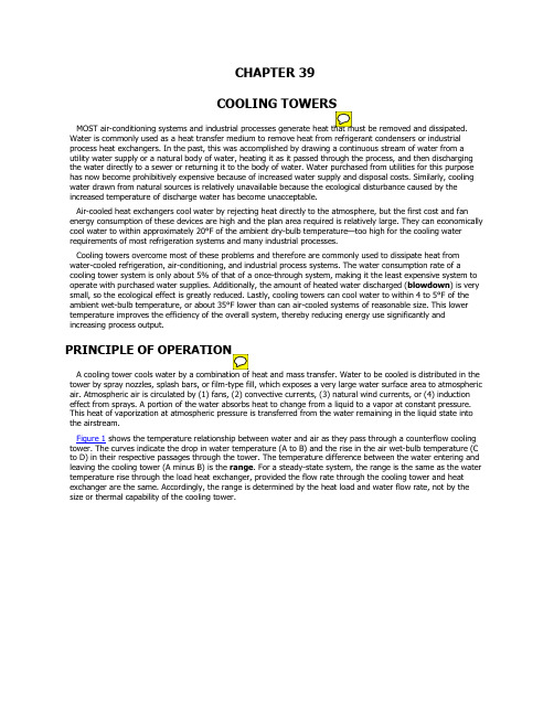
CHAPTER 39Air-cooled heat exchangers cool water by rejecting heat directly to the atmosphere, but the first cost and fan energy consumption of these devices are high and the plan area required is relatively large. They can economically cool water to within approximately 20°F of the ambient dry-bulb temperature—too high for the cooling waterrequirements of most refrigeration systems and many industrial processes.Cooling towers overcome most of these problems and therefore are commonly used to dissipate heat from water-cooled refrigeration, air-conditioning, and industrial process systems. The water consumption rate of a cooling tower system is only about 5% of that of a once-through system, making it the least expensive system to operate with purchased water supplies. Additionally, the amount of heated water discharged (blowdown) is very small, so the ecological effect is greatly reduced. Lastly, cooling towers can cool water to within 4 to 5°F of the ambient wet-bulb temperature, or about 35°F lower than can air-cooled systems of reasonable size. This lower temperature improves the efficiency of the overall system, thereby reducing energy use significantly and increasing process output.Figure 1 shows the temperature relationship between water and air as they pass through a counterflow cooling tower. The curves indicate the drop in water temperature (A to B) and the rise in the air wet-bulb temperature (C to D) in their respective passages through the tower. The temperature difference between the water entering and leaving the cooling tower (A minus B) is the range. For a steady-state system, the range is the same as the water temperature rise through the load heat exchanger, provided the flow rate through the cooling tower and heat exchanger are the same. Accordingly, the range is determined by the heat load and water flow rate, not by the size or thermal capability of the cooling tower.Thermal performance of a cooling tower depends principally on the entering air wet-bulb temperature. The entering air dry-bulb temperature and relative humidity, taken independently, have an insignificant effect on thermal performance of mechanical-draft cooling towers, but do affect the rate of water evaporation in the cooling tower. A psychrometric analysis of the air passing through a cooling tower illustrates this effect (Figure 2). Air enters at the ambient condition Point A, absorbs heat and mass (moisture) from the water, and exits at Point B in a saturated condition (at very light loads, the discharge air may not be fully saturated). The amount of heat transferred from the water to the air is proportional to the difference in enthalpy of the air between the entering and leaving conditions (h B–h A). Because lines of constant enthalpy correspond almost exactly to lines of constant wet-bulb temperature, the change in enthalpy of the air may be determined by the change in wet-bulbtemperature of the air.The ratio of latent to sensible heat is important in analyzing water usage of a cooling tower. Mass transfer(evaporation) occurs only in the latent portion of heat transfer and is proportional to the change in specific humidity. Because the entering air dry-bulb temperature or relative humidity affects the latent to sensible heattransfer ratio, it also affects the rate of evaporation. In Figure 2, the rate of evaporation in Case AB (W B–W A) is less than in Case DB (W B–W D) because the latent heat transfer (mass transfer) represents a smaller portion of the total.The evaporation rate at typical design conditions is approximately 1% of the water flow rate for each 12.5°F ofwater temperature range; however, the average evaporation rate over the operating season is less than the design rate because the sensible component of total heat transfer increases as entering air temperature decreases.In addition to water loss from evaporation, losses also occur because of liquid carryover into the dischargeairstream and blowdown to maintain acceptable water quality. Both of these factors are addressed later in this chapter.DESIGN CONDITIONSThe thermal capability of any cooling tower may be defined by the following parameters:Entering and leaving water temperaturesEntering air wet-bulb or entering air wet-bulb and dry-bulb temperaturesWater flow rateThe entering air dry-bulb temperature affects the amount of water evaporated from any evaporative cooling tower. It also affects airflow through hyperbolic towers and directly establishes thermal capability in any indirect-contact cooling tower component operating in a dry mode. Variations in tower performance associated with changes in the remaining parameters are covered in the section on Performance Curves.The thermal capability of a cooling tower used for air conditioning is often expressed in nominal cooling tower tons. A nominal cooling tower ton is defined as cooling 3 gpm of water from 95°F to 85°F at a 78°F entering air wet-bulb temperature. At these conditions, the cooling tower rejects 15,000 Btu/h per nominal cooling tower ton. The historical derivation of this 15,000 Btu/h cooling tower ton, as compared to the 12,000 Btu/h evaporator ton, is based on the assumption that at typical air-conditioning conditions, for every 12,000 Btu/h of heat picked up in the evaporator, the cooling tower must dissipate an additional 3000 Btu/h of compressor heat. For specific applications, however, nominal tonnage ratings are not used, and the thermal performance capability of the tower is usually expressed as a water flow rate at specific operating temperature conditions (entering water temperature, leaving water temperature, entering air wet-bulb temperature).TYPES OF COOLING TOWERSTwo basic types of evaporative cooling devices are used. The first of these, the direct-contact or open cooling tower (Figure 3), exposes water directly to the cooling atmosphere, thereby transferring the source heat load directly to the air. The second type, often called a closed-circuit cooling tower, involves indirect contact between heated fluid and atmosphere (Figure 4), essentially combining a heat exchanger and cooling tower into one relatively compact device.Figure 4. Indirect-Contact or Closed-Circuit Evaporative Cooling TowerFigure 5. Types of FillTo increase contact surfaces as well as time of exposure, a heat transfer medium, or fill, is installed below the water distribution system, in the path of the air. The two types of fill in use are splash-type and film-type (Figure 5). Splash-type fill maximizes contact area and time by forcing the water to cascade through successive elevations of splash bars arranged in staggered rows. Film-type fill achieves the same effect by causing the water to flow in a thin layer over closely spaced sheets, principally polyvinyl chloride (PVC), that are arranged vertically.Either type of fill can be used in counterflow and cross-flow towers. For thermal performance levels typically encountered in air conditioning and refrigeration, a tower with film-type fill is usually more compact. However, splash-type fill is less sensitive to initial air and water distribution and, along with specially configured, more widely spaced film-type fills, is preferred for applications that may be subjected to blockage by scale, silt, or biological fouling.Indirect-contact (closed-circuit) cooling towers contain two separate fluid circuits: (1) an external circuit, in which water is exposed to the atmosphere as it cascades over the tubes of a coil bundle, and (2) an internal circuit, in which the fluid to be cooled circulates inside the tubes of the coil bundle. In operation, heat flows from the internal fluid circuit, through the tube walls of the coil, to the external water circuit and then, by heat and mass transfer, to atmospheric air. As the internal fluid circuit never contacts the atmosphere, this unit can be used to cool fluids other than water and/or to prevent contamination of the primary cooling circuit with airborne dirt and impurities. Some closed-circuit cooling tower designs include cooling tower fill to augment heat exchange in the coil (Figure 6).Types of Direct-Contact Cooling TowersNon-Mechanical-Draft Towers. Aspirated by sprays or a differential in air density, these towers do not contain fill and do not use a mechanical air-moving device. The aspirating effect of the water spray, either vertical (Figure 7) or horizontal (Figure 8), induces airflow through the tower in a parallel flow pattern.Figure 7. Vertical Spray TowerFigure 8. Horizontal Spray TowerFigure 9. Hyperbolic TowerBecause air velocities for the vertical spray tower (both entering and leaving) are relatively low, such towersare susceptible to adverse wind effects and, therefore, are normally used to satisfy a low-cost requirement when operating temperatures are not critical to the system. Some horizontal spray towers (Figure 8) use high-pressure sprays to induce large air quantities and improve air/water contact. Multispeed or staged pumpingsystems are normally recommended to reduce energy use in periods of reduced load and ambient conditions.Figure 10. Conventional Mechanical-Draft Cooling TowersFigure 11. Factory-Assembled Counterflow Forced-Draft TowerPrimary justification of these high first-cost products comes through reduction in auxiliary power requirements (elimination of fan energy), reduced property area, and elimination of recirculation and/or vapor plume interference. Materials used in chimney construction have been primarily steel-reinforced concrete; early-day timber structures had size limitations.Mechanical-Draft Towers.Figure 10 shows five different designs for mechanical-draft (conventional) towers. Fans may be on the inlet air side (forced-draft) or the exit air side (induced-draft). The type of fan selected, either centrifugal or axial, depends on external pressure needs, permissible sound levels, and energy usage requirements. Water is downflow; the air may be upflow (counterflow heat transfer) or horizontal flow (cross-flow heat transfer). Air entry may be through one, two, three, or all four sides of the tower. All four combinations (i.e., forced-draft counterflow, induced-draft counterflow, forced-draft cross-flow, and induced-draft cross-flow) havebeen produced in various sizes and configurations.Towers are typically classified as either factory-assembled (Figure 11), where the entire tower or a few large components are factory-assembled and shipped to the site for installation, or field-erected (Figure 12), where the tower is constructed completely on site.Most factory-assembled towers are of metal construction, usually galvanized steel. Other constructions include stainless steel and fiberglass-reinforced plastic (FRP) towers and components. Field-erected towers are predominantly framed of preservative-treated Douglas fir or redwood, with FRP used for special components and casing materials. Environmental concerns about cutting timber and wood preservatives leaching into cooling tower water have led to an increased number of cooling towers having FRP structural framing. Field-erected towers may also be constructed of galvanized steel or stainless steel. Coated metals, primarily steel, are also used for complete towers or components. Concrete and ceramic materials are usually restricted to the largest towers (see the section on Materials of Construction).Special-purpose towers containing a conventional mechanical-draft unit in combination with an air-cooled (finned-tube) heat exchanger are wet/dry towers (Figure 13). They are used for either vapor plume reduction or water conservation. The hot, moist plumes discharged from cooling towers are especially dense in cooler weather. On some installations, limited abatement of these plumes is required to avoid restricted visibility on roadways, on bridges, and around buildings.A vapor plume abatement tower usually has a relatively small air-cooled component that tempers the leaving airstream to reduce the relative humidity and thereby minimize the fog-generating potential of the tower. Conversely, a water conservation tower usually requires a large air-cooled component to significantly reduce water consumption and provide plume abatement. Some designs can handle heat loads entirely by the nonevaporative air-cooled heat exchanger portion during reduced ambient temperature conditions.Figure 13. Combination Wet-Dry TowerFigure 14. Adiabatically Saturated Air-Cooled Heat ExchangerA variant of the wet/dry tower is an evaporatively precooled/ air-cooled heat exchanger. It uses an adiabaticsaturator (air precooler/humidifier) to enhance the summer performance of an air-cooled exchanger, thus conserving water compared to conventional cooling towers (annualized) (Figure 14). Evaporative fill sectionsusually operate only during specified summer periods, whereas full dry operation is expected below 50 to70°F ambient conditions. Integral water pumps return the lower basin water to the upper distribution systems of the adiabatic saturators in a manner similar to closed-circuit fluid cooler and evaporative condenser products.Other Methods of Direct Heat RejectionPonds, Spray Ponds, Spray Module Ponds, and Channels. Heat dissipates from the surface of a body ofwater by evaporation, radiation, and convection. Captive lakes or ponds (man-made or natural) are sometimesused to dissipate heat by natural air currents and wind. This system is usually used in large plants where realestate is not limited.A pump-spray system above the pond surface improves heat transfer by spraying water in small droplets,thereby extending the water surface and bringing it into intimate contact with the air. Heat transfer is largely theresult of evaporative cooling (see the section on Cooling Tower Theory). The system is a piping arrangement usingbranch arms and nozzles to spray circulated water into the air. The pond acts largely as a collecting basin.Temperature control, real estate demands, limited approach to the wet-bulb temperature, and winter operationaldifficulties have ruled out the spray pond in favor of more compact and more controllable mechanical- or natural-draft towers.Empirically derived relationships such as Equation (1) have been used to estimate cooling pond area. However,because of variations in wind velocity and solar radiation as well as the overall validity of the relationship itself, a substantial margin of safety should be added to the result.(1)wherew p = evaporation rate of water, lb/hA = area of pool surface, ft2v = air velocity over water surface, fpmh fg = latent heat required to change water to vapor at temperature of surface water, Btu/lbp a = saturation vapor pressure at dew-point temperature of ambient air, in. Hgp w = saturation vapor pressure at temperature of surface water, in. HgTypes of Indirect-Contact TowersClosed-Circuit Cooling Towers (Mechanical Draft). Both counterflow and cross-flow arrangements areused in forced- and induced-draft fan arrangements. The tubular heat exchangers are typically serpentine bundles,usually arranged for free gravity internal drainage. Pumps are integrated in the product to transport water fromthe lower collection basin to upper distribution basins or sprays. The internal coils can be of any of severalmaterials, but galvanized steel, stainless steel, and copper predominate. Closed-circuit cooling towers, which aresimilar to evaporative condensers, are used extensively on water-source heat pump systems and screwcompressor oil pump systems, and wherever the reduced maintenance and greater reliability of a closed-loopsystem are desired. Closed-circuit cooling towers also provide cooling for multiple heat loads on a centralizedclosed-loop system.Indirect-contact towers (see Figure 4) require a closed-circuit heat exchanger (usually tubular serpentine coilbundles) that is exposed to air/water cascades similar to the fill of a cooling tower. Some types includesupplemental film or splash fill sections to augment the external heat exchange surface area (Figure 5). In Figure6, for instance, air flows down over the coil, parallel to the recirculating water, and exits horizontally into the fanplenum. Recirculating water then flows over cooling tower fill, where it is further cooled by a second airstreambefore being reintroduced over the coil.Coil Shed Towers (Mechanical Draft). Coil shed towers usually consist of isolated coil sections(nonventilated) located beneath a conventional cooling tower (Figure 15). Counterflow and cross-flow types areavailable with either forced- or induced-draft fan arrangements. Redistribution water pans, located at the tower’sbase, feed cooled water by gravity flow to the tubular heat exchange bundles (coils). These units are similar infunction to closed-circuit fluid coolers, except that supplemental fill is always required, and the airstream isdirected only through the fill regions of the tower. Typically, these units are arranged as field-erected, multifan celltowers and are used primarily in industrial process cooling.Figure 15. Coil Shed Cooling TowerMATERIALS OF CONSTRUCTIONMaterials for cooling tower construction are usually selected to meet the expected water quality and atmospheric conditions.Wood. Wood has been used extensively for all static components except hardware. Redwood and fir predominate, usually with postfabrication pressure treatment of waterborne preservative chemicals, typically chromated copper arsenate (CCA) or acid copper chromate (ACC). These microbicidal chemicals prevent the attack of wood-destructive organisms such as termites or fungi.Metals. Steel with galvanized zinc is used for small and medium-sized installations. Hot-dip galvanizing after fabrication is used for larger weldments. Hot-dip galvanizing and cadmium and zinc plating are used for hardware. Brasses and bronzes are selected for special hardware, fittings, and tubing material. Stainless steels (principally 302, 304, and 316) are often used for sheet metal, drive shafts, and hardware in exceptionally corrosive atmospheres or to extend unit life. Stainless steel cold-water basins are increasingly popular. Cast iron is a common choice for base castings, fan hubs, motor or gear reduction housings, and piping valve components. Metals coated with polyurethane and PVC are used selectively for special components. Two-part epoxy compounds and epoxy-powdered coatings are also used for key components or entire cooling towers.Plastics. Fiberglass-reinforced plastic (FRP) materials are used for components such as structure, piping, fan cylinders, fan blades, casing, louvers, and structural connecting components. Polypropylene and acrylonitrile butadiene styrene (ABS) are specified for injection-molded components, such as fill bars and flow orifices. PVC is typically used as fill, eliminator, and louver materials. Polyethylene is now used for both hot- and cold-water basins. Reinforced plastic mortar is used in larger piping systems, coupled by neoprene O-ring-gasketed bell and spigot joints.Graphite Composites. Graphite composite drive shafts are available for use on cooling tower installations. These shafts offer a strong, corrosion-resistant alternative to steel/stainless steel shafts and are often less expensive, more forgiving of misalignment, and transmit less vibration.Concrete, Masonry, and Tile. Concrete is typically specified for cold-water basins of field-erected cooling towers and is used in piping, casing, and structural systems of the largest towers, primarily in the power and process industries. Special tiles and masonry are used when aesthetic considerations are important.SELECTION CONSIDERATIONSSelecting the proper water-cooling equipment for a specific application requires consideration of cooling duty, economics, required services, environmental conditions, maintenance requirements, and aesthetics. Many of these factors are interrelated, but they should be evaluated individually.Because a wide variety of water-cooling equipment may meet the required cooling duty, factors such as height, length, width, volume of airflow, fan and pump energy consumption, materials of construction, water quality, and availability influence final equipment selection.The optimum choice is generally made after an economic evaluation. Chapter 37 of the ASHRAE Handbook—HVAC Applications describes two common methods of economic evaluation—life-cycle costing and payback analysis. Each of these procedures compares equipment on the basis of total owning, operating, and maintenance costs.Initial-cost comparisons consider the following factors:Erected cost of equipmentCosts of interface with other subsystems, which include items such aso Basin grillage and value of the space occupiedo Pumps and prime moverso Electrical wiring to pump and fan motorso Electrical controls and switchgearo Piping to and from the tower (some designs require more inlet and dischargeconnections than others, thus affecting the cost of piping)o Tower basin, sump screens, overflow piping, and makeup lines, if not furnished by themanufacturero Shutoff and control valves, if not furnished by the manufacturero Walkways, ladders, etc., providing access to the tower, if not furnished by themanufacturero Fire protection sprinkler systemIn evaluating owning and maintenance costs, consider the following major items:System energy costs (fans, pumps, etc.) on the basis of operating hours per yearEnergy demand chargesExpected equipment lifeMaintenance and repair costsMoney costsOther factors are (1) safety features and safety codes; (2) conformity to building codes; (3) general design and rigidity of structures; (4) relative effects of corrosion, scale, or deterioration on service life; (5) availability of spareparts; (6) experience and reliability of manufacturers; (7) independent certification of thermal ratings; and (8) operating flexibility for economical operation at varying loads or during seasonal changes. In addition, equipment vibration, sound levels, acoustical attenuation, and compatibility with the architectural design are important. The following section details many of these more important considerations.APPLICATIONThis section describes some of the major design considerations, but the cooling tower manufacturer should be consulted for more detailed recommendations.SitingWhen a cooling tower can be located in an open space with free air motion and unimpeded air supply, siting is normally not an obstacle to satisfactory installation. However, towers are often situated indoors, against walls, or in enclosures. In such cases, the following factors must be considered:Sufficient free and unobstructed space should be provided around the unit to ensure an adequate air supply to the fans and to allow proper servicing.Tower discharge air should not be deflected in any way that might promote recirculation [a portion of the warm, moist discharge air reentering the tower (Figure 16)]. Recirculation raises theentering wet-bulb temperature, causing increased hot water and cold water temperatures, and, duringcold weather operation, can promote the icing of air intake areas. The possibility of air recirculationshould be considered, particularly on multiple-tower installations.Additionally, cooling towers should be located to prevent introducing the warm discharge air and any associated drift, which may contain chemical and/or biological contaminants, into the fresh air intake of the building that the tower is serving or into those of adjacent buildings.Figure 16. Discharge Air Reentering TowerLocation of the cooling tower is usually determined by one or more of the following: (1) structural support requirements, (2) rigging limitations, (3) local codes and ordinances, (4) cost of bringing auxiliary services to the cooling tower, and (5) architectural compatibility. Sound, plume, and drift considerations are also best handled by proper site selection during the planning stage. For additional information on seismic and wind restraint,see Chapter 55 of the ASHRAE Handbook—HVAC Applications.PipingPiping should be adequately sized according to standard commercial practice. All piping should be designed to allow expansion and contraction. If the tower has more than one inlet connection, balancing valves should be installed to balance the flow to each cell properly. Positive shutoff valves should be used, if necessary, to isolate individual cells for servicing.When two or more towers operate in parallel, an equalizer line between the tower sumps handles imbalances in the piping to and from the units and changing flow rates that arise from obstructions such as clogged orifices and strainers. All heat exchangers, and as much tower piping as possible, should be installed below the operatingwater level in the cooling tower to prevent overflowing of the cooling tower at shutdown and to ensure satisfactory pump operation during start-up. Tower basins must carry the proper amount of water during operation to prevent air entrainment into the water suction line. Tower basins should also have enough reserve volume between the operating and overflow levels to fill riser and water distribution lines on start-up and to fulfill the water-in-suspension requirement of the tower. Unlike open towers, closed-circuit cooling towers can be installed anywhere, even below the heat exchangers, as the fluid to be cooled is contained in a closed loop; the external spray water is self-contained within the closed-circuit cooling tower.Capacity ControlMost cooling towers encounter substantial changes in ambient wet-bulb temperature and load during the normal operating season. Accordingly, some form of capacity control may be required to maintain prescribed condensing temperatures or process conditions.Fan cycling is the simplest method of capacity control on cooling towers and is often used on multiple-unit or multiple-cell installations. In nonfreezing climates, where close control of the exit water temperature is not essential, fan cycling is an adequate and inexpensive method of capacity control. However, motor burnout from too-frequent cycling is a concern.Figure 17. Cooling Tower Fan Power Versus Speed (White 1994)Two-speed fan motors or additional lower-power pony motors, in conjunction with fan cycling, can double the number of steps of capacity control compared to fan cycling alone. This is particularly useful on single-fan motor units, which would have only one step of capacity control by fan cycling. Two-speed fan motors are commonlyused on cooling towers as the primary method of capacity control, and provide the added advantage of reduced energy consumption at reduced load. Pony motors also provide some redundancy in case one motor fails.It is more economical to operate all fans at the same speed than to operate one fan at full speed before startingthe next. Figure 17 compares cooling tower fan power versus speed for single-, two-, and variable-speed fan motors.Frequency-modulating controls for fan motor speed can provide virtually infinite capacity control and energy management. Previously, automatic, variable-pitch propeller fans were the only way to do this; however, these mechanically complex drive systems are more expensive and have higher sound levels, because they operate at full design speed only. They have largely been replaced by variable-frequency drives (VFDs) coupled with a standard fixed-pitch fan, thereby saving more fan energy and operating significantly more quietly when the tower is at less than full load.Variable-frequency fan drives are economical and can save considerable energy as well as extend the life of the motor, fan, and drive (gearbox or V-belt) assembly compared to fan cycling with two-speed control. However, special considerations that should be discussed with the tower manufacturer and the supplier of the VFD include the following:Care must be taken to avoid operating the fan system at a critical speed or a multiplethereof. Critical speeds are fan operating speeds identical to one of the natural frequencies of the fanassembly and/or supporting structure. At these speeds, fan resonance occurs, resulting in excessivevibration and possibly fan system failure, sometimes very quickly. Consult the tower manufacturer onwhat speeds (if any) must be avoided. Alternatively, the tower can be tested at start-up using anaccelerometer to identify critical frequencies throughout the full speed range, thought this is generally not necessary with pre-engineered, factory-assembled units. Critical frequencies, identified either by themanufacturer or through actual testing, must be locked out in the VFD skip frequency program.Some VFDs, particularly pulse-width modulating (PWM) drives, create overvoltages at the motor that can cause motor and bearing failures. The magnitude of these overvoltages increases significantlywith the length of cable between the controller and the motor, so lead lengths should be kept as short aspossible. Special motors, filters, or other corrective measures may be necessary to ensure dependableoperation. Consult the cooling tower manufacturer and/or the VFD supplier. Chapter 44 also has moreinformation on variable-frequency drives.A VFD-compatible motor should be specified on all cooling towers with variable-frequency drives.Variable-frequency drives should not be operated at speeds below approximately 25% of the fulldesign fan speed. Although most VFDs can modulate down to 10% or less of motor speed, a 25% lowerlimit is recommended to maintain proper air and water distribution. At very low airflow rates, the waterand air can channel into separate streams, especially in counterflow units where uniform waterdistribution may depend on the airflow rate. Uneven water distribution can lead to wet/dry areas andscaling. In freezing climates, these separate streams could also result in localized ice formation.Additionally, the fan energy saving at 10% compared to 25% of full design speed is typically insignificant.This precaution is particularly true for units with gear speed reducers because low speeds can causerotational ―cogging,‖ vibration, noise or ―gear chatter,‖ and pose a lubrication problem if the gear is either not equipped with an electric oil pump or not specifically designed to run at these low speeds. Consult the tower manufacturer for proper selection and adjustments of the VFD.Modulating dampers in the discharge of centrifugal blower fans are also used for cooling tower capacity control, as well as for energy management. In some cases, modulating dampers may be used with two-speed motors. Note that modulating dampers have increasingly been replaced by variable-frequency drives for these purposes. Cooling towers that inject water to induce airflow through the cooling tower have various pumping arrangements for capacity control. Multiple pumps in series or two-speed pumping provide capacity control and also reduce energy consumption.。
循环水养殖车间全年负荷计算与能耗分析
by 1 ℃ increases the average daily energy consumption of aquaculture by about 6. 9% and reduce the total energy
consumption by about 2.6%.
Key words:recirculating aquacultureꎬannual loadꎬcomputing methodꎬenergy consumptionꎬtemperature and humidity
(1.China Construction and Installation Group Co.ꎬLtdꎬNanjing 210023ꎬChina)
(2.School of Energy and Mechanical EngineeringꎬNanjing Normal UniversityꎬNanjing 210023ꎬChina)
荷所占比例较大. 在此基础上ꎬ通过改变养殖池温度和车间环境温度ꎬ分析了养殖特定鱼类的耗能情况. 结果表
明ꎬ养殖池温度每提高 1 ℃ 会使养殖平均日能耗量约提升 6.9%ꎬ总能耗约降低 2.6%.
[ 关键词] 循环水养殖ꎬ全年负荷ꎬ计算方法ꎬ能耗量ꎬ温湿度
[ 中图分类号] S964.3ꎻTU834 [ 文献标志码] A [ 文章编号]1672-1292(2023)04-0050-07
163.com
— 50 —
张海琳ꎬ等:循环水养殖车间全年负荷计算与能耗分析
环水养殖车间的负荷不同于其他工厂车间ꎬ综合考虑车间的养殖规模ꎬ规定车间内空气温度高于养殖池温
度 2 ℃ ꎬ车间内相对湿度为 75%. 另外ꎬ车间内的负荷不仅与围护结构传热负荷和新风负荷有关ꎬ还涉及
6S42柴油机参数
SMCR NCR
Exhaust Gas Amount
SMCR NCR
Exhaust Gas Temperature
SMCR NCR
Air consumption
SMCR NCR
kJ/kg % % °C
g/kWh g/kWh g/kWh
kg/h kg/h
Specified Main Engine and Ratings
Turbocharger/engine version
Type of propeller
Cylinder oil lubricator type
Sulphur content in fuel
%
Nominal Maximum Continuous Rating (NMCR)
Cooling water system Seawater inlet temperature Central water outlet temperature Tropical ambient air temperature
Lubricating oil system Separate camshaft L.O. system Separate turbocharger L.O. system
Pumps
Fuel oil circulating pump
Flow capacity Pump head
Fuel oil supply pump
Flow capacity Pump head
Jacket water pump
Flow capacity Pump head
Central cooling water pump
IEEEC57.12.01-2005(中英文版)
ANSI/IEEE C57.12.01-2005美国国家标准协会/电气和电子工程师协会C57.12.01-2005IEEE Standard General Requirements for Dry-Type Distribution and Power Transformers, IncludingThose with Solid-Cast and/or Resin Encapsulated Windings干式配电和电力变压器通用要求,包括固体干式和环氧树脂浇注线圈Contents目录1. Overview (1)总则1.1 Scope (1)范围1.2 Purpose (1)目的1.3 Word usage (2)专有名词2. Normative references (2)参考标准3. Definitions (3)定义4. Service conditions ..................................... .. (3)使用条件4.1 Usual service conditions (3)正常使用条件4.2 Unusual service conditions (4)不正常使用条件5. Rating data (6)标定数据(额定值)5.1 Cooling classes of transformers (6)变压器冷却等级5.2 Frequency (7)频率5.3 Phases (7)相数5.4 Rated power (7)额定容量5.4 Voltage rating and taps (8)额定电压和分接5.5 Connections (8)联结组别5.6 Polarity, angular displacement, and terminal marks (8)极性,相位,和端子标号5.7 Impedance (10)阻抗5.8 Losses (10)损耗5.9 Insulation levels (10)绝缘等级5.10 T emperature rise and insulation-system capability (14)温升和绝缘系统温度(最高耐温能力)铭牌6. Construction (22)结构6.1 Tank-pressure requirements (22)外壳能够存受压力要求6.2 Finish of tank or enclosure (22)外壳的漆(表面处理)6.3 Handling provisions (22)起吊规定6.4 Transformer accessories (22)变压器附件6.5 Terminals (22)接线端子6.6 Grounding (22)接地6.6 Shipping (23)运输(海运)7. Short-circuit characteristics (23)突发短路特性7.1 General (23)通用(一般)7.2 Transformer categories (23)变压器范畴划分7.3 Short-circuit current duration and magnitude (23)短路电流持续时间和量级7.4 System zero-sequence data (26)系统的零序值(X0/ X1)7.5 Application conditions requiring special consideration (27)要求特殊考虑的施加条件7.6 Components....... . (27)组件7.6 Base power rating of a winding (27)线圈基准容量7.7 Effects of temperature on transformer windings during short-circuit conditions (28)在持续短路条件下变压器绕组上的温升影响7.8 Temperature limits of transformer for short-circuit conditions (28)短路条件下变压器的温升限值7.9 Calculation of winding temperature during a short circuit (28)在持续短路条件下绕组温升计算8. Testing and calculations (30)试验和计算8.1 General (30)一般8.2 Test classifications (30)试验分类8.3 Routine, design, and other tests for transformers (30)变压器例行,设计和其它试验8.4 Calculations (31)计算容许误差9.1 Ratio (31)变比9.2 Impedance (32)阻抗9.3 Losses (32)损耗10. Connection of transformers for shipment (32)变压器连接Y&Δ1. Overview总则1.1 Scope范围Electrical, mechanical, and safety requirements of ventilated, non-ventilated, and sealed dry-typedistribution and power transformers or auto-transformers (single and polyphase, with a voltage of 601 V or higher in the highest voltage winding) are described.本标准应用于通风、不通风和包封干式配电和电力变压器或自耦变压器(单相和多相,绕组的最高电压是601V或者更高)在电气、机械和安全上的要求。
燃气蒸汽联合循环热平衡图Heatbalances
IndexCCA9123NGr0101.56 kPa,a, 15.2 °C, 79.00 % RH Guarantee Ambient CCA9124NGr0101.56 kPa,a, 15.2 °C, 79.00 % RH Guarantee Ambient CCA9125NGr0101.56 kPa,a, 15.2 °C, 79.00 % RH Guarantee Ambient CCA9126NGr0101.56 kPa,a, 15.2 °C, 79.00 % RH Guarantee Ambient CCA9127NGr0102.63 kPa,a, 2.0 °C, 70.00 % RH Winter Ambient CCA9128NGr0102.63 kPa,a, 2.0 °C, 70.00 % RH Winter Ambient CCA9129NGr0102.63 kPa,a, 2.0 °C, 70.00 % RH Winter Ambient CCA9130NGr0102.63 kPa,a, 2.0 °C, 70.00 % RH Winter Ambient CCA9131NGr0100.38 kPa,a, 28.0 °C, 85.00 % RH Summer Ambient CCA9132NGr0100.38 kPa,a, 28.0 °C, 85.00 % RH Summer Ambient CCA9133NGr0100.38 kPa,a, 28.0 °C, 85.00 % RH Summer Ambient CCA9134NGr0100.38 kPa,a, 28.0 °C, 85.00 % RH Summer Ambient CCA9135NGr0101.35 kPa,a, 15.0 °C, 60.00 % RH ISOCCA9136NGr0101.35 kPa,a, 15.0 °C, 60.00 % RH ISOCCA9137NGr0101.35 kPa,a, 15.0 °C, 60.00 % RH ISOCCA9138NGr0101.35 kPa,a, 15.0 °C, 60.00 % RH ISOHPIHuaneng Jinling Gas Turbine Power PlantHuaneng Jinling by: RBECCA9123NG Rev:09-Jun-2004109FA Single ShaftAmbient Conditions: 101.56 kPa,a, 15.2 °C, 79.00 % RHNatural Gas, DLN Guarantee AmbientGas Turbine: PG9351100% LoadSteam Turbine: 2 x 33.5 in LSB1. Plant Performance1.1 Power (kW)Gross Equipment Power *396,730* Gross Power At Generator Terminals Minus Excitation Power1.2 FuelFuel: Kela 2 NGSpecification - GEI 41040G Supplemental SpecificationsCombustion System - DLNHeating Value (kJ/kg)LHV48,686.3HHV54,041.8HHV/LHV 1.11Heat Consumption (10^6 kJ/hr)LHV2,474.8HHV2,747.01.3 Heat Rate1.3.1 Gross Equipment Heat Rate (kJ/kWh)LHV6,237.9HHV6,924.11.3.2 Gross Equipment Thermal Efficiency (%)LHV57.71HHV51.991.4 Operating ConditionsAmbient Air Temperature (°C)Dry Bulb15.2Wet Bulb13.1Ambient Relative Humidity (%)79.00Ambient Air Pressure (kPa,a)101.56Site Elevation (m above MSL) 6.800Compressor Inlet Temperature (°C)Dry Bulb15.2Compressor Inlet Relative Humidity (%)78.27Steam Turbine Exhaust Pressure (kPaA) 4.900GE COMPANY PROPRIETARYHPIHuaneng Jinling Gas Turbine Power PlantHuaneng Jinling by: RBECCA9124NG Rev:09-Jun-2004109FA Single ShaftAmbient Conditions: 101.56 kPa,a, 15.2 °C, 79.00 % RHNatural Gas, DLN Guarantee AmbientGas Turbine: PG935175% LoadSteam Turbine: 2 x 33.5 in LSB1. Plant Performance1.1 Power (kW)Gross Equipment Power *297,560* Gross Power At Generator Terminals Minus Excitation Power1.2 FuelFuel: Kela 2 NGSpecification - GEI 41040G Supplemental SpecificationsCombustion System - DLNHeating Value (kJ/kg)LHV48,686.3HHV54,041.8HHV/LHV 1.11Heat Consumption (10^6 kJ/hr)LHV1,948.0HHV2,162.31.3 Heat Rate1.3.1 Gross Equipment Heat Rate (kJ/kWh)LHV6,546.6HHV7,266.81.3.2 Gross Equipment Thermal Efficiency (%)LHV54.99HHV49.541.4 Operating ConditionsAmbient Air Temperature (°C)Dry Bulb15.2Wet Bulb13.1Ambient Relative Humidity (%)79.00Ambient Air Pressure (kPa,a)101.56Site Elevation (m above MSL) 6.800Compressor Inlet Temperature (°C)Dry Bulb18.8Compressor Inlet Relative Humidity (%)62.16Steam Turbine Exhaust Pressure (kPaA) 4.372GE COMPANY PROPRIETARYHPIHuaneng Jinling Gas Turbine Power PlantHuaneng Jinling by: RBECCA9125NG Rev:09-Jun-2004109FA Single ShaftAmbient Conditions: 101.56 kPa,a, 15.2 °C, 79.00 % RHNatural Gas, DLN Guarantee AmbientGas Turbine: PG935150% LoadSteam Turbine: 2 x 33.5 in LSB1. Plant Performance1.1 Power (kW)Gross Equipment Power *198,370* Gross Power At Generator Terminals Minus Excitation Power1.2 FuelFuel: Kela 2 NGSpecification - GEI 41040G Supplemental SpecificationsCombustion System - DLNHeating Value (kJ/kg)LHV48,686.3HHV54,041.8HHV/LHV 1.11Heat Consumption (10^6 kJ/hr)LHV1,424.1HHV1,580.81.3 Heat Rate1.3.1 Gross Equipment Heat Rate (kJ/kWh)LHV7,179.0HHV7,968.71.3.2 Gross Equipment Thermal Efficiency (%)LHV50.15HHV45.181.4 Operating ConditionsAmbient Air Temperature (°C)Dry Bulb15.2Wet Bulb13.1Ambient Relative Humidity (%)79.00Ambient Air Pressure (kPa,a)101.56Site Elevation (m above MSL) 6.800Compressor Inlet Temperature (°C)Dry Bulb28.6Compressor Inlet Relative Humidity (%)34.55Steam Turbine Exhaust Pressure (kPaA) 3.913GE COMPANY PROPRIETARYHPIHuaneng Jinling Gas Turbine Power PlantHuaneng Jinling by: RBECCA9126NG Rev:09-Jun-2004109FA Single ShaftAmbient Conditions: 101.56 kPa,a, 15.2 °C, 79.00 % RHNatural Gas, DLN Guarantee AmbientGas Turbine: PG935130% LoadSteam Turbine: 2 x 33.5 in LSB1. Plant Performance1.1 Power (kW)Gross Equipment Power *119,020* Gross Power At Generator Terminals Minus Excitation Power1.2 FuelFuel: Kela 2 NGSpecification - GEI 41040G Supplemental SpecificationsCombustion System - DLNHeating Value (kJ/kg)LHV48,686.3HHV54,041.8HHV/LHV 1.11Heat Consumption (10^6 kJ/hr)LHV1,019.1HHV1,131.21.3 Heat Rate1.3.1 Gross Equipment Heat Rate (kJ/kWh)LHV8,562.1HHV9,503.91.3.2 Gross Equipment Thermal Efficiency (%)LHV42.05HHV37.881.4 Operating ConditionsAmbient Air Temperature (°C)Dry Bulb15.2Wet Bulb13.1Ambient Relative Humidity (%)79.00Ambient Air Pressure (kPa,a)101.56Site Elevation (m above MSL) 6.800Compressor Inlet Temperature (°C)Dry Bulb28.8Compressor Inlet Relative Humidity (%)34.18Steam Turbine Exhaust Pressure (kPaA) 3.625GE COMPANY PROPRIETARYHuaneng Jinling Gas Turbine Power PlantHuaneng Jinling by: RBE CCA9127NG Rev:09-Jun-2004109FA Single ShaftAmbient Conditions: 102.63 kPa,a, 2.0 °C, 70.00 % RHNatural Gas, DLN Winter Ambient Gas Turbine: PG9351100% Load Steam Turbine: 2 x 33.5 in LSB1. Plant Performance1.1 Power (kW)Gross Equipment Power *414,550 * Gross Power At Generator Terminals Minus Excitation Power1.2 FuelFuel: Kela 2 NGSpecification - GEI 41040G Supplemental SpecificationsCombustion System - DLNHeating Value (kJ/kg)LHV48,686.3HHV54,041.8HHV/LHV 1.11 Heat Consumption (10^6 kJ/hr)LHV2,600.7HHV2,886.7 1.3 Heat Rate1.3.1 Gross Equipment Heat Rate (kJ/kWh)LHV6,273.5HHV6,963.61.3.2 Gross Equipment Thermal Efficiency (%)LHV57.38HHV51.701.4 Operating ConditionsAmbient Air Temperature (°C)Dry Bulb 2.0Wet Bulb.1 Ambient Relative Humidity (%)70.00 Ambient Air Pressure (kPa,a)102.63 Site Elevation (m above MSL) 6.800 Compressor Inlet Temperature (°C)Dry Bulb 2.0 Compressor Inlet Relative Humidity (%)69.36 Steam Turbine Exhaust Pressure (kPaA) 3.386Huaneng Jinling Gas Turbine Power PlantHuaneng Jinling by: RBE CCA9128NG Rev:09-Jun-2004109FA Single ShaftAmbient Conditions: 102.63 kPa,a, 2.0 °C, 70.00 % RHNatural Gas, DLN Winter Ambient Gas Turbine: PG935175% Load Steam Turbine: 2 x 33.5 in LSB1. Plant Performance1.1 Power (kW)Gross Equipment Power *310,920 * Gross Power At Generator Terminals Minus Excitation Power1.2 FuelFuel: Kela 2 NGSpecification - GEI 41040G Supplemental SpecificationsCombustion System - DLNHeating Value (kJ/kg)LHV48,686.3HHV54,041.8HHV/LHV 1.11 Heat Consumption (10^6 kJ/hr)LHV2,030.9HHV2,254.3 1.3 Heat Rate1.3.1 Gross Equipment Heat Rate (kJ/kWh)LHV6,531.9HHV7,250.41.3.2 Gross Equipment Thermal Efficiency (%)LHV55.11HHV49.651.4 Operating ConditionsAmbient Air Temperature (°C)Dry Bulb 2.0Wet Bulb.1 Ambient Relative Humidity (%)70.00 Ambient Air Pressure (kPa,a)102.63 Site Elevation (m above MSL) 6.800 Compressor Inlet Temperature (°C)Dry Bulb 5.6 Compressor Inlet Relative Humidity (%)53.84 Steam Turbine Exhaust Pressure (kPaA) 3.386Huaneng Jinling Gas Turbine Power PlantHuaneng Jinling by: RBE CCA9129NG Rev:09-Jun-2004109FA Single ShaftAmbient Conditions: 102.63 kPa,a, 2.0 °C, 70.00 % RHNatural Gas, DLN Winter Ambient Gas Turbine: PG935150% Load Steam Turbine: 2 x 33.5 in LSB1. Plant Performance1.1 Power (kW)Gross Equipment Power *207,280 * Gross Power At Generator Terminals Minus Excitation Power1.2 FuelFuel: Kela 2 NGSpecification - GEI 41040G Supplemental SpecificationsCombustion System - DLNHeating Value (kJ/kg)LHV48,686.3HHV54,041.8HHV/LHV 1.11 Heat Consumption (10^6 kJ/hr)LHV1,486.4HHV1,649.9 1.3 Heat Rate1.3.1 Gross Equipment Heat Rate (kJ/kWh)LHV7,171.1HHV7,959.91.3.2 Gross Equipment Thermal Efficiency (%)LHV50.20HHV45.231.4 Operating ConditionsAmbient Air Temperature (°C)Dry Bulb 2.0Wet Bulb.1 Ambient Relative Humidity (%)70.00 Ambient Air Pressure (kPa,a)102.63 Site Elevation (m above MSL) 6.800 Compressor Inlet Temperature (°C)Dry Bulb16.1 Compressor Inlet Relative Humidity (%)26.76 Steam Turbine Exhaust Pressure (kPaA) 3.386Huaneng Jinling Gas Turbine Power PlantHuaneng Jinling by: RBE CCA9130NG Rev:09-Jun-2004109FA Single ShaftAmbient Conditions: 102.63 kPa,a, 2.0 °C, 70.00 % RHNatural Gas, DLN Winter Ambient Gas Turbine: PG935130% Load Steam Turbine: 2 x 33.5 in LSB1. Plant Performance1.1 Power (kW)Gross Equipment Power *124,370 * Gross Power At Generator Terminals Minus Excitation Power1.2 FuelFuel: Kela 2 NGSpecification - GEI 41040G Supplemental SpecificationsCombustion System - DLNHeating Value (kJ/kg)LHV48,686.3HHV54,041.8HHV/LHV 1.11 Heat Consumption (10^6 kJ/hr)LHV1,067.7HHV1,185.1 1.3 Heat Rate1.3.1 Gross Equipment Heat Rate (kJ/kWh)LHV8,584.7HHV9,529.01.3.2 Gross Equipment Thermal Efficiency (%)LHV41.93HHV37.781.4 Operating ConditionsAmbient Air Temperature (°C)Dry Bulb 2.0Wet Bulb.1 Ambient Relative Humidity (%)70.00 Ambient Air Pressure (kPa,a)102.63 Site Elevation (m above MSL) 6.800 Compressor Inlet Temperature (°C)Dry Bulb15.5 Compressor Inlet Relative Humidity (%)27.78 Steam Turbine Exhaust Pressure (kPaA) 3.386Huaneng Jinling Gas Turbine Power PlantHuaneng Jinling by: RBE CCA9131NG Rev:09-Jun-2004109FA Single ShaftAmbient Conditions: 100.38 kPa,a, 28.0 °C, 85.00 % RHNatural Gas, DLN Summer Ambient Gas Turbine: PG9351100% Load Steam Turbine: 2 x 33.5 in LSB1. Plant Performance1.1 Power (kW)Gross Equipment Power *361,880 * Gross Power At Generator Terminals Minus Excitation Power1.2 FuelFuel: Kela 2 NGSpecification - GEI 41040G Supplemental SpecificationsCombustion System - DLNHeating Value (kJ/kg)LHV48,686.3HHV54,041.8HHV/LHV 1.11 Heat Consumption (10^6 kJ/hr)LHV2,290.4HHV2,542.3 1.3 Heat Rate1.3.1 Gross Equipment Heat Rate (kJ/kWh)LHV6,329.1HHV7,025.31.3.2 Gross Equipment Thermal Efficiency (%)LHV56.88HHV51.241.4 Operating ConditionsAmbient Air Temperature (°C)Dry Bulb28.0Wet Bulb25.9 Ambient Relative Humidity (%)85.00 Ambient Air Pressure (kPa,a)100.38 Site Elevation (m above MSL) 6.800 Compressor Inlet Temperature (°C)Dry Bulb28.0 Compressor Inlet Relative Humidity (%)84.21 Steam Turbine Exhaust Pressure (kPaA)7.508Huaneng Jinling Gas Turbine Power PlantHuaneng Jinling by: RBE CCA9132NG Rev:09-Jun-2004109FA Single ShaftAmbient Conditions: 100.38 kPa,a, 28.0 °C, 85.00 % RHNatural Gas, DLN Summer Ambient Gas Turbine: PG935175% Load Steam Turbine: 2 x 33.5 in LSB1. Plant Performance1.1 Power (kW)Gross Equipment Power *271,410 * Gross Power At Generator Terminals Minus Excitation Power1.2 FuelFuel: Kela 2 NGSpecification - GEI 41040G Supplemental SpecificationsCombustion System - DLNHeating Value (kJ/kg)LHV48,686.3HHV54,041.8HHV/LHV 1.11 Heat Consumption (10^6 kJ/hr)LHV1,818.7HHV2,018.8 1.3 Heat Rate1.3.1 Gross Equipment Heat Rate (kJ/kWh)LHV6,700.9HHV7,438.01.3.2 Gross Equipment Thermal Efficiency (%)LHV53.72HHV48.401.4 Operating ConditionsAmbient Air Temperature (°C)Dry Bulb28.0Wet Bulb25.9 Ambient Relative Humidity (%)85.00 Ambient Air Pressure (kPa,a)100.38 Site Elevation (m above MSL) 6.800 Compressor Inlet Temperature (°C)Dry Bulb31.6 Compressor Inlet Relative Humidity (%)68.31 Steam Turbine Exhaust Pressure (kPaA) 6.838Huaneng Jinling Gas Turbine Power PlantHuaneng Jinling by: RBE CCA9133NG Rev:09-Jun-2004109FA Single ShaftAmbient Conditions: 100.38 kPa,a, 28.0 °C, 85.00 % RHNatural Gas, DLN Summer Ambient Gas Turbine: PG935150% Load Steam Turbine: 2 x 33.5 in LSB1. Plant Performance1.1 Power (kW)Gross Equipment Power *180,940 * Gross Power At Generator Terminals Minus Excitation Power1.2 FuelFuel: Kela 2 NGSpecification - GEI 41040G Supplemental SpecificationsCombustion System - DLNHeating Value (kJ/kg)LHV48,686.3HHV54,041.8HHV/LHV 1.11 Heat Consumption (10^6 kJ/hr)LHV1,339.3HHV1,486.6 1.3 Heat Rate1.3.1 Gross Equipment Heat Rate (kJ/kWh)LHV7,402.0HHV8,216.21.3.2 Gross Equipment Thermal Efficiency (%)LHV48.64HHV43.821.4 Operating ConditionsAmbient Air Temperature (°C)Dry Bulb28.0Wet Bulb25.9 Ambient Relative Humidity (%)85.00 Ambient Air Pressure (kPa,a)100.38 Site Elevation (m above MSL) 6.800 Compressor Inlet Temperature (°C)Dry Bulb40.9 Compressor Inlet Relative Humidity (%)41.06 Steam Turbine Exhaust Pressure (kPaA) 6.301Huaneng Jinling Gas Turbine Power PlantHuaneng Jinling by: RBE CCA9134NG Rev:09-Jun-2004109FA Single ShaftAmbient Conditions: 100.38 kPa,a, 28.0 °C, 85.00 % RHNatural Gas, DLN Summer Ambient Gas Turbine: PG935130% Load Steam Turbine: 2 x 33.5 in LSB1. Plant Performance1.1 Power (kW)Gross Equipment Power *108,560 * Gross Power At Generator Terminals Minus Excitation Power1.2 FuelFuel: Kela 2 NGSpecification - GEI 41040G Supplemental SpecificationsCombustion System - DLNHeating Value (kJ/kg)LHV48,686.3HHV54,041.8HHV/LHV 1.11 Heat Consumption (10^6 kJ/hr)LHV966.9HHV1,073.2 1.3 Heat Rate1.3.1 Gross Equipment Heat Rate (kJ/kWh)LHV8,906.3HHV9,886.01.3.2 Gross Equipment Thermal Efficiency (%)LHV40.42HHV36.421.4 Operating ConditionsAmbient Air Temperature (°C)Dry Bulb28.0Wet Bulb25.9 Ambient Relative Humidity (%)85.00 Ambient Air Pressure (kPa,a)100.38 Site Elevation (m above MSL) 6.800 Compressor Inlet Temperature (°C)Dry Bulb41.6 Compressor Inlet Relative Humidity (%)39.71 Steam Turbine Exhaust Pressure (kPaA) 5.879Huaneng Jinling Gas Turbine Power PlantHuaneng Jinling by: RBE CCA9135NG Rev:09-Jun-2004109FA Single ShaftAmbient Conditions: 101.35 kPa,a, 15.0 °C, 60.00 % RHNatural Gas, DLN ISO Gas Turbine: PG9351100% Load Steam Turbine: 2 x 33.5 in LSB1. Plant Performance1.1 Power (kW)Gross Equipment Power *397,250 * Gross Power At Generator Terminals Minus Excitation Power1.2 FuelFuel: Kela 2 NGSpecification - GEI 41040G Supplemental SpecificationsCombustion System - DLNHeating Value (kJ/kg)LHV48,686.3HHV54,041.8HHV/LHV 1.11 Heat Consumption (10^6 kJ/hr)LHV2,470.6HHV2,742.4 1.3 Heat Rate1.3.1 Gross Equipment Heat Rate (kJ/kWh)LHV6,219.3HHV6,903.51.3.2 Gross Equipment Thermal Efficiency (%)LHV57.88HHV52.151.4 Operating ConditionsAmbient Air Temperature (°C)Dry Bulb15.0Wet Bulb10.8 Ambient Relative Humidity (%)60.00 Ambient Air Pressure (kPa,a)101.35 Site Elevation (m above MSL) 6.800 Compressor Inlet Temperature (°C)Dry Bulb15.0 Compressor Inlet Relative Humidity (%)59.45 Steam Turbine Exhaust Pressure (kPaA) 3.786Huaneng Jinling Gas Turbine Power PlantHuaneng Jinling by: RBE CCA9136NG Rev:09-Jun-2004109FA Single ShaftAmbient Conditions: 101.35 kPa,a, 15.0 °C, 60.00 % RHNatural Gas, DLN ISO Gas Turbine: PG935175% Load Steam Turbine: 2 x 33.5 in LSB1. Plant Performance1.1 Power (kW)Gross Equipment Power *297,940 * Gross Power At Generator Terminals Minus Excitation Power1.2 FuelFuel: Kela 2 NGSpecification - GEI 41040G Supplemental SpecificationsCombustion System - DLNHeating Value (kJ/kg)LHV48,686.3HHV54,041.8HHV/LHV 1.11 Heat Consumption (10^6 kJ/hr)LHV1,942.2HHV2,155.9 1.3 Heat Rate1.3.1 Gross Equipment Heat Rate (kJ/kWh)LHV6,518.9HHV7,235.91.3.2 Gross Equipment Thermal Efficiency (%)LHV55.22HHV49.751.4 Operating ConditionsAmbient Air Temperature (°C)Dry Bulb15.0Wet Bulb10.8 Ambient Relative Humidity (%)60.00 Ambient Air Pressure (kPa,a)101.35 Site Elevation (m above MSL) 6.800 Compressor Inlet Temperature (°C)Dry Bulb18.6 Compressor Inlet Relative Humidity (%)47.19 Steam Turbine Exhaust Pressure (kPaA) 3.386Huaneng Jinling Gas Turbine Power PlantHuaneng Jinling by: RBE CCA9137NG Rev:09-Jun-2004109FA Single ShaftAmbient Conditions: 101.35 kPa,a, 15.0 °C, 60.00 % RHNatural Gas, DLN ISO Gas Turbine: PG935150% Load Steam Turbine: 2 x 33.5 in LSB1. Plant Performance1.1 Power (kW)Gross Equipment Power *198,620 * Gross Power At Generator Terminals Minus Excitation Power1.2 FuelFuel: Kela 2 NGSpecification - GEI 41040G Supplemental SpecificationsCombustion System - DLNHeating Value (kJ/kg)LHV48,686.3HHV54,041.8HHV/LHV 1.11 Heat Consumption (10^6 kJ/hr)LHV1,419.7HHV1,575.8 1.3 Heat Rate1.3.1 Gross Equipment Heat Rate (kJ/kWh)LHV7,147.7HHV7,933.91.3.2 Gross Equipment Thermal Efficiency (%)LHV50.37HHV45.371.4 Operating ConditionsAmbient Air Temperature (°C)Dry Bulb15.0Wet Bulb10.8 Ambient Relative Humidity (%)60.00 Ambient Air Pressure (kPa,a)101.35 Site Elevation (m above MSL) 6.800 Compressor Inlet Temperature (°C)Dry Bulb28.4 Compressor Inlet Relative Humidity (%)26.14 Steam Turbine Exhaust Pressure (kPaA) 3.386Huaneng Jinling Gas Turbine Power PlantHuaneng Jinling by: RBE CCA9138NG Rev:09-Jun-2004109FA Single ShaftAmbient Conditions: 101.35 kPa,a, 15.0 °C, 60.00 % RHNatural Gas, DLN ISO Gas Turbine: PG935130% Load Steam Turbine: 2 x 33.5 in LSB1. Plant Performance1.1 Power (kW)Gross Equipment Power *119,170 * Gross Power At Generator Terminals Minus Excitation Power1.2 FuelFuel: Kela 2 NGSpecification - GEI 41040G Supplemental SpecificationsCombustion System - DLNHeating Value (kJ/kg)LHV48,686.3HHV54,041.8HHV/LHV 1.11 Heat Consumption (10^6 kJ/hr)LHV1,016.3HHV1,128.0 1.3 Heat Rate1.3.1 Gross Equipment Heat Rate (kJ/kWh)LHV8,527.8HHV9,465.81.3.2 Gross Equipment Thermal Efficiency (%)LHV42.22HHV38.031.4 Operating ConditionsAmbient Air Temperature (°C)Dry Bulb15.0Wet Bulb10.8 Ambient Relative Humidity (%)60.00 Ambient Air Pressure (kPa,a)101.35 Site Elevation (m above MSL) 6.800 Compressor Inlet Temperature (°C)Dry Bulb28.6 Compressor Inlet Relative Humidity (%)25.90 Steam Turbine Exhaust Pressure (kPaA) 3.386。
- 1、下载文档前请自行甄别文档内容的完整性,平台不提供额外的编辑、内容补充、找答案等附加服务。
- 2、"仅部分预览"的文档,不可在线预览部分如存在完整性等问题,可反馈申请退款(可完整预览的文档不适用该条件!)。
- 3、如文档侵犯您的权益,请联系客服反馈,我们会尽快为您处理(人工客服工作时间:9:00-18:30)。
InfluenceofAmbientAirTemperatureontheCooling/HeatingLoadofaSingleCellProteinJacketedFermenterOperatingonCheeseWheyunderContinuousConditions
A.E.Ghaly*andN.S.MahmoudBiologicalEngineeringDepartment,DalhousieUniversity,P.O.Box1000,Halifax,NovaScotia,CanadaB3J2X4
Theheatgeneratedbymixingandlactosemetabolism,duringthecontinuousproductionofsinglecellproteinfromcheesewheylactoseusingajacketedfermenterwithrunningcoolingwater,wascalculatedusingaheatbalanceequation.Thetechniquequantifiedtheheatproducedinandlostfromthefermentationunit.Mostoftheheatgeneratedbymixinginthecell-freesystem(97.47%)waslostwithexhaustgas,whileaverysmallamount(2.53%)waslostthroughthefermenterlid,wall,andbottom.Theheatgeneratedbymixingwassignificant(26.31%ofthetotalheatgeneratedinthefermentationsystemwithanactiveyeastpopulationpresent)and,therefore,cannotbeignoredinheatbalancecalculations.About19.71%ofthetotalheatgeneratedinthereactorwaslostthroughthecoolantatanambienttemperatureof22(0.5°C,showingtheneedforacoolingsystem.Ayeastpopulationsizeof986millioncells/mLandalactoseremovalefficiencyof95.6%wereobserved.About72.5%and27.5%ofthelactoseconsumedwereusedforgrowthandrespiration,respectively.Ayieldof0.66gofcells/goflactosewasachieved.Theheatreleasedbyunitbiomasswas7.05kJ/gofcells.Theresultsshowedthesignificantimpactofambientairtemperatureonthecoolingload.Theheattoberemovedfromthemediumbythecoolingsystemvariedfrom3.46to281.56kJ/hwhenthetemperatureincreasedfrom16to30°C.Aheatingsystemisneededtomaintainthemediumtemperatureat34°Cwhentheambientairtemperatureisbelow16°C.
1.IntroductionThecontinuousculturesystemhasbeendefinedasamixedsystemofcellgrowthtowhichthesubstrateiscontinuouslyaddedandfromwhichthespentculturemediaiscontinuouslywithdrawn(1).Atsteadystate,theviablecellpopulationiskeptconstantastheremovalofdeadandviablecellsfromthesystemisbeingreplacedbynewcellgrowth.Thecontinuousflowstirredtankreactor(CFSTR)isanexampleofthecontinuousculturesystemandhasbeenusedbyseveralauthors(2-4)fortheproductionofsinglecellprotein(SCP)fromcheesewheyusingtheyeastKluyveromycesfragilis.Cheesewheyisabyproductfluid(greenishyellowliquid)ofthecheeseindustry.Thecompositionofcheesewheyisapproximately93%water,5%lactose,0.9%protein,0.3%fat,0.2%lacticacid,andsmallamountsofvitamins.ProductionofsinglecellproteinfromcheesewheyusingtheyeastK.fragilisrequiresbothaerationandagitation.Mixinginaerobicfermentationisrequired(a)tomaintainahomogeneousmediumthroughoutthefermenterandthusagoodeffluentconsistency,(b)toprovideauniformtemperaturedistributionintheme-diumandthusabetterefficiencyofheatremoval;(c)toprovideintimatecontactbetweenthemicroorganismsandtheirsubstrate;and(d)toensurethatadequateoxygenisobtainedbyallyeastcells(1,5).Duringaerobicfermentationofcheesewhey,lactoseisutilizedbyK.fragilisforthesynthesisofmicrobialcellsandproductionofenergy.Theprocesscanbeillustratedinthefollowingtwosteps(3):(a)energyrelease(respira-tion)
(b)synthesis(growth)Bycombiningeqs1and2,atypicalnetreactionoftheaerobicdecompositionoflactosecanbewrittenasfollows:
TheproductionofSCPisanexothermicprocessinwhichheatisreleasedcausingariseinthefermentertemperature,therateofwhichdependsontheactivitiesoftheyeastandthelevelofagitation.Avalueof16.7kJg-1ofcarbohydratesubstrateisgenerallyacceptedfor
heatofreactionofhydrocarbohydrates(2,6,7).Oneofthemostimportantfactorsaffectingmicrobialgrowthistemperature.Eachmicroorganismhasamini-mumtemperaturebelowwhichthegrowthstopsandamaximumtemperatureabovewhichthecelldies.Gener-ally,therateofmicrobialgrowthdoubleswithevery10°Cincreasewithinthisrange(8).Theoptimumtemper-aturerangeforK.fragilisis30-35°C.Ifthetemperature
C12H22O11lactose
+12O298
yeast
12CO2+11H2O+energy(1)
13C12H22O11lactose
+24NH498
yeast
12C13H20O7N2yeast
+59H2O+24H+(2)
14C12H22O11+12O2+24NH498yeast12C13H20O7N2+
12CO2+70H2O+24H++energy(3)
713Biotechnol.Prog.2002,18,713−722
10.1021/bp020053fCCC:$22.00©2002AmericanChemicalSocietyandAmericanInstituteofChemicalEngineersPublishedonWeb07/12/2002