上海驰控音叉液位开关ckyc-001说明书
液位控制器说明说明书
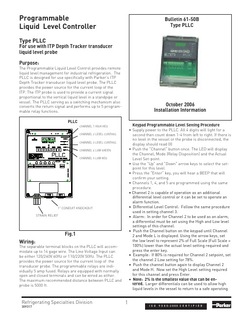
Refrigerating Specialties Division13093172 and Mode L is displayed. Using the arrow keys, set the low level to represent 2% of Full Scale (Full Scale = 100%) lower than the actual level setting required and press the enter key.• Example: If 80% is required for Channel 2 setpoint, set the channel 2 Low setting for 78%.• Push the channel button again to display Channel 2 and Mode H. Now set the High Level setting required for this channel and press Enter.• Note: 2% is the smallest value that can be en-tered. Larger differentials can be used to allow high liquid levels in the vessel to return to a safe operatingWiring:The separable terminal blocks on the PLLC will accom-modate up to 14 gage wire. The Line Voltage Input can be either 120/240V 60Hz or 110/220V 50Hz. The PLLC provides the power source for the current loop of the transducer probe. The programmable relays are indi-vidually 5 amp fused. Relays are equipped with normally open and closed terminals and can be wired as either. The maximum recommended distance between PLLC and probe is 5000 ft.Refrigerating Specialties Division2equipment failure."High" level setting.•channel.selected.First Modechange.Second ModeFig. 22445 S.25th Ave Broadview Ill 60155T708-681-6300 F708-681-6306。
音叉式液体限位开关操作手册-E H

KA 143F/00/a6 52002410
音叉式液体限位开关 Liquiphant M FTL 50,FTL 51
首页
内容
打印
退出
内容
安全注意事项
3
搬运
4
仪表型号
F##
K## N## GE2 R3/ , DIN2999(BSPT) ,
1.44 435 / A I S I 3 1 6 L
GE5 R3/ , DIN2999(BSPT) , 4 2.4610(Alloy C4)
GF2 R 1, DIN2999(BSPT) , 1.4435/AISI 3 1 6 L
2 FEL52,U=:10...55V
PNP-Transistor
2
4 FEL54,U~:19...253V,
U=19...55 V 5 FEL55,11...36V,8 / 16mA,E E x i a
31.. ..38
6 FEL56,NAMUR(EN50227),L-H, EExia
7 FEL57,PFM,EExia
4
1 1 / ",1 5 0 p s i, RF,AISI316L
1
1
/
2 2
",3
0
0
p
s
i,
RF
,
A
I
S
I
3
1
6
L
2 ", 1 5 0 p s i, RF,AISI316L
2 ", 2 ",
1 5 0 p s i, RF,AISI316L+2.4610(AlloyC4) 3 0 0 p s i, RF,AISI316L
VEGASWING音叉开关操作说明书

1 安全提示1.1 被授权的仪表操作人员处于安全考虑,在这本说明书中所介绍的各种操作,需要经过培训和授权的技术人员来完成。
1.2 应用VEGASWING用于位式检测液体介质。
1.3 使用错误的警示如果应用不正确或不符合规定,从应用角度讲,由于安装或调试错误,容器会溢出介质或损坏设备。
1.4 安全介绍在安装和操作仪表的时候,需要注意有关的安全规定(比如:在德国需要符合VDE-规定)。
1.5 CE – 认证VEGASWING系列经过CE认证,满足NAMUR-要求NE21。
CE-认证根据以下标准:• EMVG:- Emission EN 61326:1997(A级)- Immission EN 61326:1997/A1:1998• NSR: EN 61010-1: 20011.6 符合SILVEGASWING符合功能安全的要求,符合IEC61508/IEC61511。
1.7 防爆应用的注意事项对于防爆应用,要注意防爆安全规定。
每个防爆仪表都会随附防爆合格证,要注意防爆参数。
1.8 环保事项环境保护现在已经成为最为紧要的任务。
因此VEGA公司也建立了完善的环保管理体系,且获得EN ISO14001认证。
请您帮助我们,完成环保的使命,见以下两章:• “仓储和运输”• “清除废料”2 产品介绍2.1 构造供货范围• 音叉式位式检测仪表VEGASWING• 文件资料- 此操作说明书- 您订购的各类相应的许可证,比如:如果您购买的是防爆型的仪表,随附防爆许可证组件VEGASWING60系列由以下组件组成:• 仪表罩盖• 外壳带电子部件,可选带插头连接• 过程连接和音叉1 外壳罩盖2 外壳,带电子部件3 过程连接VEGASWING51系列由以下组件组成:• 外壳带电子部件• 过程连接和音叉2.2 工作原理应用范围VEGASWING用于位式检测液体物位。
典型的的应用是溢出保护和防止空转。
音叉最短只有40mm,因此可以安装到最细DN25的管道上。
音叉密度计说明书(精品pdf)

DMF-1-CR 插入式密度计第一部分 介绍 (3)1.DMF-1-CR介绍 (3)2.适用范围 (3)3. 工作原理 (3)4. 特点 (4)5.技术参数 (4)第二部分 机械安装 (5)1.概述 (5)2.流速的计算 (5)3.安装定位 (5)3.1概述 (5)3.2典型安装方式示意图 (6)3.3试用转 (8)第三部分 电气安装 (8)1.介绍 (8)第四部分 注意事项 (9)第五部分密度计操作说明 (10)第六部分 仪表选型指南 (13)第一部分 介绍1.DMF-1-CR介绍DMF-1-CR插入式密度计采用插入式安装,广泛适用于管路,开阔的罐体容器和封闭的罐体容器中的介质密度检测。
流体密度直接取决于传感器插入介质中音叉收到的振动频率。
传感器内置温度传感器为其提供温度补偿。
2.适用范围DMF-1-CR插入式密度计可实时在线的进行密度检测。
它可以运用于以密度为基本参数产品的过程控制或者以固体百分比或浓度百分比为参照质量控制中。
典型行业包括,石油化工行业,酿酒业,食品行业,制药行业和矿物加工(如粘土,碳酸盐、硅酸盐等),具体应用于以上行业中的多产品管道中的界面检测,搅拌混合物的密度检测,反应釜终点监测,离析器界面检测。
3. 工作原理传感器基于元器件振动原理工作,元器件部分为浸入被测液体中的音叉部分。
音叉部分通过内在的固定于叉体底部一端的压电设备感应振动。
震荡频率由固定于叉体另一端的二次压电设备来检测,然后通过顶部的电路放大信号。
液体密度和被测液体流动时的震动频率密切相关,当被测液体密度变化时,液体流动时的振动频率也随之改变。
通过以下方程,被测液体的密度可以被精确的计算出来。
D= K0+K1T+K2T2D=未校准的被测介质密度(kg/m3)T=振动频率(μs).K0、K1、K2=常量在密度检测过程中,DMF-1-CR插入式密度计可以自动补偿温度对被测介质密度(D)的影响,压力对密度没有显著的影响。
液位开关说明书

外贴式液位开关隔爆型安装使用说明书(201405A)陕西声科电子中国西安高新技术产业开发区©本说明书的版权和最终解释权归声科电子有限公司所用。
目录1.使用说明 (1)2.仪表保修及服务范围 (1)3.仪表技术性能 (2)4.开箱检验及注意事项 (2)4.1 开箱检验 (2)4.2 注意事项 (3)5.仪表各部件 (3)6.仪表安装 (4)6.1 超声波探头的安装 (4)6.2 仪表主机安装 (8)6.3仪表的安装方式 (11)7.仪表电气连接 (12)7.1 仪表电气连接图 (12)7.2 仪表供电 (12)8. 仪表设置及使用 (13)8.1 仪表参数设置人机接口说明 (13)8.2 仪表操作目录树 (14)8.3 仪表运行界面示意 (15)8.4 仪表校准操作 (16)8.5仪表校准操作图示 (16)9.外贴式液位开关选型表 (19)10.仪表适用范围 (20)11.性能指标 (20)12.仪表故障处理 (21)1、使用说明本说明书全面阐述了外贴式液位开关的安装、操作及使用方法。
通过本说明书,用户可以顺利的完成对外贴式液位开关的安装、使用及维护工作。
本说明书的编制是以外贴式液位开关的安装、操作步骤为顺序,详细介绍了您在安装、使用仪表的每个环节需要完成的工作及注意事项。
在您安装、使用该仪表之前,请详细阅读本说明书。
2、仪表保修及服务范围自发货之日算起,仪表主机保修期为一年,仪表修理及维护的保修期为半年,此保修仅限于原始购买者及或声科电子指定经销商的仪表使用用户,而不适用于任何声科电子认为因错误使用,改造、疏忽或因事故及非正常情况下使用而导致损坏的仪表。
对于在保修范围内的送回声科电子的有故障的仪表,声科电子提供免费维修。
要获得保修服务,请联系声科售后服务部并附上故障说明,经本公司许可后,将仪表寄往声科售后服务部。
如果仪表已过质保期或声科电子确认仪表故障是由于错误使用、改造、疏忽、事故及非正常条件下使用导致的,声科电子将依据外贴式液位开关维修收费标准提供维修费用预算,并在得到认可后进行维修。
L-Series 001 L178 L195垂直安装液位浮球开关 安装和操作手册说明书
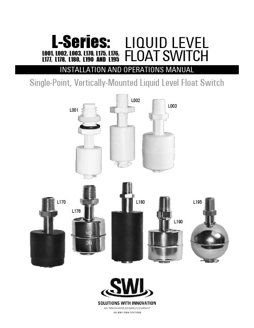
L-Series:LIQUID LEVELFLOAT SWITCHSingle-Point, Vertically-Mounted Liquid Level Float SwitchL001, L002, L003, L170, L175, L176, L177, L178, L180, L190 AND L195L001L002L003L170L176L180L190L1952L-SERIES SINGLE-POINT, VERTICALLY-MOUNTED LIQUID LEVEL FLOAT SWITCHThis manual provides information on the L-Series,Single-Point, Vertically-Mounted Liquid Level Float Switch . It is important that all instructionsare read carefully and followed sequentially. Detailed instructions are included in the Complete Installation section of this manual.Conventions Used in this ManualCertain conventions are used in this manual to convey specific types of information. General technical material, support data and safety information are presented in narrative form. The following styles are used for notes, cautions and warnings:NotesNotes contain information that augments or clarifies an operating step. Notes do not normally contain actions and often follow the procedural steps to which they refer.CautionsCautions alert the technician to special conditions that could injure personnel, damage equipment, or reduce a component’s mechanical integrity. Cautions are also used to alert the technician of unsafe practices, the need for special protective equipment, or specific materials. In this manual, a caution indicates a potentially hazardous situation which, if not avoided, may result in minor to moderate injury.Notice of Copyright and LimitationsCopyright © 2015 Solutions With Innovation, LLC; All rights reserved.Solutions With Innovation reserves the right to make changes to the product described in this manual at any time without notice. Solutions With Innovation makes no warranty with respect to the accuracy of the information in this manual.WarrantyAll Solutions With Innovation Mechanical Level and Flow Controls are warranted free of defects in materials and workmanship for one full year from the date of the original factory shipment. If returned within the warranty period; and, upon factory inspection of the control, the cause of the claim is determined to be covered under the warranty; then, Solutions With Innovation will repair or replace the product at no cost to the purchaser (or owner) other than transportation.Solutions With Innovation shall not be liable for misapplication, labor claims, direct or consequential damage, or expenses arising from the installation or use of the equipment. There are no other warranties expressed or implied, except special written warranties covering specific Solutions With Innovation products.Quality AssuranceThe Quality Assurance System in place at Solutions With Innovation guarantees the highest level of quality throughout the company. Solutions With Innovation is committed to providing full customer satisfaction; both in quality products and in quality service.ContactsPhone: 203-729-6434 Mon-Fri, 9 AM - 5 PM EST Fax: 203-729-0541 for General Inquiries Email:***************************READ THIS MANUAL PRIOR TO INSTALLATION3L-SERIES SINGLE-POINT, VERTICALLY-MOUNTED LIQUID LEVEL FLOAT SWITCHL-Series:LIQUID LEVEL FLOAT SWITCHSingle-Point, Vertical MountTABLE OF CONTENTSL001, L 002, L 003, L 170, L 175, L 176, L177, L178, L180, L190 AND L1951.0 Installation1.1 Unpacking.............................................................................41.2 Before You Begin................................................................4 1.2.1 Site Preparation...........................................................4 1.2.2 Equipment and Tools. (4)1.3 Mounting...............................................................................5 1.3.1 Threaded Mounting. (5)1.4 Wiring....................................................................................52.0 Preventative Maintenance2.1 What To Do..........................................................................6 2.1.1 Inspect Entire Unit Periodically.................................6 2.1.2 Inspect Connections Monthly...................................6 2.1.3 Keep Unit Clean. (6)2.2 What To Avoid.....................................................................63.0 Reference Information3.1 Description...........................................................................73.2 Theory of Operation..........................................................73.3 Troubleshooting...................................................................7 3.3.1 External Causes...........................................................7 3.3.2 Unit Causes. (8)3.4 Agency Approvals................................................................83.5 Specifications........................................................................9 3.5.1 Physical Specifications................................................9 3.5.2 Electrical Specifications..............................................9 3.5.3 Dimensional Specifications......................................103.6 Notes...................................................................................103.7 Model Configurator...........................................................113.8 Replacement Parts. (11)1.0 INSTALLATIONThis section provides detailed procedures on properly installing the L-Series Single-Point, Vertically-Mounted Liquid Level Float Switch.CAUTION! IF THE EQUIPMENT IS USED IN A MANNER NOT SPECIFIED BY THE MANUFACTURER, PROTECTION PROVIDED BY THE EQUIPMENT MAY BE IMPAIRED.1.1 UNPACKINGUnpack the instrument, carefully. Make sure that all components have been removed from the packing material. Inspect all components for damage. Report any concealed damage to the carrier within 24 hours of receiving. Compare the contents with the packing slip and report any discrepancies to the factory immediately. Record the sales order number and/or serial number for future reference when ordering parts.Before Proceeding to Installation, Complete the Following:• Inspect all components for damage. Report any damage to the carrier within 24 hours of receiving.• Record the model and serial numbers for future reference when ordering parts.Model NumberSerial Number1.2 BEFORE YOU BEGINCAUTION! DURING THE INSTALLATION OF THE SINGLE-POINT, VERTICALLY-MOUNTED LIQUID LEVEL SWITCH, THE FLOAT AREA MUST BE KEPT FREE OF METALLIC PARTICLES THAT MIGHT BE ATTRACTED TO THE FLOAT’S INTERNAL MAGNET.1.2.1 Site PreparationEnsure that the length and the inside diameter of the mounting is sized correctly to accommodate the L-Series Single-Point, Vertically-Mounted Liquid Level Float Switch.1.2.2 Equipment and ToolsNo special equipment or tools are required to install the L-Series Single-Point, Vertically-Mounted Liquid Level Float Switch.The Following Are Recommended:• Wrenches, thread sealant, gaskets and/or bolting as required for the process connection.4L-SERIES SINGLE-POINT, VERTICALLY-MOUNTED LIQUID LEVEL FLOAT SWITCH5L-SERIES SINGLE-POINT, VERTICALLY-MOUNTED LIQUID LEVEL FLOAT SWITCH1.3 MOUNTINGThe L-Series Single-Point, Vertically-Mounted Liquid Level Float Switch is available in a variety of threaded mountings. These devices can be installed from the bottom or top of the tank. The switches should be mounted in an area clear of turbulence or direct streams.1.3.1 Threaded MountingHow to Install an L-Series Single-Point, Vertically-Mounted Liquid Level Switch:1 Apply either Teflon ® tape or an appropriate thread sealant to the mounting threads to prevent galling.2 Engage the thread by hand to avoid unnecessary damage.3 Using a wrench, rotate the unit clockwise until it is tight within the mounting.1.4 WIRINGCAUTION! OBSERVE ALL APPLICABLE ELECTRICAL CODES AND PROPER WIRING PROCEDURES.Contact Protection:In order to maintain the life and reliability of the internal reed switch, it is essential to provide protection when switching inductive loads. When the current breaks, the energy stored in the load generates a high frequency voltage across the switch contacts. If the voltage is large enough, it can initiate arcing and cause the contacts to weld together. Damage can ultimately be prevented by suppressing the voltage. Through the use of a diode for DC circuits and a resistor-capacitor network for AC circuits, contact protection willensure reliable performance from the reed switch.TOP MOUNT BOTTOM MOUNTANGLED MOUNT6L-SERIES SINGLE-POINT, VERTICALLY-MOUNTED LIQUID LEVEL FLOAT SWITCH2.0 PREVENTATIVE MAINTENANCEPeriodic inspections are necessary to maintain the proper functionality of the L-Series Single-Point, Vertically-Mounted Liquid Level Switch. The switch is a safety device that protects the equipment it serves. A systematic program of preventative maintenance should be implemented at the time of installation. If the following instructions are completed routinely, the switch will provide continuous, reliable protection.2.1 MAINTENANCE PROCEDURES 2.1.1 Inspect Unit PeriodicallyVerify that there are no cracks or chipped surfaces on the float or stem. Should the unit become damaged, obtain a replacement immediately.2.1.2 Inspect Connections MonthlyL-Series Single-Point, Vertically-Mounted Liquid Level Switches may be vulnerable to excessive heat and moisture. Under these conditions, the electrical wire insulation can periodically break or peel away. As a result, the bare wires may become exposed to the elements and cause damages.• Inspect all wiring, carefully and replace any wires exhibiting signs of brittle insulation.• Inspect all electrical connections to ensure tightness.• Repair or replace any wiring, if necessary.2.1.3 Keep Unit CleanPeriodic cleanings of the float, stem and magnet assembly will ensure the continual, uninterrupted movement of the mechanism. Always keep the open area between the enclosures clean and free of any potential interferences. Objects and debris may cause systematic interruptions and a loss in equipment functionality.2.2 WHAT TO AVOIDNEVER LEAVE THE SWITCH WIRING EXPOSED TO THE ELEMENTS.NEVER PLACE A JUMPER WIRE ACROSS THE TERMINALS TO “CUT-OUT” THE CONTROL. If a jumper is necessaryfor testing purposes, ensure that it is removed prior to placing the control into service.NEVER USE IN SYSTEMS CONTAINING IRON PARTICLES. The magnet within the float assembly can attract the particlesand become jammed.3.0 REFERENCE INFORMATIONThis section illustrates an overview of the L-Series Single-Point, Vertically-Mounted Liquid Level Switch, as well as information on troubleshooting common problems, agency approval listings, and detailed physical, functional and performance specifications.3.1 DESCRIPTIONThe L-Series Single-Point, Vertically-Mounted Liquid Level Switchis a float-actuated device designed to be vertically mounted within atank or process vessel through threaded connections. The low-costswitch is ideal for OEM applications where a single-point high or lowlevel alarm is desired.3.2 THEORY OF OPERATIONThe switching action is achieved through the use of an internalmagnet within the float assembly and its interaction with the switchmechanism. As the liquid level fluctuates inside the tank, the floatfollows. Its magnetic field actuates the switch inside the stem andcloses an electrical circuit.FLOAT SWITCH DIAGRAM3.3 TROUBLESHOOTINGThe L-Series Single-Point, Vertically-Mounted Liquid Level Switch is designed and engineered for trouble-free operation over a wide range of operating conditions. Common problems are discussed in terms of their symptoms and recommended corrective actions.3.3.1 External CausesAn initial indication of improper operation is the failure of the controlled equipment to function (pumps will not start or stop, signal lamps fail to light, etc). If these symptoms occur, whether at the time of installation or during routine service thereafter, check for potential external causes first:• Blown Fuses• Tripped Reset Button(s)• Open Power Switch• Faulty Equipment Controlled By the Level Switch• Defective Wiring to the Level SwitchL-SERIES SINGLE-POINT, VERTICALLY-MOUNTED LIQUID LEVEL FLOAT SWITCH78L-SERIES SINGLE-POINT, VERTICALLY-MOUNTED LIQUID LEVEL FLOAT SWITCH3.3.2 Unit CausesIf a thorough inspection of any external causes fails to locate the problem, proceed to an inspection of the unit, itself.DISCONNECT POWER TO THE LEVEL SWITCH BEFORE PROCEEDING.If you are still in doubt about the condition or performance of your control, consult the factory for further instructions.3.4 AGENCY APPROVALS3.5 SPECIFICATIONS3.5.1 Physical Specifications3.5.2 Electrical SpecificationsL-SERIES SINGLE-POINT, VERTICALLY-MOUNTED LIQUID LEVEL FLOAT SWITCH910L-SERIES SINGLE-POINT, VERTICALLY-MOUNTED LIQUID LEVEL FLOAT SWITCH3.5.3 Dimensional Specifications3.6 NOTESHEX11L-SERIES SINGLE-POINT, VERTICALLY-MOUNTED LIQUID LEVEL FLOAT SWITCH3.7 MODEL CONFIGURATOR3.8 REPLACEMENT PARTSWhen Ordering, Please Specify:• Model & Serial Numbers• Name & Part Number of Replacement Part or AssemblyAll replacement parts are for standard models only. Contact the manufacturer for ordering assistance on all specially modified models (model numbers followed by a “C”; i.e. L003C, L177C, etc.)STEM & SWITCH SUB-ASSEMBLYFLOATCLIPService PolicyOwners of Solutions With Innovation products may request a return of the product, or any part of the product for complete rebuilding or replacement. Units will be rebuilt or replaced promptly. Products returned under the SWI Service Policy must be returned by prepaid transportation. Solutions With Innovation will repair or replace the product at no cost to the purchaser (or owner) other than transportation if:1 Returned within the warranty period; and2 Factory Inspection finds the cause of the claim to be covered under the warranty.If the problem is due to circumstances beyond Solutions With Innovation’s liability, or is NOT covered by the warranty, there will be charges for labor in addition to the parts required to rebuild or replace the equipment.In rare cases, it may be expedient to ship replacement parts; or in extreme cases, an entire product before the damaged product is returned. If a quick replacement service is necessary, notify the manufacturer of the damaged product’s model and serial number. In such cases, credit for the returned materials will be determined on the applicability of the warranty.No claims for misapplication, labor, direct or consequential damage will be allowed.Return Material ProcedureIn order to efficiently process any returned materials, it is essential that a Return Material Authorization (RMA) number be obtained from the manufacturer prior to an item’s return. RMA’s can be issued through local representatives, or by contacting the factory directly. Please supply the following information: 1 The Company’s Name 2 Description of the Material 3 Product Serial Number 4 Reason for Return 5 Product’s ApplicationUsed units must be properly cleaned in accordance with OSHA standards before it is returned to the manufacturer. A Material Safety Data Sheet (MSDS) must accompany units or materials that were used in any type of media. All return shipments to the factory must be by done via prepaid transportation. All product replacements will be shipped F.O.B. manufacturer.BULLETIN: IS-9110.2EFFECTIVE: 1/15。
Endress+Hauser Liquiphant FTL64 液体音叉开关操作手册说明书

Products Solutions Services操作手册Liquiphant FTL64液体音叉开关液体音叉开关,适用高温工况BA02037F/28/ZH/03.22-00715701032022-02-18适用固件版本号:01.01.zz (设备固件)Liquiphant FTL642Endress+HauserLiquiphant FTL64目录Endress+Hauser3目录1文档信息 (5)1.1文档用途.............................51.2图标................................51.2.1安全图标......................51.2.2电气图标......................51.2.3工具图标......................51.2.4特定信息图标...................51.2.5图中的图标.....................51.2.6注册商标......................62基本安全指南 (6)2.1人员要求.............................62.2指定用途.............................62.2.1使用错误......................62.3工作场所安全.........................72.4操作安全.............................72.5产品安全.............................72.6SIL 功能安全认证(可选)...............72.7IT 安全..............................73产品描述 (7)3.1产品设计 (8)4到货验收和产品标识 (8)4.1到货验收.............................84.2产品标识.............................84.2.1铭牌..........................94.2.2电子插件......................94.2.3制造商地址.....................94.3储存和运输...........................94.3.1储存条件......................94.3.2运输设备......................95安装 (10)5.1安装要求............................105.1.1注意带PFA 涂层(导电)的仪表的温度........................105.1.2注意开关点....................115.1.3注意介质粘度的影响.............115.1.4避免黏附.....................125.1.5预留安装间隙..................135.1.6支撑设备.....................135.2安装仪表............................145.2.1所需工具.....................145.2.2安装.........................145.3滑动套管............................155.4安装后检查..........................156电气连接 (16)6.1所需工具............................166.2接线要求............................166.2.1带锁定螺丝的外壳盖. (16)6.2.2连接保护性接地端(PE).........166.3连接设备............................166.3.1电子插件FEL61:两线制连接,交流AC 型 .....................176.3.2电子插件FEL62:三线制连接,直流DC-PNP 型..................196.3.3电子插件FEL64:通用电流连接型,带继电器输出..............216.3.4电子插件FEL64 DC:直流连接型,带继电器输出.................236.3.5电子插件FEL67:PFM 输出.......256.3.6电子插件FEL68:两线制连接,NAMUR 信号(> 2.2 mA/ < 1.0 mA).....................276.3.7LED 指示灯VU120(选配).......296.3.8蓝牙模块VU121(选配)........316.3.9连接电缆 .....................326.4连接后检查..........................337操作方式 (34)7.1操作方式概览........................347.1.1操作方式 .....................347.1.2电子插件上的部件..............347.1.3通过Bluetooth®无线技术实现心跳自诊断和心跳自校验............347.1.4LED 指示灯VU120(选配).......358调试 (35)8.1功能检查............................358.2使用电子插件上的按键执行功能测试......358.2.1FEL61的继电器响应和故障报警信号........................368.2.2FEL62的继电器响应和故障报警信号........................378.2.3FEL64、FEL64DC 的继电器响应和故障报警信号.................378.2.4FEL67的继电器响应和故障报警信号........................378.2.5FEL68的继电器响应和故障报警信号........................398.3使用测试磁铁进行电子开关的功能测试.....398.4开机...............................398.5通过SmartBlue app 建立连接............408.5.1前提条件.....................408.5.2准备步骤.....................408.5.3通过SmartBlue app 建立连接......409操作 (42)9.1诊断菜单............................429.1.1“诊断信息” 菜单................429.1.2“应用” 菜单...................429.1.3“系统” 菜单...................439.2心跳自校验..........................449.3SIL/WHG 认证型设备的功能安全测试......44目录Liquiphant FTL644Endress+Hauser10诊断和故障排除 (44)10.1通过LED 指示灯标识诊断信息...........4510.1.1电子插件上的LED 指示灯.........4510.1.2SmartBlue ....................4510.2固件更新历史........................4511维护 (46)11.1维护任务 (46)11.1.1清洁 (46)12维修 (46)12.1概述...............................4612.1.1维修理念.....................4612.1.2防爆型设备的维修..............4612.2备件...............................4612.3返厂...............................4712.4处置...............................4712.5废电池处置 .........................4713附件 (47)13.1设备浏览器..........................4713.2测试磁铁............................4713.3防护罩,适用双腔室铝外壳..............4713.4保护盖,适用单腔室铝外壳或316L 外壳...4813.5插头...............................4813.6蓝牙模块VU121(选配)...............4913.7LED 模块VU120(选配)...............4913.8常压滑动套管........................5013.9高压滑动套管........................5114技术参数 (53)14.1输入...............................5314.1.1测量变量 .....................5314.1.2测量范围.....................5314.2输出...............................5314.2.1输出与输入....................5314.2.2输出信号.....................5414.2.3防爆连接参数 .................5414.3环境条件............................5414.3.1环境温度范围..................5414.3.2储存温度.....................5514.3.3湿度.........................5614.3.4海拔高度.....................5614.3.5气候等级 .....................5614.3.6防护等级.....................5614.3.7抗振性.......................5614.3.8抗冲击性.....................5614.3.9机械负载.....................5614.3.10污染等级.....................5614.3.11电磁兼容性....................5614.4过程条件............................5714.4.1过程温度范围..................5714.4.2介质条件.....................5714.4.3热冲击 .......................5714.4.4过程压力范围..................5714.4.5测试压力 (58)14.4.6密度.........................5814.4.7粘度.........................5814.4.8密闭压力.....................5814.4.9固体颗粒尺寸..................5814.5其他技术参数 (59)索引 (60)Liquiphant FTL64文档信息Endress+Hauser 51文档信息1.1文档用途文档包含设备生命周期内各个阶段所需的所有信息:从产品标识、到货验收和储存,至安装、电气连接、操作和调试,以及故障排除、维护和废弃。
干簧式液位开关说明书

干簧式液位开关说明书干簧式液位开关是一种常用于测量液位和流量的仪器。
它使用磁场原理,利用磁性元件和干簧管的特性来实现液位的检测和控制。
本说明书将为您详细介绍干簧式液位开关的工作原理、特点、安装及维护保养等方面的信息。
一、工作原理干簧式液位开关是一种电磁式液位开关,由可以吸附铁磁性物质的磁性元件和内部装有金属叶片的干簧管组成。
当液位达到开关的设定值时,磁性元件会被吸附到干簧管附近的磁性吸铁体上,导致干簧管受力发生弯曲,金属叶片与干簧管接触形成闭合回路,输出控制信号,从而实现测量和控制。
二、特点1. 高可靠性:采用干簧管作为触点,无接触式操作,具有寿命长、反应速度快、耐腐蚀等优点,使用寿命达到数十万次以上。
2. 易安装:适用于各种管道、贮槽等液位测量场合,安装简单方便,且可以根据需要灵活设置触点数目和位置。
3. 精度高:可根据要求设置开关的启、停、差值等参数,具有较高的精度和可靠性。
4. 适用范围广:可广泛应用于化工、石油、医药、食品、造纸等行业中的液位、流量控制和报警等领域。
三、安装及维护保养1. 安装前应检查开关、磁性元件和干簧管等部件是否完好,尽量保证其处于干燥、无异味且通风良好的环境中,避免影响其性能。
2. 安装时应将开关固定在管道的合适位置,并根据需要设置触点参数,调整开关的灵敏度。
3. 在使用过程中,应定期检查开关的性能、触点的清洁程度、接线是否松动等情况,并对开关及其周边部分进行保养、清洗。
4. 在长期运行过程中,如发现开关失灵、触点断开、磁性元件磨损等情况,应及时更换相应部件,确保其正常运行。
总之,干簧式液位开关是一种性能稳定、使用方便、精度高的液位测量仪器。
在实际应用中,需要严格按照说明书所述进行安装、使用及维护,以保证其正常运行,提高生产效率和品质,提升企业的经济效益。
- 1、下载文档前请自行甄别文档内容的完整性,平台不提供额外的编辑、内容补充、找答案等附加服务。
- 2、"仅部分预览"的文档,不可在线预览部分如存在完整性等问题,可反馈申请退款(可完整预览的文档不适用该条件!)。
- 3、如文档侵犯您的权益,请联系客服反馈,我们会尽快为您处理(人工客服工作时间:9:00-18:30)。
上海驰控音叉液位开关ckyc-001说明书
一、安装指南
(1)安装前说明
在安装之前,请再次确认仪表型号是否满足现场的环境要求,如:过程压力、过程温度、介质的化学性能等,确保仪表在安装后能够正常使用。
(2)安装
一般地,音叉液位开关可以根据需要安装在任何位置,可以水平安装、也可以垂直安装或倾斜安装。
当被测介质具有粘稠性时,为了减少或避免出现挂料现象,请将仪表垂直安装。
(3)安装方向
安装音叉液位开关时,应使叉体面和液体升降或流动保持方向一致,可以避免挂料或由于介质对叉体的阻力而产生的测量误差。
(4)避开入料口
如图2,音叉液位开关安装位置的选择时,应避免由于安装在入料口位置而造成的测量误差,甚至损坏仪表。
(5)压力/真空
对于过压或欠压的容器或管道,必须保证过程连接处的密封完好性。
安装之前应确认好密封材料是否满足现场过程温度和过程压力的要求。
(6)防潮
当仪表安装在户外或有潮气的环境中,如遇到下雨或村在冷凝现象时,雨水和冷凝水便会随之往下流,所以在接入电缆之前,请将电缆线弯曲并朝下引,以防止水或潮气进入仪表,如图3所示。
二、接电
(1)安全提示
(a)从安全角度考虑,只有在断电的情况下才能进行接线;
(b)对于防爆型仪表接线时必须遵循相关防爆的接线要求。
(2)接入电缆
音叉液位开关的电缆一般采用横截面为圆形的通用电缆。
电缆横截面直径为5-9mm,否则无法确保电缆入口的密封效果。
如果您需要使用其它规格的电缆,请使用匹配的电缆入口螺栓,并注意更换后电缆入口的密封性能。
(3)接线图
接线时,请按照如图4和5所示方式进行安全接线。
(4)接线步骤
对于隔爆型仪表,只有当环境中不存在会引爆的气体或粉尘时才允许打开外盖操作。
请按照如下步骤进行操作:
(a)打开外壳盖;
(b)松开电缆螺纹接头上的锁紧螺母;
(c)去掉连接电缆大约10cm的外皮和芯线末端大约1cm的绝缘层;
(d)将电缆穿过电缆螺纹接头插入外壳中;
(e)用螺丝刀打开接线端子;
(f)按照接线图将芯线末端插入接线端子中;
(g)用螺丝刀拧紧接线端子;
(h)通过轻拉接入的电缆线来检查接线是否牢靠;
(i)拧紧电缆螺纹接头的锁紧螺母,扣紧密封环;
(j)拧上外壳盖。
三、调试
(1)内部结构
如图6和图7所示。
(2)密度开关(灵敏度)
通过控制面板上的密度调节开关可改变音叉液位开关的测量灵敏度,使之更好的适应被测液体。
音叉液位开关的密度开关在出厂时位于下档位,最低测量密度为0.7g/cm³;当遇到密度特别低的液体时,可将密度开关拨到上档位,此时最低测量密度可达0.5g/cm³,
使得检测更加灵敏,测量的可靠性更高。
(3)高低位模式转换
对于溢流保护和防干运行的两种限位报警功能,需结合现场实际要求来调节仪表的高低位模式(High/Low)开关,最终达到客户所需要的信号输出状态,具体功能请参照本说明书5.5节“信号输出功能表”。
(4)指示灯
用于显示开关状态的指示灯
绿色=正常工作状态
红色=报警状态
红色(闪烁)=故障状态。