如何调试音叉液位开关的灵敏度
音叉式液体限位开关操作手册-E H

KA 143F/00/a6 52002410
音叉式液体限位开关 Liquiphant M FTL 50,FTL 51
首页
内容
打印
退出
内容
安全注意事项
3
搬运
4
仪表型号
F##
K## N## GE2 R3/ , DIN2999(BSPT) ,
1.44 435 / A I S I 3 1 6 L
GE5 R3/ , DIN2999(BSPT) , 4 2.4610(Alloy C4)
GF2 R 1, DIN2999(BSPT) , 1.4435/AISI 3 1 6 L
2 FEL52,U=:10...55V
PNP-Transistor
2
4 FEL54,U~:19...253V,
U=19...55 V 5 FEL55,11...36V,8 / 16mA,E E x i a
31.. ..38
6 FEL56,NAMUR(EN50227),L-H, EExia
7 FEL57,PFM,EExia
4
1 1 / ",1 5 0 p s i, RF,AISI316L
1
1
/
2 2
",3
0
0
p
s
i,
RF
,
A
I
S
I
3
1
6
L
2 ", 1 5 0 p s i, RF,AISI316L
2 ", 2 ",
1 5 0 p s i, RF,AISI316L+2.4610(AlloyC4) 3 0 0 p s i, RF,AISI316L
音叉液位开关检测方法
音叉液位开关检测方法音叉液位开关是一种常用的流量控制设备,在液位测量领域广泛应用。
但是,在实际使用中,由于液体的特性、环境因素等原因,可能会造成音叉液位开关的误判或故障。
为了保障设备的正常运行,采取一系列的检测方法是非常必要的。
本文将详细介绍音叉液位开关检测方法。
一、物理检测通过对物理信号的观察和测试,判断音叉液位开关的状态是否正常。
1、声波测试法使用声音记录仪,对液位开关进行测试,通过声音波动的变化,判断开关是否工作正常。
方法如下:(1)静音状态记录基准值;(2)在液位低或高于开关时,记录音波值;(3)对比基准值和音波值,判断液位开关是否正常。
2、物理动作测试法在音叉液位开关的发声频率范围内,使用加速度传感器进行测试,包括频率响应曲线的测试、振动测试等。
通过测试数据,判断音叉液位开关的敏感性和响应速度是否正常。
二、接口检测1、电压测试法在音叉液位开关接口的信号传输线上,使用多用表进行测试,测试数据是否符合设备规格和标准。
2、物理平衡测试法在数据接口处,使用平衡仪进行测试。
通过观察设备的物理平衡状态,判断数据接口传输能否正常进行。
三、软件检测通过软件测试,判断音叉液位开关的数据计算、解析、显示等功能是否正常。
1、软件升级测试法进行软件升级,通过测试修复存在的Bug,提高软件运行效率。
2、数据解析测试法通过对液位开关产生的数据进行解析,判断数据解析是否正确、数据传输是否正常。
以上三种检测方法都可以有效提高音叉液位开关的实用性和可靠性。
在实际使用中需结合实际情况选择合适的检测方法,并建立完善的维护保养机制,提高设备的使用寿命。
音叉液位开关说明书

9 电气连接
输出驱动指示灯:
四线制接法
电气连接
1 2 34
电源
AC 220V 或 DC 24V
输出驱动中间继电器:
1 2 34
电源
AC 220V 或 DC 24V
输出进入计算机:
1 2 34
电源
工控机 或P L C
电气连接 10
电气连接
A C 2 20V供电
三线制接法
1 2 34
现场
≈≈≈
负载 仪表间
叉体
插入深度 100 25
动作点标记 20
5 动作点
约15
说明:接线盒为铝合金压铸表面喷塑,其余为304不锈钢
图2
1 了解产品
了解产品
基本原理: LS-YC型音叉式液位开关是一种通用型的液位开关。音叉由压
电晶体激励产生振动,当音叉被液体或固体浸没时振动频率发生变 化,这个频率变化由电子线路检测出来并输出一个开关量,达到液 位报警或控制的目的。
W: 高温 型:小 于150℃
Y: 高压型:小 于2MPa
特
殊
B: 防 爆 型: dⅡBT4
型
F: 防 腐 型:聚四氟 喷 涂叉体
注: 特殊 型产品 可 复选参 数 。例如 : 介质温 度130℃, 介 质 腐 蚀 性强,DC 24V供 电,R1安 装接头,插 入 深度为300mm, 此 时 的完整 型 号为:LS-YC-WF-1-0-300。
② 电 器 接 口 不 要 冲 上,应 向 下 倾 斜 。
安装方法 6
安装方法
管道检测的安装方法:
管壁
说明:在管道中安装时方向标记应与液体流向一致。右图中安装方向会对测量 造成影响
音叉式物位开关说明书

☆产品简介:音叉式物位开关是一种新型的物位开关。
仪表由一个发讯叉体和放大器部分组成,在叉体根部压紧两组压电晶体,一组作为驱动器,驱动叉体产生振动,另一组作为检测器,用以将叉股转换成电压信号。
当叉股受阻时,振动器振幅变小,振动频率改变,继电器输出开关信号。
从而实现物位限位测量。
传感器材质为316不锈钢,可抗轻度腐蚀,用于限位控制器和高/低位报警。
☆工作原理:音叉式物位开关工作原理根据物料对振动中的音叉有无阻力,探知料位是否到达或超过某高度,并发出通断信号。
传感器的音叉以固有的频率振动,当音叉触及液体或其他物料时,其固有的振动频率降低,能量消耗在物料颗粒间的摩擦上,迫使振幅急剧衰减而停振,频率的变化激活液位开关,产生通断信号。
☆典型应用:●自来水、矿泉水●流动性好的固体粉料●可产生气体的液体●纸浆、胶水、染料●柴油等危险场所●废水、泥浆、酸碱溶液●啤酒、啤酒发酵剂、饮料一、拆箱小心的打开包装箱并除去包装箱内的填充物,仔细核对装箱单上的每项条款,包括仪表型号、安装附件、说明书等,若发现有缺货,与装箱单不符或破损现象,请立即与我公司联系。
二、查看说明书该说明书包括仪表的技术参数、安装及调试规范,请仔细阅读说明书中的每一项内容,如对说明书中的内容有不明白的地方,可以打电话或传真的方式与我公司联系。
三、技术参数●供电:24VDC(标准);220V AC(可选)●环境温度:-20℃~70℃●输出方式:SPDT继电器(单刀双掷)●介质温度:-40℃~150℃●工作压力:小于2MPa ●介质密度:最低0.6g/cm3●回差设置:约3mm ●功耗:0.5W●高低位报警:现场可设置为高位或地位报警●电气接口:M20*1.5●过程连接:NPT 1”螺纹安装(标准螺纹)法兰安装(可选)●外壳防护:IP66四、产品特点●适应性强:被测液体不同的电参数、密度对测量均不产生影响。
结垢、搅动、湍流、气泡、振动、中等粘度、高温、高压等恶劣条件对检测也无影响。
罗斯蒙特2110音叉液位开关说明书

Reference Manual00809-0100-4029, Rev AA July 2005Rosemount 2110Compact Vibrating Fork Liquid Level SwitchReference Manual00809-0100-4029, Rev AAJuly 2005Rosemount 2110 2110 Compact Vibrating ForkLiquid Level SwitchRead this manual before working with the product. For personal and system safety, and for optimum product performance, make sure you thoroughly understand the contents before installing, using, or maintaining this product.The United States has two toll-free assistance numbers and one International number. Customer Central1-800-999-9307 (7:00 a.m. to 7:00 P.M. CST)International1-(952) 906-8888National Response Center1-800-654-7768 (24 hours a day)Equipment service needsThe products described in this document are NOT designed for nuclear-qualified applications. Using non-nuclear qualified products in applications that require nuclear-qualified hardware or products may cause inaccurate readings.For information on Emerson Process Management nuclear-qualified products, contact your local Emerson Process Management Sales Representative.Rosemount pursues a policy of continuous development and product improvement. The specification in this document may therefore be changed without notice. To the best of our knowledge, the information contained in this document is accurate and Rosemount cannot be held responsible for any errors, omissions or other misinformation contained herein. No part of this document may be photocopied or reproduced without the prior written consent of Rosemount.Reference Manual00809-0100-4029, Rev AA Rosemount 2110July 2005Reference Manual00809-0100-4029, Rev AAJuly 2005Rosemount 2110 Table of ContentsSECTION 1IntroductionSwitch Overview . . . . . . . . . . . . . . . . . . . . . . . . . . . . . . . . . . . . . . . . . . . . . . . . . . . . . . . .1-2 Short Fork Technology. . . . . . . . . . . . . . . . . . . . . . . . . . . . . . . . . . . . . . . . . . . . . . . .1-2 Rosemount 2110 Application and Mounting Examples. . . . . . . . . . . . . . . . . . . . . . . . . . .1-2 Overfill Protection. . . . . . . . . . . . . . . . . . . . . . . . . . . . . . . . . . . . . . . . . . . . . . . . .1-3Pump Protection. . . . . . . . . . . . . . . . . . . . . . . . . . . . . . . . . . . . . . . . . . . . . . . . . .1-3High and Low Level Alarm. . . . . . . . . . . . . . . . . . . . . . . . . . . . . . . . . . . . . . . . . .1-3Leak Detection. . . . . . . . . . . . . . . . . . . . . . . . . . . . . . . . . . . . . . . . . . . . . . . . . . .1-3Pump Control. . . . . . . . . . . . . . . . . . . . . . . . . . . . . . . . . . . . . . . . . . . . . . . . . . . .1-3Hygienic Applications. . . . . . . . . . . . . . . . . . . . . . . . . . . . . . . . . . . . . . . . . . . . . .1-3 Application Considerations . . . . . . . . . . . . . . . . . . . . . . . . . . . . . . . . . . . . . . . . . . . . . . . .1-4 Handling the 2110. . . . . . . . . . . . . . . . . . . . . . . . . . . . . . . . . . . . . . . . . . . . . . . . . . . . . . .1-4 Rosemount Identification. . . . . . . . . . . . . . . . . . . . . . . . . . . . . . . . . . . . . . . . . . . . . . . . . .1-6 Installation Considerations and Recommendations . . . . . . . . . . . . . . . . . . . . . . . . . . . . .1-7 Switchpoint. . . . . . . . . . . . . . . . . . . . . . . . . . . . . . . . . . . . . . . . . . . . . . . . . . . . . . . . .1-8 Service Support. . . . . . . . . . . . . . . . . . . . . . . . . . . . . . . . . . . . . . . . . . . . . . . . . . . . . . . . .1-9 Warranty. . . . . . . . . . . . . . . . . . . . . . . . . . . . . . . . . . . . . . . . . . . . . . . . . . . . . . . . . . .1-9 SECTION 2InstallationSafety Messages. . . . . . . . . . . . . . . . . . . . . . . . . . . . . . . . . . . . . . . . . . . . . . . . . . . . . . . .2-1 Mechanical Installation . . . . . . . . . . . . . . . . . . . . . . . . . . . . . . . . . . . . . . . . . . . . . . . . . . .2-1 Correct Fork Alignment. . . . . . . . . . . . . . . . . . . . . . . . . . . . . . . . . . . . . . . . . . . . . . . . . . .2-2 Pipe Installation . . . . . . . . . . . . . . . . . . . . . . . . . . . . . . . . . . . . . . . . . . . . . . . . . . . . .2-2 Vessel Installation. . . . . . . . . . . . . . . . . . . . . . . . . . . . . . . . . . . . . . . . . . . . . . . . . . . .2-2 Cover Orientation . . . . . . . . . . . . . . . . . . . . . . . . . . . . . . . . . . . . . . . . . . . . . . . . . . . .2-3 Electrical Installation . . . . . . . . . . . . . . . . . . . . . . . . . . . . . . . . . . . . . . . . . . . . . . . . . . . . .2-4 Mode Selection. . . . . . . . . . . . . . . . . . . . . . . . . . . . . . . . . . . . . . . . . . . . . . . . . . . . . .2-4 LED Indication . . . . . . . . . . . . . . . . . . . . . . . . . . . . . . . . . . . . . . . . . . . . . . . . . . . . . .2-5 Function . . . . . . . . . . . . . . . . . . . . . . . . . . . . . . . . . . . . . . . . . . . . . . . . . . . . . . . . . . .2-6 Wiring . . . . . . . . . . . . . . . . . . . . . . . . . . . . . . . . . . . . . . . . . . . . . . . . . . . . . . . . . . . . .2-7 Reference Manual00809-0100-4029, Rev AA July 2005Rosemount 2110TOC-2SECTION 3Troubleshooting Magnetic Test Point. . . . . . . . . . . . . . . . . . . . . . . . . . . . . . . . . . . . . . . . . . . . . . . . . . . . . .3-1Inspection . . . . . . . . . . . . . . . . . . . . . . . . . . . . . . . . . . . . . . . . . . . . . . . . . . . . . . . . . . . . .3-1Maintenance . . . . . . . . . . . . . . . . . . . . . . . . . . . . . . . . . . . . . . . . . . . . . . . . . . . . . . . . . . .3-2Troubleshooting. . . . . . . . . . . . . . . . . . . . . . . . . . . . . . . . . . . . . . . . . . . . . . . . . . . . . . . . .3-2Spare Parts. . . . . . . . . . . . . . . . . . . . . . . . . . . . . . . . . . . . . . . . . . . . . . . . . . . . . . . . . . . .3-2APPENDIX AReference DataPhysical Specifications . . . . . . . . . . . . . . . . . . . . . . . . . . . . . . . . . . . . . . . . . . . . . . . . . . A-1Mechanical . . . . . . . . . . . . . . . . . . . . . . . . . . . . . . . . . . . . . . . . . . . . . . . . . . . . . . . . A-1Performance Specifications. . . . . . . . . . . . . . . . . . . . . . . . . . . . . . . . . . . . . . . . . . . . . . . A-2Functional Specifications. . . . . . . . . . . . . . . . . . . . . . . . . . . . . . . . . . . . . . . . . . . . . . . . . A-2Electrical. . . . . . . . . . . . . . . . . . . . . . . . . . . . . . . . . . . . . . . . . . . . . . . . . . . . . . . . . . A-3Dimensional Drawing . . . . . . . . . . . . . . . . . . . . . . . . . . . . . . . . . . . . . . . . . . . . . . . . . . . A-5Ordering Information. . . . . . . . . . . . . . . . . . . . . . . . . . . . . . . . . . . . . . . . . . . . . . . . . . . . A-6Accessories . . . . . . . . . . . . . . . . . . . . . . . . . . . . . . . . . . . . . . . . . . . . . . . . . . . . . . . . . . A-7APPENDIX BProduct CertificationsL.V. Directive. . . . . . . . . . . . . . . . . . . . . . . . . . . . . . . . . . . . . . . . . . . . . . . . . . . . . . . . . . B-1Electro Magnetic Compatibility (EMC) Directive . . . . . . . . . . . . . . . . . . . . . . . . . . . . . . . B-1Overfill Protection . . . . . . . . . . . . . . . . . . . . . . . . . . . . . . . . . . . . . . . . . . . . . . . . . . . . . . B-1Approved Manufacturing Locations. . . . . . . . . . . . . . . . . . . . . . . . . . . . . . . . . . . . . . . . . B-1Reference Manual00809-0100-4029, Rev AAJuly 2005Rosemount 2110S ECTION 1I NTRODUCTIONSwitch Overview . . . . . . . . . . . . . . . . . . . . . . . . . . . . . . . . . . . . . . . . . . . . . page 1-2Rosemount 2110 Application and Mounting Examples . . . . . . . . . . . . . page 1-2Application Considerations . . . . . . . . . . . . . . . . . . . . . . . . . . . . . . . . . . . . page 1-4Handling the 2110 . . . . . . . . . . . . . . . . . . . . . . . . . . . . . . . . . . . . . . . . . . . . page 1-4Installation Considerations and Recommendations . . . . . . . . . . . . . . . . page 1-7Rosemount Identification . . . . . . . . . . . . . . . . . . . . . . . . . . . . . . . . . . . . . page 1-6Service Support . . . . . . . . . . . . . . . . . . . . . . . . . . . . . . . . . . . . . . . . . . . . . page 1-9Procedures and instructions in this manual may require special precautions to ensure the issues is indicated by a caution symbol (Reference Manual00809-0100-4029, Rev AAJuly 2005Rosemount 21101-2The Rosemount 2110 is a liquid point level switch based on the vibrating short forktechnology. It is a compact switch with a rugged stainless steel body and forks for use in a wide range of liquid applications. Economical 3/4-in. or 1-in. threaded mounting in pipes or tanks or hygienic mounting for food industry use. Direct load switching suits all supplies or PNP output for direct interface to PLCs. For use in safe area only.Short Fork TechnologyThe natural frequency (~1300Hz) of the fork is chosen to avoid interference from plant vibration which may cause false switching. This also gives short fork length for minimal intrusion into vessel and pipe. Using Short Fork Technology, the Rosemount 2110 isdesigned for use in virtually all liquid applications. Extensive research has maximized the operational effectiveness of the fork design making it suitable for almost all liquids, including coating liquids (avoid bridging of forks), aerated liquids, and slurries.Rosemount 2110 Application and Mounting ExamplesFor most liquids including coating and aerated liquids and slurries, the function is virtually unaffected by flow, turbulence, bubbles, foam, vibration, solid particles, build-up or properties of the liquid.For use in safe area and process temperatures up to 302°F (150°C).Mount in any position in the tank or pipe. Mounting is by 3/4-in. or 1-in. threaded or hygienic fitting.2110c l e a r _r e v .t i fReference Manual00809-0100-4029, Rev AAJuly 2005Rosemount 21101-3Overfill ProtectionSpillage caused by overfilling can be hazardous to people and theenvironment, resulting in lost product, and clean up costs. The 2110 is alimit level switch used to signal overfill at any time.Pump ProtectionShort forks mean minimum intrusion wetside and allow simple low costinstallation at any angle into your pipes or vessels. With the fork projectingonly 2-in. (50 mm) (dependant on connection type), the 2110 can beinstalled in even small diameter pipes. By selecting the option of direct loadswitching electronics, the 2110 is ideal for reliable pump control and can beused to protect against pumps running dry.High and Low Level AlarmMaximum and minimum level detection in tanks containing many differenttypes of liquids are an ideal application for the 2110. The robust 2110operates continuously at temperatures up to 302°F (150°C) and operatingpressure up to 1450 psig (100 barg) making it perfect for use as a high orlow level alarm. It is common practice to fit an independent high level alarmswitch to provide extra back up to the level switch in case of failure.Leak DetectionFlanges, gaskets, seals, corrosive liquids – they all have the potential toleak at the most inconvenient times. Many users site tanks and vesselsabove trays or in containments to prevent any liquids from escaping. Alevel switch can quickly and accurately detect any leakage and therebyeliminating cost.Pump ControlMany processes have batching and header tanks, and there is usually theneed to control a pump to maintain levels between set points. These tanksare often manufactured from thin wall materials and cannot support theweight of heavy instrumentation.Hygienic ApplicationsWith the option of highly polished forks providing a surface finish (Ra)better than 0.8 µm, the 2110 meets the principle design criteria of the moststringent hygienic requirements used in food and beverage, andpharmaceutical applications. Manufactured in stainless steel the 2110 isrobust enough to easily withstand steam cleaning (CIP) routines attemperatures up to 302°F (150°C).Reference Manual00809-0100-4029, Rev AA July 2005Rosemount 21101-4Application Considerations •Ensure liquid is inside the temperature and pressure ranges (see specifications).•Check that the liquid is inside recommended viscosity range 0.2 to 10,000 cP .•Examples of products with too high of viscosity is chocolate syrup, ketchup, peanut butter and bitumen. The switch will still detect these products but the drain time can be very long.•Check that the liquid density is above 37.5 lb/ft 3 (600 kg/m 3).•Examples of products with too low of density is acetone, pentane and hexane. •Check for risk of build-up on the forks.•Avoid situations where drying and coating products may create excessive build-up.•Ensure no risk of bridging the forks.•Examples of products that can create bridging of forks are dense paper slurries and bitumen.•Check if solid content in liquid•Problems may occur if product coats and dries causing caking•As a guideline maximum solid particle diameter in the liquid is 0.2-in. (5 mm)•Extra consideration is needed when dealing with particles bigger than 0.2-in. (5 mm), consult factoryHandling the 2110Figure 1-1. Do not hold the 2110 by forks.2110/2110_19a a , 2110_19a a .e p s1-5Figure 1-2. Do not alter the 2110 in any way.2110/2110_27a a .e p s1-6Rosemount IdentificationFigure 1-3. Load Switching Models: ac/dcFigure 1-4. PNP solid state output Models: dc low voltage: 21...264V AC (50/60Hz) /DC 2110/2110_57a a , 2110_58a a .e p s1-7Installation Considerations and RecommendationsBefore you install the Rosemount 2110 Level Switch, consider specific installation recommendations and mounting requirements.•Install in any orientation in tank containing liquid.•Always install in the normally “on” state•For high level recommendation is Dry = on (see “Function” on page 2-6).•For low level recommendation is Wet = on (see “Function” on page 2-6).•Always ensure the system is tested by using the local magnetic test point during commissioning (see “Magnetic Test Point” on page 3-1).•Ensure sufficient room for mounting and electrical connection (see “Dimensional Drawing” on page A-5).•Ensure that the forks do not come into contact with the tank wall or any internal fittings or obstructions.•Ensure the forks does not come into contact with the tank wall of any internal fitting.•Avoid installing the 2110 where it will be exposed to liquid entering the tank at the fill point.•Avoid heavy splashing on fork •Avoid product buildup•Ensure no risk of bridging the forks.•Ensure there is sufficient distance between build-up on the tank wall and the fork.•Ensure installation does not create tank crevices around the forks where liquid may connect (important in high viscosity and high density liquids).•Extra consideration is needed if the plant vibration is close to the 1300 Hz operating frequency of the 2110.•Ensure sufficient clearance for the fork so highly viscous liquids quickly flow off the forks.•Extra consideration is needed if the plant vibration is close to the 1300 Hz operating frequency of the 2110.Figure 1-5. Example of OK and not OK build-up on tank wall.2110/2110_25a a , 2110_26a a .e p s1-8Switchpoint2120/f i g 12.e p sSwitchpoint (H 20) (SP)Switching hysteresis (HY)In the top diagram a lowerdensity media will give switchpoint closer to the connection. A higher density media will give switchpointcloser to fork tip.Service SupportTo expedite the return process outside of the United States, contact the nearest Rosemount representative.Within the United States, call the Rosemount National Response Center using the1-800-654-RSMT (7768) toll-free number. This center, available 24 hours a day, will assist you with any needed information or materials.The center will ask for product model and serial numbers, and will provide a Return Material Authorization (RMA) number. The center will also ask for the process material to which the product was last exposed.Rosemount National Response Center representatives will explain the additional information and procedures necessary to return goods exposed to hazardous substance can avoid injury if they are informed of and understand the hazard. If the product being returned was exposed to a hazardous substance as defined by OSHA, a copy of the required Material Safety Data Sheet (MSDS) for each hazardous substance identified must be included with the returned goods.WarrantyEmerson Process Management will replace a faulty or failed 2110 with a new unit provided that the fault or failure is reported either directly or via an accredited representative, within 1 year from the date of supply, and the product has been installed and used in accordance with Emerson Process Management instruction manual 00809-0100-4029. Emerson Process Management reserves the right to examine such product and to refuse replacement at its discretion if the above conditions are not met.1-91-10S ECTION 2I NSTALLATIONSafety Messages . . . . . . . . . . . . . . . . . . . . . . . . . . . . . . . . . . . . . . . . . . . . page 2-1Mechanical Installation . . . . . . . . . . . . . . . . . . . . . . . . . . . . . . . . . . . . . . . page 2-1Correct Fork Alignment . . . . . . . . . . . . . . . . . . . . . . . . . . . . . . . . . . . . . . . page 2-2Electrical Installation . . . . . . . . . . . . . . . . . . . . . . . . . . . . . . . . . . . . . . . . . page 2-4Safety MessagesProcedures and instructions in this manual may require special precautions to ensure the issues is indicated by a caution symbol (). The external hot surface symbol (Mechanical InstallationFigure 2-1. SealingFigure 2-2. Tighten the SwitchGasketBSPP (G1)NPT, BSPT (R)Seal (supplied in 02100-1020-0001)Tri-ClampPTFE (Teflon)2110/2110_28a a , 2110_29a a .e p s2-2Correct Fork AlignmentEnsure correct fork alignment.Pipe InstallationVessel Installation2110/14a a .e p sAlignment groove2110/24a a , 2110_16a a .e p s2110/2110_34a a .t i f2-3Cover Orientation2110/2110_36a a .e p sElectrical Installation Mode SelectionMode Selection by customer wiring.2-4Reference Manual00809-0100-4029, Rev AAJuly 2005Rosemount 2110 LED Indication2-5Reference Manual00809-0100-4029, Rev AAJuly 2005Rosemount 21102-6FunctionPLC (positive output)PNP dcLoad switching ac/dcLEDU <100uAU <100uAReference Manual00809-0100-4029, Rev AA July 2005Rosemount 21102-7WiringThe 2110 is IP66 and IP67 when correctly assembled with the supplied connector and suitable cable.NOTEUse only connector supplied.1.Insert cable into plug housing and connect to terminals.2.Ensure both seals are in place to maintain the weatherproof rating.3.Fit plug to body.Maximum 0.31 (8)Minimum 0.24 (6)5.9 (1.5)2110/2110_15a a .e p s2110/ 2110_15a b .e p s Screw SealPlug Seal2110/ 2110_28a c .e p sReference Manual00809-0100-4029, Rev AAJuly 2005Rosemount 21102-84.Tighten the screw.5.Plug fitted.RELAY CONNECTION WARNING (FOR DIRECT LOAD SWITCHING)The Rosemount 2110 requires a minimum current of 3mA, which continues to flow when the 2110 is ‘off’. If selecting a relay to wire in series with the 2110, the user must ensure that the drop-out voltage of the relay is greater than the voltage which will be generated across the relay coil when 3mA flows through it.NOTE (FOR DIRECT LOAD SWITCHING)DPST = ‘Double Pole, Single Throw’ (on/off) switch - must be fitted for safe disconnection of the power supply. Fit the switch as near to the 2110 as possible. Keep the switch free of obstructions. Label the switch to indicate that it is the supply disconnection device for the 2110.2110/ 2110_28a b .e p sPlug Fitted2110/2110_17a a .e p sReference Manual00809-0100-4029, Rev AA July 2005Rosemount 2110S ECTION 3T ROUBLESHOOTINGMagnetic Test Point . . . . . . . . . . . . . . . . . . . . . . . . . . . . . . . . . . . . . . . . . . page 3-1Inspection . . . . . . . . . . . . . . . . . . . . . . . . . . . . . . . . . . . . . . . . . . . . . . . . . . page 3-1Maintenance . . . . . . . . . . . . . . . . . . . . . . . . . . . . . . . . . . . . . . . . . . . . . . . . page 3-2Troubleshooting . . . . . . . . . . . . . . . . . . . . . . . . . . . . . . . . . . . . . . . . . . . . . page 3-2Spare Parts . . . . . . . . . . . . . . . . . . . . . . . . . . . . . . . . . . . . . . . . . . . . . . . . . page 3-2Magnetic Test PointA magnetic test point is marked on the side of the housing allowing a functional test of the 2110. By touching a magnet on the target the 2110 output will change state for as long as the magnet is present.InspectionVisually examine the 2120 for damage. If it is damaged, do not use. Check connector and seals are correctly fitted, also that the connector fixing screw and gland are tight.Ensure the LED flash rate is 1 Hz or continually on. If anything else is demonstrated see “LED Indication” on page 2-5.2110/2110_47a a .e p sNormal Condition Test ConditionNo MagnetMagnetReference Manual00809-0100-4029, Rev AAJuly 2005Rosemount 21103-2MaintenanceNOTEIf using a brush to clean, ensure it is of a soft type.TroubleshootingIf there is a malfunction, see Table 3-1 for information on possible causes.Table 3-1. Troubleshooting chart.Spare PartsSee “Accessories” on page A-7.Symptom/Indication Action/SolutionDoes not switch•No LED; no power•Check the power supply; (checkload on direct load switching electronics model)•LED 3 flashes per second •Internal failure; contact supplier •LED 1 flash every 2 seconds •Uncalibrated; return to supplier •LED 1 flash every 4 seconds•Load fault; load current too high, load short circuit; check installation •Fork damaged•Replace•Thick encrustation on forks•Clean the fork with care • 5 second delay on changing mode/delay•Wait 5 secondsIncorrect switching•Dry = On, Wet = On set correctly•Check wiring in the connector. See “Mode Selection” on page 2-4Faulty switching•Excessive electrical noise•Suppress the cause of the interference2110_07a a , 2110_20a a , 2110_12a aReference Manual00809-0100-4029, Rev AAJuly 2005Rosemount 2110 A PPENDIX A R EFERENCE D ATAPhysical Specifications . . . . . . . . . . . . . . . . . . . . . . . . . . . . . . . . . . . . . . . page A-1 Performance Specifications . . . . . . . . . . . . . . . . . . . . . . . . . . . . . . . . . . . page A-2 Functional Specifications . . . . . . . . . . . . . . . . . . . . . . . . . . . . . . . . . . . . . page A-2 Dimensional Drawing . . . . . . . . . . . . . . . . . . . . . . . . . . . . . . . . . . . . . . . . . page A-5 Ordering Information . . . . . . . . . . . . . . . . . . . . . . . . . . . . . . . . . . . . . . . . . page A-6 Accessories . . . . . . . . . . . . . . . . . . . . . . . . . . . . . . . . . . . . . . . . . . . . . . . . page A-7 Physical SpecificationsProductRosemount 2110 Compact Liquid Level SwitchMeasuring principleVibrating ForkApplicationsMost liquids including coating liquids, aerated liquids, and slurriesMechanicalProcess material316L Stainless Steel (1.4404)For Tri-Clamp connection hand polished to better than 0.8 μm. Gasket material for 1 in. BSPP (G1) is Non-asbestos BS7531 Grade X carbon fiber with rubber binder.Housing materialsBody: 304 SST with polyester labelLED window: Flame retardant Polyamide (Pa12) UL94 V2Plug: Polyamide glass reinforcedPlug seals: Nitrile butadiene rubber 122-in. (50 mm)ConnectionsSee “Process Connection Size / Type” on page A-6.Mounting•3/4-in. BSPT (R) or NPT•1-in. BSPT (R) or BSPP (G) thread, or•Hygienic 2-in. (51 mm) Tri-clamp fittingDimensional DrawingsSee “Dimensional Drawing” on page A-5Ingress of Protection RatingIP66/67 to EN60529Reference Manual00809-0100-4029, Rev AAJuly 2005Rosemount 2110A-2Performance SpecificationsHysteresis (water)±0.039-in. (± 1mm) nom.Switching point (water)0.5-in. (13mm) from tip (vertical) / from edge (horizontal) of fork (this will vary with different liquid densities)Functional SpecificationsMaximum Operating PressureFinal rating depends on tank connectionThreaded Connection See Figure A-1.Hygienic Connection 435 psig (30 barg)Figure A-1. Process PressureTemperature See Figure A-2.Figure A-2. Temperature(-40)(50)(150)Process Temperature °F (°C)P r o c e s s P r e s s u r e p s i g (b a r g )2120/2120_18a b .e p s (0)(60)(-40)(150)Process Temperature °F (°C)A m b i e n t T e m p e r a t u r e °F (°C )2120/2120_18a c .e p s(0)Reference Manual00809-0100-4029, Rev AAJuly 2005Rosemount 2110 Liquid DensityMinimum 37.5 lb/ft3 (600 kg/m3)Liquid Viscosity Range0.2 to 10,000 cP (centiPoise)Solids Content and CoatingMaximum recommended diameter of solid particles in the liquid is 0.2-in. (5 mm).For coating product, avoid bridging of forks.Switching delay1 sec dry to wet/wet to dryCIP (Clean In Place) CleaningWithstands steam cleaning routines up to 302°F (150°C)ElectricalSwitching modeUser selectable (Dry =on or Wet =on) by selecting plug wiringCable connectionVia 4-way plug provided - DIN43650. Max. conductor size - 15AWG. Orientation 4-position(90/180/270/360 deg).Conductor sizeMaximum 0.06 inch2 (1.5 mm2)Cable glandPG9 provided - cable diameter 0.24 to 0.31-in. (6 to 8 mm)ProtectionReverse polarity insensitive. Missing load / short circuit protectionGroundingThe 2110 should always be grounded either through the terminals or using the external ground connection provided.A-3Reference Manual00809-0100-4029, Rev AAJuly 2005Rosemount 2110A-4Operating Voltage21 to 264V ac (50-60Hz)/dc Maximum switched load 500mAMaximum peak load 5A for 40 ms max.Minimum switched load 20mA continuousVoltage drop6.5V @ 24V dc / 5.0V @ 240V ac Current draw (load off)<3.0mA continuousOperating Voltage18-60V dc Maximum switched load 500mAMaximum peak load 5A for 40 ms max.Voltage drop <3VSupply Current3mA nominal Output current (load off)<0.5mALoad0V/N+V/N PEReference Manual00809-0100-4029, Rev AAJuly 2005Rosemount 2110 Dimensional DrawingTable A-1. Dimensions are in inches (millimeters)Connections A B C D3/4-in. BSPT (R) 2.72 (69) 1.97 (50)7.40 (188)N/A 3/4-in. NPT 2.72 (69) 1.97 (50)7.40 (188)N/A1-in. BSPT (R) 2.72 (69) 1.97 (50)7.40 (188)N/A1-in. BSPP (G) 3.07 (78) 2.36 (60)7.91 (201)N/A 2-in. (51 mm) Tri-Clamp 2.72 (69) 1.97 (50)7.40 (188) 2.52 (64)1-in. Semi-extended 4.57 (116) 3.86 (98)9.41 (239)N/AA-5Reference Manual00809-0100-4029, Rev AA July 2005Rosemount 2110A-6Ordering Information2110Compact Vibrating Fork Liquid Level Switch 0Direct load switching with plug connection (2 wire) 21 to 264 V ac 50/60 Hz, 21 to 264 V dc 1PNP/PLC low voltage switching with plug connection 18 to 60 V dc 0A3/4-in. BSPT (R) thread 1A1-in. BSPT (R) thread 0D3/4-in. NPT thread 2R 2-in. (51mm) Tri-clamp 1B1-in. BSPP (G) thread 1L1-in. BSPP (G) Semi-extended 4.6-in. (116 mm)NANo Hazardous Locations Certifications (safe area use only)Overfill U1DIBt/WHG Overfill protection Calibration Data Certificate Q4Certificate of functional test Tag Plates STTag plate SST engraved plate (maximum 16 digits)WT Tag plate laminated paper (maximum 40 digits)。
音叉液位开关设计
音叉液位开关设计
音叉液位开关是一种基于声波传播原理的液位控制器,广泛应用于液体的检测、控制和保护。
设计步骤:
1.选择适合的音叉:音叉的频率和尺寸应该根据容器尺寸和液体特性进行选择。
2.选择合适的材料:音叉的材质要能够承受液体的腐蚀和高温,同时还要具有良好的传导性能。
3.确定安装位置:将音叉安装在液体的上方,避免接触潮湿区域,以免影响声波传播效果。
4.设置断电保护:当液位低于一定位置时,应该自动切断供电,以避免干转损坏音叉。
5.设定灵敏度:根据液体的特性进行灵敏度设置,以便及时探测到液位异常情况。
6.测试检验:在安装完毕后,进行测试和检验,确保音叉液位开关满足设计要求。
需要注意的是,不同种类的液体对音叉的效果会有所不同,因此在设计时需要考虑液体的种类和性质,以充分发挥音叉液位开关的作用。
液位计可采用的校准方法
液位计可采用的校准方法液位计是一种用于测量液体的高度或压力的仪器。
为了确保液位计能够准确地测量液体的高度或压力,需要对其进行校准。
液位计的校准方法可以根据具体的类型和原理进行选择。
1. 静态校准法:静态校准法是最常用的液位计校准方法之一。
该方法是通过测量液位计上已知液位的参考点,然后与液位计测得的高度进行比较来实现校准。
校准时可以悬挂一个已知液位高度的悬浮子在液位计中,然后比较液位计示数和悬浮子高度的差异。
2. 比较校准法:比较校准法是一种将液位计测得的值与已知准确值进行比较的方法。
这种方法适用于液位计的精度较高的情况,可以通过比较液位计示数和已知液位高度的差异来确定其误差。
3. 动态校准法:动态校准法是通过液位计测得在液位上升或下降时的响应时间来进行校准。
该方法通常需要使用一个统一的标准流量进行控制,并利用液位计的响应时间来确定其准确性和灵敏度。
4. 吸入校准法:吸入校准法是一种通过在液位计上方施加负压来测量液位的方法。
校准时可以通过液位计示数和知道的负压下的液位高度的比较来确定其准确性。
5. 钩度校准法:钩度校准法适用于一些特殊的液位计,如钩度式液位计。
该方法是通过悬挂已知质量的物体在液位计上,然后测量液位计示数和物体质量的差异来进行校准。
6. 线性校准法:线性校准法适用于某些类型的液位计,如压力式液位计。
该方法是通过将不同高度的液体注入到不同位置,并测量液位计的示数来确定其线性关系。
7. 压差校准法:压差校准法适用于使用压力传感器进行液位测量的液位计。
该方法是通过施加已知液位高度下的压力,然后测量液位计的示数来进行校准。
8. 频率校准法:频率校准法适用于某些类型的液位计,如超声波液位计。
该方法是通过测量超声波的传播时间来确定液位高度,并将其与液位计的示数进行比较来进行校准。
总之,液位计的校准方法有很多种,每种方法都有其适用的情况和优缺点。
根据液位计的类型和原理选择合适的校准方法,可以确保其准确度和可靠性。
音叉液位开关振动频率如何设计和微调
音叉液位开关振动频率如何设计和微调振动式音叉物位开关发明以来的几十年,其已经在各行各业中得到广泛应用,并且经久不衰。
在研发该产品过程中,需要根据应用工况和测量对象合理设计音叉振动频率,而在生产过程中,也需要对振动叉体根据设计标称频率做适当微调谐,以便设备在实际应用时工作稳定可靠。
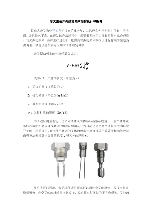
音叉振动频率的计算经验公式为:式中:L:叉体的长度(单位为m)t:叉体的厚度(单位为m)E:杨氏模量(单位为kgf/m2)g:重力加速度(980cm/s2)ρ:叉体材质的密度(kg/m3)为了适应测量现场,使粘附液体或固体容易滴落或脱落,一般叉体外观形状和截面不会设计成规则的矩形,如图是计为自动化公司音叉液位开关和料位开关的三种叉体图。
对这种不规则的叉体的频率计算可以采用等效面积和等效截面得方法来换算出叉体的长度L和叉体的厚度t。
从公式可以看出,音叉标称谐振频率可以通过音叉的厚度、长度变化来微量调整,改变叉体的材料同样能改变。
振动频率与叉长的平方成反比,叉长越长,频率越低;而与叉厚成正比,叉体越薄,振动频率越低,频率变化数据详见表一和表二所示。
长度增加量(△L:mm)12345频率减少量(△F:Hz)12.7567.6长度缩短量(△L:mm)12345频率增加量(△F:Hz)2467.79.6表一:叉体长度值改变,其振动频率改变的量值厚度增加量(△T:mm)0.10.20.30.40.5频率增加量(△F:Hz)3.7710.313.516.7厚度减少量(△T:mm)0.10.20.30.40.5频率减少量(△F:Hz)2.76912.215.5表二:叉体厚度值改变,其振动频率改变的量值除了上述两种调整方法外,选用杨氏模量值E值大的材料,也能提高振动体的振动频率。
上述计算出的音叉振动频率是在自由状态下的谐振频率。
音叉振幅与驱动功率有关,一般频率越高振幅越小,反之亦然。
在振幅不大情况下,音叉自由状态下的谐振频率与空气中的谐振频率接近。
- 1、下载文档前请自行甄别文档内容的完整性,平台不提供额外的编辑、内容补充、找答案等附加服务。
- 2、"仅部分预览"的文档,不可在线预览部分如存在完整性等问题,可反馈申请退款(可完整预览的文档不适用该条件!)。
- 3、如文档侵犯您的权益,请联系客服反馈,我们会尽快为您处理(人工客服工作时间:9:00-18:30)。
音叉液位开关灵敏度高低如何调试
市场上音叉液位开关种类繁多,有的有灵敏度调节,有的没有灵敏度调节。
对于具有灵敏度调节功能的音叉液位开关,灵敏度高低究竟该怎么调试的问题,很多用户不甚了了。
本文以计为Ring-11音叉液位开关为例,为大家介绍一下音叉液位开关灵敏度高低调试的方法,希望对大家更好的应用音叉液位开关有所帮助。
图1 继电器输出方式 图2 二线制输出方式
①密度开关 ② 高低位模式 ③ 指示灯 ④ 接线端子 ⑤ 接地端子
计为Ring-11音叉液位开关的输出方式有继电器和二线制两种,如上图1和图2所示。
图中的①为密度开关,也即灵敏度调节开关,出厂时标注①的开关一般拨动到图示中的向下位置(靠接线端子一侧),也即标注≥0.7g/ cm³的一侧,此时测量液体的密度要大于等于0.7g/ cm³,能适应绝大部分液体的测试;通过控制面板上的密度调节开关可改变Ring-11音叉液位开关的测量灵敏度,使之更好地适应被测液体,当遇到密度特别低的液体如液化石油气时,可将密度开关拨到上档位(即远离接线端子一侧),此时最低测量密度可放宽到≥0.5g/cm³,使得检测更加灵敏,测量的可靠性更高。
以上就是“音叉液位开关灵敏度高低如何调试”的相关介绍,如欲了解更多物位开关(料位开关、液位开关)、物位计(料位计、液位计)等物位测量仪表方面的知识,欢迎关注微信公众号:Jiweimeter 。