PLD脉冲激光沉积简介
磁控溅射法的工作原理
(R, A)n1MnnO3n+1
二、锰氧化物的结构及其庞磁电阻效应
1.钙钛矿锰氧化物基本的晶格
一般泛指的锰氧化物(Manganites)是基于钙钛矿结构来说 的,它的通式可以写为:(R, A)n1MnnO3n+1(其中R 为稀土元素, A 为碱土元素) ,通常也称作Ruddlesden-Popper(RP)相。在 RP化合物中,“n”代表MnO6 八面体顺着晶体[001]方向堆 垛的层数。如图1所示,单层 n = 1 的(R,A)2 MnO4化合物具有 二维的K2NiF4 结构,由一层MnO6八面体层和一层(R/A,O)交替 堆垛组成。n =2的双层(R,A)3Mn2O7和n = 3的三层(R,A)4Mn3O10化合 物分别有两层MnO6 八面体和三层 MnO6八面体与一层 (R/A,O)交 替堆垛组成。n =∞的化合物 (R,A)MnO3 具有无穷层的三维钙钛 矿结构。其中结构为(R,A)Mn2O7和 (R,A)MnO3的部分化合物表现出 CMR效应。
极化度 、电场E、诱导偶极矩m三者之间的关系:
E
拉曼和红外是否活性判别规则: (1) 相互排斥规则: 凡具有对称中心的分子,具
有红外活性(跃迁是允许),则其拉曼是非活性(跃迁是 禁阻)的;反之,若该分子的振动对拉曼是活性的,则 其红外就是非活性的。
层状晶格图形如下
2. CMR效应 CMR效应存在于钙钦矿结构的掺杂锰氧化物中。不
同于GMR和TMR依赖于人工制备的纳米结构,钙钦矿锰 氧化物的CMR效应是大块材料的体效应。由于其磁电 阻值特别巨大,为了区别于金属多层膜中的GMR效应, 人们将这种钙钦矿结构中的磁电阻效应冠之以超大磁 电阻效应(eolossalMagnetoresistanee),简称CMR效 应。CMR的一个显著特征是在磁相变的同时伴随着金 属到绝缘态的转变,并且磁电阻的陡然变化通常发生 在居里点()附近,一旦温度偏离居里点,磁电阻迅速 下降。这种极大的磁电阻效应实际上暗示了锰氧化物 材料中自旋一电荷间存在着强烈的关联性。现在己经 确认,锰氧化物具有电子的强关联特性,其CMR机理, 与铜氧化物的高温超导电性是一样的,是多电子强关 联系统中十分有趣和困难的问题。
脉冲激光沉积法Li-N双受主共掺p型ZnO薄膜的生长及其特性

中图分类号: TN304. 2' 1
文献标识码: A
文章编号: 0253-4177(2007)SO -0322-04
1
引言
ZnO 是一种理想的短波长发光材料, 在光电器 件领域有着巨大的应用潜力. 要实现 ZnO 的光电应
得的. 光源为 KrF 准分子激光器, 采用的 Li 掺杂 ZnO 陶瓷靶 中 Li 的摩尔含量分别为 0, 0. 01% , 0. 1% ,0. 5%和 1. 0% . 生长气氛为高压电离 N, O , 沉积气压为 15Pa . 以不掺杂的 ZnO 薄膜为 n 型层,
膜的电导行为对进一步改进 ZnO 的 p 型电导掺杂 很有意义. 本文采用脉冲激光沉积(PLD) 技术生长
Li-N 双受主共掺杂 ZnO 薄膜, 并研究其电学、 结构 和发光特性.
结果, 所有掺杂 ZnO 均呈 p 型. 单独 N 掺杂 ZnO (ZnO:N) 薄膜也呈 p 型, 但其电阻率比较高. 当薄 膜中引人少量的受主 Li 时, 型电导性能大大改 p
C ar r ier L i co nt e nt /at . %
ZnO:(Li,N) 补 妇 「 的 u 。 l u l
0.1at .% L i,N
l .Oat .% L i
Resistivity Hall mobility ( / 0 恤 ) (cmz/ ( V s) )
Car ri善, 电阻率降低了一到两个数量级. 但当 Li 的含量 过高时, 型电导性能又变差. 这是因为过量的 Li p 容易形成 Li 间隙施主缺陷[7.e1. 实验得出优化的靶 E 材 Li 含量为 0. 1% , 所得样品电阻率最低为 3. 990 cm , 载流子浓度为 9. 12 x 10" cm- 3. Li-N 双受主 共掺杂 p 型 ZnO 薄膜的突出优点在于其电学稳定
薄膜沉积物理方法超强总结
电弧加热蒸发装置示意图
真空蒸发沉积
三、电弧放电加热蒸发:
3、主要优点: 与电子束蒸发类似,可避免加热体/坩锅材料蒸发污染薄膜; ❖加热温度高,可沉积难熔金属和石墨 (蒸发源即电极,须导 电); 设备远比电子束蒸发简单,成本较低。
4、主要缺点: 电弧放电会产生 m大小的颗粒飞溅,影响薄膜的均匀性和质 量。
薄膜制备物理方法总结
蒸发(Evapor)
Physical
Vapor
Deposition
溅射(Sputtering ) 离化PVD(离子镀、IBAD、IBD等)
的物 理方 法
外延技术 Epitaxy
分子束外延 (MBE,Molecular Beam Epitaxy 液相外延 (LPE,Liquid Phase Epitaxy ) 热壁外延 (HWE,Hot Wall Epitaxy )
轰击坩埚
电子束蒸发装置 示意图
薄膜沉积
采用电场 (5~10 kV) 加速获得高能电子束。 磁场偏转法的使用可以避免灯丝材料的蒸发 对于沉积过程可能造成的污染。
真空蒸发沉积
二、电子束蒸发:
➢ 应用场合:适用于高纯度(高真空度)、高熔点、易污染 薄膜材料的沉积。
➢ 优点: 加热温度高,可蒸发任何材料; 可避免来自坩锅、加热体和支撑部件的污染;
5、主要应用:沉积高熔点难熔金属及其化合物薄膜、碳材料薄膜.
真空蒸发沉积
四,脉冲激光沉积
PLD也被称为脉冲激光烧蚀:pulsed laser ablation,PLA.
1,原理: 将脉冲激光器产生的高功率脉冲激光聚焦于靶表面,
使其表面产生高温及烧蚀,并进一步产生高温高压等离子 体,等离子体定向局域膨胀,在衬底上沉积成膜。真空 度~10-6 Pa,可实现multilayer的沉积
脉冲激光烧蚀固体_从正常蒸发转变到相爆炸_刘丹

2008年8月第25卷第8期Aug.2008Vo1.25No.8湖北第二师范学院学报Journal of Hubei University of Education脉冲激光沉积法(PLD )是20世纪80年代发展起来的一种新型的薄膜制备技术。
人们利用PLD 技术已经成功制备了许多铁电薄膜,光学光电薄膜,半导体金属超硬材料等功能薄膜,实验上已取得了很大进展,但是PLD 机理的研究却滞后于实验的研究,特别是对于高能纳秒级脉冲激光烧蚀的情况。
对于脉冲激光烧蚀金属和类金属材料,将会发生三种过程,即:正常蒸发,正常沸腾以及相爆炸。
对于纳秒级脉冲激光烧蚀情况,随着激光能量密度的增加,当材料达到临界点时,正常蒸发将被相爆炸所代替。
此处,我们首先给出了正常蒸发情况下的烧蚀模型,然后讨论了亚表面加热及沸腾现象。
1正常蒸发情况下的烧蚀模型当高能短脉冲激光(激光功率密度高于108W cm -2)烧蚀材料时,靶材表面吸收激光能量,温度迅速上升,达到沸点,气化现象突然加剧,随着温度的继续上升,蒸气吸收激光能量完成电离,继而形成高温高密度的等离子体,等离子体将吸收激光能量,阻碍部分激光达到靶材上。
[1][2]基于此,给出如下烧蚀模型。
考虑一维热传导,热传导方程由下式表示:(1)其中,ρ为靶材的密度,C P ,λ和αb 分别为热容,热导率和靶材的吸收系数;R (T s )是考虑随靶材表面温度T s 变化的反射率。
u (t )是靶材表面的后退速度,它由克劳修斯—克拉伯龙方程给出:(2)其中,L 是靶材的气化热,T b 是对应于蒸气压P b 时的沸点。
此处的I (t )是指达到靶材表面的激光功率密度,它由下式表示:(3)其中I 0(t )是指入射的激光功率密度,∧(t )是指等离子体的总光学厚度,α(n p ,T p )是指依赖于等离子体密度及温度而变化的等离子体的吸收系数。
等离子体的总光学厚度(4)其中,T v 是蒸发温度,是烧蚀深度,E a (t )是被靶材吸收的激光能量密度,γ是绝热指数,a ,b 是根据实验数据拟和的自由参数。
常见镀膜方法调查

常见镀膜方法1、脉冲激光沉积(PLD)PLD原理:脉冲激光沉积法(PLD法)是一种全新的工艺,但是具有很大的潜力。
PLD法的原理是利用激光对物体进行轰击后被轰击出来的物质,将被轰击出来的物质沉淀在不同的衬底上,并得到沉淀或者薄膜的一种手段。
PLD优点:1、与其他工艺相比,作为一种全新的成膜技术,它的生长参数独立可调,并可精确控制化学计量比,从而易于实现超薄薄膜的生长和多层膜的制备,生长的薄膜结晶性能较好,膜的平整度也较高。
2、除非是极少数对该种激光而言是透明的材料,几乎所有的材料都可用PLD法制膜,可见PLD法可制膜种类之多。
3、PLD技术的成膜效率高,能够进行批量生产。
PLD缺点:1、在镀膜过程中,薄膜会被沉积在薄膜上的等离子体管中产生的微粒、气态原子和分子降低质量,采取一定的措施后也不能完全消除。
2、在控制掺杂、生长平滑的多层膜等方面PLD生长都比较困难,因此进一步提高薄膜的质量会比较困难。
3、PLD法镀膜厚度不够均匀,等离子体羽辉中的粒子速率在不同的方向有所不同,使粒子分布不均。
4、等离子局域分布难以形成大面积的薄膜。
应用及前景:有望在高质量ZnO薄膜的研究和生产中得到广泛的应用。
PLD法将在半导体薄膜、超晶格、超导、生物涂层等功能薄膜的制备方面发挥重要的作用;并能加快薄膜生长机理的研究和提高薄膜的应用水平,加速材料科学和凝聚态物理学的研究进程。
同时也为新型薄膜的制备提供了一种可行的方法。
2、化学气相沉积 (CVD)CVD原理:它是一种或几种气态反应物在衬底表面发生化学反应而沉积成膜的工艺。
反应物质是由金属载体化合物蒸汽和气体载体所构成,沉积在衬底上形成金属氧化物薄膜,衬底表面上发生的这种化学反应通常包括金属源材料的热分解和原位氧化。
优点:1、 CVD 技术所形成的膜层致密且均匀, 膜层与基体的结合牢固, 薄膜成分易控, 沉积速度快, 膜层质量也很稳定,某些特殊膜层还具有优异的光学、热学和电学性能, 因而可以实现批量生产。
【国家自然科学基金】_脉冲激光沉积技术_基金支持热词逐年推荐_【万方软件创新助手】_20140730
推荐指数 14 3 3 2 2 2 2 2 2 2 2 1 1 1 1 1 1 1 1 1 1 1 1 1 1 1 1 1 1 1 1 1 1 1 1 1 1 1 1 1 1 1 1 1 1 1 1 1 1 1 1 1
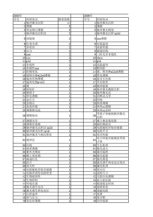
2009年 序号 1 2 3 4 5 6 7 8 9 10 11 12 13 14 15 16 17 18 19 20 21 22 23 24 25 26 27 28 29 30 31 32 33 34 35 36 37 38 39 40 41 42 43 44 45 46 47 48 49 50 51 52
科研热词 脉冲激光沉积 薄膜 类金刚石薄膜 脉冲激光沉积法 深能级 拉曼光谱 异质结 应力 zno sic pld 非线性 非极性zno 阳极氧化 镱铒共掺al2o3薄膜 锰氧化物薄膜 锰氧化物p-n结 锗 锐钛矿 铜离子 铁电薄膜 金红石 金刚石 表面形貌 薄膜锂电池 薄膜取向 薄膜光学 薄膜传感器 脉冲激光沉积法(pld) 脉冲激光沉积(pld) 脉冲激光气相沉积法 缓冲层 结构 纳米薄膜 紫外光吸收 稀土氧化物 磁通钉扎 硅片 相关性 电阻随机存取存储器 电脉冲诱发电阻转变 生物相容性 生物材料 环境压强 激光感生电压 激光感生热电电压 沉积速率 氧气压力 氧化锌薄膜 氧化锌 椭偏法 材料
科研热词 脉冲激光沉积 x射线衍射 铁电薄膜 脉冲激光烧蚀 沉积温度 光致发光 xrd 高介电常数栅介质 马赫-曾德干涉 饱和磁化强度 面外磁性能 阳极氧化 阈值温度 锡酸盐 铁酸铋薄膜 铁电电容器 金刚石/硅基底 退火 薄膜生长取向 薄膜 蓝移 蒙特-卡罗模拟 脉冲激光沉积(pld) 能量沉积 缓冲层 结合强度 组分和掺杂 纳米粉体 纳米si晶粒 硼碳氮薄膜 矫顽场 电路模拟 电爆炸金属丝 电极 环境气体 烧蚀粒子 激光技术 激光感生电压效应 激光感生热电电压信号 激光冲击划痕 深能级缺陷 氧空位 氧气压强 气流 气体种类 材料制备 晶须 晶粒界 时空分布 成核势垒 成分 快速退火
【国家自然科学基金】_pulsed laser deposition_期刊发文热词逐年推荐_20140801

科研热词 推荐指数 脉冲激光沉积 11 薄膜 3 脉冲激光沉积法 3 光致发光 3 锂离子电池 2 表面形貌 2 结构 2 氧化锌 2 zno 2 pld 2 镱铒共掺al2o3薄膜 1 锗 1 锐钛矿 1 金红石 1 金刚石 1 衬底温度 1 脉冲激光沉积法(pld) 1 脉冲激光沉积方法 1 脉冲激光沉积(pld) 1 脉冲激光气相沉积法 1 缓冲层 1 结晶度 1 纳米薄膜 1 紫外脉冲激光极化 1 类金刚石薄膜 1 磁性 1 硫化锗–硫化稼–硫化镉非晶薄膜1 环境压强 1 激光感生热电电压 1 深能级 1 沉积速率 1 氧气压力 1 氧化锌薄膜 1 材料 1 晶格参数 1 晶体结构 1 无机非金属材料 1 异质结 1 应力 1 反射式高能电子衍射 1 光波导 1 光学特性 1 光学性质 1 二阶非线性光学效应 1 zno薄膜 1 zn1-xcoxo稀磁半导体 1 x射线衍射 1 x射线吸收精细结构谱 1 xanes 1 tio2薄膜 1 srtio3薄膜 1 srnb0.2ti0.8o3薄膜 1
53 54 55 56 57 58 59 60 61 62 63 64 65 66 67
光学常数 低热膨胀 α 轴晶粒 zrw2o8 zro2 ybco x射线衍射谱 x射线衍射 pt薄膜 pt/bst界面层 licoo2薄膜 licoo2 la0.67sr来自.33mno3 ge bst薄膜
推荐指数 7 4 3 2 2 2 2 2 2 1 1 1 1 1 1 1 1 1 1 1 1 1 1 1 1 1 1 1 1 1 1 1 1 1 1 1 1 1 1 1 1 1 1 1 1 1 1 1 1 1 1 1
2008年 序号 1 2 3 4 5 6 7 8 9 10 11 12 13 14 15 16 17 18 19 20 21 22 23 24 25 26 27 28 29 30 31 32 33 34 35 36 37 38 39 40 41 42 43 44 45 46 47 48 49 50 51 52
脉冲激光沉积技术

脉冲激光沉积技术
王萍;解廷月;李海
【期刊名称】《山西大同大学学报(自然科学版)》
【年(卷),期】2008(024)004
【摘要】薄膜技术作为一种有效的手段为材料的集成和器件的制备提供了坚实的基础.本文主要介绍脉冲激光沉积技术的基本原理、特点、优点和缺点.该方法尤其适合用来生长多组分、化学结构复杂的过渡金属氧化物薄膜.
【总页数】4页(P19-22)
【作者】王萍;解廷月;李海
【作者单位】山西大同大学物理与电子科学学院,山西,大同,037009;山西大同大学物理与电子科学学院,山西,大同,037009;山西大同大学物理与电子科学学院,山西,大同,037009
【正文语种】中文
【中图分类】TN24
【相关文献】
1.脉冲激光沉积PLD技术及其应用 [J], 吕珂
2.脉冲激光沉积技术制备超导铌薄膜及其特性研究 [J], 彭明娣;卢维尔;夏洋;王桐;赵丽莉;李楠
3.脉冲激光沉积技术制备的钪型阴极的发射性能 [J], 彭真;阴生毅;郑强;王欣欣;王宇;李阳
4.利用脉冲激光沉积技术制备镍纳米颗粒及其生长过程中的应变场模拟 [J], 袁彩
雷;张求龙;江子雄
5.用脉冲激光沉积技术制备与分析嵌入非晶SiO2中的锗纳米粒子 [J], 吴闰生;王伟
因版权原因,仅展示原文概要,查看原文内容请购买。
- 1、下载文档前请自行甄别文档内容的完整性,平台不提供额外的编辑、内容补充、找答案等附加服务。
- 2、"仅部分预览"的文档,不可在线预览部分如存在完整性等问题,可反馈申请退款(可完整预览的文档不适用该条件!)。
- 3、如文档侵犯您的权益,请联系客服反馈,我们会尽快为您处理(人工客服工作时间:9:00-18:30)。
英文原文:CHAPTER 1Pulsed Laser Deposition of Complex Materials: Progress TowardsApplicationsDAVID P. NORTONUniversity of Florida, Department of Materials Science and Engineering, Gainesville, Florida1.1 INTRODUCTIONIn experimental science, it is a rare thing for a newly discovered (or rediscovered) synthesis technique to immediately deliver both enhanced performance and simplicity in use in a field of accelerating interest. Nevertheless, such was the case with the rediscovery of pulsed laser deposition(PLD) in the late 1980s. The use of a pulsed laser as a directed energy source for evaporative film growth has been explored since the discovery of lasers [Hass and Ramsey, 1969; Smith and Turner, 1965]. Initial activities were limited in scope and involved both continuous-wave (cw) and pulsed lasers. The first experiments in pulsed laser deposition were carried out in the 1960s; limited efforts continued into the 1970s and 1980s. Then, in the late 1980s, pulsed laser deposition was popularized as a fast and reproducible oxide film growth technique through its success in growing in situ epitaxial high-temperature superconducting films [Inam et al., 1988]. The challenges for in situ growth of high-temperature superconducting oxide thin films were obvious. The compounds required multiple cations with diverse evaporative properties that had to be delivered in the correct stoichiometry in order to realize a superconducting film. Simultaneously, the material was an oxide, requiring an oxidizing ambient during growth. Pulsed laser deposition had several characteristics that made it remarkably competitive in the complex oxide thin-film research arena as compared to other film growth techniques. These principle attractive features were stoichiometric transfer, excited oxidizing species, and simplicity in initial setup and in the investigation of arbitratry oxide compounds. One could rapidly investigate thin-film deposition of nearly any oxide compound regardless of the complexity of the crystal chemistry. Significant development of pulsed laser deposition has continued and over the past 15 years, PLD has evolved from an academic curiousity into a broadly applicable technique for thin-film deposition research [Saenger, 1993; Kaczmarek, 1997; Willmott and Huber, 2000; Dubowski, 1988; Dieleman et al., 1992]. Today, PLD is used in the deposition of insulators, semiconductors, metals, polymers, and even biological materials. Few material synthesis techniques have enjoyed such rapid and widespread penetration into research and application venues.Pulsed Laser Deposition of Thin Films: Applications-Led Growth of Functional MaterialsEdited by Robert Eason Copyright # 2007 John Wiley & Sons, Inc.34 PULSED LASER DEPOSITION OF COMPLEX MATERIALS1.2 WHAT IS PLD?The applicability and acceptance of pulsed laser deposition in thin-film research rests largely in its simplicity in implementation. Pulsed laser deposition is a physical vapor deposition process, carried out in a vacuum system,that shares some process characteristics common with molecular beam epitaxy and some with sputter deposition. In PLD, shown schematically in Figure 1.1, a pulsed laser is focused onto a target of the material to be deposited. For sufficiently high laser energy density, each laser pulse vaporizes or ablates a small amount of the material creating a plasma plume. The ablated material is ejected from the target in a highly forward-directed plume. The ablation plume provides the material flux for film growth. For multicomponent inorganics, PLD has proven remarkably effective at yielding epitaxial films. In this case, ablation conditions are chosen such that the ablation plume consists primarily of atomic, diatomic, and other low-mass species. This is typically achieved by selecting an ultraviolet (UV) laser wavelength and nanosecond pulse width that is strongly absorbed by a small volume of the target material. Laser absorption by the ejected material creates a plasma. For the deposition of macromolecular organic materials, conditions can be chosen whereby absorption is over a larger volume with little laser absorption in the plume. This permits a large fraction of the molecular material to be ablated intact. For polymeric materials,transfer of intact polymer chains has been demonstrated. For even ‘‘softer’’materials in which the direct absorption by the laser would be destructive to molecular functionality, the formation of composite ablation targets consisting of the soft component embedded in an optically absorbing matrix has been investigated (see, e.g., Chapter 3).Several features make PLD particularly attractive for complex material film growth. These include stoichiometric transfer of material from the target, generation of energetic species,hyperthermal reaction between the ablated cations and the background gas in the ablation plasma,and compatibility with background pressures ranging from ultrahigh vacuum (UHV) to 1 Torr. Multication films can be deposited with PLD using single, stoichiometric targets of the material of interest, or with multiple targets for each element. With PLD, the thickness distribution from aFigure 1.1 Schematic of the PLD process.WHAT IS PLD? 55 stationary plume is quite nonuniform due to the highly forward-directed nature of the ablation plume. To first order, the distribution of material deposited from the ablation plume is symmetric with respect to the target surface normal and can be described in terms of a cos nðyÞ distribution,where n can vary from ~4–30. However, raster scanning of the ablation beam over the target and/or rotating the substrate can produce uniform film coverage over large areas, and this topic is covered in Chapter 9.One of the most important and enabling characteristics in PLD is the ability to realize stoichiometric transfer of ablated material from multication targets for many materials. This arises from the nonequilibrium nature of the ablation process itself due to absorption of high laser energy density by a small volume of material. For low laser fluence and/or low absorption at the laser wavelength, the laser pulse would simply heat the target, with ejected flux due to thermal evaporation of target species. In this case, the evaporative flux from a multicomponent target would be determined by the vapor pressures of the constituents. As the laser fluence is increased, an ablation threshold is reached where laser energy absorption is higher than that needed for evaporation. The ablation threshold is dependent on the absorption coefficient of the material and is thus wavelength dependent.At still higher fluences, absorption by the ablated species occurs, resulting in the formation of a plasma at the target surface. With appropriate choice of ablation wavelength and absorbing target material, high-energy densities are absorbed by a small volume of material, resulting in vaporization that is not dependent on the vapor pressures of the constituent cations.In pulsed-laser deposition, a background gas is often introduced that serves two purposes. First, the formation of multication thin-film materials often requires a reactive species (e.g., molecular oxygen for oxides) as a component of the flux. The amount of reactant gas required for phase formation will depend on the thermodynamic stability of the desired phase. Interaction of ablated species with the background gas often produces molecular species in the ablation plume. These species facilitate multication phase formation. In addition to actively participating in the chemistry of film growth, the background gas can also be used to reduce the kinetic energies of the ablated species. Time-resolved spectroscopy studies of ablation plume expansion have shown that kinetic energies on the order of several hundred electron volts can be observed [Chen et al., 1996]. A background gas can moderate the plume energies to much less than 1 eV. The vapor formed by laser ablation compresses the surrounding background gas resulting in the formation of a shock wave.Interaction with the ambient gas slows the ablation plume expansion.For the deposition of multication materials, target selection can have significant impact on film growth properties, including particulate density, epitaxy, phase formation, and deposition rate. As a minimum requirement, ablation requires a target material possessing a high optical absorption coefficient at the selected laser wavelength. In general, the phase of the target does not need to be the same as that of the desired film. Only the cation stoichiometry need be identical to that of the films, assuming stoichiometric transfer and negligible evaporation from the film surface. For ceramic targets, one prefers target materials that are highly dense, as this will reduce particulate formation during the ablation process. As an alternative to polycrystalline ceramics, the use of single crystals as ablation targets has been investigated and shown to be effective in further reduction of droplet densities [Li et al., 1998]. The exception to this is wide bandgap insulators, such as Al2O3, where insufficient optical absorption makes single crystals unattractive as ablation targets. For soft materials, including biological materials, the target might be the material of interest or the material embedded in a matrix of an optically absorbing substance that does not deposit but yields an efficient ablation process.An alternative to ceramic or single-crystal targets is reactive PLD where the targets consist of the constituent cations, while the anion is supplied by the background gas. In general, the ablation process is less efficient for metal cations due to higher reflectivity and thermal conductivity. In addition, films deposited via ablation of metal targets can exhibit high particulate densities due to the ejection of molten droplets: for some systems, this problem can be addressed by using liquid metal targets. For some specific multication systems, metal targets have useful advantages. For the growth of multication films in which cation purity is an important issue, metals are often available with the6 PULSED LASER DEPOSITION OF COMPLEX MATERIALShighest purity. In addition, for insulators that possess particularly wide optical bandgaps, such as MgO, the ablation efficiency from ceramic or single-crystal targets is low for commercially available pulsed laser wavelengths.One also needs to consider the laser wavelength used for ablation. Efficient ablation of the target material requires the nonequilibrium excitation of the ablated volume to temperatures well above that required for evaporation. This generally requires the laser pulse to be short in duration, high in energy density, and highly absorbed by the target material. For ceramic targets, this is most easily achieved via the use of short wavelength lasers operating in the ultraviolet. High-energy ultraviolet laser pulses can be readily provided via excimer lasers or frequency-tripled or quadrupled Nd : YAG solid-state lasers. In some cases, a more efficient source is an infrared laser whose energy corresponds to a vibrational mode of the ablation target material [Bubb et al., 2002].In laser ablation, each ablation pulse will typically provide material sufficient for the deposition of only a submonolayer of the desired phase. The amount of film growth per laser pulse will depend on multiple factors, including target –substrate separation, background gas pressure and laser spot size, and laser energy density. Under typical conditions, the deposition rate per laser pulse can range from 0.001 to 1 A˚ per pulse. As such, PLD enables laser shot-to-shot control of the deposition process that is ideal for multilayer and interface formation where submonolayer control is needed. This degree of control can be seen from the in situ surface studies using reflection high-energy electron diffraction (RHEED), as discussed in detail in Chapter 8[Bozovic and Eckstein, 1995; Foxon, 1991]. RHEED provides a means of determining the crystallinity and smoothness of a surface, and oscillations in the intensity of diffraction spots during film growth correlate to the atomic layer-by-layer growth of the material. Figure1.2 shows the specular intensity of RHEED data for an epitaxial oxide film being deposited by PLD [Rijnders et al., 2000]. Two types of time-0 350 Time (s)0 40 Time (s) Figure 1.2 The specular RHEED intensity during PLD at 1 Hz (T ¼ 750o C, p O 2 ¼ 3 Pa). The insets give enlarged intensity after one laser pulse at 0.9 and 0.95 unit-cell layer coverage y. Also shown is (a) intensity variations of the specular reflection during PLD at 1 Hz and (b) interval deposition using the (b) t=0.45 s t=0.25 s(a)I n t e n s i t y (a r b i t r a r y u n i t s )WHAT IS PLD? 75 laser repetition rateof 10 Hz (T ¼ 800o C, p O2 ¼ 10 Pa) [Rijnders et al., 2000].8 PULSED LASER DEPOSITION OF COMPLEX MATERIALSdependent structure can be observed in the RHEED intensity plot. First, the oscillations observed in the intensity in Figure 1.2a represent the deposition of single unit cells of the oxide film. Specular RHEED intensity is dependent on the spatial coherence of the surface atoms. As layer-by-layer growth cycles through submonolayer coverage of the surface, RHEED intensity decreases, while for completed layers, the intensity is high. The oscillations seen in Figure 1.2a indicate that unit cell by unit cell growth on an atomically flat surface is occurring. The superimposed time-dependent substructure in the RHEED intensity seen in Figure 1.2b corresponds to surface redistribution of ablation plume species that have condensed on the surface from an individual ablation pulse. The time dependence of this structure yields insight into the nucleation and growth of the film at the submonolayer level for the arrival of each ablation plume.For multicomponent film growth, most of the limitations identified early in the development of PLD have been allieviated. A key development for the utilization of pulsed laser deposition for applications in industry has been the realization of schemes by which large area substrates can be effectively coated. The dynamics of the laser ablation process result in a highly focused plume of material ejected from the target. While this leads to a deposition efficiency on the order of 70%, it also results in a significant variation in deposition rate over distances on the order of a few centimeters. For uniform film thickness over large areas, manipulation of the plume –substrate positioning is required. Several approaches have been implemented to overcome this limitation, the most straightforward being to combine substrate rotation with rastering of the ablation beam over a large ablation target. This will, to first order, provide a means for covering large area substrates. However, one must take into account the decrease in plume energies and change in plume stoichiometry as one moves to the edge of the plume region.In pulsed laser deposition, the kinetic energies of ions and neutral species in the ablation plume can range from a few tenths to as high as several hundred electron volts. These energies are sufficient to modify the stress state of films through defect formation as has been documented for ion-beam- assisted approaches. The most common consequence of allowing deposition from an unabated energetic plume is the introduction of compressive stress. The origin of compressive stress due to energetic bombardment is associated with subsurface damage from the impinging energetic species, as schematically illustrated in Figure 1.3, leading to interstitial defects [Norton et al., 1999]. In this500Energetic atoms from ablation plume impinge on surface400300200100660 nm CeO 2 on 110 µm Si Curvature due to plume- induced compressive stress Collisions induce subsurface implantation to interstitials 00 200 400 600 800 1000 Scan distance (µm)Interstitials induce compressivestress in growing filmFigure 1.3 Schematic of plume-induced stress in PLD-deposited films.Z (n m )WHAT IS PLD? 95 case, the energetic depositing atoms displace underlying atoms in the film, resulting in atoms displaced to interstitial sites. Stress on the order of gigapascals has been observed. For thin substrates, this compressive stress can be sufficient to induce bowing of the structure as indicated in Figure 1.3 for CeO2 on a thin Si wafer. The kinetic energy necessary for the onset of recoil implantation of surface atoms into the film interior through bombardment is material dependent but is often observed for ion bombarding energies of a few electron volts or greater [Muller, 1989]. For oxides, the energetic bombarding cations can also preferentially sputter oxygen atoms from the surface, resulting in films that are oxygen deficient. The kinetic energy of ablated species is largely dependent on laser energy and gas-phase collisions. Fortunately, the use of a background gas to thermalize the plume is usually effective in eliminating this problem.Another potential issue with PLD is the ejection of micron-size particles in the ablation process. This is often observed when the penetration depth of the laser pulse into the target material is large.If these particles are deposited onto the substrate, they present obvious problems in the formation of multilayer device structures. The use of highly dense ablation targets and ablation wavelengths that are strongly absorbed by the target tends to reduce or eliminate particle formation. Mechanical techniques have been developed to reduce particle density in the event that target density and/or laser wavelength optimization fails to eliminate particulates. These include velocity filters [Pechen et al.,1995], off-axis laser deposition [Holzapfel et al., 1992], and line-of-sight shadow masks [Trajanovic et al., 1997]. Cross-beam techniques have also been considered as described in Chapter 6.In addition to particles ejected from the ablation targets, one can also observe nanoparticles that form in the gas phase when the background pressure is sufficiently high for heterogeneous particle nucleation. These particles can become embedded in a depositing film. Figure 1.4 shows a cross- section transmission electron microscopy image of a CeO2 film with the initial growth occurring at high pressure while the remaining film was grown at low pressure. CeO2 nanoparticles are clearly evident in the epitaxial CeO2 thin-film matrix [Norton et al., 1998]. In particular, the nanoparticles,with diameters ranging from 10 to 40 nm, are seen in the layer formed by ablating a CeO2 target in a hydrogen–argon background gas at a pressure of 200 mTorr. In contrast, the upper part of the CeO2film is devoid of nanoparticles and was deposited in a background pressure of 10-5 Torr where gas-phase collisions are minimal. While the formation of nanoparticles is generally undesirable for thin-film growth, this heterogeneous gas-phase nucleation has been intentionally exploited in the synthesis and study of nanomaterials, including oxides and semiconductors.While stoichiometric transfer of target composition is readily achieved for nearly every material,this does not ensure stoichiometric film growth at elevated temperature if any of the cation species possess high vapor pressures. Specific cations for which the sticking coefficient is an issue include K, Li, Na, Tl, Mg, Pb, Cd, and Zn. We consider as an example ZnGa2O4 [Lee et al., 1999], which is a wide bandgap semiconducting spinel that is of interest as a phosphor material. Films deposited using a stoichiometric single ZnGa2O4 target will show significant Zn deficiency for elevated deposition temperatures due to the higher vapor pressure of Zn relative to that of Ga. Figure 1.5 shows theFigure 1.4 Cross-section TEM image of a CeO2 film grown at high and low pressure, with CeO2 nanoparticles forming at the high background pressure.10 PULSED LASER DEPOSITION OF COMPLEX MATERIALSTarget PO2 P tot(mTorr)Single Mosaic Target400 450 500 550 600 650 700 750Substrate temperature (C)Figure 1.5 Plot of the Zn/Ga ratio for ZnGa2O4 films deposited using mosaic ablation targets.Zn/Ga ratio for films deposited at several different background pressures. Note that stoichiometric ZnGa2O4 corresponds to a Zn/Ga ratio of 0.5. Using a stoichiometric target, a Zn/Ga ratio as low as0.12 is observed for films deposited at 500o C. The optimal growth temperature, on the order of 600 –700o C, yields even greater deficiency in Zn content. One means of compensating for the loss of the volatile species in the films is to use a mosaic target consisting of the desired material and an additional region rich in the volatile component. Figure 1.5 compares the results for ZnGa2O4 films deposited with a single ZnGa2O4 target versus mosaic ZnGa2O4/ZnO targets. Stoichiometric ZnGa2O4 films required a target mosaic of 50% ZnGa2O4, 50% ZnO. The additional ZnO flux provides a means of overcoming the disparity in cation vapor pressure. Note that the stoichiometry also depended on oxygen partial pressure, which likely reflects the difference in vapor pressure for Zn as compared to ZnO.1.3 WHERE IS PULSED LASER DEPOSITION BEING APPLIED?Given the attractive characteristics of pulsed laser deposition in the synthesis of multicomponent thin-film materials, a number of applications are being actively pursued using this technique. In some cases, the application focuses on the synthesis of a thin-film material or structure. In other cases, the research has targeted the development of specific devices. It is interesting to consider specific structures, devices, and applications for which PLD has been successfully applied. Many of these topics are discussed in more detail in later chapters in Parts 3 and 4.1.3.1 Complex Oxide Film GrowthIn the growth of crystalline oxides, PLD has proven to be most effective. The growth of complex oxides requires the delivery of a growth flux with the correct stoichiometry in an oxidizing ambient that is favorable for the desired phase formation. The utility of pulsed laser deposition in reproducing target stoichiometry has been demonstrated for a number of multication oxides. Early success in realizing stoichiometric YBa2Cu3O7 clearly delineated this advantage for pulsed laser deposition. In recent years, even more complex crystal structures have been successfully grown using this approach. Consider, for example, the growth of the Y-type magnetoplumbite Ba2Co2Fe12O22compound. This material is a ferromagnetic oxide of potential interest in thin-film magnetic device applications [Sudakar et al., 2003]. The epitaxial growth of Ba2Co2Fe12O22 is challenging as it possesses a remarkably complex crystal structure as illustrated in Figure 1.6a. The unit cell possesses a huge lattice parameter of 43.5 A˚. Despite the complexity of the crystal structure, the epitaxial growth of Ba2Co2Fe12O22 has been realized via pulsed laser deposition [Ohkubo et al., 2003]. Figure 1.6b and 1.6c show the X-ray diffraction data for an epitaxial film, along with theI IIZnGa2O4ZnOZn/GaSingle 24 60Mosaic I 24 60Mosaic II 24 60Mosaic II 45 60Mosaic II 60 60Mosaic II 75 100WHERE IS PULSED LASER DEPOSITION BEING APPLIED?9Figure 1.6 Crystal structure, X-ray diffraction data, and TEM image of a Ba2Co2Fe12O22 film grown by PLD [Ohkubo et al., 2003].cross-sectional transmission electron microscopy (TEM) image. It should be noted that this result was obtained using a combinatorial synthesis approach in which multiple process parameters(composition, temperature) are explored in parallel through the use of combinatorial arrays or compositional spread techniques. Pulsed laser deposition has proven to be easily adaptable to combinatorial techniques for thin-film research. The ability to grow epitaxial, multication complex inorganic thin films has been, and continues to be, one of the enabling strengths of PLD.1.3.2 Epitaxial Interface and Superlattice FormationDevelopments in oxide PLD film growth have provided remarkable opportunities in the synthesis of epitaxial heterostructures and superlattices [Yilmaz et al., 1991; Fernandez et al., 1998; Chang et al., 1999; Smolenskii et al., 1984; Xu et al., 2000]. Superlattices of oxides, such as the (001) KNbO3/KTaO3 perovskite structure shown in Figure 1.7, have been realized for a number of material systems, with individual layers as thin as a single unit cell [Christen et al., 1996, 1998; Specht et al.,1998]. Excellent film flatness and crystallinity are evidenced in these films, and the interfaces can beFigure 1.7 Cross-section Z-contrast STEM image of a KTaO3/KNbO3 superlattice structure grown by pulsed laser deposition.10 PULSED LASER DEPOSITION OF COMPLEX MATERIALSFigure 1.8 Cross-section Z-contract STEM image of a CeO2/Ge epitaxial interface fabricated using PLD. compositionally sharp on an atomic scale as seen in Figure 1.7. In the formation of atomically abrupt interfaces and superlattice structures, PLD is competitive with other film growth techniques,including molecular orbital chemical vapor deposition (MOCVD) and molecular beam epitaxy(MBE). The formation of epitaxial oxide superlattices has been used to investigate the effects of reduced dimensionality on a number of phenomena. Superconductivity in single unit cell YBa2Cu3O7 layers was first demonstrated using PLD. Low dimensionality behavior has been investigated for ferroelectric and magnetic oxides.Pulsed laser deposition also yields the opportunity to create atomically abrupt interfaces between materials that are chemically dissimilar, including epitaxial metal–oxide and semiconductor–oxide structures. A key factor in the formation of atomically abrupt interfaces between oxide films and nonoxide surfaces is to identify conditions where undesirable interfacial reactions are minimal yet compatible with oxide epitaxy. Laser ablation film growth is particularly well suited for nucleation in a reactive environment since it is compatible with a large range of background pressures. For example, a hydrogen-assisted nucleation approach has been used to grow atomically abrupt,epitaxial CeO2/Ge interfaces [Norton et al., 2000]. During the initial nucleation of CeO2 on Ge, the hydrogen partial pressure and substrate temperature are chosen such that the native oxide, GeO2, is thermodynamically unstable, and under these conditions, the epitaxial growth of an oxide can be achieved on the Ge surface without interference from native oxides. The deposited oxide material must itself be thermodynamically stable under the conditions used during nucleation, and epitaxy will be determined by the chemistry and structure of the two materials. For CeO2 nucleated on (001) Ge in hydrogen gas using pulsed laser deposition, the film can be epitaxial with an interface that is atomically abrupt as is evident in the cross-section Z-contrast scanning transmission electron microscopy image shown in Figure 1.8. A similar approach has been used to form epitaxial interfaces between various oxides and metals (e.g., Ni and Ni alloys), as well as compound semiconductors, including InP. The latter is of interest as it provides a means of integrating electronic oxides with photonic and microwave electronics.。