W221W204W211 CAN BUS
CAN2.0 规范

Bit NO.
1 2
3 4
5 6
7
9
11 10 12
13 14
15
S 8
S 16
17 18
19
S 20
21 22
23
广州周立功单片机发展有限公司
19
错误类型
位错误( 位错误(Bit Error):发送的位值和总线监视的位值不相 Error):发送的位值和总线监视的位值不相 符合时,检测到一个位错误; 填充错误( 填充错误(Stuff Error):如果在使用位填充编码的位流 Error):如果在使用位填充编码的位流 中,出现了第六个连续相同的位电平,将检测到一个位填 充错误; 形式错误 (Frame Error):当一个固定形式的位场含有 Error):当一个固定形式的位场含有 一个或多个非法位时,将检测到一个形式错误; 应答错误 (Acknowledgment Error ):在应答间隙( ):在应答间隙( ACK SLOT)所监视的位不为“显性”,则会检测到一个 SLOT) 应答错误; CRC 错误(CRC Error):如果接收器的CRC结果和发送 错误( Error):如果接收器的CRC结果和发送 器的CRC结果不同,将检测到一个CRC错误。 器的CRC结果不同,将检测到一个CRC错误。
CANCAN-bus 2.0A/B规范 2.0A/B规范
Version 1.00版 1.00版
2004年 2004年7月
广州周立功单片机发展有限公司
1
CAN-bus简介 CAN-bus简介
控制器局域网CAN( 控制器局域网CAN(Controller Area Network),最初是 Network),最初是 由德国Bosch公司设计的,应用于汽车的监测和控制。 由德国Bosch公司设计的,应用于汽车的监测和控制。 作为一种技术先进、可靠性高、功能完善、成本合理的远程 网络通讯控制方式,CAN-bus逐步被广泛应用到各种控制领 网络通讯控制方式,CAN-bus逐步被广泛应用到各种控制领 域。 1991年 月,Philips制定并发布CAN技术规范:CAN 1991年9月,Philips制定并发布CAN技术规范:CAN 2.0 A/B。1993年11月,ISO组织正式颁布CAN国际标准 A/B。1993年11月,ISO组织正式颁布CAN国际标准 ISO11898。 ISO11898。 CAN-bus是唯一成为国际标准的现场总线,也是国际上应用 CAN-bus是唯一成为国际标准的现场总线,也是国际上应用 最广泛的现场总线之一。
W211整车诊断与检测
整车检测项目化课程W211整车诊断与检测(主要系统组成、网络系统、检测方法)一、网络系统1、W211网络结构W211使用很多控制单元,并且控制单元之间共享信息,控制电气部件及进行自诊断。
W211有三种汽车通讯网络和一个专用诊断网络CAN B –内部数据总线(有时也称作车身CAN)CAN C –发动机数据总线(有时也称作底盘CAN)MOST –数字纤维光学数据总线CAN D –诊断数据总线CAN CN32/19 Left Front Dynamic Seat Contro l左前动态座椅控制N3/10 ME-SFI Control Module 发动机控制模块N32/22 Right Front Dynamic Seat Control 右前动态座椅控制N15/3 ETC - Electronic Transmission Control 电子变速箱控制N62 PTS - Parktronic Control 驻车雷达控制N15/5 ESM - Electronic Selector Module 电子换档杆模块N69/1 DCM - Left Front Door Control Module 左前门控制模块N47/5 ESP - Electronic Stability Program 电子稳定程序N69/2 DCM - Right Front Door Control Module 右前门控制模块N51 SAS - Semi-Active Air Suspension 半主动空气悬挂N69/3 DCM - Left Rear Door Control Module 左后门控制模块N63/1 DTR - Distronic Control Module 雷达测距控制模块N69/4 DCM - Right Rear Door Control Module 右后门控制模块N71 HRA - Headlamp Range Adjustment 大灯射程调整N70 OCP - Overhead Control Panel 头顶控制板N93 CGW - Central Gateway Module 中央网关模块N72/1 UCP - Upper Control Panel 上部控制板CAN BN82 BCM - Battery Control Module 电瓶控制模块M40/1 Pneumatic Pump of Dynamic Seat 动态座椅气动泵N88 TPC - Tire Pressure Monitor Control Module 轮胎气压监控模块N2/7 Supplemental Restraint System 气囊约束系统N93/1 AGW - Audio Gateway Control Module 音频网关控制模块N10/1 SAM-D - Driver-side 驾驶侧SAM模块N99 SWH - Steering Wheel Heater 方向盘加热N10/2 SAM-R - Rear 后SAM模块N121 RTL - Remote Trunk Locking Control Module 遥控行李箱锁控制模块N10/11 SAM-P - Passenger-side 乘客侧SAM模块CAN C & BN22 AAC - Automatic Air Conditioning Control 自动空调控制A1 ICM - Instrument Cluster 仪表板模块N25/7 HS and Seat Ventilation Control Module 座椅加热和通风控制模块N73 EIS - Electronic Ignition Switch Control 电子点火开关控制N32/1 ESA - Left Front Seat Adjustment 左前座椅调整N80 SCM - Steering Column Module 方向柱模块N32/2 ESA - Right Front Seat Adjustment 右前座椅调整N93 CGM - Central Gateway Module 中央网关模块2、中央网关模块N93CGW 是CAN C 和CAN B之间的基本网关为了采用不同协议及速度的数据总线间实现无差错数据传输,必须要使用一种特殊功能的计算机,这种计算机就叫做网关。
CAN-bus 常用芯片及原理

/club/Байду номын сангаасbs/bbsView.asp • CAN-bus服务邮箱:
can@ cantools@
Page 17
广州周立功单片机发展有限公司
谢谢!
Page 18
PeliCAN函数库支持!
Page 8
广州周立功单片机发展有限公司
器件简介:32bit ARM7
• 集成CAN控制器的32bit ARM7
• LQFP64封装、集成2/4路CAN控制器的ARM LPC2119/2129/2192 • TQFP144封装、集成2/4路CAN控制器的ARM LPC2290/2292/2294
• 根据适用领域的不同,应选择合理的CAN收发器!
Page 10
广州周立功单片机发展有限公司
器件简介:LIN网络
• 特点:
• 实现汽车中分布式电子系统控制; • 作为CAN总线的串行辅助控制网络; • 成本较低,单线通讯。
• 器件:
• 标准LIN收发器 TJA1020 • 智能LIN控制器 UJA106X • ………….
CAN-bus 应用教程
常用芯片及原理
Version 1.00版 2004年7月
Page 1
广州周立功单片机发展有限公司
常用芯片及原理
• 概述 • 器件简介 • 节点构成 • 应用电路 • 参考
Page 2
广州周立功单片机发展有限公司
概述
分类
Page 7
广州周立功单片机发展有限公司
器件简介:P87C591
• 集成CAN控制器的8bit微处理器P87C591
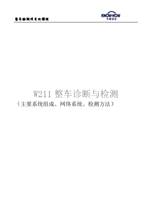
奔驰CAN-Bus总线介绍
CAN-Bus system
X30/20 (中央 中央CAN) 中央 CAN H = 黄色/白色 CAN L = 黄色 X30/21 (驱动系 CAN) 驱动系 CAN H = 蓝色/白色 CAN L = 蓝色 X30/28 (车辆动态 车辆动态CAN) 车辆动态 CAN H = 紫色/白色 CAN L =紫色 X30/30 and X30/31 (底盘 CAN) 底盘 CAN H = 绿色/白色 CAN L = 绿色 X30/32 ,X30/33 and X30/34 (内部 内部CAN) 内部 CAN H = 褐色/red CAN L = 褐色 X30/35 (Telematics CAN) CAN H = 黑色/白色 CAN L = 黑色 车前端CAN和诊断CAN分配器
附加数据总线系统的传输比率: 附加数据总线系统的传输比率 Vehicle dynamics CAN Drive train CAN Telematic CAN MOST LIN Bus 500 kbit/s 500 kbit/s 125 kbit/s 22Mbit/s 9.6 kbit/s (Max.20 kbit/s)
何正茂&汽车维修技术系列讲座
CAN-Bus system
X30/20 (中央 中央CAN) 中央 X30/20 无内部电阻 Central CAN内部电阻在CGW中(60 欧姆) X30/21 (驱动系 CAN) 驱动系 X30/21 有内部电阻( 60 欧姆) X30/28 (车辆动态 车辆动态CAN) 车辆动态 X30/28 无内部电阻 B24/25 (sensor cluster 120欧姆, ABR control unit 120欧姆) X30/30 and X30/31 (底盘 CAN) 底盘 X30/30 有内部电阻( 60 欧姆) X30/31 无内部电阻 X30/32 ,X30/33 and X30/34 (内部 内部CAN) 内部 无内部电阻 X30/32 (left) X30/33 (right) 有内部电阻( 60 欧姆) X30/34 无内部电阻 X30/35 (Telematics CAN) X30/35 无内部电阻
大众CANBUS

新型诊断线能够适用于旧型诊断接口。
针脚号 1 4 5 6 7
14 15 16
对应的线束 15号线 接地 接地 CANBUS(高) k线 CANBUS(低) L线 30号线
注:未标明的针脚号暂未使用。
功能
1. Canbus上的信息
由于不同区域Canbus总线的速率和识别代号不同,因此一个信号要从一个总 线进入到另一个总线区域,必须把它的识别信号和速率进行改变,能够让另 一个系统接受,这个任务由网关(Gateway)来完成。另外,网关还具有改变信 息优先级的功能。如车辆发生相撞事故,气囊控制单元会发出负加速度传感 器的信号,这个信号的优先级在驱动系统是非常高,但转到舒适系统后,网 关调低了它的优先级,因为它在舒适系统功能只是打开门和灯。
大众汽车基本培训
基本技术
CAN 数据总线(CAN-BUS)
售后服务培训中心
12.2002
基本内容: 简介
基本构造 数据传输 功能 驱动系统 舒适系统 传送安全性和故障处理
简介
Canbus的由来
由于现代汽车的技术水平大幅提高,要求能对更多的汽车运行参数进行控制,因而汽车 控制器的数量在不断的上升,从开始的几个发展到几十个以至于上百个控制单元。控制 单元数量的增加,使得它们互相之间的信息交换也越来越密集。为此德国BOSCH公司开 发了一种设计先进的解决方案-CAN数据总线,提供一种特殊的局域网来为汽车的控制 器之间进行数据交换。
域网。其速率分别为(Kbi0;
舒适系统(由30号线激活):100
信息系统(由30号线激活):100;
诊断系统(由30号线激活): 500
仪表系统(由15号线激活): 100;
基于canbus的汽车故障诊断系统

基于CANBUS的汽车故障诊断系统图2.1位的数值表示Fig.2.1Numericalexpressionofbit(12)应答所有接收器均对接收报文的相容性进行检查,应答一个相容报文,并标注一个不相容报文。
2.3CAN的分层结构CAN遵从OSI模型,按照OSI标准模型,CAN结构划分为两层:数据链路层和物理层。
而数据链路层又包括逻辑链路控制之层LLC和媒体访问控制子层MAC,而在CAN技术规范2.0A的版本中,数据链路层的LLC和MAC子层的服务和功能被描述为“目标层”和“传送层”。
CAN的分层结构和功能如图2.2所示。
图2.2CAN的分层结构和功能Fig.2.2Hierarchicalstructure&functionofCAN第3章总体方案设计图3.1总体设计图Fig.3.1Theblue-printinthemass用户通过掌上设备的界面选择车型、电控单元和相应的操作,通过诊断口和适配器工作,适配器主要是协调主机进行通信协议和电平的转换,同时选择通信端口。
3.2.1掌上设备的方案实现图3.2是掌上设备的总体框图【121。
掌上设备的核心是采用Samsung公司推出的16/32位RISC处理器¥3C2410A,为手持设备和一般类型应用提供了低价格、低功耗、高性能小型微控制器的解决方案。
它提供了非常丰富的内部设备[allloj:LCD控制器,支持NANDFlash系统引导,系统管理器(片选逻辑和SDRAM控制器),触摸屏接口,IIC.USB接口,USB主机,SD卡接口,2通道的SPI以及内部PLL时钟倍频器等等。
在外部扩展一片FLASH和两片SDRAM,FLASH启动和引导系统,在SDRAM上执行主程序代码。
微处理器内部带有LCD控制器,但是不能与触摸屏直接相连,需要一个驱动电路,通过触摸屏实现人机交互。
SD存储卡用来存储汽车电控单元的原始数据。
由于主机的通用性,所以在选择不同车型时,分别下载不同的单片机程序,因此单片机程序不能烧写到内部的FLASH中,而是要在外部扩展的程序空间里执行,这样可以每次根据车型不同下载不同的程序。
CAN-BUS 盾版 2.0 产品说明书
CAN-BUS Shield V2.0IntroductionCAN‐BUS is a common industrial bus because of its long travel distance, medium communication speed and high reliability. It is commonly found on modern machine tools, such as an automotive diagnostic bus.This CAN‐BUS Shield adopts MCP2515 CAN Bus controller with SPI interface and MCP2551 CAN transceiver to give your Arduino/Seeeduino CAN‐BUS capability. With an OBD‐II converter cable added on and the OBD‐II library imported, you are ready to build an onboard diagnostic device or data logger.Previously we have made two versions of CAN‐BUS Shield, the V1.0 and V1.2. They are all awesome shields that widely liked by our users. In order to make it better, several months ago we conducted a survey about CAN‐BUS Shield V1.2 and received many valuable advices (Thanks to all the users who replied to us), so we decided to make an update and here it is ‐ CAN‐BUS Shield V2.VersionThis document applies to the following version of products:Version Released DateCAN BUS Shield V1.0 Oct 14, 2012CAN BUS Shield V1.1 Aug 10, 2013CAN BUS Shield V1.2 Jan 05, 2015CAN BUS Shield V2.0 Aug 01,2017Version TrackerFeatures V1.2 V2.0 CAN‐BUS Controller MCP2515 MCP2515CAN Transceiver MCP2551 MCP2551Default OBD Pinout OBD‐II Standard OBD‐II Standard CAN Standard Pinout Not compatible Compatible (jumper) INT Pin Not changeable D2 or D3 (jumper) CS pin for TF card slot No TF card slot D4 or D5 (jumper)Features V1.2 V2.0 Serial Grove D0/D1 A0/A1I2C Grove A4/A5 SDA/SCLGrove Orientation Vertical HorizontalP1 pad Front of the shied Back of the shieldWhat’s new in CAN BUS Shield V2.0Hardware∙OBD‐II or CAN standard pinout can be selected by switching jumpers on DB9 interface, the default pinout is OBD‐II.∙Add a TF card slot for data storage and the CS pin can be either set to D4 or D5.∙The INT pin can be set to D2 or D3 by switching jumpers on the back of the shield.∙Moved the P1 pad from front to the back of the shield to make it easier to cut and solder.∙Consider that the D0/D1 pin are usually used for downloading code, we changed the serial Grove connector to pin A0/A1.∙The I2C grove connector is also changed to more reasonable standard SDA/SCL pin instead of previous A4/A5. ∙The two grove connectors are both changed to horizontal rather than vertical to the shield so that it would be more convenient when connecting to other grove modules.Software∙Add the function and example to access the data of your car.∙Add the function to read the SD card.∙Add the example to store the data of your car into the SD card.∙Fix some bugs and optimize some program.D‐Sub CANbus PinOutpin# Signal names Signal Description1 Reserved Upgrade Path2 CAN_L Dominant Low3 CAN_GND Ground4 Reserved Upgrade Path5 CAN_SHLD Shiled, Optional6 GND Ground,Optional7 CAN_H Dominant High8 Reserved Upgrade Path9 CAN_V+ Power, OptionalWhat if I want to connect this shield to my carIf you want to read data or control your car, there’s an OBD>DB9 cable available for you, this cable make easier to connect to OBD‐connector and DB9‐connector. This cable will also work with anything that has a OBD‐connector. Add a power switch makes such a satisfying click.USB‐CAN AnalyzerIf you want a CAN Bus Analyzer to debug your CAN Bus, this USB‐CAN Analyzer isrecommended.Features∙Implements CAN V2.0B at up to 1 Mb/s∙Industrial standard 9 pin sub‐D connector∙OBD‐II and CAN standard pinout selectable.∙Changeable chip select pin∙Changeable CS pin for TF card slot∙Changeable INT pin∙Screw terminal that easily to connect CAN_H and CAN_L∙Arduino Uno pin headers∙2 Grove connectors (I2C and UART)∙SPI Interface up to 10 MHz∙Standard (11 bit) and extended (29 bit) data and remote frames∙Two receive buffers with prioritized message storageCAN BUS Shield Work well with Arduino UNO (ATmega328), Arduino Mega (ATmega1280/2560) as well as Arduino Leonardo (ATmega32U4).Hardware Overview1.DB9 Interface ‐ to connect to OBDII Interface via a DBG‐OBD Cable.2.V_OBD ‐ It gets power from OBDII Interface (from DB9)3.Led Indicator:o PWR: powero TX: blink when the data is sendingo RX: blink when there’s data receivingo INT: data interrupt4.Terminal ‐ CAN_H and CAN_L5.Arduino UNO pin out6.Serial Grove connector7.I2C Grove connector8.ICSP pins9.IC ‐ MCP2551, a high‐speed CAN transceiver (datasheet)10.IC ‐ MCP2515, stand‐alone CAN controller with SPI interface (datasheet)11.SD card slotWhen you use more than two CAN Bus Shield in one net, you should take the impedance into consideration. You should either cut P1 in the PCB with a knife, or just remove R3 on the PCB.Pin mapThe FREE pin is available for the other usages.DB9&OBDii InterfaceCS_CAN pinSPI_CS pin of V2.0 is connected to D9 by default. If you want to change to D10, please follow below instructions.∙Step1: Take a look at the backside of the PCBA, you will find a pad named CS_CAN.∙Step2: Cut the wire between pad9 and the middle pad.∙Step3:Weld the middle pad and pad 10.Be careful with the box cutter, it’s easy to hurt yourself or the PCBA.INT pinINT pin of V2.0 is connected to D2 by default. If you want to change to D3, please follow below instructions.∙Step1: Take a look at the backside of the PCBA, you will find a pad named INT.∙Step2: Cut the wire between pad 2 and the middle pad.∙Step3:Weld the middle pad and pad 3.SPI pinsThe SPI pins (SCK, MISO, MOSI) are routed to the ICSP pins by default. But for some boards, the SPI pins are located at D11~D13. if this happens, you need make some change to the PCBA.Take a look at the backside of the PCBA, there’re three pads, MOSI, MISO and SCK, they are connected to A by default. You can change them to B if needed.For Arduino UNO, Arduino Mega, Arduino Leonardo and any others AVR based Arduino boards, it works well by default setting.Be careful when you are going to change SPI pins, it’s easy to hurt yourself or the PCBA. Getting StartedHere’s a simple example to show you how CAN‐BUS Shield works. In this example we need 2 pieces of CAN‐BUS Shields as well as Arduino or Seeeduino.This example is built under Arduino IDE version 1.6.9.STEP1: What do we needName Function QtyCAN‐BUS Shield CAN Bus communication 2Seeeduino V4.2 Controller 2Jumper Wire connection 2STEP2: Hardware ConnectionInsert each CAN‐BUS Shield into Seeeduino V4.2, and connect the 2 CAN‐BUS Shield together via 2 jumper wires. Shown as below images.CAN_H to CAN_H, CAN_L to CAN_LSTEP3: SoftwarePlease follow how to install an arduino library procedures to install CAN BUS shield library.Click on below button to download the library./How_to_install_Arduino_Library/https:///Seeed‐Studio/CAN_BUS_ShieldInstall the library to your Arduino IDE when it is downloaded.One of the node (a node means Seeeduino + CAN_BUS Shield) acts as master, the other acts as slaver. The master will send data to slaver constantly.Each node can act as master before the code being uploaded.Open the send example (File > Examples > CAN_BUS_Shield‐master > send) and upload to the master.Open the receive_check example (File > Examples > CAN_BUS_Shield‐master > receive_check) and upload to the slaver.STEP4: View ResultOpen the Serial Monitor of Arduino IDE(slaver), you will get the data sent from the master.APIs1. Set the Baud rateThis function is used to initialize the baud rate of the CAN Bus system.The available baud rates are listed as follows:#def ine CAN_5KBPS 1#def ine CAN_10KBPS 2#def ine CAN_20KBPS 3#def ine CAN_25KBPS 4#def ine CAN_31K25BPS 5#def ine CAN_33KBPS 6#def ine CAN_40KBPS 7#def ine CAN_50KBPS 8#def ine CAN_80KBPS 9#def ine CAN_83K3BPS 10#def ine CAN_95KBPS 11#def ine CAN_100KBPS 12#def ine CAN_125KBPS 13#def ine CAN_200KBPS 14#def ine CAN_250KBPS 15#def ine CAN_500KBPS 16#def ine CAN_666kbps 17#def ine CAN_1000KBPS 182. Set Receive Mask and FilterThere are 2 receive mask registers and 5 filter registers on the controller chip that guarantee you getting data from the target device. They are useful especially in a large network consisting of numerous nodes.We provide two functions for you to utilize these mask and filter registers. They are:Mask:init_Mask(unsigned char num, unsigned char ext, unsigned char ulData);Filter:init_Filt(unsigned char num, unsigned char ext, unsigned char ulData);∙num represents which register to use. You can fill 0 or 1 for mask and 0 to 5 for filter.∙ext represents the status of the frame. 0 means it’s a mask or filter for a standard frame. 1 means it’s for a extended frame.∙ulData represents the content of the mask of filter.3. Check ReceiveThe MCP2515 can operate in either a polled mode, where the software checks for a received frame, or using additional pins to signal that a frame has been received or transmit completed.Use the following function to poll for received frames.INT8U MCP_CAN::checkReceive(void);The function will return 1 if a frame arrives, and 0 if nothing arrives.4. Get CAN IDWhen some data arrive, you can use the following function to get the CAN ID of the “send”node.INT32U MCP_CAN::getCanId(void)5. Send DataCAN.sendMsgBuf(INT8U id, INT8U ext, INT8U len, data_buf);It is a function to send data onto the bus. In which:∙id represents where the data comes from.∙ext represents the status of the frame. ‘0’ means standard frame. ‘1’ means extended frame.∙len represents the length of this frame.∙data_buf is the content of this message.For example, In the ‘send’ example, we have:unsigned char stmp[8] = {0, 1, 2, 3, 4, 5, 6, 7};CAN.sendMsgBuf(0x00, 0, 8, stmp); //send out the message 'stmp' to the bus and tell other devices this isa standard frame from 0x00.6. Receive DataThe following function is used to receive data on the ‘receive’ node:CAN.readMsgBuf(unsigned char len, unsigned char buf);In conditions that masks and filters have been set. This function can only get frames that meet the requirements of masks and filters.∙len represents the data length.∙buf is where you store the data.Generate a New BaudRateWe had provided many frequently‐used baud rates, as below:#def ine CAN_5KBPS 1#def ine CAN_10KBPS 2#def ine CAN_20KBPS 3#def ine CAN_25KBPS 4#def ine CAN_31KBPS 5#def ine CAN_33KBPS 6#def ine CAN_40KBPS 7#def ine CAN_50KBPS 8#def ine CAN_80KBPS 9#def ine CAN_83KBPS 10#def ine CAN_95KBPS 11#def ine CAN_100KBPS 12#def ine CAN_125KBPS 13#def ine CAN_200KBPS 14#def ine CAN_250KBPS 15#def ine CAN_500KBPS 16#def ine CAN_666KBPS 17#def ine CAN_1000KBPS 18Yet you may still can’t find the rate you want. Here we provide a software to help you tocalculate the baud rate you need.Click here to download the software, it’s in Chinese, but never mind, it’s easy touse.https:///SeeedDocument/CAN_BUS_Shield/raw/master/resource/CAN_Baudrate_CalcV1.3.zipThis software supports Windows system only. If you can’t open it, please feel free to contact *************** for support.Open the software, what you need to do is to set the baud rate you want, and then do some simple setting, then click calculate.Then you will get some data, cfg1, cfg2 and cfg3.You need to add some code to the library.Open mcp_can_dfs.h, you need to add below code at about line 272:#def ine MCP_16MHz_xxxkBPS_CFG1 (cfg1) // xxx is the baud rate you need#def ine MCP_16MHz_xxxkBPS_CFG2 (cfg2)#def ine MCP_16MHz_xxxkBPS_CFG3 (cfg2)Then let’s go to about line 390, add below code:#def ine CAN_xxxKBPS NUM // xxx is the baudrate you need, and NUM is a number, you need to get a different from the other rates.Open mcp_can.cpp, goto the function mcp2515_configRate(at about line 190), then add below code:case (CAN_xxxKBPS):cf g1 = MCP_16MHz_xxxkBPS_CF G1;cf g2 = MCP_16MHz_xxxkBPS_CF G2;cf g3 = MCP_16MHz_xxxkBPS_CF G3;break;Then you can use the baud rate you need. And please give me a pull request at github when you use a new rate, so I can add it to the library to help other guys.ProjectsIf you want to make some awesome projects with CAN‐BUS shield, here are some projects for reference.Volkswagen CAN BUS GamingEver wanted to play a car/truck simulator with a real dashboard on your PC? Me too! I’m tryingto control a VW Polo 6R dashboard via CAN Bus with an Arduino Uno and a Seeed CAN BusShield. Inspired by Silas Parker. Thanks Sepp and Is0‐Mick for their great support!Hack your vehicle CAN‐BUSModern Vehicles all come equipped with a CAN‐BUS Controller Area Network, Instead of havinga million wires running back and forth from various devices in your car to the battery, itsmaking use of a more clever system.All electronic functions are connected to the TIPM, (Totally integrated Power Module), such assolenoids/relays to lock the doors or mini motors to wind the windows etc.From each node (IE Switch pod that controls your windows or electric door locks) it broadcastsa message across the CAN. When the TIPM detects a valid message it will react accordingly like,lock the doors, switch on lights and so on.FAQQ1: I can’t get data from other CAN device.∙Check if the connection is right∙Check if the baud rate setting is rightQ2: The serial monitor print Init Fail.∙Check if the CS pin setting is matched with the code. For CAN Bus Shield V1.1/1.2, CS pin is connected to D9, others are to D10.Q3. Where can I find technical support if I have some other issues.∙You can post a question to Seeed Forum or send an email to ********************.Help us make it betterWelcome to the new documentation system of Seeed Studio. We have made a lot of progress comparing to the old wiki system and will continue to improve it to make it more user friendly and helpful. The improvement can't be done without your kindly feedback. If you have any suggestions or findings, you are most welcome to submit the amended version as ourcontributor via Github or give us suggestions in the survey below, it would be more appreciated if you could leave your email so that we can reply to you. Happy Hacking!/CAN‐BUS_Shield_V2.0/ 9‐7‐17。
吉利 CAN-bus系统
LIN线上的信号
各从节点反馈的信号
主节点发送的信号
玻璃开着 玻璃关着 玻璃运行中 车型代码 车速 玻璃全关命令 KL_15
五、 EC-1/2项目的LIN通讯故障
测试接口: CAN:OBD口的6脚(CAN_H)和14脚(CAN_L) LIN:玻璃升降器4脚及地线。
E260 E250 E253 E257 E255
设置DTC的ECU
ACU ACU BCM BCM BCM EMS EMS ICU ICU ICU ICU
DTC(故障代码))
U1100 U1130 U1200 U1210 U1230 U1300 U1320 U1400 U1410 U1420 U1430
描述
和ABS丢失通讯 和EMS丢失通讯 和ABS丢失通讯 和EMS丢失通讯 和ACU丢失通讯 和ABS丢失通讯 和BCM丢失通讯 和ABS丢失通讯 和ACU丢失通讯 和BCM丢失通讯 和EMS丢失通讯
ICU
U1601
EMS
U1602
ACU
U1603
BCM监测到BUS-OFF ICU监测到BUS-OFF EMS监测到BUS-OFF EMS监测到BUS-OFF
四、四门防夹玻璃升降器模块
此模块主要集成在玻璃升降器总成中,BCM通过LIN线来实现对玻璃升降器的控 制。目前EC-1/2的LIN总线主要实现的是遥控升窗功能和诊断数据读取。
防抱死系统 ABS
安全气囊单元 ACU
高速CAN总线
发动机控制器 EMS
组合仪表 ICU
诊断口
总线波特率:
HS_CAN:500Kbps LIN:19.2Kbps K线:10.4Kbps
胎压监测系统 TPMS
K线
汽车CAN总线详细教程
2003年,大众集团在新PQ35平台上使用五重结构的Canbus系统,并且出现了单线的LIN-BUS。
CAN技术的发展
20世纪80年代,Bosch的工程人员开始研究用于汽车的串行总线系统,因为当时还没有一个网络协议能完全满足汽车工程的要求。参加研究的还有Mercedes-Benz公司、Intel公司,还有德国两所大学的教授。 1986年, Bosch在SAE(汽车工程人员协会)大会上提出了CAN 1987年,INTEL就推出了第一片CAN控制芯片—82526;随后Philips半导体推出了82C200。 1993年,CAN的国际标准ISO11898公布 从此CAN 协议被广泛的用于各类自动化控制领域。
但是轿车上基于CAN的控制网络至今仍是各大公司自成系统,没有一个统一标准。
基于CAN的应用层协议应用较通用的有两种:DeviceNet(适合于工厂底层自动化) 和 CANopen(适合于机械控制的嵌入式应用)。 任何组织或个人都可以从DeviceNet供货商协会(ODVA)获得DeviceNet规范。购买者将得到无限制的、真正免费的开发DeviceNet产品的授权。 DeviceNet自2002年被确立为中国国家标准以来,已在冶金、电力、水处理、乳品饮料、烟草、水泥、石化、矿山等各个行业得到成功应用,其低成本和高可靠性已经得到广泛认同。
总线技术及应用
PART 1
CAN 数据总线(CAN BUS)
点击此处添加副标题
演讲人姓名
202X
CAN通信技术概述
CAN ( Controller Area Network ) 即控制器局域网络。由于其高性能、高可靠性、及独特的设计,CAN越来越受到人们的重视。国外已有许多大公司的产品采用了这一技术。
现代汽车canbus多路信息传输系统
统 控制单元 和控制单元插角最少化应 的 用,从而节省更多有用空间
优 CAN数据总线符合国际标准,便于 点 不同的控制单元进行数据交换
控制单元1 控制单元2
检测时,关闭点火开关,断开两 个控制单元。
检查数据总线是否断路、短路或 对正极/地短路。
如果数据总线无故障,更换较易 拆下〔或较廉价〕的一个控制单 元试一下。
如果数据总线系统仍不能正常工 作,更换另一个控制单元。
三个或更多控制单元组成的双线式 数据总线系统的检测
控制单元1 控制单元2 控制单元3
仪表内的诊断接口 J285
Gateway 的作用是使所有连接在CAN总线上的控制单元 实现数据交换 驱动总线 舒适总线和 显示总线 (信息娱乐总线). 因为这几种总线的传输速度是不同的,所以不能直接进 行数据交换。
空调控制单元 E87
Data telegram
Gateway
作用
作为诊断 gateway...
Motronic 控制单元
自动变速器 控制单元
ABS/EDL 控制单元
在特殊情况下,CAN数据总线的连接 节点可能会在发动机控制单元里
线束的节点汇集 在发动机控制单 元中
Gateway
CAN 数据总线网络
仪表内的 Gateway
自动变速箱控制单元 J217
舒适系统中央控制单元 J393
Control unit for 4LV J537
舒适系统CAN数据总线传递数据的功能
中央门锁控制功能 电动窗控制功能 照明开关控制功能 电动调节和加热后视镜控制 功能 故障自诊断功能