西门子SITRANS FM MAG 8000电磁水表
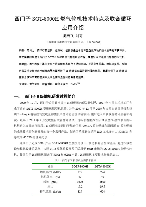
西门子SGT5—8000H型燃机介绍
言 ,是 有所 差 异 的 。但 这种 严 格 术 语 上 的 差 异并
不是 实质 性 的 。对 不 同频率 领域 的健 康风 险研究 只 能针对 特定 频率 进行 研究 ,并按 照其 生物 效应 、
人体 作用 机制 相 似来分 频段 进行 评估 。
表 8—2 美 国 NIEHS评 估 报 告 中 的 相 关 术 语 及 频 段 划 分
上 海 电力
2010年第 2期
西 门 子 SGT5—8000H 型燃 机介 绍
陈 霞 ,曹锋 杰
(1.华 能 上 海 燃 机 发 电有 限责 任 公 司 ,上 海 200942; 2.江苏 南 通 市 民 防 (Jk防 )指 挥 信 息 保 障 中心 ,江 苏 南 通 226001)
SGT5—8000H 型燃 机设 计 的发 动机是 在 电网 频 率 为 5O Hz或 60 Hz发 动 机 的经 验 基 础 上 建 造 的 。在这 款新 颖 发 动 机 中 ,应 用 了多 项 新 的设 计
理 念 以及“Six Sigma”设 计 工具 。其 中 ,选 择 空冷 设 计 理 念 可 以 使 用 户 在 市 场 解 除 管 制 的 环 境 中得 到 更 大 的 运 行 灵 活 性 。
No.322)》和《极 低 频 场 环 境 健康 准 则 (EHC No.
238》中 ,明确指 出 了上 述 官 方文 献 中“极 低 频 ”的 范 围 是 0 HZ~ 100 kHz。EHC No.238指 出 :在 该 频 率 范 围 内 已 进 行 的绝 大 部 分 研 究 都 是 针 对 工 频 (50或 60 Hz)磁场 的 ,其 中也研究 了工频 电场 。 另外 ,还有 很 多研 究 文 献 是 关 于甚 低 频 (VLF,3 — 30 kHz)场 、用 于 磁 共 振 成 像 的 投 切 陡 波 磁 场 以及 由视 频显 示单元 产生 的弱甚低 频场 。
西门子AG Mag 5000 6000及相关传感器安装和故障排查指南说明书
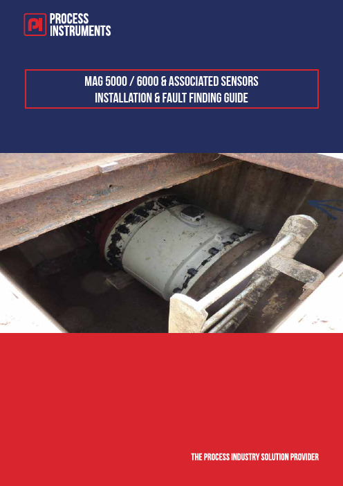
Index …A.0 Recommended Tools Page 51.0 Mechanical Installation Page 6 1.1 Sensor Installation Page 61.2 Sensor Prom Installation. Page 72.0 Wire Connections Page 8 2.1 Wire Connections for Compact Sensor. Page 8 2.2 Wire Connections for Remote Sensor. Page 8 2.3 Cable Specifications Page 9 2.4 Examples of Good and Bad Installations. Page 102.5 Overview of Transmitter Connections Page 113.0 Parameters Page 12 3.1 Basic Settings Page 14 3.2 Output Parameters Page 15 3.3 Service Menu Page 163.4 Sensor Characteristics Page 184.0 Fault Finding. Page 19 4.1 Error Codes. Page 19 4.2 Sensor Fault Finding. (Sensor Full) Page 21 4.3 Sensor Fault Finding. (Sensor Empty) Page 224.4 Coil Resistance Table (Connections 85 & 86) Page 235.0 Sitrans FM Magflo Verificator – Important Instructions Page 245.1 Verificator – Check List Page 266.0 Appendix. Page 27 6.1 Flow Meter Check List, Compact. Page 27 6.2 Flow Meter Check List, Remote. Page 27 6.3 Sensor Operating Range Page 286.3 Cable Kit Part Numbers Page 297.0 Technical Support Page 30A.0 Recommend ed ToolsInsulation Tester 500V.ExampleRS Pro, Insulation Tester 4000M CAT III 1000 VRS Stock No. 893-7913Moving Coil MeterExampleMaplin MT 2017 Large Analogue MultimeterCode: N60LK1.0 Mechanical Installation 1.1 Sensor InstallationSensor needs to be full at all times.Avoid positioning measuring electrodes at top and bottom of pipe.Straight Diameters for optimum performanceVertical Pipes1.2 Sensor Prom Installation.1 2 3 41Sensor shipped with Sensor-Prom installed in junction Box.2Remove SensorProm before potting terminal box’3Make sure Sensor-Prom details match details of Magflow Sensor, Cal Factor & Serial Number4Install Sensor-Prom into transmitter REMOTE junction box (as shown).2.0 Wire Connections2.1 Wire Connections for Compact Sensor.2.2 Wire Connections for Remote Sensor.2.3 Cabl e SpecificationsColourCod e for Factory Cable Kit.2.4 Exampl es of Good and Bad Installations.Verificator insulation test failed Verificator insulation test Passed2.5 Overview of Transmitter ConnectionsElectrode connections – 82, 0, 83 standard configuration with No empty pipe detection (EPD). Terminals 81 and 84 used for empty pipe detection, and can only be used with Siemens supplied double screen cable. Screen cable at sensor end only. Keep unscreened lengths to a maximum of 50mm. Coil connections - 85 – 86 standard screened cable can be used. Connect screen to earth and sensor and transmitter. to prevent corruption of electrode3.0 ParametersThe factory setting of 1000 can be re-established asfollows:Switch off power supplyPress the TOP UP (Top Left) key and switchon the power supplyRelease the key after ROM and RAM testsare completedThe user code is now reset to 1000.3.2 Output ParametersCurrent OutputNOTE:Current Output - “Time Constant” effects response time of unit, (Mag 6000/5000) not just themA output.Time Constant can only be altered if mA is set to ON.If the output terminals (31, 32) are not connected , Turn off mA output after adjusting “Time Constant”, this will prevent P42 alarm. May require power re-cycle to clear alarm. Digital Output Set to Pulsed3.3 Service MenuExcitation frequency can be used to check for noise,1. Lower Low flow cu-off to 0.1%2. Turn Off Excitation.3. Any flow value indicated on the top line would indicateexcessive noise.4. Do not use the Verificator, and check electrode and coilcables.Signal suitability is a level from 0 to 9 of the electrode measured voltage.Level 0 is equal to the limit value that is set for empty pipe error detection, and level 9 is the best signal measured.3.3 Service Menu Continued3.4 Sensor Characteristics4.0 Fault Finding.4.1 Error Cod es.The converter system is equipped with an error and status log system with 3 groups of information.1. Information without a functional error involved2. Warnings which may cause malfunction in the application. The cause of the error maydisappear on its own.3. Permanent errors which may cause malfunction in the application. The error requires anoperator intervention.4. Fatal error which is essential for the operation of the flowmeter2 menus are available in service and operator menus for registration of information and errors1. Error pending2. Status logTwo Flashing Triangles indicate a Fault Condition The current Error can be viewed in run ModePress Until Error Pending is DisplayedError Logs Can be view under Service Mode4.1 Error Codes Continued..W = Warning P = Permanent F = Fatal4.2 Sensor Fault Finding. (Sensor Full)4.3 Sensor Fault Finding. (Sensor Empty)4.4 Coil Resistance Table (Connections 85 & 86)1) On MAG 1100 DN 15 produced as from May 1999 the coil resistance must be 86 ohm, +8/ 4 ohm. All resistance values are at 20 °C.The resistance changes proportionally 0.4% / °C.5.0 Sitrans FM Magflo Verificator Important InstructionsBEFORE VERIFICATIONSteps 1 to 5 below MUST be completed before verification is carried out 1. Make sure the Sitrans FM sensor is full of liquid and the flow meter isoperating.2. Switch off the power to the flow meter to be verified.3. Remove the transmitter (Mag5000 or Mag6000).4. Ensure sensor and transmitter are correctly earthed.5. Insulation Check – Coils.Using an insulation tester (megger), with 500v insulation voltage, check for correct insulation between the electromagnetic coils and ground.Measure the resistance between terminal 85 and ground, then betweenterminal 86 and ground.The resistance should be infinite (greater than 500 Megohms).If the insulation test fails, DO NOT connect the Verificator to the flow meter.Warning: Connecting to a flow meter which has failed insulation will damage the Verificator.Typical repair cost: £2000.00 to £3000.00.CONNECTING THE VERIFICATORSteps 6 to 9 MUST be done with power disconnected from both Verificator and flow meter.6. Place the Verificator close to the transmitter.7. Plug the 3 colour coded flying leads into the adaptor.(Line up the plug and socket red dots and push firmly into place).8. Place the adaptor onto the terminal box and secure the screws.9. Plug the transmitter into the Verificator.DURING VERIFICATION10. Switch on the power to the Sitrans FM flow meter.11. Turn on the Verificator power switch.12. Wait for Verificator to display the “File #” list.13. Choose the file name for the flow meter to be verified.14. Press the “Go” key to start the test.Refer to the Verificator manual for detailed information about the verification process and diagnostic messages.Turn over for further instructions…Important:Do not press the keypad or change any settings on the transmitter during the verification process.Never switch off power to the Verificator during a test, unless the test has been stopped (by pressing the “Esc” key).AFTER VERIFICATION15. When the verification is finished press “Go” to return to the main menu andautomatically store the data.16. Turn off the Verificator power switch.17. Switch off the power to the Sitrans FM flow meter.18. Remove the adaptor and re-fit the transmitter.19. Switch on the power to the Sitrans FM flow meter.WarningDisconnection of the transmitter or the Verificator adaptor during a test may damage the Sensorprom module, the transmitter or the Verificator.In normal use the Verificator power cable (maximum 2.5m) should be used in a workshop environment when downloading data to a PC following site verifications.5.1 Verificator – Check ListCoil circuit (connections 85 & 86) must be Megger tested with reference to earth before using Verificator. Failure to comply too this procedure can result in damage to Verifcator. If in doubt please contact Siemens.There are a number of possible reasons why the Verificator may fail the Insulation test on a Magflo flowmeter. The most common reasons are listed below.1.0 Converter Failed1. Press ESC to end Verification2. Replace MAG5000/MAG60002.0 Insulation Test Failed2.1 Compact Mounted Converter1 Black moulded coil and electrode connectors not mounted on the connection card.2 The pipe is not full of fluid.3 Moisture in the connection box.4 Electrodes or coil circuit grounded. (Carry out sensor checks)2.2 Remote mounted converter1 The pipe is not full of fluid.2 Meter body not grounded to the fluid. (Confirm if Magflo type has earthing electrodes or an earthingring fitted).3 Incorrect wiring connections of the coil and electrodes4 Unscreened lengths of wire on the electrode circuit. Max unscreened 50mm (better with 25mmmax) at any point including Junction Boxes and cabling inside panels.5 Discontinuous screen in any Junction Boxes or panel terminations.6 Incorrect cable being used i.e multi core (spare cores act as signal pick up aerials) or unscreenedcables.7 Two separate cables not used for coil and electrodes.8 Screen on the coil cable not connected at both ends9 Crimps used on wiring and poor connection made.10 Moisture in either the sensor or remote electronic connection boxes.11 Electrodes or coil circuit grounded. (Carry out sensor checks)12 Lightning arresters in circuit. (These have a built in grounding circuit)13 Crossed connection between two sensors i.e electrode connections made to a different converter tothe one driving the coils.If possible try a signal converter compact mounted in order to eliminate cable problems. From our experience incorrect cable installation is the main cause of Insulation failure when using the Verificator.3.0 Sensor Failed – Magnetism FaultData relating to magnetic properties deviates from data stored in Sensor-promTrouble shooting may reveal: -1. Short circuit within excitation coils or to ground, This may have damaged Verificator.2. Bad or missing connection of coil cable.3. Corrosion or loose connection within the magnetic circuit.4. Foreign magnetic material within the flow sensor5. Sensor-prom failed or corrupted (Indicated by error F61 on signal converter display)6. Changing excitation frequency from default can cause a coil error change back to default whileperforming Verification.6.0 Appendix.6.1 Flow Meter Check List, Compact.Check power connection for the Mag 6000, including earth connectionCheck Earth connection to bottom plateEnsure Sensor Prom is installed and serial number matches serial number on junction boxEnsure Molded plug (2 pins) with indication 85 & 86 is connected to PCB with corresponding number.Ensure Molded plug (3 pins) with indication 82, 83 & 0 is connected to PCB with corresponding number.Insert Communication card into base of Mag 6000 transmitter if required.Test coil insulation at 500 Volts, measure 85, to earth, and 86 to earth.With Moving coil meter test electrode circuit (see page xx)Fit Mag 6000 transmitter and tighten 2 fixing screws.Turn on power and check for and errors.6.2 Flow Meter Check List, Remote.Check power connection the Mag 6000, including earth connectionRemove Sensor Prom from sensor junction boxEnsure Sensor Prom is installed in remote transmitter and serial number matches serial number on junction box of connected sensorFit white terminal block to metal plate in sensor using x2 fixing screws.Fix Molded Plug into white terminal block in sensor ensuring all screw as tight Using recommended cable make wire connections in accordance with page xx. Ensure unscreened lengths in sensor and transmitter are less than 50mm.Insert Communication card into base of Mag 6000 transmitter if required.Test coil insulation at 500 Volts, measure 85, to earth, and 86 to earth.With Moving coil meter test electrode circuit (see page xx)Fit Mag 6000 transmitter and tighten 2 fixing screws.Turn on power and check for and errors.6.3 Sensor Operating RangeIdeal flow velocities between 0.5 and 5 m/sec meter will operate up to 10m/sec.6.4 Cable Kit Part NumbersCabling:Cable kit with standard coil cable, 3 x 1.5 mm2/18 gage with shield PVC and electrode cable double shielded, 3 x 0.25mm2 (-30 to +70 deg C)Steel Wired Armoured Cabling:Cable kit with standard coil cable, 3 x 1.5 mm2/18 gage with shield PVC and electrode cable double shielded, 3 x 0.25mm2 (-30 to +70 deg C).Important: Due to the weight of the cable, armoured cabling is not suitable for pre-potted sensors.。
西门子 7KG85xx 电能质量仪表和电力监测仪 设备手册说明书

电能质量仪表和 电力监测仪SICAM P850/P855 7KG85xxV02.22/V02.60设备手册前言开源软件目录用户信息1概述2设备设计3被测量与记录4入门5连接原理6使用PC时的操作7使用显示屏时的操作8时间同步9校准10维护、存储和运输11故障和LED指示灯12技术数据13运行指示14操作参数15词汇表索引E50417-H105D-C482-A7免责声明可能会有更改和错误,恕不另行通知。
本文所述内容仅包含产品的一般描述和/或性能特点,并不一定会反映所述产品的具体情况,可能会随着产品的进一步开发而进行修改。
性能特点要求仅在签署合同中明确约定后才具有约束力。
文档版本:E50417-H105D-C482-A7.04版本:2019年07月版所述产品版本:V02.22/V02.60版权版权所有 Siemens 2019。
保留所有权利。
未经书面授权禁止披露、复制、分发和编辑本文档或者使用和传播其中的内容。
保留所有权利,包括专利权、实用新型所有权或外观设计所有权。
注册商标SIPROTEC™、DIGSI™、SIGRA™、SIGUARD™、SAFIR™、SICAM™ 和 MindSphere™ 是西门子股份公司的商标。
任意禁止未经授权使用。
本文中的所有其他产品名称可能是商标,若第三方出于自身利益使用这些商标,可能会侵犯所有者的权益。
注意鉴于人身安全,请遵守本文所述的警告和安全说明(若有)。
3SICAM P850/P855,7KG85xx,设备手册E50417-H105D-C482-A7,2019年07月版前言本手册目的本手册介绍了电能质量仪表和电力监测仪SICAM P850/P855的应用、功能、安装、调试和操作。
目标受众本手册适用于电气系统和发电厂的项目工程师、调试人员及操作人员。
适用范围本手册适用于电能质量仪表和电力监测仪SICAM P850/P855。
符合性声明标准有关更多信息,敬请访问以下网站中的UL 数据库: 。
西门子SGT5-8000介绍
PCS 燃烧器采用的是分级燃烧的设计理念,分为 A、B、C、D 级以及先导扩散燃烧 级。其中,A 和 B 级为主燃烧级,各有 4 个带旋流的预混燃烧器组成,其分布如下图 3 所示。
BBAAAABB
图 3 A、B 级燃烧器分布示意图
C 级燃烧器位于导流衬套内,在主燃烧器和值班燃烧器空气气流上游。 D 级燃烧器是先导预混燃烧级,以调整燃烧动态特性为目的。
本节以 SGT5-8000H 为例,简述联合循环的配置。由于 ISO 工况下,H 级燃机的排气温 度高达 627℃,因此与之配套的余热锅炉为采用西门子 BensonTM 炉专利技术的三压再热锅炉, 其中高压为直流锅炉,中、低压为汽包炉,蒸汽参数为高压 17MPa/600℃,中压 3.5MPa/600
三、 机组运行灵活性
西门子 H 级燃机在设计时充分考虑了用户对快速启停、负荷快速变化、燃料灵活性 和环保等方面的要求,本节从负荷变化率、负荷变化范围、FACY™技术和燃料灵活性四 个方面进行介绍。
3.1. 启动时间和升负荷速率。以 50Hz 机组为例,正常的升负荷速率为 15MW/min, 燃机从并网到满负荷 375MW 仅需 25min。如电网急需负荷,可以选择快速升负荷模式, 其速率为 35MW/min,单循环仅须 10 分钟就能从并网升至 350MW。在联合循环启动工 况下,升负荷速率受汽轮机冷、热态工况影响而不同。热态工况下,升负荷速率大于 25MW/min,机组在 30 分钟以内就能将负荷升至 500MW 以上,具备快速响应电网负荷 需求的能力,见图 4。
机型
燃机出力 (MW) 燃机效率 (%)
转速 (rpm) 压比
排气流量 (kg/s))
SGT5-8000H 375 40 3000 19.2 829
SIEMENS sitrans LR250(HART) 快速启动手册
sitrans7ML19985QX81SITRANS LR250 (HART) – QUICK START MANUAL Page EN-1SITRANS LR250 (HART) Siemens Milltronics Process Instruments Inc.1954 Technology Drive, P .O. Box 4225Peterborough, Ontario, Canada, K9J 7B1Email:*************************快速启动手册技术支持西门子提供24小时技术支持请联系您当地的西门子仪表销售人员或拨打热线 400-810-4288请登陆www.ad.siemens.com.cn/pi查找各种资料MILLTRONICS是Siemens Milltronics Process Instruments Inc.公司的注册商标。
虽然我们对本手册的内容是否与仪表一致进行了核对,但仍可能存在变化。
这样一来我们不能确保完全的一致。
手册内容会进行有序的核查和纠正,堪误表登录在后续版本里。
我们欢迎使用者数据数据可能有变动。
提出各种改进建议。
这份文档可以以装订版本和电子版本形式获得。
我们鼓励用户购买西门子设计并授权审定的装订手册,或者查看电子版本。
西门子公司不为部份或整个的装订或电子版本的复制品负责。
本手册略述了SITRANS LR250(HART)的主要特点和功能。
完整的操作指南请查阅完整手册。
您可以从www.siemens.com/LR250网页下载.关于本手册内容的疑问您可以直接联系:Page EN-2SITRANS LR250 (HART) – QUICK START MANUAL 7ML19985QX81SITRANS LR2501.This symbol is used when there is no corresponding caution symbol on the product.••安全指导方针FCC一致性警告标示一定要注意,以保证人身安全和保护本仪表和整个装置。
电磁流量计选型手册

法兰外 径(mm)
D
95 105 115 140 150 165 185 200 235 270 300 340 395 445 505 565 615 670 780 895 1015 1115 1175 1405 1630 1830 2045 2265
近似质量(Kg) 一体式 分体式
4 AMAG-W 电磁流量计(夹持式)
295
22
250
10"
450 203 429
350
22
300
12"
500 230 482
400
22
350
14"
550 260 534
460
22
400
16"
600 290 594
515
26
450
18"
1.0
600 320 649
565
26
500
20"
600 358 697
620
26
600
24"
600 420 799
35
1760
35
1800 72"
1970
39
2000 80"
2180
42
备 法兰尺寸参照 GB/T 9119,以上为理论尺寸,若有出入,以实际尺寸为准。
注 L 的公差(mm),DN15-DN150:+0~-3;DN200-DN2000:+0~-5。
螺栓 数量
n
4 4 4 4 4 4 8 8 8 8 8 8 12 12 16 16 20 20 20 24 24 28 28 32 36 40 44 48
FLDC 西森智能电磁流量计
FLDC西森智能电磁流量计简介智能电磁流量计由智能传感器和智能电磁流量计转换器两部分构成。
它是基于法拉第电磁感应定律工作的,用来测量电导率大于5μS/cm导电液体的体积流量,是一种测量导电介质体积流量的感应式仪表。
除可测量一般导电液体的体积流量外,还可用于测量强酸强碱等强腐蚀液体和泥浆、矿浆、纸浆等均匀的液固两相悬浮液体的体积流量。
广泛应用于石油、化工、冶金、轻纺、造纸、环保、食品等工业部门及市政管理,水利建设、河流疏浚等领域的流量计量。
电磁流量计转换器功能特点供电电源:85V--250VAC/16V--36VDC;仪表显示:高清晰度背光LCD显示,126x48点阵液晶显示、可同时显示瞬时、累积流量等信息与相关单位、全中文菜单操作、中文/英文菜单支持数字输出:双向流量测量功能,双向频率/脉冲输出功能,0--5000HZ 频率/脉冲量;模拟输出:双向电流输出功能,0--10mA/4--20mA;通讯接口:RS--232/RS--485/两线制4~20mA叠加HART协议(或MODBUS协议),报警脉冲输出、当量脉冲输出可供选择)量程比:测量可靠,精度高、流量测量范围可达150:1抗干扰:内置完善的抗干扰多级保护电路,有效消除现场振动及工频等干扰,高共模设计技术,输入电极中点引入50Hz市电干扰不影响采集)数据储存:具有完善的数据备份与恢复功能,现场免维护,让您省心放心励磁方式:激励频率标配三种,1/10、1/16、1/25工频(1/4、1/8、1/32可选),满足更多需求操作方法:具有按键操作,磁键操作两种功能。
操作简单快捷,易学易懂。
红外手持操作键盘,远距离非接触操作报警功能:具有空管测量报警功能,并能适应不同的流体介质FLDC系列智能电磁流量计产品特点:1、全数字量处理,抗干扰能力强,反应灵敏。
2、超低EMI开关电源,适用电源电压变化范围大,抗EMI性能好。
3、采用16位嵌入式微处理器,运算速度快,精度高,可编程频率低频矩形波励磁,提高了流量测量的稳定性,功耗低。
HAMEG 模块系统 Series 8000 产品说明书
10 MHz Function Generator HM8030-6
Frequency range 50 mHz to 10 MHz High signal purity and amplitude stability Distortion factor ‹ 0.5 % up to 1 MHz Output voltage 20 Vpp (10 Vpp into 50 Ω) Rise and fall time typ. 15 ns
Blank Module HM800
Module for customized instrument construction
Guide rails for mounting circuit boards at 4 different levels
Power is supplied by the mainframe
A Rohde & Schwarz Company
Series 80ຫໍສະໝຸດ 04 3⁄4- D i g i t P ro g r a m m a b le Multimeter HM8012
43⁄4-digit display with 50,000 counts, Basic accuracy 0.05 %
Automatic and manual range selection
Max. Resolution: 10 μV, 0.01 dBm, 10 nA, 10 mΩ, 0.1 °C/°F
RS-232 Interface
1.6 GHz Universal Counter HM8021-4
Frequency range 0 Hz to 1.6 GHz 10 MHz time base with 1 ppm stability (TCXO) Time interval resolution up to 10 ps Offset mode over the entire measurement range Gate input (in combination with HO801)
西门子超声波流量计
SONO SONOCAL 3000 SONOCELL 3300/3000 CT 流量计部分
SITRANS FU380
X X X X X X X X X X X X X X X X X X
X X X X X X X X X X X X X X X X X X X
A
典型的入口直管段的要求是上游 10 x Di ( D i= 流量计直径 ),下游 3 x Di 。 在满足上述安装要求的前提下,两通道超声流量计的测量精度可 达 ±0.5%
沿声道的流速分布
四通道超声流量计
在某些应用中,要求在入口管段极短的条件下或流体中存在漩涡 时获得较高精度,而两通道无法满足此需要。 对于上述情况,我们可以为您提供四通道解决方案—用户可以根 据实际入口条件向我们提出具体要求。 对于特殊应用,请联系西门子流量仪表部门。
公称尺寸和流量
6
SITRANS F US 超声波流量计
系统信息和选型指南 SONOFLO 超声波流量计
传感器选型指南
最小测量范围:0 ... 0.25 m/s 最大测量范围:0 ... 10 m/s 通常传感器选型原则为:公称流速在 3 ... 5 m/s 流速计算公式: v = (4 x Qm ax ) / (π x Di2 x 3600 ) v - m/s, Q max - m³/h, Di - m 传感器必须完全充满液体。
5
SITRANS F US 超声波流量计
系统信息和选型指南 SONOFLO 超声波流量计
■ 技术规格
m³/h 100.000 l/min. 2 l/s
50.000
D
00 N4
浅谈VM600系统在西门子SGT5-8000H燃气-蒸汽联合循环机组的应用
浅谈VM600系统在西门子SGT5-8000H燃气-蒸汽联合循环机组的应用摘要】:本文就华电福新广州能源有限公司2X670MW机组VM600系统配置、安装、调试,组态方法及注意事项进行探讨。
【关键词】:VM600系统安装调试注意事项前言华电福新广州能源有限公司采用目前世界最先进的西门子H级高效燃气-蒸汽联合循环机组,装机容量2X670MW,综合能源利用率可达81.6%。
其燃机、汽机TSI均采用VM600系统。
一、TSI简介TSI全名为透平监视仪表系统(turbine supervisory instruments),它能连续、准确、可靠地监视发电机组在启动、运行和停机过程中的重要参数变化,如:转速、偏心、轴振、盖(瓦)振、胀差、热膨胀、轴向位移等。
二、VM600系统构成VM600系统由监视仪表和传感器系统两部分组成。
(一)监视仪表包括框架ABE040、电源模块RPS6U、机器保护卡MPC4、IO卡IOC4T、通讯网关CPU-M、继电器输出卡RLC16,机柜软件等。
(二)传感器系统传感器系统包括探头、预制电缆、前置器、传感器安装支架等。
(三)系统配置简图VM600系统配置简图(四)传感器配置及型号选用结合燃机、汽机对传感器性能的相关要求,选用了不同型号及参数的传感器。
包含:TQ402、TQ412、TQ403、CA202等。
三、VM600系统测点安装系统具备安装条件后,严格按照西门子对测点安装的要求进行各项工作。
注意安装间隙,力矩,延伸电缆走线及固定等。
(一)燃机部分转速6个,其中3个进入BRAUN卡件用于超速保护;另外3个进入燃机快速I/O模件(ADDFEM POCO+)。
安装间隙1.5mm,特别注意探头平行面与速齿中心线正交。
键相1个,安装间隙2.2±0.1mm,注意不能对凹面。
轴振安装间隙2.2±0.1mm。
轴向位移探头2个,进入TCS系统,安装间隙8±1mm。
盖振安装注意#1轴承因温度较高需要加隔热垫块。
- 1、下载文档前请自行甄别文档内容的完整性,平台不提供额外的编辑、内容补充、找答案等附加服务。
- 2、"仅部分预览"的文档,不可在线预览部分如存在完整性等问题,可反馈申请退款(可完整预览的文档不适用该条件!)。
- 3、如文档侵犯您的权益,请联系客服反馈,我们会尽快为您处理(人工客服工作时间:9:00-18:30)。
3
购买相关产品联系重庆艾利顿自动化 余经理 联系电话:18280227007
___________________________________________________________________________________________________________________________________________________________________
SITRANS F M MAG 8000
1.介绍
出于安全考虑,下面几点很重要,尤其是标有警告标志的,在安装系统前 要阅读并理解。
• 安装、连接、通讯和维护工作必须由有资格的权威人士来操作。 • 上述人员在使用设备前阅读并理解手册中的说明和操作指南,并按照说明
操作,这点非常重要。 • 经设备商培训并认证的人员可操作该设备。 • 安装时,必须确保测量系统连接正确,并与连接图一致。 • 在应用中,如果管道破裂,现场工作压力或介质可能会对人、环境、设备
2
购买相关产品联系重庆艾利顿自动化 余经理 联系电话:18280227007
___________________________________________________________________________________________________________________________________________________________________
购买相关产品联系重庆艾利顿自动化 余经理 联系电话:18280227007
___________________________________________________________________________________________________________________________________________________________________
等造成危险。我们建议在安装传感器前安装特殊警报系统,如特殊的放 置,防护或安装安全防护装置或者安全阀。 • 修理和维护只能由经西门子流量部认可的工作人员来操作。
1.1 用户指南
MAG8000 配置由一个 PC 和一个 IrDA 界面构成,配置的软件程序为 Flow
Tool. 参数或数据由下面手册中数据前存贮信息的”FT” 来标识。 Flow Tool 程序可以从网上下载:/flow 点击 Tools 并下 载,或者购买一个 CD,见 9.1 节附件。
• 仪表安装位置不可承受管道自重。设计仪表时,未考虑外部负载。 • 工作中,不要超过数据表或操作手册中规定的压力和/或温度范围。 • 建议所有的安装都应该包括一个合适的安全阀和适当的排水/通风措
SITRANS F M MAG 8000
电磁水表型号 MAG 8000
1
购买相关产品联系重庆艾利顿自动化 余经理 联系电话:18280227007
___________________________________________________________________________________________________________________________________________________________________
SITRANS F M MAG 8000
目录
1.介绍………………………………………………………………………………….3 1.1 用户指南…………………………………………………………………………..3 1.2 厂商设计和安全声明……………………………………………………………..4 2.安装………………………………………………………………………………….5 2.1 机械安装…………………………………………………………………………..5 3.电气连接……………………………………………………………………………10 3.1 电气安装和脉冲输出…………………………………………………………….10 3.2 IP 防护等级………………………………………………………………………11 4.调试…………………………………………………………………………………12 4.1 单位选择………………………………………………………………………….16 4.1.1 单位转换表……………………………………………………………………..16 4.2 输出形式…………………………………………………………………………..17 4.3 参数表……………………………………………………………………………..19 5.操作………………………………………………………………………………….27 5.1.1 通过键盘和显示屏对仪表进行操作…………………………………………….27 5.1.2 显示图标………………………………………………………………………..27 5.1.3 菜单视图………………………………………………………………………..28 5.1.4 默认显示信息和可用显示菜单........................................................................28 5.2 操作菜单......................................................................................................29 5.3 内部数据处理...............................................................................................31 5.4 电池供电时的操作.............................................................................................33 5.4.1 电池图标.........................................................................................................33 5.4.2 电池工作时间和计算.......................................................................................34 5.4.3 电池的安装和替换...........................................................................................35 5.4.4 通过重装电池、设置数据和时间接通电源.......................................................36 6.认证.................................................................................................................37 7.维修.................................................................................................................38 7.1MAG8000 维修指南......................................................................................38 7.1.1 故障代码...................................................................................................38 7.2 流体仿真.......................................................................................................40 7.3 替换信号转换器或 PCB 板.................................................................................40 8.技术参数...............................................................................................................41 8.1MAG 8000..........................................................................................................41 8.2 特征/型号...........................................................................................................42 8.3 仪表的不确定度..................................................................................................45 8.4 尺寸表 DN 25....DN 1200(1“...48“).....................................................................46 8.5 温度对工作压力的影响.......................................................................................47 8.6 实物尺寸............................................................................................................47 8.7 法兰匹配尺寸.....................................................................................................48 9.整理......................................................................................................................49 9.1 附件...................................................................................................................49 9.2 部件...................................................................................................................50