RMBA-01 用户手册
RCA 数字转换盒遥控器手册说明书

Determining your Gateway Identification NumberThe Gateway Identification number is a 3-digit code that tells your remotes which frequency to use in order to work with your specific Gateway (Digital Converter Box). There are three different ways to locate this number:•Preferred MethodCheck the inside of the battery cover on your channel 4 remote. (slide cover offand flip over) There may be a label with your 3-digit Gateway ID number.•Alternative Method #1If there is no label inside the battery cover, the Gateway ID can also be found ifyou have another remote / TV that is already working.o Press and hold Mute and Select at the same time till the light at the top blinks.o Press INFO, then Press B.o Count the blinks ( 1fast blink = 0, Blink = 1, Blink-Blink = 2, ect.). It should pause between each set of numbers. So if it goes 1fast blink,pause,blink,pause, blink-blink the gateway ID would be 0-1-2.•Alternative Method #2The Gateway ID can also be found through the Gateway itself. Turn on thetelevision that is located the closest to your Gateway box and make sure it is onchannel 4. Press the menu button on the Gateway box. Using the channel up and down buttons on the Gateway, select "Remote Control Setup," then press select.Now press the "PPV" button on the remote. The TV should display the remote'scurrent setting as well as the Gateway ID number required for your system. Entering the Gateway Identification Number1.Press and hold the Mute and Select keys simultaneously until the LED keybecomes soild.2.Press the B Key.3.Press the three digits for the Gateway ID.Entering the source1.Press and hold Mute and Select keys simultaneously until the LED key becomessolid.2.Press the A key.3.Press 0 if gateway is in same room as TV (Channel 4 only)Press 1 for Ch 4Press 2 for Ch 8Press 3 for Ch 13Programming the T.V. power & volume using specific codes1.Press and hold the Mute and Select keys simultaneously until the LED keybecomes soild.2.Enter the three digits of the TV CODE.3.Press Select to lock in the code.Programming the T.V. power & volume manually1.Press and hold the Mute and Select keys simultaneously until the LED keybecomes soild.2.Press the up arrow and continue pressing and releasing until the TV turns off.3.Press Select to lock in the code (if the code is passed, repeat the previous stepsonly using the down arrow).Programming the Operating Mode1.Press and hold the Mute and Select keys simultaneously until the LED keybecomes soild.2.Press the D key.3.Press 0 to select SCR-200 compatibility or 1 to select SRC-350 native mode.4.Press Select to lock in the code.TV Remote Codes SRC-350AOC005, 006, 019, 024, 032, 053, 095, 108, 120, 140Admiral003, 018, 041, 063, 084, 087, 125, 129, 140 (041) 19 (,) -10 ( ) -10 n /Cs1 cs 0 0 0 sc q 0.2400000 0 0 0.2400Alaron187Amark032, 098, 120, 144, 215, 219, 224, 244, 281Amstrad033, 157Anam005, 009, 021, 032, 041, 120, 121, 183, 217, 221, 223, 269, 281Archer032, 120, 281Audiovox024, 032, 041, 120, 121, 130, 154, 250, 465Audio Dynamics238BPL098, 144Bell & Howell018, 146, 194, 211, 405Broksonic005, 010, 027, 037, 107, 167, 174, 176, 225, 226, 245, 269CXC041Candle005, 006, 022, 025, 091Capehart019Carver010, 027Centurion206, 380, 269, 005, 006, 194, 095, 107Citizen005, 006, 010, 016, 018, 022, 024, 025, 027, 098, 202, 224, 068, 091, 211Concerto005, 010, 027, 095, 269, 107Contec017, 041, 054, 181, 185, 227Corando098, 224, 244, 144, 219, 227Craig021, 041, 223Crown041, 098, 224, 244, 144, 219Curtis-Mathes005, 006, 010, 016, 018, 027, 059, 098, 125, 131, 194, 202, 210, 224, 231, 251, 107, 108, 211, 144, 244, 003, 087041Capehart019Carver010, 027, 107Coronado/Coranado098, 224, 144Daewoo005, 010, 024, 027, 029, 030, 032, 098, 120, 130, 214, 215, 224, 247, 250, 252, 158, 196, 095, 197, 202, 204, 205, 206, 207, 209, 194, 165, 007, 033, 281, 269, 144, 107 Daytron006, 024, 098, 194, 224, 144, 027, 095, 107, 108, 005, 269DBX238Denon052Dimensia125Dixi010, 027, 032, 120Dumont001, 005, 269, 249Electrohome072, 098, 149, 224, 240, 095 ,005 ,269, 144Emerson004, 005, 017, 033, 035, 037, 038, 039, 041, 054, 098, 130, 132, 141, 143, 176, 181, 185, 187, 194, 222, 223, 224, 225, 226, 227, 251, 252, 253 203, 222, 223, 224, 225, 226, 227, 251, 252, 263, 167, 144, 244, 006, 167, 103, 158, 169, 392, 400, 401, 408, 269, 219, 250 Envision006, 095, 005, 269ESA454, 456DBX238Denon052, 266Dimensia125, 147, 063Dixi010, 027, 032, 120, 281, 107Fisher042, 099, 194, 217Funai024, 051, 132, 187, 251, 157, 211, 179, 223, 146, 187, 460, 469Fujitsu187, 460, 469Funai024, 041, 132, 187, 251Futuretech041Gateway156GE003, 005, 008, 009, 043, 087, 125, 130, 143, 147, 165, 182, 183, 206, 210, 211, 228, 231, 233, 248 095 015, 101, 018, 042, 090, 406, 407, 183, 146, 001, 249, 063, 084, 194, 269, 406, 250Gibralta090, 095, 107, 108, 233, 360, 224, 223, 006, 206, 005, 269, 144, 131Goldstar005, 006, 010, 027, 045, 098, 168, 194, 223, 224, 230, 238, 090, 107, 108, 233, 360, 224, 206, 269, 144, 131Gradiente057, 060, 397Grundig233GO-Video443Granada010, 027, 107Hall Mark005 , 095, 269Hitachi005, 017, 018, 024, 048, 049, 050, 051, 052, 053, 054, 055, 098, 116, 123, 142, 160, 185, 224, 206, 266, 269, 405, 144, 219Hyundai231, 251, 095, 098, 244, 453Harman Kardon238Hinari005, 017, 018, 024, 048, 049, 050, 051, 052, 053, 054, 055, 098, 116, 126, 142, 160, 185, 224, 231, 251Inkel364Insignia150, 461, 456Infinity010, 027JBL010, 027JC Penney003, 005, 006, 014, 016, 043, 072, 087, 096, 098, 125, 131, 149, 165, 194, 202, 206, 210,223, 224, 231, 238, 242, 095JVC057, 059, 060, 234, 235, 238, 397, 410, 008, 165Jensen056, 062Kawasho061, 095, 005, 269KMC098, 224, 144Konka236, 445, 041KTV005, 006, 039, 041, 098, 224, 233, 269, 244, 144, 219Kurazai211, 018, 405, 146KEC041KMC098, 224Kawasho061Kenwood006, 235, 251Kloss022, 110, 175, 380Konka236, 445, 041LXI003, 005, 010, 027, 087, 125, 129, 131, 132, 194, 223, 251, 024, 157, 254, 269, 108, 107, 084, 147, 063Lloytron098, 224, 144Lodgenet018, 211, 405, 146Loewe010, 027, 107Logik018 211, 405, 146Luxman005, 095, 206, 269MGA005, 006, 071, 072, 149, 187, 194, 240, 09, 095, 384, 394, 107, 108, 109, 110, 07, 206, 017, 054, 185, 269, 189, 131MTC005, 006, 010, 016, 024, 027, 202, 251, 269, 107Magnasonic010, 024, 027, 129, 131, 187, 107, 108, 254Magnavox000, 005, 006, 008, 010, 017, 024, 025, 027, 054, 067, 068, 098, 110, 132, 154, 167, 175, 187, 194, 216, 224, 231, 237, 251, 254, 090, 091, 404, 397, 419, 057, 060, 206, 075, 472, 269, 144, 107, 150, 185, 129, 194, 216, 224, 231, 237Majestic018Marantz005, 006, 010, 027, 068, 072, 149, 237, 238, 107, 108, 109, 269, 189, 131Marta223Matsui010, 027, 032, 109, 120, 281, 189, 107Memorex005, 018, 032, 072, 120, 149, 187, 194, 219, 223, 242, 244, 248, 251, 090, 211, 405, 101, 245, 281, 269, 405, 218, 146Midland001, 003, 087, 165, 084, 249Mitsubishi005, 006, 017, 054, 070, 071, 072, 123, 129, 149, 187, 194, 239, 240, 017, 054, 070, 123, 239, 090, 095, 384, 394 ,107, 108, 149, 269, 189, 131, 027, 185, 109, 110, 206, 187, 158 Multitech041, 251NAD002, 005, 131, 166, 269, 108NEC005, 006, 007, 183, 191, 194, 090, 108, 129, 206, 254, 269, 131National008, 010, 011, 012, 027, 146, 190, 211, 241, 107Nikkai010, 027, 113, 131, 108, 107Onwa041Optimus012, 166, 194, 242Optonica129Orion010, 027, 037, 176, 212, 225, 226, 019, 160, 161, 163, 382, 033, 216, 107Osume017, 054, 185Panasonic008, 009, 010, 011, 012, 127, 148, 165, 177, 183, 211, 218, 231, 241, 242, 042, 429, 146 Philco005, 006, 010, 024, 025, 027, 052, 067, 068, 072, 098, 110, 149, 175, 176, 183, 216, 224, 237, 251, 091, 206, 075, 244Philips (Magnavox)000, 005, 006, 010, 025, 027, 068, 098, 136, 137, 138, 150, 220, 216, 223, 224, 237, 251, 254, 136, 137, 137, 150, 220, 223, 206, 228, 075, 397, 090, 404, 091, 419, 472, 269, 144, 107, 150, 185, 129Pioneer002, 008, 048, 051, 076, 131, 166, 235, 111, 393, 108Portland005, 024, 098, 224, 206, 244, 269, 144, 219Proscan005, 125, 147, 152, 210, 233, 147, 070, 269, 063Proton005, 006, 013, 019, 098, 224, 013, 090, 371, 269Pulsar001, 024, 248, 048, 005, 269Quasar008, 009, 012, 165, 183, 211, 231, 242, 241, 218, 146RCA003, 005, 008, 014, 048, 063, 072, 078, 079, 080, 082, 084, 085, 086, 087, 125, 130, 147, 149, 160, 182, 183, 210, 231, 233, 251, 254, 006, 206, 042, 266, 070, 416, 269, 250, 160, 182, 183, 210, 231Radio Shack003, 005, 041, 072, 084, 087, 098, 141, 144, 149, 194, 218, 224, 230, 242, 251, 269 Realistic005, 006, 035, 041, 098, 141, 144, 194, 222, 223, 224, 251, 269Runco001, 006, 243, 249SAA145SSS005, 041Saba051, 116, 142Saisho032, 033, 109, 120Sampo006, 019, 090, 108, 131, 156, 194Samsung005, 006, 010, 015, 016, 017, 027, 032, 054, 090, 098, 107, 108, 120, 131, 144, 151, 153, 155, 157, 167, 181, 185, 194, 202, 219, 221, 224, 229, 244, 246, 247, 269, 281, 386, 411 Sansui176, 225, 235, 245, 251, 424Sanyo042, 089, 092, 109, 135, 184, 189, 194, 217, 219, 244Scott005, 006, 037, 041, 090, 093, 098, 108, 131, 144, 187, 194, 224, 247, 269Sears003, 005, 010, 016, 027, 038, 042, 063, 084, 087, 096, 098, 099, 101, 102, 104, 107, 108, 125, 131, 132, 144, 147, 155, 184, 187, 194, 202, 206, 217, 219, 223, 224, 229, 244, 251, 269Sharp017, 024, 025, 054, 098, 129, 141, 144, 200, 224, 244, 254, 393, 409Signature 2000010, 018, 027, 107, 108, 129, 131, 146, 219, 211, 224, 244, 251, 254, 405Sony000, 109, 178, 180, 189, 191, 232Soundesign005, 025, 041, 091, 187, 251, 269Spectricon032, 120, 281Starlite041Supra005, 022Sylvania005, 006, 010, 024, 025, 027, 067, 068, 075, 090, 091, 098, 107, 108, 110, 131, 132, 144, 150, 157, 158, 175, 194, 206, 224, 228, 237, 240, 251, 269, 419Symphonic132, 144, 157, 179, 251TIVO136, 137, 138TMK005, 090, 206, 269Tandy098, 113, 129, 224, 251Tatung009, 010, 027, 107, 146 183, 211, 446Teac251Technics008, 012, 165, 242Techwood005, 165, 206, 269Teknika005, 010, 016, 018, 022, 024, 025, 027, 041, 072, 075, 091, 098, 107, 114, 144, 149, 150, 187, 202, 206, 219, 223, 224, 244, 251, 269, 380, 405Telerent018, 098, 144, 219, 224, 244, 405Thomson051, 116, 142Toshiba016, 017, 038, 054, 096, 108, 131, 155, 185, 194, 202, 229, 240, 245, 247Totevision098, 144, 223, 224, 233。
fender mustang lt25 用户手册说明书

加强版用户手册吉他放大器目录简介 1控制面板 2预设简介 3编辑和保存预设 4访问预设内容 4编辑和保存放大器控制设置 4改变预设中的放大器类型 7MUSTANG LT25 放大器类型 8编辑和保存效果器控制设置 9替换、添加和删除效果器 10用 TAP 键设置延时时间 12MUSTANG LT25 效果器类型 13菜单功能 15调谐器 16脚踏开关 17设置 18恢复 18辅助输入和耳机输出 19 USB 接口 19 FENDER TONE™ 20规格 20简介这本加强版用户手册详尽介绍了关于 Mustang LT25 放大器的特点和功能。
作为对每台放大器附带的《Mustang LT25 快速入门指南》的补充,本手册详细介绍了该放大器的各种功能,其中包括浏览和修改板载预设,以及对放大器和效果器类型的完整说明。
不仅如此,本手册还加入了使用Mustang LT25 的板载调谐器、脚踏开关、USB 接口和其他功能的插图式逐步说明。
虽然这本加强版手册介绍了最新版本的 Mustang LT25,但随着该放大器及其功能不断升级,在使用前请留意是否有更新版本的手册可供参考。
此外,如将 Mustang LT25 与 Fender Tone™ 桌面应用配对可使用更多音色。
请务必定期查看/ rmware/support以获得改进和增强 Mustang LT25 体验的固件更新。
控制面板Mustang LT25 的顶部控制面板包含一个乐器输入接口、五个控制旋钮、一个显示窗口、一个编码器旋钮、四个功能键、一个脚踏开关输入接口,一个辅助输入接口(1/8 英寸),一个耳机输出接口(1/8 英寸),一个 TAPA. 脚踏开关(“FTSW”):通过此接口连接可选的单键脚踏开关(第 17 页)。
B. 乐器输入接口(INPUT):通过此接口连接乐器。
C. 辅助输入接口(AUX)、耳机输出接口(耳机图标):1/8 英寸辅助输入接口,用于连接外部音频设备;1/8 英寸耳机输出接口,用于连接耳机(第 19 页)。
R100用户手册

Crescent R100 Series ReceiverUser GuidePart No. 875-0173-000 Rev. D1This device complies with Part 15 of the FCC rules. Operation is subject to the following two conditions:•This device may not cause harmful interference.•This device must accept any interference that may cause undesired operation. Copyright NoticeHemisphere GPS Precision GPS ApplicationsCopyright © Hemisphere GPS (2007). All rights reserved.No part of this manual may be reproduced, transmitted, transcribed, stored in a retrieval system or translated into any language or computer language, in any form or by any means, electronic, mechanical, magnetic, optical, chemical, manual or otherwise, without the prior written permission of Hemisphere GPS.TrademarksHemisphere GPS and the Hemisphere GPS logo, Satloc and the Satloc logo, Mapstar, Air Star, Outback Guidance and eDrive are trademarks of Hemisphere GPS. Other trademarks are the properties of their respective owners.Notice to CustomersContact your local dealer for technical assistance. To find the authorized dealer near you, call or write us at:Hemisphere GPS4110 9 Street S.E. Telephone number: (403) 259-3311Calgary, AB, Canada Fax number: (403) 259-8866T2G 3C4 E-mail address: sales@Warranty NoticeCovered ProductsThis warranty covers all products manufactured by Hemisphere GPS (the "Products").Hemisphere GPS Limited WarrantyHemisphere GPS hereby warrants solely to the end purchaser of the Products, subject to the exclusions and procedures set forth herein below, that the Products sold to such end purchaser shall be free, under normal use and maintenance, from defects in material and workmanship for a period of 12 months from delivery to such end purchaser. Repairs and replacement components are warranted, subject to the exclusions and procedures set forth below, to be free, under normal use and maintenance, from defects in material and workmanship for 90 days from performance or delivery, or for the balance of the original warranty period, whichever is greater.Purchaser's Exclusive RemedyThe end purchaser's exclusive remedy under this warranty shall be limited to the repair or replacement, at the option of Hemisphere GPS, of any defective Products or components thereof. The end user shall notify Hemisphere GPS or a Hemisphere GPS approved service center immediately of any claimed defect. Repairs shall be made through a Hemisphere GPS approved service center only.ExclusionsHemisphere GPS does not warrant damage occurring in transit or due to misuse, abuse, improper installation, neglect, lightning (or other electrical discharge) or fresh/salt water immersion of Products. Repair, modification or service of Hemisphere GPS products by any party other than a Hemisphere GPS approved service center shall render this warranty null and void. Hemisphere GPS does not warrant claims asserted after the end of the warranty period. Hemisphere GPS does not warrant or guarantee the precision or accuracy of positions obtained when using Products. Products are not intended for primary navigation or for use in safety of life applications. The potential accuracy of Products as stated in Hemisphere GPS literature and/or Product specifications serves to provide only an estimate of achievable accuracy based on:•Specifications provided by the US Department of Defense for GPS Positioning,•DGPS service provider performance specifications.Hemisphere GPS reserves the right to modify Products without any obligation to notify, supply or install any improvements or alterations to existing Products.No Other WarrantiesTHE FOREGOING WARRANTY IS EXCLUSIVE OF ALL OTHER WARRANTIES, WHETHER WRITTEN, ORAL, IMPLIED OR ARISING BY STATUTE, COURSE OF DEALING OR TRADE USAGE, IN CONNECTION WITH THE DESIGN, SALE, INSTALLATION, SERVICE OR USE OF ANY PRODUCTS OR ANY COMPONENTS THEREOF, INCLUDING, BUT NOT LIMITED TO, ANY WARRANTY OF MERCHANTABILITY OR FITNESS FOR A PARTICULAR PURPOSE.Limitation of LiabilityTHE EXTENT OF HEMISPHERE GPS' LIABILITY FOR DAMAGES OF ANY NATURE TO THE END PURCHASER OR ANY OTHER PERSON OR ENTITY WHETHER IN CONTRACT OR TORT AND WHETHER TO PERSONS OR PROPERTY SHALL IN NO CASE EXCEED, IN THE AGGREGATE, THE COST OF CORRECTING THE DEFECT IN THE PRODUCT OR, AT HEMISPHERE GPS' OPTION, THE COST OF REPLACING THE DEFECTIVE ITEM. IN NO EVENT WILL HEMISPHERE GPS BE LIABLE FOR ANY LOSS OF PRODUCTION, LOSS OF PROFITS, LOSS OF USE OR FOR ANY SPECIAL, INDIRECT, INCIDENTAL, CONSEQUENTIAL OR CONTINGENT DAMAGES, EVEN IF HEMISPHERE GPS HAS BEEN ADVISED OF THE POSSIBILITY OF SUCH DAMAGES. WITHOUT LIMITING THE FOREGOING, HEMISPHERE GPS SHALL NOT BE LIABLE FOR ANY DAMAGES OF ANY KIND RESULTING FROM INSTALLATION, USE, QUALITY, PERFORMANCE OR ACCURACY OF ANY PRODUCTS.Governing LegislationTo the greatest extent possible, this warranty shall be governed by the laws of the State of Arizona. In the event that any provision hereof is held to be invalid by a court of competent jurisdiction, such provision shall be severed from this warranty and the remaining provisions shall remain in full force and effect.Obtaining Warranty ServiceIn order to obtain warranty service, the end purchaser must bring the Product to a Hemisphere GPS approved service center along with the end purchaser's proof of purchase. For any questions regarding warranty service or to obtain information regarding the location of any of Hemisphere GPS' approved service centers, contact Hemisphere GPS at the following address:Hemisphere GPS7560 East Redfield Road, Suite BScottsdale, Arizona 85260Phone 480.348.9919 Fax 480.348.6370techsupport@Crescent R100 Series User GuideiT able of Contents1: Overview. . . . . . . . . . . . . . . . . . . . . . . . . . . . . . . . 1Introduction . . . . . . . . . . . . . . . . . . . . . . . . . . . . . . . . . . . . 22: Installation . . . . . . . . . . . . . . . . . . . . . . . . . . . . . . 3Introduction . . . . . . . . . . . . . . . . . . . . . . . . . . . . . . . . . . . . 4Mounting the Receiver . . . . . . . . . . . . . . . . . . . . . . . . . . . . 5Crescent R100 Placement 5Mounting the Antenna . . . . . . . . . . . . . . . . . . . . . . . . . . . . 7Magnetic Mount 7Surface Mount 8Pole Mount 9Cable interface . . . . . . . . . . . . . . . . . . . . . . . . . . . . . . . . . 10Connecting Cables 10Connecting the Crescent R100 to external devices . . . . 11Factory parameters 12Serial Ports 16Custom configuring the Crescent R100 16Environmental considerations 16T able of Contents3: Operation . . . . . . . . . . . . . . . . . . . . . . . . . . . . . . 17Introduction . . . . . . . . . . . . . . . . . . . . . . . . . . . . . . . . . . . 18Power-up . . . . . . . . . . . . . . . . . . . . . . . . . . . . . . . . . . . . . . 19LEDs . . . . . . . . . . . . . . . . . . . . . . . . . . . . . . . . . . . . . . . . . . 21Main Menu . . . . . . . . . . . . . . . . . . . . . . . . . . . . . . . . . . . . . 22Main Menu 22Differential Menu 274: RTK/L-Dif . . . . . . . . . . . . . . . . . . . . . . . . . . . . . . 31Installation . . . . . . . . . . . . . . . . . . . . . . . . . . . . . . . . . . . . . 32Introduction 32Base Station 33Rover Radio Installation 34Using Crescent R100 as a Base Station or Rover . . . . . 35Connecting the Crescent R100 to a PC 36Connecting Crescent R100 to a Base Station or Rover ViaCable 37Connecting Crescent R100 Via a Wireless Connection 37Operation . . . . . . . . . . . . . . . . . . . . . . . . . . . . . . . . . . . . . 39Appendix A: Troubleshooting . . . . . . . . . . . . . . . 41 Troubleshooting . . . . . . . . . . . . . . . . . . . . . . . . . . . . . . . . 42iiCrescent R100 Series User GuideiiiAppendix B: Specifications . . . . . . . . . . . . . . . . . . 45Crescent R100 Specifications . . . . . . . . . . . . . . . . . . . . . . 46Appendix C: Accessories . . . . . . . . . . . . . . . . . . . 49Crescent R100 Accessories . . . . . . . . . . . . . . . . . . . . . . . 50T able of ContentsivIntroduction1: OverviewIntroductionCongratulations on buying Hemisphere GPS’ new Crescent R100®. TheCrescent R100 is a GPS receiver that tracks GPS and SBAS. There areseveral varieties of the Crescent R100 that also track differential radiobeacon signals and/or L-Band (OmniSTAR VBS®). See Table 1-1 for alist of all of the available combinations. All of the Crescent R100 Seriesreceivers utilize Hemisphere GPS’ exclusive COAST™ technologyduring differential outages. The Crescent R100 is also capable of usingHemisphere GPS’ e-Dif® technology.Note:Any reference to the Crescent R100 refers to the followingreceivers: R100, R101, R110, R120, R121 or R130. Any referenceto Beacon only applies to the R110 or R130. Any reference toOmniSTAR VBS only applies to the R120, R121 and R130.Table 1-1: Crescent R100 Seriees versionsName Beacon L-Band(OmniSTAR VBS) Crescent R100No NoCrescent R110Yes NoCrescent R120No YesCrescent R130Yes YesCrescent R101No NoCrescent R121No Yes22: InstallationMounting the ReceiverMounting the AntennaCable Interface Connecting Crescent R100 to External Devices2: InstallationIntroductionThe Crescent R100 can be easily setup for operating. This chapterprovides information on the following topics:•Mounting the receiver•Mounting the antenna•Cable interface•Connecting the cable to other devices4Crescent R100 Series User Guide 5Mounting the ReceiverCrescent R100 PlacementThere are several options for mounting the Crescent R100. First of all, it is not necessary to mount the unit at all. Several thumbscrews, nuts and brackets are provided to mount the Crescent R100. When choosing a mounting location, please ensure the menu screen, LEDs and buttons are visible and accessible. Please also ensure access to the back panel is available for switching out cables and accessing the power button.There is an option within the menu system to switch the direction of the display. If it is easier to mount the unit upside down, it can be mounted this way and still operate the display easily. Note: When mounting the Crescent R100, mount the unit insideand away from the elements and in a location that minimizesvibration, shock, extreme temperatures and moisture.2: InstallationTo install the brackets for mounting:1.Slide the nuts through the openings along the sides of the receiver.2.Place the bracket alongside the receiver and insert thethumbscrews so they screw into the nuts.3.Screw down the brackets.6Crescent R100 Series User GuideMounting the AntennaPlacement of the antenna is crucial to the system’s operation. The GPSengine inside the Crescent R100 computes a position based uponmeasurements from each satellite to the phase center of the antenna.Mount the antenna at the location where the reference position shouldbe. When choosing a location to mount the antenna, make certain thatthere is a clear view of the sky available. This will ensure that GPSsatellites are not masked by obstructions, potentially reducing systemperformance.To mount the antenna:1.Mount the antenna on, or as close to, the center of the point ofmeasurement.2.Position the antenna as high as possible.The Antenna can be mounted in several ways:•Magnetic mount•Surface mount•Pole mountMagnetic MountThe magnetic mount can be screwed into the bottom of the antenna andmounts to metal surfaces. A metal disc and foam adhesive are includedwith each magnetic mount. Use the foam adhesive to bond the metaldisc to the desired mounting location if there are no metal surfaces. Touse the metal disc and foam adhesive:1.Clean and dry the mounting surface on the vehicle.2.Remove the backing from one side of the foam adhesive and pressthe metal plate onto the mounting surface on the vehicle.3.Remove the backing from the other side of the foam adhesive782: Installation4.Press the metal plate onto the mounting surface on the vehicle.5.Apply firm pressure to ensure good adhesion.6.Place the antenna on top of the metal disc.Surface MountAs an alternative to the magnetic mount, the antenna is easily attached to the surface with four machine screws (no. 8-32). To surface mount the antenna:1.Photocopy the bottom of the antenna and use it as a template toplan the mounting hole locations.2.Mark the mounting hole centers, as necessary, on the mounting surface.3.Place the antenna over the marks to ensure that the planned hole centers agree with the true hole centers, then adjust.4.Use a center punch on the hole centers in order to guide the drill bit.5.Drill the mounting holes with a 3/16-inch bit appropriate for the surface.6.Place the antenna over the mounting holes and insert the mountingscrews through the bottom of the mounting surface and into the antenna.Warning!Make sure the photocopy is scaled one to one with the mounting holes on the bottom of the antenna.Warning!When installing the antenna, hand tighten only. Damage resulting from overtightening the antenna is not covered bywarranty.Crescent R100 Series User GuidePole MountThe center thread of the antenna is 5/8 inches for compatibility with a survey pole (not included).9102: InstallationCable InterfaceThe power cable must reach an appropriate power source. The data cable may connect to a data storage device, computer or other device that accepts GPS data.When choosing a route for all of the Crescent R100 cables:•Avoid running cables in areas of excessive heat •Keep cables away from corrosive chemicals •Do not run the extension cable through door or window jams •Keep the cables away from rotating machinery •Do not bend excessively or crimp the cables •Avoid placing tension on the cables •Remove unwanted slack from the extension cable at the receiver end •Secure along the cable route using plastic wrapsConnecting CablesWhen connecting the various cables from the R100 to different devices:1.Connect the power cable to the appropriate power source. 2.Connect the antenna cable from the Crescent R100 to the antenna.3.Connect the R100 data port(s) to any device as needed.Warning!Improperly installed cables near machinery can be dangerous.Crescent R100 Series User Guide11Connecting the Crescent R100 to External DevicesThe Crescent R100 has two serial ports. The Crescent R100, R110, R120 and R130 also share Port B with a USB connection. If a valid USBconnection is made, messages can be logged to both the serial port B and the USB port. Commands can be sent to the serial port if there is no USB connection or via USB if connected. The USB port is designed to be connected to a host device such as a PC. The PC should recognize the R100 as a serial device. A new COM will appear as a valid connection on the PC. Set the communication software to use this new port to access the Crescent R100.The serial ports of the Crescent R100 operate at the RS-232C interface level to communicate with external data loggers, navigation systems and other devices. The two serial ports are accessible via the back panel. On the R100, R110, R120 and R130, the serial ports are accessible via two DB9 female connectors. On the R101 and R121, the serial ports are accessible via the power/data connector. Either serial port can also be used for firmware updates. Figure 2-1 displays the numbering for the DB9 connector (female). The associated numbering for the plug connector (male) is a mirror reflection of the scheme shown inFigure 2-1.Figure 2-1. DB9 socket numbering2: InstallationFigure2-2 on page12, provides the numbering for the power/dataconnector. The associated numbering for the plug connector is a mirrorreflection of the scheme shown in Figure2-2 on page12.Figure 2-2. Power/data connector numbering for R1x1 seriesNote: For successful communication, the baud rate of theCrescent R100 serial ports must be set to match that of thedevices to which they are connected. Table2-1 on page13through Table2-3 on page14 provides the pin configuration forthe serial ports.12Crescent R100 Series User GuideFactory ParametersTable2-1 on page13 through Table2-6 on page16 identify the pin-outs and Crescent R100 configuration.Table 2-1: Port A pin-out, DB9 connector pin number description for Crescent R100, R110, R120 and R130Pin Function1Not connected2Transmit data Port A3Receive data Port A4Not connected5Signal ground6Not connected7Not connected8Not connected95V output, 350 mA MAXTable 2-2: Port B pin-out, DB9 connector pin number description for the R100, R110, R120 and R130Pin Function1Not connected2Transmit data Port B3Receive data Port B4Not connected5Signal ground6Event marker132: InstallationTable 2-2: Port B pin-out, DB9 connector pin number descriptionfor the R100, R110, R120 and R130Pin Function7Not connected8Not connected9 1 PPSTable 2-3: Power/data connector pin-out, pin number descriptionfor R101 and R121Pin DescriptionA PowerB 1 PPSC Port A TxD Port A RxEPort B TxF Port B RxG Manual markH Ground14Crescent R100 Series User Guide15Table 2-4: DGPS options DGPS optionSBAS (WAAS, EGNOS, MSAS, etc)e-DifBeacon (only on R110 and R130)External RTCML -Band (only on R120, R121 and R130)L -DifTable 2-5: Serial port settings Serial port Baud rate Data bits Parity Stop bit Interface level Serial Port A and B480096001920038400576008None1R2-232C162: InstallationSerial and USB PortsThe Crescent R100 features two serial ports. Some models also support USB. The ports handle communication to and from the Crescent R100. The ports may be configured for a mixture of NMEA 0183, binary data and RTCM SC-104 data.Table 2-6: GPS message output options GPS Message Update rate Max DGPS age Elevation mask Hemisphere GPS BinaryFrom 1 Hz to 20 Hz 259,200 seconds 5°NMEA 0183 GGA From 1 Hz to 20 Hz 259,200 seconds 5°NMEA 0183 GLL From 1 Hz to 20 Hz 259,200 seconds 5°NMEA 0183 GSA 1 Hz 259,200 seconds 5°NMEA 0183 GST 1 Hz 259,200 seconds 5°NMEA 0183 GSV 1 Hz 259,200 seconds 5°NMEA 0183 RMC 1 Hz 259,200 seconds 5°NMEA 0183 RRE 1 Hz259,200 seconds 5°NMEA 0183 VTG From 1 Hz to 20 Hz 259,200 seconds 5°NMEA 0183 ZDA1 Hz259,200 seconds5°Crescent R100 Series User Guide17Custom Configuring the Crescent R100All aspects of the Crescent R100 may be configured through the serial port with the use of Hemisphere GPS commands. Many aspects of the Crescent R100 receiver can be configured. Please refer to Hemisphere GPS’ GPS Technical Reference for all the details.Environmental ConsiderationsThe Crescent R100 is designed to be placed indoors. It is, however,splash proof in case of accidental exposure. The antenna is designed to be used outdoors. See Table B-4 in the Appendix for the environmental specifications.Note: The changes made to the Crescent R100 via the serial port will not be saved to the memory for subsequent power-upunless a save command is issued ($JSAVE). If changes are madevia the menu system, they will automatically be saved.Note:Contact a local Hemisphere GPS dealer for moreinformation regarding the use of Hemisphere GPS commands and customized configuration.2: Installation183: OperationPower-upLEDsMenus3: OperationIntroductionThe Crescent R100 was created for easy operation. This chapterprovides information on the following topics:•How to power-up the Crescent R100•The LEDs•The Crescent R100’s Main Menu and Differential Menu20Crescent R100 Series User Guide21Power-upTo power-up the Crescent R100:1.Connect the ends of the Crescent R100 power cable to a clean power source providing between 8 and 36 VDC.2.Turn on the system by pressing the on/off switch on the back panel. The Crescent R100 accepts an input voltage between 8 and 36 VDC via the power cable. The supplied power should be continuous and clean for best performance. Table B-1 in the Appendix provides the power specifications of the Crescent R100.The Crescent R100 features reverse polarity protection to prevent damage if the power leads are accidentally reversed. With the application of power, the Crescent R100 will proceed through an internal start-up sequence, however, it will be ready to communicate immediately.Note: We suggest that a weather-tight connection andconnector be used if the connection will be located outside.Warning!Be careful not to provide a voltage higher than the input range (36 VDC). This will damage the receiver and will void the warranty.Warning!Do not attempt to operate the Crescent R100 with the fusebypassed. Such a modification will void the product warranty.Note:The first start-up can take from 5 to 15 minutes depending on the location. Subsequent start-ups will output a valid position within 1 to 5 minutes depending on the location and time sincethe last start-up.3: OperationNote: The Crescent R100 can take up to five minutes for a fullionoshperic map to be received from SBAS. Optimum accuracywill be obtained once the Crescent R100 is processing correctedpositions using complete ionospheric information.22Crescent R100 Series User Guide 23LEDsThe Crescent R100 uses three LEDs. The LED functions are defined as:•Power Indicator LED: red. This LED willilluminate when the Crescent R100 is powered.•GPS Lock Indicator LED: yellow. This LED willremain illuminated once the Crescent R100achieves a solid GPS lock.•DGPS Position Indicator LED: green. This LEDwill illuminate solid green when the receiverhas achieved a differential position and apseudo range residual of better than 10.0meters (32.8 feet). If the residual value is worsethan the current threshold, the green LED willblink indicating that differential mode has beenattained, but that the residual has not met thethreshold.3: OperationMain MenuThe menu system on the R100 is designed for easy setup andconfiguration of the unit in or out of the field. Most configurations canbe done entirely through the menu system without having to connect toa computer or PDA. The menu software supports many differentlanguages so that the configuration of the receiver can easily beunderstood.To return the menu system to the factory default configuration:1.Hold down the ENTER key on power-on until the splash screendisappears.Main MenuThe main sections of the Main Menu are listed below:GPSPOSITION STATUSSATELLITESCONFIGURECONFIG WIZARDPROCEED WIZARDDELETED SAVEDUSE PREVIOUSCANCELSYSTEM SETUPDISPLAY APPSDISPLAY FORMATBAUD RATESDISPLAY LOGSSOFTWARE DISPLAY24Crescent R100 Series User GuideThe Crescent R100’s main menu is fully expanded on pages 25 to 28.GPSPOSITION STATUSLtLnHgtHdgVelAgeSv countHdopPrecisionRes RmsSigma-aSigma-bAzimuthSigma-LatSigma-LonSigma-AltNavcndSar SmoothEph ExistsEph HealthyNotUsed PrevAbove EleDiff corrNo Diff CorrDsp-armDSP:CarLockDSP:BERDSP:DSPLockDSP:FrmSyncDSP:TrkModeARM:GPSLockARM:DiffDataARM:ARMLock253: OperationARM:DGPSARM:SolutnGPS (continued)SATELLITESChxx svxx elxxxAzxxx snr xxCONFIGUREElev MaskMaskDGPSAgeData PORT AData PORT BUTC OffsetCONFIG WIZARDPROCEED WIZARDCreate newEnter Name XXXDiffData PORT AData PORT BElev MaskMaxDGPSAgePORT APORT BSave to LocationNot used1Not used2Not used3Not used4Not used5SAVE CURRENTEnter NameSave to LocationNot used1Not used2Not used326Crescent R100 Series User GuideNot used4Not used5CONFIG WIZARD (continued)DELETED SAVEDNot Used 1Not Used 2Not Used 3Not Used 4Not Used 5USE PREVIOUSNot Used 1Not Used 2Not Used 3Not Used 4Not Used 5CANCELSYSTEM SETUPDISPLAY APPSIn-UseOtherSwapApplicationsDISPLAY FORMATDisplay updateLL UnitHgt UnitVel UnitBAUD RATESPort APort B273: OperationSYSTEM SETUP (continued)DISPLAY LOGSGgaGllGsaGstGsvRmcRreVtgZdaBin1Bin2Bin80Bin93Bin94Bin95Bin96Bin97Bin98Bin99RTCMRD1SOFTWARE DISPLAYMenu SystemCrescentAppS/nCONTRASTANIMATIONSUBSCRIPTIONFLIP DISPLAYLANGUAGE28Crescent R100 Series User GuideDifferential MenuThe Differential Main Menu is listed below:L-DIFRTCM PORTRTCM BAUDRADIOBASE STATIONREFERENCERADIOEXTERNAL RTCMRTCM PORTRTCM BAUDDIFFSBASSIGNAL STATUSSATELLITESDIFFBEACONSIGNAL STATUSCONFIGUREDIFFAUTONOMOUSNO DIFF SOURCEDIFF293: OperationE-DIFMODESTATUS (shown as “e-Dif”)RECALIBRATE (disappears and “REFERNECE” appears if in basestation mode)AGE OF DIFF (disappears and “REFEENCE” appears if in basestation mode)DIFFThe Crescent R100’s differential hierarchy is expanded on pages 30 to32.L-DIFRTCM PORTRTCM BAUDRADIOBASE STATIONREFERENCELtLnHgtSet ReferenceUse Current PosRADIOEXTERNAL RTCMRTCM PORTRTCM BAUDDIFF30Crescent R100 Series User GuideSBASSIGNAL STATUSBERBERLNLNElevElevAzAzSATELLITESModePRNPRNDIFFBEACONSIGNAL STATUSFSS SRNMTP % QUnselectee BxID HCONFIGURETuneAuto TuneTuneBeaconNameAfricaAsiaAustraliaCentral AmericaEuropeNorth AmericaSouth AmericaDIFF313: OperationAUTONOMOUSNO DIFF SOURCEDIFFE-DIFMODESTATUS (E-DIF)RECALIBRATEAGE OF DIFFDIFF324: RTK/L-DifInstallation Using Crescent R100 as a Base Station or Rover ReceiverOperation4: RTK/L-DifInstallationIntroductionRTK and Local Differential (L-Dif) are two differential options for theCrescent R100 that provide the most precise accuracy (See Appendix Bfor details). A local base station is required for both deferential options.Most commonly, the base station is comprised of a GPS receiver, GPSantenna, radio transmitter and power source (such as available in theCrescent MasterLink). The base station is typically set up near theworking area, tracks GPS signals and broadcasts differential correctionsto a radio and rover GPS receiver. The rover GPS system processes thecorrections and outputs very accurate position information.34Crescent R100 Series User Guide 35Base StationTo set up the base station:1.Place the base station at a location with no obstructions betweenthe rover radio and base station. (See to Figure 4-1 and 4-2 on pages 35 and 36.)Figure 4-1. Base station on tripod Note: Do not place the base station near metal objects.Note: Make sure the base station is at least 50 meters (160 feet)from obstructions. (See Figure 4-2 on page 36.)。
Futaba SBS-01G中英文对照说明书
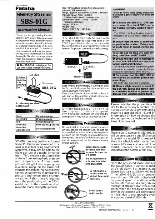
1M23N26718Futaba Telementry GPS sensor SBS-01G Instruction Manual感谢您购买Futaba的SBS-01G GPS传感器。
此传感器中,在与一个具有遥测功能的遥控器/接收器一起使用,用于指示向其所连接的项的距离/速度/高度。
为了最大限度地提高您的享受,并确保正确的感度,请仔细阅读本手册。
我们也鼓励您保留手册以备将来需要时使用。
SBS-01G 是专门为Futaba具有遥测回传功能的系统设计。
它用双面胶带粘在模型上的向上光滑的一面LED Indication LED指示绿色正常状态绿色闪烁GPS未连接红色无信号绿色/红色设置插槽中slot绿色/红色交替闪烁不可恢复的错误Location 位置SBS-01G计算通过GPS来计算位置和速度。
不建议在室内环境中飞行使用,它也不能够确认模型的姿势(例如倒立等)。
该传感器通过大气压力和温度来计算高度。
大气压强会随着高度的增加而变低,使用这种传感器会估计你的高度。
如果大气压力和温度变化不能被确切的显示时,它需要一个较短的时间内,等待GPS 的定位被确定,在此期间,不要移动模型。
使用方法:GPS/带仪表的海拔高度传感器范围:[速度]大约0km/h~500km/h(~311英里/每小时)[海拔]大约-700M~+5500m (-766码~+6015码)---传感器规格[旅行车仪表]大约-150m/s~+150m/s (-336英里每小时-336英里每小时)长度:175毫米重量:11克电压:DC3.7V〜7.4V直流Wiring 连线SBS-01G只能用于有遥测功能的遥控器和提供S.BUS 2接口的接收机使用,使用前请查找遥控器和接收机的说明书来确认合适的接线方法。
Relative distance/altitude 相对距离/高度当电源接通时,数据会记为0m,它显示的距离或者高度它从这里开始改变。
即使你的飞机场的海拔很高,它将在0米处记录并显示从机场的高度差。
aruba-captive-portal的配置手册
rf dot11g-radio-profile "default"tx-power 20 调整功率aaa profile "default"initial-role trusted-ap 默认角色为trusted-ap(config-subif)#operstate up(config) #show datapath session table(config) #show datapath acl(config) #show ap activeconfig) #wlan ssid-profile(Aruba800-4) (config) #no spanning-tree 单臂关闭spanning-tree(Aruba800-4) (config) #adp discovery 用户和无线交换机不在一个交换机关闭adp disable Disableenable Enable(Aruba800-4) (config) #adp discovery disable(config) #operstate up 端口快速启动Aruba800-4) (config-if)#switchport trunk allowedvlan Set allowed VLANs when interface is in trunking mode (Aruba800-4) (config-if)#switchport trunk allowed vlan 70,71,721、wlan ssid-profile staff-ssid-profile :定义ssid配置文件1.1 essid staff :定义ssid下的essid2、wlan virtual-ap staff-vap-profile :定义virtual-ap的配置文件2.1 ssid-profile staff-ssid-profile :在virtual-ap下引用定义过的SSID配置文件2.2 vlan :把virtual-ap加入到要ssid所属的VLAN3、aaa profile staff-aaa-profile :定义AAA认证配置文件4、aaa server-group staff-servergroup :定义server-group配置文件4.1 auth-server internal :定义认证服务器为本地认证4.2 set role condition role value-of :定义角色需要对应的权限5、aaa authentication captive-portal staff-auth-profile :captive-portal配置文件5.1 server-group staff-servergroup :在引用定义过的server-group6、user-role staff-logon :定义用户登陆前权限的配文件6.1 access-list session logon-control :定义用户登陆前的权限6.2 access-list session captiveportal :定义用户登陆前的权限6.3 Captive Portal staff-auth-profile :引用定义过captive-portal配置文件7、user-role vip-role :定义用户成功登陆后的配置文件7.1session-acl allowall :赋予权限8、wlan virtual-ap staff-vap-profile :进入定义过的virtual-ap配置文件8.1 aaa-profile staff-aaa-profile :引用定义过的AAA配置文件9、ap-group default :定义ap-group,最好用默认的9.1 virtual-ap staff-vap-profile :引用定义过的Virtual-ap配置文件10、aaa profile staff-aaa-profile :进入定义过的AAA配置文件10.1 initial-role staff-logon :把initial-role改为定义过的用户登陆前的配置文件11、aaa authentication-server internal use-local-switch :定义认证SERVER为本地机12、local-userdb add username staff password 123456 rolevip-role :定义用户的登陆的用户名和密码及权限注意:如果是有线直接连在端口上的话要进行认证必须把连接口设为UNTRUSTED.同时在设定:进入aaa authentication wired后设定:profile (staff-aaa-profile) 为你设定认证的AAA profile。
RTU520产品系列520AOD01数据手册说明书

ApplicationAnalog control outputs for sequential or closed-loop control, dis-play instruments, measurement recorders etc. can be connected by the analog output board 520AOD01. The board 520AOD01has 2 output channels, which can be configured to different out-put voltage or current ranges.The module 520AOD01 is able to process the following types of signals:–analog setpoint commands–floating point setpoint commandsThe following output ranges can be configured independent per channel by on-board switches:–± 2.5 mA –± 5 mA –± 10 mA–± 20 mA (4... 20 mA)–± 1.25 V DC –± 2.5 V DC –± 5 V DC –± 10 V DCThe output format unipolar, bipolar or live zero (4 … 20 mA) can be configured by software parameters.Figure 1: Block diagram 520AOD01CharacteristicsAnalog outputsEach output has a digital to analog converter (DAC), which con-verts the digital value into an analog signal. The DAC has a res-olution of 11 bit plus sign.A received output value keeps stored until a new value is re-ceived. The output channels are set to 0 % after power on or restart of the communication module.The output channels are potential isolated from the power sup-ply, but not between the two channels.Power supply inputThe required power for the module is supplied via the RTU520 I/O bus connector. In addition 24 V DC (U E ) is required (e. g. from 560PSU40/41). This voltage U E has to be supplied from external and wired to the U E connector.I/O controller (IOC)The micro-controller on the module processes all time critical tasks of the parameterized processing functions. Moreover it carries out the interactive communication with the RTU I/O bus.All configuration data and processing parameters are loaded by the communication unit via the RTU I/O bus.In connection with an I/O adapter (e. g. 520ADD01) or the RTU520 communication unit the module is interfaced to the RTU520 I/O bus.During initialization and operation the module carries out a num-ber of tests. If a fault occurs it is reported to the communication unit. All fault conditions impairing the function of the module are displayed as common fault signal by a red LED. A failure of the module is detected by the communication unit.2 | 1KGT 150 813 V003 1 - Analog output520AOD01Technical dataIn addition to the RTU500 series general technical data, the fol-lowing applies:Output channels 520AOD01Outputs 2 analog outputs,potential isolated against power sup-plyConfigurable output range–± 2.5 mA–± 5 mA–± 10 mA–± 20 mA (4... 20 mA)–± 1.25 V DC–± 2.5 V DC–± 5 V DC–± 10 V DCload impedance max. 500 Ω (current output)min. 500 Ω (voltage output) Resolution11 bit + sign2000 digit = 100% factory adjusted Accuracy at 25 °C< 0.25 % (± 20 mA)Linearity error at 25 °C< 0.02 % (± 20 mA)Temperature drift (0... 70 °C)< 200 ppm/KSupply voltage input 24 V DC (U E)Input voltage range24 V DC (+/- 20%)Current consumption60 mACurrent consumption for power supplied via WRB bus5 V DC25 mA15 V DC--18 V DC--24 V DC--Signaling by LEDsERR (red)Common fault information for themoduleMechanical layoutDimensions35 mm x 98 mm x 117 mm (Width xHeight x Depth)Housing type Plastic housing (V-0), IP20, RAL 7035light grayMounting DIN rail mountingEN 50022 TS35: 35 mm x 15 mm or35 mm x 7.5 mm Mechanical layoutWeight0.13 kgConnection typeProcess connector 2 x 2 pole 5.08 mm pluggable screwterminals (included in delivery)0.2... 2.5 mm²/ AWG 24 - AWG 12Power supply input 1 x 2 pole 5.08 mm pluggable screwterminals (included in delivery)0.2... 2.5 mm²/ AWG 24 - AWG 12Insulation testsAC test voltageIEC 61000-4-16IEC 60870-2-1 (class VW3)2.5 kV, 50 HzTest duration: 1 minImpulse voltage withstand testIEC 60255-5IEC 60870-2-1 (class VW 3)5 kV (1.2 / 50 µs)Insulation resistanceIEC 60255-5> 100 MΩ at 500 V DCImmunity testElectrostatic dischargeIEC 61000-4-28 kV air (level 3) / 4 kV contact (level 2)Performance criteria ARadiated Radio-Frequency Electro-magnetic FieldIEC 61000-4-310 V/m (level 3)Performance criteria AElectrical Fast Transient / BurstIEC 61000-4-44 kV (level X)Performance criteria ASurgeIEC 61000-4-52 kV (level 3)Performance criteria AConducted Disturbances, induced byRadio-Frequency FieldsIEC 61000-4-610 V (level 3)Performance criteria ADamped oscillatory waveIEC 61000-4-182.5 / 1 kV (level 3)Performance criteria AEnvironmental conditionsNominal operating temperature range:Start up:Max. operating temperature, max.96h:EN 60068-2-1, -2-2, -2-14-25 ... +70 °C-40 °C+85 °CRelative humidityEN 60068-2-305 ... 95 %(non condensing)Ordering information520AOD01R00011KGT024500R0001Analog output520AOD01 - 1KGT 150 813 V003 1 | 34 | 1KGT 150 813 V003 1 - Analog output520AOD01Note:The specifications, data, design or other information contained in this document (the “Brochure”) - together: the “Information” - shall only be for information pur-poses and shall in no respect be binding. The Brochure does not claim to be ex-haustive. Technical data in the Information are only approximate figures. We re-serve the right at any time to make technical changes or modify the contents of this document without prior notice. The user shall be solely responsible for the use of any application example or information described within this document. The described examples and solutions are examples only and do not represent any comprehensive or complete solution. The user shall determine at its sole discretion, or as the case may be, customize, program or add value to the ABB products including software by creating solutions for the end customer and to assess whether and to what extent the products are suitable and need to be ad-justed or customized.This product is designed to be connected to and to communicate information and data via a network interface. It is the users sole responsibility to provide and continuously ensure a secure connection between the product and users or end customers network or any other network (as the case may be). The user shall es-tablish and maintain any appropriate measures (such as but not limited to the in-stallation of firewalls, application of authentication measures, encryption of da-ta, installation of anti-virus programs, etc) to protect the product, the network,its system and the interface against any kind of security breaches, unauthorized access, interference, intrusion, leakage and/or theft of data or information. ABB AG is not liable for any damages and/or losses related to such security breaches, any unauthorized access, interference, intrusion, leakage and/or theft of data or information.ABB AG shall be under no warranty whatsoever whether express or implied and assumes no responsibility for the information contained in this document or for any errors that may appear in this document. ABB AG's liability under or in con-nection with this Brochure or the files included within the Brochure, irrespective of the legal ground towards any person or entity, to which the Brochure has been made available, in view of any damages including costs or losses shall be exclud-ed. In particular ABB AG shall in no event be liable for any indirect, consequen-tial or special damages, such as – but not limited to – loss of profit, loss of pro-duction, loss of revenue, loss of data, loss of use, loss of earnings, cost of cap-ital or cost connected with an interruption of business or operation, third party claims. The exclusion of liability shall not apply in the case of intention or gross negligence. The present declaration shall be governed by and construed in ac-cordance with the laws of Switzerland under exclusion of its conflict of laws rules and of the Vienna Convention on the International Sale of Goods (CISG).ABB AG reserves all rights in particular copyrights and other intellectual property rights. Any reproduction, disclosure to third parties or utilization of its contents -in whole or in part - is not permitted without the prior written consent of ABB AG.© Copyright ABB 2014All rights reservedAnalog output520AOD01 - 1KGT 150 813 V003 1 | 5。
Raspberry Pi Zero 用户手册说明书
RASPBERRY PI 0User ManualTable of contents 468
What Is the Raspberry Pi ZeroSize ComparisonGet Started with the Raspberry Pi Zero9Installing Raspbian with Windows 10 Installing Raspian with a Mac 11 Hey, NOOBS, Flash This! 12 Pre-Installed SD Cards 13 Connecting the Cables13Getting the Pi Zero Online 14 Mouse and Keyboard Options 14 Should You Connect a Monitor or Not?15A Pi Zero Case16Adding Pins to the GPIO16What the Pi Zero Means for Projects17FM Radio 17 Home Automation with OpenHAB 17 Airplay Receiver 17 Build a Raspberry Pi iBeacon 17 A Raspberry Pi Media Center 17 Whether you were lucky enough to buy a magazine with one glued to the front, or you’ve patiently waited after buying the full kit online, the chances are that you’re now the proud owner of a $5 computer, the Raspberry Pi Zero.
This remarkable slimline iteration of the Raspberry Pi shares hardware attributes with the Raspberry Pi A+, while bringing affordable computing and projecting to anyone with around $5 in their pocket.
RAMAC雷达操作手册
瑞典玛拉地质科学仪器有限公司RAMAC/GPR地质雷达操作手册(3.0版本)北京鑫衡运公司目录1.RAMAC/GPR地质雷达介绍 (3)1.1概述: (3)1.2 控制单元 (4)1.3 不屏蔽发射机 (4)1.4 不屏蔽接收机 (5)1.5 屏蔽电子单元 (5)1.6 天线 (6)1.6.1 不屏蔽天线 (6)1.6.2 屏蔽天线 (6)1.6.3 孔内天线 (6)1.7 供电 (7)1.8 光缆 (7)1.9 通讯电缆 (7)1.10 测距装置 (8)1.11 天线架 (8)1.12 滑行器 (8)1.12.1 测量轮 (9)1.12.2 天线雪橇 (9)2.安装软件 (9)2.1 安装及设置 (9)2.2 所需硬件 (10)2.3 运行软件 (10)3.RAMAC/GPR的启动 (10)3.1 仪器的组装 (11)3.2 使用不屏蔽天线 (12)3.2.1 安装滑行器 (12)3.3 使用屏蔽天线 (13)3.4 使用孔内天线 (14)3.5 实施测量 (14)3.5.1 选择天线频率 (15)3.5.2 选择触发方式 (15)3.5.3 选择通讯参数 (15)3.5.4 设置显示参数 (16)3.5.5 采集数据 (16)4.数据采集 (17)4.1 选择天线频率 (17)4.2 采集数据 (17)4.2.1 用孔内天线采集(略) (17)4.2.2 改变参数/设置及采集时更改参数 (17)4.2.3 设置屏幕调色板 (22)5.数据的打印、回放、编辑 (23)5.1 打开数据文件 (23)5.2 显示设置 (24)5.3 数据打印 (24)5.4 批打印 (25)5.5操纵数据文件 (27)5.6 把数据输出到RIVIEW观察软件 (28)5.7 转成SEG-Y格式 (29)5.8 编辑数据 (29)5.9 输出数据 (30)5.10 用程序建立的文件 (30)6.数据滤波 (31)6.1 数据的批处理 (38)7.增加解释 (39)8.快速指令 (40)附录1 (44)附录2 (45)附录3 (52)1.RAMAC/GPR地质雷达介绍1.1概述:本节简要介绍RAMAC/GPR地质雷达是如何工作的。
山洋RS1伺服调试快速入门手册
点击“Close” 点击“Close”键
马达运行
点击“Exit” 点击“Exit”键,完成操作
自动调节响应设定
选择“ 0” 选择“Group 0”
点击“ 选择General 点击“Parameter ”选择General Parameter Setting 双击此行
更改响应值 设定值越大, 设定值越大,应答性就越高
00增量式编码器01绝对式编码器07半双工名称00电机编码器类型01主电源输入类型详细00推荐设置04推荐设置系统参数设置4系统参数页码00转矩控制模式0505控制模式设定选择控制模式0320bit21bit18bit19bit分辨率设置选择绝对式编码器的分辨率17bit名称详细绝对式编码器08位置环编码器设置选择位置环控制编码器方法00电机编码器cn2输入01速度控制模式02位置控制模式03速度转矩开关模式04位置转矩开关模式05位置速度开关模式外部编码器分辨率设置设置外部编码器的分辨率使用内置再生电阻02使用外置再生电阻再生电阻设置设定再生电阻的连接
编码线长度决定了编码器电源端口数量 --- 如下. . 10m / 32.8FT max. 编码器电缆长度 +5v DC 电缆 0v DC 电缆 连接 19pin 连接 20pin
25m / 82.0FT max. 连接 17 ,19pin 连接18 ,20pin
40m / 131.2FT max. 连接 12 ,17 ,19pin 连接 11 ,18 ,20pin
点击保存图标
点击“ Execute” 点击““ Execute”
点击”OK”完成操 点击”OK”完成操 ”OK” 作
速度点动 - 2
1. 选择此 项 点击“Exit” 2. 点击“Exit”更改运行速度
RDM1系列塑料外壳式断路器使用说明书
R D M1塑料外壳式断路器符合标准:GB/T 14048.2产品安装使用前,请仔细阅读使用说明书,并妥善保管,以备查阅。
警告:1 产品安装时必须装上防护罩或隔弧板,否则后果自负。
2 本断路器安装必须由具有专业资格的人员进行配线作业。
3 严禁湿手操作断路器,否则发生电击事故。
4 断路器因被保护电路发生故障(过载或短路)而分闸,必须查明原因,排除故障后,才能进行合闸操作。
5 断路器进行短路动作特性试验时,应使用经国家有关部门检测合格的专用测试装置,严禁利用相线直接触碰的试验方法。
注意:1 断路器安装场所应无爆炸危险、无腐蚀性气体,并应注意防潮、防尘、防震动和避免日晒。
2 安装前应检查铭牌上的技术参数是否符合使用要求,并手动操作断路器合、分3次,检验操作机构有无卡滞现象,并操作试验按钮,机构应可靠动作,确认完好无损后,方可安装。
3 为防止相间飞弧短路造成事故,应对进线端裸露导线及铜母线自绝缘基座起进行绝缘处理(150mm~200mm)。
4 断路器安装时,连接的电线应选择能承受相应载流量的铜导线,导线截面积参考值见表12。
5 板前接线的断路器可以安装在金属骨架或绝缘板上,板后接线的断路器应安装在绝缘板上。
6 断路器在每六个月进行一次检查,检查时应切断电源,操作手柄使断路器合、分3次,检查机构是否可靠;并检查断路器与安装板的绝缘电阻,同时清除外壳表层尘埃,保持良好绝缘,如果绝缘电阻小于10MΩ,则该断路器应及时更换。
1 用途及适用范围RDM1系列塑料外壳式断路器(以下简称断路器),是本公司采用国际先进技术设计开发的新型断路器。
该断路器具有体积小、分断能力高、飞弧短、抗震动的特点,是陆地及船舶使用的理想产品。
断路器额定绝缘电压800V(RDM1-80为500V),适用于交流50Hz/60Hz,额定工作电压至690V,额定电流至1250A的配电网络中,用来分配电能和保护线路及电源设备免受过载、短路和欠电压等故障的损坏。
- 1、下载文档前请自行甄别文档内容的完整性,平台不提供额外的编辑、内容补充、找答案等附加服务。
- 2、"仅部分预览"的文档,不可在线预览部分如存在完整性等问题,可反馈申请退款(可完整预览的文档不适用该条件!)。
- 3、如文档侵犯您的权益,请联系客服反馈,我们会尽快为您处理(人工客服工作时间:9:00-18:30)。
RMBA-01 用户手册
v
目录
第四章 – 编程 系统配置 . . . . . . . . . . . . . . . . . . . . . . . . . . . . . . . . . . . . . . . . . . . . . . . . . . . . 4-1
Modbus 接线配置 . . . . . . . . . . . . . . . . . . . . . . . . . . . . . . . . . . . . . . . . . . . 4-1 控制地 . . . . . . . . . . . . . . . . . . . . . . . . . . . . . . . . . . . . . . . . . . . . . . . . . . . . . . 4-1
目录
第一章 –序言
面向的读者 . . . . . . . . . . . . . . . . . . . . . . . . . . . . . . . . . . . . . . . . . . . . . . . . . . 1-1 准备工作 . . . . . . . . . . . . . . . . . . . . . . . . . . . . . . . . . . . . . . . . . . . . . . . . . . . . 1-1 本手册内容 . . . . . . . . . . . . . . . . . . . . . . . . . . . . . . . . . . . . . . . . . . . . . . . . . . 1-2 本手册中的术语 . . . . . . . . . . . . . . . . . . . . . . . . . . . . . . . . . . . . . . . . . . . . . . 1-3
附录 A– 技术数据 RMBA-01 . . . . . . . . . . . . . . . . . . . . . . . . . . . . . . . . . . . . . . . . . . . . . . . . . . . A-1 Fieldbus 连接 . . . . . . . . . . . . . . . . . . . . . . . . . . . . . . . . . . . . . . . . . . . . . . . . A-2
交货检查 . . . . . . . . . . . . . . . . . . . . . . . . . . . . . . . . . . . . . . . . . . . . . . . . . . 2-2 兼容性. . . . . . . . . . . . . . . . . . . . . . . . . . . . . . . . . . . . . . . . . . . . . . . . . . . . 2-3 保质期和责任 . . . . . . . . . . . . . . . . . . . . . . . . . . . . . . . . . . . . . . . . . . . . . . . . 2-3
端子名称 . . . . . . . . . . . . . . . . . . . . . . . . . . . . . . . . . . . . . . . . . . . . . . . . . . 3-2 配线图 . . . . . . . . . . . . . . . . . . . . . . . . . . . . . . . . . . . . . . . . . . . . . . . . . . . 3-3 总线终端器 . . . . . . . . . . . . . . . . . . . . . . . . . . . . . . . . . . . . . . . . . . . . . . . . 3-4
RMBA-01 用户手册
1-1
第一章 - 序言
本手册内容
本手册介绍了关于 RMBA-01 模块的配线、配置和使用 方面的信息。
安全须知 位于本手册的前几页。
第二章 – 概述 简要介绍了 RMBA-01 Modbus 适配器模 块,以及交货检查和产品保质期方面的信息。
第三章 – 安装 包含对该模块进行硬件设置、安装和接 线方面的指导信息。
vi
RMBA-01 用户手册
面向的读者 准备工作
第一章 - 序言
本手册面向的读者是那些负责调试和使用 ACS 800 变频 器中 RMBA-01 Modbus 适配器模块的用户。读者需要 具备基本的电气知识、电气接线经验以及传动单元操作 方面的知识。
在开始安装 RMBA-01 Modbus 适配器扩展模块之前, 传动单元应该已经安装完毕并且可以准备投用。 除了备齐常规的安装工具之外,还应准备传动单元手册, 这些手册含有本手册所没有的许多重要信息,因此需要 在安装过程中进行查阅。
第三章 –安装 安装 . . . . . . . . . . . . . . . . . . . . . . . . . . . . . . . . . . . . . . . . . . . . . . . . . . . . . . . 3-1 配线 . . . . . . . . . . . . . . . . . . . . . . . . . . . . . . . . . . . . . . . . . . . . . . . . . . . . . . . 3-2
RMBA-01 用户手册
iii
安全须知
ivLeabharlann RMBA-01 用户手册目录
安全须知
概述 . . . . . . . . . . . . . . . . . . . . . . . . . . . . . . . . . . . . . . . . . . . . . . . . . . . . . . . . . iii 安全须知总则 . . . . . . . . . . . . . . . . . . . . . . . . . . . . . . . . . . . . . . . . . . . . . . . . . . iii
传动单元和其相邻设备必须正确接地。 不要带电操作传动装置,在切断主电源之后,应该至少 等待五分钟,待中间回路电容放电完毕后再操作变频器、 电机或电机电缆。最好在进行工作之前检查变频器是否 放电完毕(使用电压表)。
在接通主电源时,无论电机是否运行,电机电缆端子都 处于危险高电压状态。 即使传动单元的主电源被切断,其内部仍会存在由外部 控制电路引入的危险电压,因此操作时应该倍加小心。 忽视这些安全规则,将会引起人身伤害或死亡。
安全须知
概述 安全须知总则
本章介绍了在安装和操作 RMBA-01 Modbus 适配器模 块时必须遵守的安全规则。
在操作和使用传动单元之前,务必阅读本章的内容。 除了仔细阅读下面的安全须知外,您还须阅读所使用型 号的传动单元的完整的安全须知。
警告 ! 所有关于传动单元的电气安装和维护工作只能由 具备资格的电气工程师来完成。
第六章 – 故障跟踪 安装问题 . . . . . . . . . . . . . . . . . . . . . . . . . . . . . . . . . . . . . . . . . . . . . . . . . . . . 6-1 传动参数设置 . . . . . . . . . . . . . . . . . . . . . . . . . . . . . . . . . . . . . . . . . . . . . . . . 6-1 PLC 编程. . . . . . . . . . . . . . . . . . . . . . . . . . . . . . . . . . . . . . . . . . . . . . . . . . . . 6-1 状态指示 LEDs . . . . . . . . . . . . . . . . . . . . . . . . . . . . . . . . . . . . . . . . . . . . . . . 6-2
ABB Drives
用户手册
Modbus 适配器模块 RMBA-01
销售热线 15589947512
Modbus 适配器模块 RMBA-01 用户手册
3ABD 00009819 REV A CN Based on:3AFE 64498851 REV A EN