S509 红外气体传感器数据手册_co2
COT 212-R 温度与二氧化碳传感器数据手册说明书
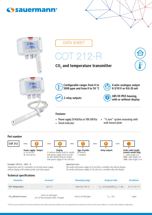
(1)Features• Power supply 24 Vdc/Vac or 100-240 Vac • Trend indicator• “¼ turn” system mounting withwall-mount plate4-wire analogue output 0-5/10 V or 0/4-20 mA Configurable ranges from 0 to 5000 ppm and from 0 to 50 °C ABS V0 IP65 housing, with or without display2 relay outputsPart numberExample: COT212 – BNS – RTemperature and CO 2 transmitter, 24 Vac/Vdc power supply, without display, with ambient probe and relay outputs Important note:The model with power supply of 24 Vac/Vdc is available only without display.The model with power supply of 100-240 Vac is available only with display.Power supply / Output B : 24 Vac/Vdc H : 100-240 VacDisplayN : without display (only for models with power supply of 24 Vac/Vdc)O: with display (only for models with power supply of 100-240 Vac)Type of probe D : Remote S : AmbientProbe cable length (remote model only) ( ): cable lentgh 2 m 05M: cable length 5 m 10M: cable length 10 mRelay outputsWarning: risk of electric shock 2 x 4-20 mA or 2 x 0-20 mA or 2 x 0-5 V or 2 x 0-10 V (4 wires)DOUBLE ISOLATION or REINFORCED ISOLATIONFeatures of housingAll dimensions are in millimeters.Probes technical specifications• Ambient probeRemote modelAmbient modelDimensionsConnections50-60 Hz 8 VA 0/4...20 mA / 0...5/10 V1234576l t a j e i e r r a e n t el t a j ei e r r a e n t e24 Vdc NL Alimentation 100-240 Vacor1. DIP switch (d)2. LCC-S software connection3. Relays4. Analogue outputs (a)5. F3.20* fuse6. Power supply terminal block (c)7. Cable glandsOn 100-240 Vac models, if a fuse protection is used for the power line, it is imperative to use delayed-action fuses in order to • •• N L Alimentation 24 Vacclasse II norme EN61558-2-6Pe N L ou230 Vacor230 VacNL Alimentation 100-240 Vac-+0-5/10 V0/4-20 mAAf cheur régulateur ou automate type passifAf cheur régulateur ou automate type passifSortie 4-20 mASortie 0-10 VPLC/BMS de tipo pasivoConfiguration of the transmittersIt is possible on the class 210 to configure all the parameters of the transmitter : units, measuring ranges, outputs, channels, calculation func-tions, etc, via different methods:• Keypad for models with display: a code-locking system allows to secure the installation (See class 210 transmitters user manual). • Software (optional) on all models: Simple user-friendly configuration. See LCC-S user manual.Sorties analogiques configurables: Configurable analogue output:It is possible to configure your own intermediary ranges in CO 2 and in temperature.Caution: the minimum difference between the high range and the low range is 20.37500 ppm 0 V 4 mA 2500 ppm 5000 ppm10 V 20 mANew range0 ppm0 V 4 mA 25005000 ppm10 V 20 mA3750MountingTo mount the transmitter, mount the ABS plate on the wall (drilling: Ø 6 mm, screws and pins are supplied).Insert the transmitter on the fixing plate (see A on the drawing beside). Rotate the housing in clockwise direction until you hear a “click” which confirms that the transmitter is correc-tly installed.MaintenancePlease avoid any aggressive solvent. Please protect the transmitter and its probes from any cleaning product containing formalin, that may beused for cleaning rooms or ducts.CalibrationOutputs diagnostic: With this function, you can check with a multimeter (or on a regulator / display, or a PLC / BMS) if the transmitter out-puts work properly. The transmitter generates a voltage of 0 V , 5 V and 10 V or a current of 4 mA, 12 mA and 20 mA.Certificate: Class 210 transmitters are supplied with adjusting certificates. Calibration certificates are available as an option.Options and accessoriesPrecautions for usePlease always use the device in accordance with its intended use and within parameters described in the technical features in order not to compromise the protection ensured by the device.Only the accessories supplied with the device must be used.All dimensions are in millimeters.F T _E N – C O T 212-R – 02/08/2021 – N o n -c o n t r a c t u a l d o c u m e n t – W e r e s e r v e t h e r i g h t t o m o d i f y t h e c h a r a c t e r i s t i c s o f o u r p r o d u c t s w i t h o u t p r i o r n o t i c e .。
红外气体探测仪IntelliDoX套装文件夹用户手册说明书

D o c k i n g M o d u l e50104991-166 E N -B 4©2018 H o n e y w e l l . A l l r i g h t s r e s e r v e d.Q u i c k R e f e r e n c e G u i d eI n t e l l i D o X ™S u i t e 110 4411-6 S t r e e t S EC a l g a r y , A l b e r t a C a n a d a , T 2G 4E 8T o l l -f r e e : 1-888-749-8878 w w w .h o n e y w e l l a n a l y t i c s .c o mA b o u t t h i s P u b l i c a t i o nT h i s p u b l i c a t i o n i s a q u i c k -s t a r t r e f e r e n c e g u i d e t o a s s e m b l i n g t h e I n t e l l i D o X D o c k i n g M o d u l e , a n d p r e p a r i n g i t f o r fi r s t u s e . E n s u r e t h a t y o u a r e f a m i l i a r w i t h t h e u s e o f p e r s o n a l g a s d e t e c t i o n d e v i c e s a n d a c c e s s o r i e s , a n d t a k e a p p r o p r i a t e a c t i o n i n t h e e v e n to f a n a l a r m c o n d i t i o n .F o r a d d i t i o n a l i n f o r m a t i o n r e g a r d i n g I n t e l l i D o X i n s t a l l a t i o n , c o n fi g u r a t i o n , o p e r a t i o n a n d m a i n t e n a n c e , r e f e r t o t h e I n t e l l i D o X U s e r M a n u a l a t h t t p s ://w w w .h o n e y w e l l a n a l y t i c s .c o m /e n /p r o d u c t s /I n t e l l i D o x A b o u t t h e I n t e l l i D o X D o c k i n g M o d u l eT h e I n t e l l i D o X D o c k i n g M o d u l e (‘I n t e l l i D o X ’ o r ‘I n t e l l i D o X m o d u l e ’)i s a n a u t o m a t i c b u m p t e s t a n d c a l i b r a t i o n d o c k i n g s t a t i o n f o r u s e w i t h p o r t a b l e g a s d e t e c t o r s m a n u f a c t u r e d b y H o n e y w e l l . T h e I n t e l l i D o X a u t o m a t i c a l l y p e r f o r m s e s s e n t i a l p r o c e d u r e s i n c l u d i n g s e n s o r i d e n t i fi c a t i o n , b u m p t e s t s , c a l i b r a t i o n s , a l a r m t e s t s a n d d a t a t r a n s f e r s . I t a l s o r e t a i n s a c u m u l a t i v e r e c o r d o f d e t e c t o r d a t al o g s t h a t a r e t r a n s f e r r e d t o i t s o n b o a r d m e m o r y .T h e I n t e l l i D o X c a n b e u s e d o n a t a b l e t o p o r o t h e r fl a t s u r f a c e . A b u i l t -i n r e t r a c t a b l e s t a n d c a n b e d e p l o y e d t o h o l d t h e I n t e l l i D o X u p r i g h t a t a n a n g l e t h a t i s s u i t a b l e f o r r o u t i n e u s e . I n t e l l i D o X m o d u l e s c a n a l s o b e m o u n t e d o n a w a l l o r o t h e r fl a t s u r f a c e .F o r a d d i t i o n a l i n f o r m a t i o n , r e f e r t o t h e U s e r M a n u a l .I n t e n d e d U s eU n l e s s o t h e r w i s e s p e c i fi e d a t t i m e o f p u r c h a s e , I n t e l l i D o Xm o d u l e s s h i p p e d f r o m H o n e y w e l l .• A r e f a c t o r y c o n fi g u r e d f o r u s e w i t h p o r t a b l e g a s d e t e c t o r s .• O p e r a t e a s s t a n d -a l o n e b u m p t e s t a n d c a l i b r a t i o n s t a t i o n s .• M a y b e c o n n e c t e d t o a n e t w o r k v i a E t h e r n e t c a b l e f o r e n h a n c e d a c c e s s t o a n d c o n t r o l o f a d m i n i s t r a t i v e a n dm a i n t e n a n c e t a s k s .• A r e c o m p a t i b l e w i t h P C C o n fi g u r a t i o n s o f t w a r e .• I f t h e I n t e l l i D o X m o d u l e o r a n y o f i t s p a r t s a r e d a m a g e d o r m i s s i n g , c o n t a c t H o n e y w e l l o r a n a u t h o r i z e d d i s t r i b u t o ri m m e d i a t e l y .N o r m a l O p e r a t i n g C o n d i t i o n sT h e I n t e l l i D o X i s d e s i g n e d t o b e s a f e u n d e r t h e f o l l o w i n g c o n d i t i o n s :• I n d o o r u s e o n l y• N o r m a l a t m o s p h e r e (20.9% O 2) t h a t i s f r e e o f h a z a r d o u s g a s• T e m p e r a t u r e r a n g e o f +10°C t o +35°C• R e l a t i v e h u m i d i t y o f 0% t o 50%I f t h e i n t e n d e d o p e r a t i n g e n v i r o n m e n t d o e s n o t m a t c h t h e s e c r i t e r i a , H o n e y w e l l r e c o m m e n d s t h a t y o u c o n s u l t a q u a l i fi e d p r o f e s s i o n a ls p e c i a l i s t p r i o r t o i n s t a l l i n g a n d u s i n g a n y I n t e l l i D o X m o d u l e s .T h i s e q u i p m e n t u s e s p o t e n t i a l l y h a r m f u l g a s f o r c a l i b r a t i o n s . T h e I n t e l l i D o Xm u s t b e a t t a c h e d t o a v e n t i n g s y s t e m o r b e u s e di n a w e l l-v en t i l a t e d a r e a .What’s in the BoxIntelliDoX Docking ModuleEach IntelliDoX Docking Module package contains one IntelliDoX module with a factory-installed nest. The power adapter, power cord, calibration gas tubing and exhaust tubing, are packaged separately as the IntelliDoX Enabler Kit. One Enabler Kit is required for each stand-alone IntelliDoX module.If the IntelliDoX module is damaged or if parts are missing, contact Honeywell or an authorized distributor immediately.IntelliDoX Enabler KitOne IntelliDoX Enabler Kit is required for each stand-alone IntelliDoX module. Each Enabler Kit contains:• Power supply and AC power cord appropriate to shipping destination.• Ethernet cable.• Calibration gas and purge gas tubing, cut to 1 meter (3.3 feet).• Quick connect fittings.• Exhaust tubing, cut to 4.57 meters (15 feet).• Inlet (purge) filter assembly.• IntelliDoX end plate.• Download PC Configuration software that supports your product from the Honeywell Analytics website. https:///en/products/IntelliDox If Enabler Kit parts are damaged or missing, or if additional Enabler Kits are required, contact Honeywell or an authorized distributor immediately.Copyright, Notices, TrademarksWhile this information is presented in good faith and believed to be accurate, Honeywell disclaims the implied warranties of merchantability and fitness for a particular purpose and makes no express warranties except as may be stated in its written agreement with and for its customers.In no event is Honeywell liable to anyone for any indirect, special or consequential damages. The information and specifications in this document are subject to change without notice.IntelliDoX is a trademark of Honeywell. Other brand or product names are trademarks of their respective owners.Configuration SoftwarePlease download PC configuration software on the IntelliDoX product page under the software tab on the Honeywell Analytics website. Symbol DefinitionsThis manual uses the following signal words, as defined by ANSI Z535.4-1998.Hazardous situation which, if not avoided, will result in death or serious injury. This symbol identifies the most extreme hazardous situations.Important Safety Information: Read First• To ensure personal safety, read Safety Information and Warnings before using the IntelliDoX.• Use the IntelliDoX only as specified by the manufacturer. Failure to do so may impair protection provided by the IntelliDoX.• The safety and security of any system or networkincorporating the IntelliDoX and its accessory components is the responsibility of the assembler of the system.• Follow all required National Electric Codes (NEC) and safety standards.Prepare for First UseTo ensure that the IntelliDoX module is ready for safe operation, you must attach the endplate, attach the purge inlet filter assembly, and connect the exhaust tubing before you connect power or attach a gas cylinder.Attach the EndplateEach IntelliDoX Enabler Kit contains one endplate. To prevent gas leaks, the end plate must be attached and locked with the lock latch arm before connecting power supply or connecting gas cylinders. The end plate must remain securely latched at all times during operation. If the end plate is detached during operation, disconnect power and replace the end plate immediately.• Unhook and lift latch arm.• Attach end plate.• Lower and lock latch arm.This symbol indicates that the product must not bedisposed of as general industrial or domestic waste. This product should be disposed of through suitable WEEE disposal facilities. For more information about disposal of this product, contact your local authority, distributor or the manufacturer.Product Configuration Software IntelliDoX BWClip Fleet Manager/SafetySuite DC IntelliDoX BW MicroClip Fleet Manager/SafetySuite DC IntelliDoX BW Clip4Fleet Manager/SafetySuite DC IntelliDoX BW Ultra Fleet Manager/SafetySuite DCIntelliDoX BW SoloSafetySuite DCAt a Glance Top viewBottomLeft RightTouchpad and buttonsLCD BacklightConnect the Purge Inlet Filter AssemblyEach IntelliDoX Enabler Kit contains one purge inlet filter assembly. Unless otherwise specified, the purge inlet is configured to use ambient air in a fresh air environment with a normal atmosphere of 20.9% O 2 that is free of hazardous gas . Ensure that the purge inlet filter assem-bly is attached before using the IntelliDoX module. You may attach an extension tubing to the filter assembly to draw ambient air from an adjacent fresh air environment.1. Ensure that the filter assembly is free of obstructions and defects.2. Connect the filter assembly to the purge inlet.3. If necessary, attach an extension tubing to the filterassembly to draw ambient air from an adjacent fresh air environment.Connect the Exhaust TubingEach IntelliDoX Enabler Kit includes one exhaust tubing that is 4.57 meters (15 feet) long.1. Inspect the exhaust tubing to ensure that it is free ofobstructions and defects.2. Connect the exhaust tubing to the exhaust outlet.3. Ensure that the exhaust tubing is not connected to anegative pressure system, or obstructed in any way.Connect the PowerEach IntelliDoX Enabler Kit contains one power supply and AC power cord. Use only the power supply provided in the Enabler Kit to connect the IntelliDoX Docking Module to an appropriate electrical power outlet. When the power is connected, the IntelliDoX activates and a self-test is performed.1. Connect the AC power cord to the power supply2. Connect the power supply to the IntelliDoX power port.3. Plug the AC power cord into a suitable wall outlet.4.When the power is connected, the IntelliDoX LCD activates and a self-test is performed.NOTICETo prevent the corruption or loss of data and/or software and/orfirmware, do not deactivate the equipment while performing datalog transfers, bump tests, calibrations or other operations.Charge a DetectorUse the IntelliDoX to charge detectors fitted with rechargeable batteries. For more information on battery maintenance, refer to the detector manual.1. Charge only in a normal environment that is 20.9% O2 andfree of hazardous gas. Do not operate the docking module in a hazardous area. Failure to adhere to this guideline can result in possible personal injury and/or property damage.2. Deactivate the detector.3. Insert the detector into the IntelliDoX module.4. Battery charging begins immediately. Battery charging isdisabled during bump test and calibration procedures.Once tests and other routines are completed, you may leave the detector in the module for charging. If the detector is activated, the module will deactivate it after 10 minutes of inactivity. When charging is complete, remove the detector. Do not store the detector in the module.Prepare for Bump Tests and CalibrationsThe IntelliDoX module is factory-configured for use with portable gas detectors. Gas inlets are configured at the factory. Inlet con-figurations cannot be altered. The IntelliDoX Enabler Kit includes quick connect fittings and calibration tubing cut to the minimum recommended length of 1 meter (39 inches). Use only tubing that is between 1 meter (39 inches) and 10 meters (33 feet) in length when you connect gas cylinders to an IntelliDoX module.Connect Calibration Gas1. Connect a demand flow regulator to the calibration gascylinder.2. Use the quick connect fittings and calibration gas tubingto connect the calibration gas cylinder to the gas.Bump TestBump test is a procedure that confirms a detector’s ability to respond to target gases by exposing the detector to gas concentrations that exceed its alarm setpoints.If AutoBump on Insertion is set using PC configuration software, then bump test starts automatically when IntelliDoX recognizes the detector. If AutoCal onOverdue Sensors is enabled and if a calibration is also due, then no bump test is performed. Instead, calibration starts automatically when the detector is recognized.1. Insert a detector.2. Press and on the keypad to move to Bump test mydetector on the IntelliDoX user menu.3. Press to select Bump Test. The LCD screen backgroundchanges to yellow and the bump test progress screen is displayed.4. The bump test begins. Test sequence progress screens aredisplayed while the tests are performed.5. If AutoDownload Datalog is set using PC configurationsoftware, detector datalogs are automatically transferred to IntelliDoX.Bump Test PassWhen the bump test is successful, LCD screen background changes to green and Bump test passed message is displayed. Alarm response and sensor response test items are checked.Press to return to IntelliDoX usermenu.Bump Test FailWhen the bump test fails, LCD screen background changes to red and Bump test failed message is displayed. Failed alarm response and/or sensor response test items are marked with .If the AutoCal on Failed Bump is set using PC configuration software, calibration automatically begins.CalibrationCalibration is a two-step procedure that determines the measurement scale for the detector’s response to gas. In the first step, a baseline reading is taken in a clean, uncontaminated environment. In the second step, the sensors are exposed to known concentrations of gas. The detector uses the baseline and known gas concentrations to determine the measurement scale.Calibration Guidelines1. Calibrate only in a normal environment that is 20.9% O 2and free of hazardous gas. Do not operate the docking module in a hazardous area. Failure to adhere to this guideline can result in possible personal injury and/or property damage.2. Use only premium grade calibration gases and cylindersthat are approved by Honeywell, and supplied byHoneywell or an authorized distributor. The calibration gases must meet the accuracy of the detector. For more information, refer to the User Manual.3. Do not use a gas cylinder beyond its expiration date.4. All calibration cylinders must be used with a demand flowregulator and must meet these maximum inlet pressure specifications. Disposable cylinders: 000 psig/70 bar, refillable cylinders: 03000 psig/207 bar5. Do not calibrate the detector during charging orimmediately after charging.6. Calibrate the sensor if ambient gas readings vary duringstartup.7. Calibrate a new sensor before use. Allow the sensor tostabilize before starting calibration.8. Used sensor: wait 60 seconds 9. New sensor: wait 5 minutes10. When calibrating the same gas detector multiple times,wait 10 minutes between calibrations to allow the sensor to stabilize.11. If a certified calibration is required, contact Honeywellor an authorized distributor.Calibrate a DetectorIf AutoCal on Overdue Sensors is set using PC configuration software and sensors are overdue, then calibration starts automatically once IntelliDoX recognizes the detector.1. Insert a detector.2. Use and to move to Calibrate my detector on the IntelliDoX user menu.3. Press to select Calibrate my detector. The LCD screen background changes to yellow and the calibration progress screen is displayed.4. Calibration begins. Progress screens are displayed while the tests are performed.5. If AutoDownload Datalog is set using PC configuration soft ware, detector datalogs are automatically transferred to IntelliDoX.Calibration PassWhen the calibration is successful, LCD screen background changes to green and Calibration passed is displayed. Alarm response and sensor response test items are checked. Press to return to IntelliDoX user menu.Calibration FailWhen the calibration fails, LCD screen background changes to red and Calibration failed is displayed. Failed alarm response and/or sensor response test items are marked with.What do you need to do?Bump test my detectorSerial Number:CNXAAWhat do you need to do?Calibrate my detector Serial Number:CNXAABump test failedAlarm response:Sensor response:Acoustic Visual Vibrator COSerial Number:CNXAABump test passedAlarm response:Acoustic Visual Vibrator COSerial Number:CNXAASensor response:Calibration passedAlarm response:Acoustic Visual Vibrator COSerial Number:CNXAASensor response:54321。
二氧化碳传感器 CO2

IRceL ® CO2Technical SpecificationsNon-Dispersive Infra-Red (NDIR)0-5% vol. Carbon DioxideWithin ± (0.1% vol CO 2 + 4% ofconcentration)<35 Seconds< ±0.003% CO 2< ±0.075% CO 2See Operating Principles OP17Product DimensionsAll dimensions in mm All tolerances ±0.15mm unless othewise statedIMPORTANT NOTE:Connection should be made via PCB sockets only. Soldering to the pins will seriously damage your sensor.All performance data is based on conditions at 20°C, 50%RH and 1013mBar, using CityTechnology recommended circuitry. For sensor performance data under other conditions, refer to the Characterisation Note and Operating Principles.Carbon Dioxide (CO 2) Gas SensorPart Number: IRCEL-CO2RMEASUREMENTOperating Principle Measurement Range Accuracy (-20°C to +50°C)Response Time (T 90)Repeatability:Zero 5% CO 2Linearity 3-5 VDC, 3.3 V to utiliseEEPROM calibration<100 mW at 3.3 V2 Hz, 50% duty cycle0.005% CO 2 at zero0.15% CO 2 at range<10 SecondsELECTRICALSupply Voltage Power Consumption Recommended Lamp Frequency Minimum Resolution Warm-up Time Stainless Steel (see back page)23 g AnyMECHANICALHousing Material Weight Orientation General Purpose Portable /Fixed CO 2 Detection-20°C to +50°C0 to 99% RH (non-condensing)700 to 1300 mBar withcompensation ENVIRONMENTALTypical Applications Operating Temperature Range Operating Humidity Range Operating Pressure Range < 80 ppm CO 2 per month-20°C to +50°C> 5 years12 months from date of despatch LIFETIMELong Term Zero Drift Recommended Storage Temp MTBF Standard Warranty Key Features & Benefits:•Integrated thermister for accurate temperature compensation •EEPROM programmed with sensor specfic performance characteristics •Compact SizePin Function 1Lampreturn 2Lamp +5V 3+5V pyro supply 4Detec tor output 5Referenc e output 6Thermis tor output 70V py ro supply中国 北京赛斯维测控技术有限公司北京市朝阳区望京西路48号金隅国际C座1002电话:+86 010 8477 5646传真:+86 010 5894 9029邮箱:i angarmy@Instructions specific to hazardous area installations(reference European ATEX Directive 94 / 9/ EC, Annex II, 1.0.6.)The following instructions apply to equipment covered by certificate number Sira 04ATEX1084X;1.The equipment may be used with flammable gases and vapours with apparatus groups IIA,IIB and IIC and with temperature classifications T1, T2, T3 and T4.2.The equipment is certified for use in ambient temperatures of -20ºC to +55ºC.3.The equipment has not been assessed as a safety related device (as referred to by Directive94 / 9 / EC Annex II, clause 1.5).4.Installation of the equipment shall be carried out by suitably trained personnel in accordancewith the applicable code of practice (e.g. EN 60079-14)5.Inspection and maintenance of this equipment shall be carried out by suitably trainedpersonnel in accordance with the applicable code of practice (e.g. EN 60079-17).6.Repair of this equipment shall be carried out by suitably trained personnel in accordance withthe applicable code of practice (e.g. EN 60079-19).7.Special conditions for safe use7.1. The IRceL is designed to be connected to a gas detector which shall provide an intrinsicallysafe supply and having a maximum output power (Pmax) not greater than 1.4watt.7.2.Because the IRceL has not been proven to withstand the impact and drop tests prescribedin EN 60079-0:2006, clauses 26.4.2 and 26.4.3, additional protection shall be provided toensure that it cannot be subjected to such mechanical stresses.Approval Body:SIRA CERTIFICATION SERVICETest Standard:EN 60079-0:2006 General RequirementsEN 60079-1:2007 Flameproof Enclosures "d"EN 61241-0:2006 Electrical Apparatus for use in the presence of Combustible DustPart 0 : General Requirements.EN 61241-1:2004 Electrical Apparatus For use in th epresence of Combustible DustPart 1 : Protection of Enclosures "td"Product Categories:ExdI/IIC T4 (Tamb-20°C to +55°C),Pmax = 1.4W MbGbExtIIICIP6xDbII2GD/IM2 0518Certificate Number:Sira 04ATEX1084XApproval Body:UNDERWRITERS LABORATORIES INC®Test Standard:UL913CSA.C22.2 No 157Product Categories:Class 1, Division 1, Groups A, B, C, DFile Number:E180262Product Approval8.The certification of this equipment relies upon the following materials used in its construction;Enclosure material:either303 stainless steel, which contains less than 6%magnesiumor304 stainless steel, which contains less than 6% magnesiumFlame arrester:316 stainless steel meshCement:CW2248/HY956ENManufacturer Ciba-GeigyType of compound Epoxy resinColour Beige (natural)Filler type and %55.2% trihydrated Al2O3Other additives8.3%Surface treatments NoneTemperature index170°CCity Tech reference RM 497If the equipment is likely to come into contact with aggressive substances, then it is the responsibility of the user to take suitable precautions that prevent it from being adversely affected, thus ensuring that the type of protection is not compromised.Aggressive substances: e.g. acidic liquids or gases that may attack metals, or solventsthat may affect polymeric materials.Suitable precautions:regular checks as part of routine inspections or establishingfrom the material's data sheet that it is resistant to specificchemicals.9.The IRceL is available in several formats depending upon the optical filter and componentsemployed. The Certification marking is shown below using the IRceL CH4 label as an example:Every effort has been made to ensure the accuracy of this document at the time of printing. In accordance with the company’s policy of continued product improvement City Technology Limited reserves the right to make product changes without notice. No liability is accepted for any consequential losses, injury or damage resulting from the use of this document or from any omissions or errors herein. The data is given for guidance only. It does not constitute a specification or an offer for sale. The products are always subject to a programme of improvement and testing which may result in some changes in the characteristics quoted. As the products may be used by the client in circumstances beyond the knowledge and control of City Technology Limited, we cannot give any warranty as to the relevance of these particulars to an application. It is the clients’ responsibility to carryout the necessary tests to determine the usefulness of the products and to ensure their safety of operation in a particular application.Performance characteristics on this data sheet outline the performance of newly supplied sensors. Output signal can drift below thelower limit over time.。
二氧化碳CO2传感器模组1
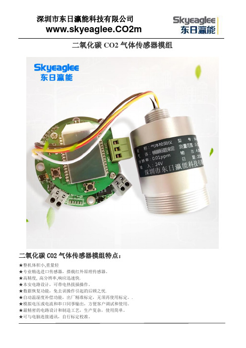
二氧化碳CO2气体传感器模组
二氧化碳CO2气体传感器模组特点:
★整机体积小,重量轻
★专业精选进口传感器,搭载红外原理传感器。
★高精度, 高分辨率,响应迅速快.
★本安电路设计,可带电热拔插操作。
★数据恢复功能,免去误操作引起的后顾之忧.
★自动温湿度补偿功能,出厂精准标定,无须再使用标定。
. ★模拟电压或电流和串口同事输出,方便客户调试和使用。
★最精密的电路设计和制造工艺,生产复杂,使用简单。
★可与电脑连接通讯,自行标定校准。
★自带零点微调功能,方便选定参照数据。
★低功耗产品,可异动电源供电可大量用于分析仪仪器,大气,环境无人机监测。
二氧化碳CO2气体传感器模组结构尺寸图:
二氧化碳CO2气体传感器模组直视图和PIN脚定义图:
二氧化碳CO2气体传感器模组串口和电压采集接线定义图:
二氧化碳CO2气体传感器模组I2C接线定义图:
二氧化碳CO2气体传感器模组RS485接线定义图:
二氧化碳CO2气体传感器模组量程选择图表
二氧化碳CO2气体传感器模组应用场所:
医药科研、学校科研、制药生产车间、烟草公司、环境检测、楼宇建设、消防报警、污水处理、石油石化、化工厂、冶炼厂、钢铁厂、煤炭厂、热电厂、锅炉房、加气站、垃圾处理厂、隧道施工、输油管道、航空航天、工业气体过程控制、室内空气质量检测、地下燃气管道检修、危险场所安全防护、军用设备检测等。
NAP-508 气体传感器技术说明书

100525NAP-508气体传感器技术说明书(电化学式一氧化碳传感器)根本传感器技术株式会社〒168-0072東京都杉並区高井戸東4-10-9TEL. : 03-3333-2760FAX. : 03-3333-7344E-mail : ****************.jpURL : http://www.nemoto.co.jpNAP-508是一款新开发的一氧化碳传感器,较之于NAP-505,具有更长的寿命。
除了外壳颜色用棕红色标示外,外形尺寸和NAP-505一致。
检知原理和特性、使用注意事项请参照NAP-505的相关资料。
以下为NAP-508的特性、 优势、寿命方面做一下介绍。
1. 规格・工作温湿度 温度 : -20 ― +50℃ 湿度 : 15 – 90%RH ・气压 : 1 ± 0.1atm ・推荐电阻 : 10Ω ・推荐保管温度 : 0 – 20℃ ・推荐库存时间: 6个月以内2. 特性・检查对象气体 : CO 一氧化碳 ・量程 : 0 – 2000ppm 最大量程 :1%VOL・输出电流 : 20 ± 5nA/ppm.CO ・基线偏移 : ±5ppm 以下 ・反应时间 : T90 45秒以内 ・零点温飘(-20-50℃) : 10ppm 以下 ・衰减性 : 3%以下/年 ・同日重复性 : ±2%以内3. 各种特性 3-1. 线性120010008006004002000出力電流(μA )ガス濃度(ppm)53-2.3-3.温度(℃):基準温度 20℃-20 -10 0 10 20 30 40 50 変化率(%) 75 82 89 95 100 103.5 106 108 补偿后的变化96 99.4 101.1 101.8 101.8 100.7 99.8 99.3率;(%)**:使用推荐线路上的热敏电阻注意:用推荐线路的热敏电阻,基线不能补偿3-4.4.外形名称材質・規格外盖子本体过滤纸针脚材質:PPO*、 色:棕红色材質:PPO、 色:黑色PTFE**(多层压制)φ9.5 φ0.5镍合金(50FN)****:苯醚**:聚四氟乙烯***:FeNi50%镍合金ピン配置5.推荐电路6.干扰感应气体实验气体浓度(ppm) CO气体浓度换算值(ppm) 一氧化碳100100氢气25080甲烷50000丙烷25000CO2 50000SO2 250H2S 100NO 300NO2 30<10NH3 1000***乙酸乙酯2000***二氯甲烷2000***庚烷5000***甲苯2000***IPA2000***乙醇2000<30*六甲基二硅氧烷100**曝露時間:* 30 minutes** 40 minutes *** 2 hours7.耐久试验7-1. 高温試験实验条件: 50℃、40%RH 1000小时暴露试验后输出值变化: ±15%以内7-2. 高温高湿实验实验条件: 50℃、90%RH 1000小时暴露试验后输出值变化: ±10%以内7-3. 低温试验实验条件: -20℃1000小时暴露试验后的输出值变化: ±10%以内7-4. 低湿度实验实验条件: 25℃、20%RH 1000小时暴露试验后输出变化: ±10%以内7-5. 冷热循环实验实验条件: -20℃和50℃环境中分别放置30分钟循环10次试验后输出变化: ±10%以内8.机械强度8-1. 耐震性将传感器安X/Y/Z轴各个方向,以1.5mm 10~55~10Hz (扫描时间:1分钟)各振动2个小时。
SGX Europe Sp. z o.o. 荷兰气体传感器系列数据手册说明书

___________________________________________________________________________________________Whilst SGX has taken care to ensure the accuracy of the information contained herein it accepts no responsibility for the consequences of any use thereof and also reserves the right to change the specification of goods without notice. SGX accepts no liability beyond the set out in its standard conditions of sale in respect of SGX Europe Sp. z o.o. Building 11Ligocka St. 103, 40-568 Katowice, PolandT: +48 (0) 32 438 4778E:**************************IR15 Dual Gas Series DatasheetInfrared Dual Gas Sensor for Hazardous Environments(Portable and Fixed Systems)The SGX infrared sensors use the proven Non-Dispersive Infrared (NDIR) principle to detect and monitor the presence of gases. With an infrared source and specific filtering on the pyroelectric detectors mounted inside the optical/gas cavity, individual gases or types of gas can be identified and their concentrations determined.These sensors are suitable for reliable monitoring of gas levels in general safety applications where the sensor size is restricted and require a flameproof enclosure for hazardous environments.The IR15 Series contain two active detector elements for simultaneous monitoring of Carbon Dioxide and Methane or Hydrocarbon mixtures in the same size housing as some of the single gas sensors from the IR1xxx series sensors, making the sensor more cost effective than two separate sensors.APPLICATIONS∙ Oil & Gas∙ Petrochemical ∙ Biogas∙Wastewater ∙ Utilities ∙ Steelworks∙ Confined Space Entry ∙ Indoor Air QualityFEATURES∙ For detection of the following gases:o Carbon Dioxide & Hydrocarbons, o Hydrocarbons Mixtures ∙Gas concentration ranges:o 0 - 5% Carbon Dioxide(also suitable for 0 to 0.5%v/v) o 0 - 100% Carbon Dioxide(also suitable for 0 to 10%) o 0 - 100%v/v Hydrocarbons(also suitable for 0 to 100%LEL)∙ 19mm sensor height∙ Embedded thermistor for improved temperature compensation∙ Diffused gas sampling via mesh ∙ Low power∙ Reference channel for self-compensation∙ Special gold plated optical gas cavity for stable signal levels∙ Operational in varying temperature, pressure and humidity∙ Fast response∙ Rugged stainless steel construction ∙ No moving parts∙ Immunity from ‘poisoning’∙Reliable fail-safe operation∙Certified: ATEX, IECEx, CSA and ULOPERATIONTo operate, the sensors must be interfaced to a suitable circuit for power supply, output amplification and signal processing. Sensor outputs require linearisation and compensation for ambient temperature variation using algorithms in the system firmware. This is necessary for sensors to meet their full performance specification. An embedded temperature sensor facilitates this compensation on certain types. Further compensation for pressure changes can also be made in an algorithm, provided there is a suitable input from a pressure sensor.A set of Application Notes is available from the SGX Sensortech Ltd website, to explain more about NDIR gas sensing and provide advice for the end-user on interfacing the sensors and processing signals.TECHNICAL SPECIFICATIONCONFIGURATIONSThe Highest Concentration Range is the highest range the sensor is suitable. The Lowest Concentration Range is the lowest range the sensor is suitable. The use of the sensor beyond these ranges will affect the sensor’s performance.IR15TTThe IR15TT can be used in all applications for general monitoring of both relatively low concentrations of carbon dioxide and simultaneous %LEL and %v/v concentrations of Group II hydrocarbons, including benzene. The sensors contain a broadband hydrocarbon detector which are cross sensitive to most hydrocarbons and can therefore be calibrated to a specific target gas or a number of gases that can then be selected in the configuration of the customer’s gas measurement instrument.IR15TT-MThe IR15TT-M is very similar to the IR15TT except that a narrowband hydrocarbon detector is used. The sensor can still be used to monitor the same levels of carbon dioxide and hydrocarbons but are unsuitable for the detection of benzene. The narrowband detector also has a slightly lower response to humidity than the IR15TT, but is generally more cross-sensitive to other hydrocarbons.IR15TT-RThe IR15TT-R was designed specifically for Biogas applications for the simultaneous detection of carbon dioxide up to 100%v/v and %LEL and %v/v concentrations of hydrocarbons, but can be potentially used for other applications. The IR15TT-R contains the narrowband detector which is unsuitable for the detection of benzene.IR15TT-DThe IR15TT-D is fitted with both the narrowband and broadband hydrocarbon detectors with differing centre wavelength and bandwidth to potentially differentiate between hydrocarbons. The sensor was designed for the gas instruments being used by utilities companies to help differentiate between different compositions of natural gas.HANDLING PRECAUTIONS1. Do not allow sensors to fall on the floor. This could cause IR Source filament breakage, damage to the pins and the gasentrance aperture.2. Do not apply mechanical force against the gas entrance aperture.3. Do not immerse sensors in water or other fluids.4. Protect the gas entrance aperture against dust ingress and sprayed materials.5. Anti-static handling precautions must be taken.PERFORMANCEFor test purposes, all data taken using the following conditions:- Performance as tested in the SGX IR-EK2 Evaluation Kit directly after calibration.- SGX linearisation and temperature compensation algorithms applied; see Infrared Sensor Application Notes.- IR Source Voltage 5V, square wave, at 4 Hz and 50% duty cycle. Running the IR Source at 3V will decrease performance due to lower output signals.- Ambient temperature (20°C) and pressure (101 kPa).- All gases diluted in dry nitrogen.- Performance for the Hydrocarbons refers to Methane only. Most other hydrocarbons will have an improved performance.- Performance data is the same for the supported IR Source variants (“_1” variants).- Refer to Application Notes for more information.(2) Production Test Limits, using standard test gases of Dry Nitrogen, 2%v/v Carbon Dioxide and 5%v/v Methane, where appropriate . (3) A 0.30 absorbance is equivalent to a 30% decrease in the Active peak-to-peak output.(4)The minimum detection level is the smallest detectable change in concentration based upon a 2 sigma variantion. The best detectable change occurs at 0% gas concentration due to the non-linear output of the detector (see Fractional Absorbance Curves).(5) Performance for most hydrocarbons will be better than for methane for equiavlent concentrations, as methane is one of the lower sensitive gasescompared to other hydocarbons.(6) After linearisation using the recommended method of linearisation and based upon a calibration gas with a concentration >75% of the full-scale. (7) Using average Alpha and Beta coefficients based upon test data from the instrument in which the sensor is being tested. Refer to ApplicationNotes for information on calculating Alpha and Beta coefficients. Accuracy can be improved by measuring each sensor over temperature to define specific Alpha or Alpha & Beta coefficients.(8) After sensor stabilisation and over a period of 8 hours. (9) Difference in response when changed from 0 %RH to 90 %RH.(10) Sensors can be used over a greater ambient pressure using pressure compensation of the concentration. An external pressure sensor will berequred for this.FRACTIONAL ABSORBANCE CURVESThese show the typical sensitivity versus concentration before linearisation for the range of gases. For further explanation, refer to the Infrared Sensor Application Notes.Primary Target GasesNote: Both IR15TT-D channels have a similar response to methane but different responses to other alkanes (see table below).Relative Absorbance of Narrowband and Broadband Detectors to AlkanesMethane 5%v/v Ethane (0.5%v/v) Propane (0.35%v/v) Narrowband1.00 0.82IR15TT-D / IR15TT-MBroadband 1.00CERTIFICATIONSCSAULATEXIECEXINSTRUCTIONS SPECIFIC TO HAZARDOUS AREA INSTALLATIONS(Ref: EU ATEX Directive 2014/34/EU)1. The IR15xx Series Gas Sensing Heads are component-approved only and may not be used as stand-alone items in ahazardous area without further protection.2. The IR15xx Series Gas Sensing Heads shall be protected in service. The Sensing Head shall be mounted in a protectiveenclosure such that an impact of 7 J in accordance with IEC 60079-0:2007 clause 26.4.2 from any direction shall not cause the impact head to make contact with the Sensing Head.3. The thermal resistance of the IR15xx Series Gas Sensing Heads does not exceed 25 K/W. This shall be taken into accountwhen considering its surface temperature and the temperature classification of the equipment into which it is to be incorporated. Tests indicated that an internal ignition raises the temperature of the mesh by a further 4.2 K (including a 1.2 safety factor).4. The IR15xx Series Gas Sensing Heads have not been assessed as a safety device (EHSR 1.5).5. There are no user-serviceable parts in the component.6. The end-user/installer shall be aware that the certification of the IR15xx Series Gas Sensing Heads relies on the followingmaterials used in its construction, which are suitable for most common applications:Enclosure .................................. Stainless steel Mesh ......................................... Stainless steel Bushing ..................................... Epoxy resinIn accordance with the Note in EN60079-0:2006 clause 6.1, the end-user/installer shall inform the manufacturer of any adverse conditions that the IR15xx Series Gas Sensing Heads may encounter. This is to ensure that the IR15xx Series Gas Sensing Heads are not subjected to conditions that may cause degradation of these materials. 7. The IR15xx Series Gas Sensing Head is only certified for use in ambient temperatures between -20°C and +55︒C andshould not be used outside this range.8. The maximum input power of the IR15xx Series Gas Sensing Head shall not exceed 2.5 W.9. The IR15xx Series Gas Sensing Heads are dust-proof (IP5x) but offers no protection against the ingress of water. Whereprotection in excess of IP50 is required, the apparatus into which the IR15xx Series Head is installed shall provide the necessary ingress protection (for example by fitting an external semi-permeable membrane).OUTLINE(All dimensions in millimetres; dimensions without limits are nominal)ConnectionsOutline NotesPin Connection 1. Body dimensional tolerances ±0.1 mm. Pindimensional tolerances as indicated.1 IR Source2 Reference Detector Output3 IR Source Return2. IR15xx Series sensors are designed to press-fit intoPCB sockets. The end-user should choose a socket to accommodate the full sensor pin length. This will ensure a stable mechanical location as well as good electrical contact. SGX Sensortech Ltd recommend the Wearns Cambion type 450-1813-01-03-00 single-pole solder mount socket with through hole, or a suitable equivalent.4 Active 1 Detector Output (CO2 for IR15TT / IR15TT-M / IR15TT-R; Narrowband Hydrocarbon for IR15TT-D)ACCESSORIESDust Membrane (DPP702964BA)Material PTFEAir Flow ≥6.8 l/hr/cm2(∆p 10mbar) Water Intrusion Pressure ≥210 mbarLaminated PTFE Thickness 0.28 mm (nominal)。
Sensirion SGP30 多像素气体传感器数据手册说明书
Preliminary Datasheet SGP30Important Note:▪All specifications are preliminary and are subject to change without prior notice.▪Characterization and qualification of this product is ongoing.SGP30Sensirion Gas Platform Preliminary Datasheet▪ MEMS metal-oxide gas sensor for measuring volatile organic compounds (VOCs) ▪ Outstanding long-term stability▪ I 2C interface with TVOC and CO 2eq output signals ▪ Very small 6-pin DFN package: 2.45 x 2.45 x 0.9 mm 3 ▪ Low power consumption: 48 mA at 1.8V ▪ Tape and reel packaged, reflow solderableBlock DiagramFigure 1 Functional block diagram of the SGP30.Product SummaryThe SGP30 is a digital multipixel gas sensor designed for easy integration into air purifier, demand-controlled ventilation, and IoT applications. Sensirion’s CMOSens ® technology offers a complete sensor system on a single chip featuring a digital I 2C interface, a temperature controlled micro hotplate, and two preprocessed indoor air quality signals. As the first metal-oxide gas sensor featuring multiple sensing elements on one chip, the SGP30 provides more detailed information about the air quality.The sensing element features an unmatched robustness against contaminating gases present in real-world applications enabling a unique long-term stability and low drift. The very small 2.45 x 2.45 x 0.9 mm 3 DFN package enables applications in limited spaces. Sensirion’s state-of-the-art production process guarantees high reproducibility and reliability. Tape and reel packaging, together with suitability for standard SMD assembly processes make the SGP30 predestined for high-volume applications.1Sensor Performance 1.1Gas Sensing PerformanceAccuracy Ethanol signalFigure 2 Typical and maximum accuracy tolerance in % of measured value at 25°C, 50% RH and typical VDD. The sensors have been operated for at least 24h before all characterizations. Accuracy H2 signalFigure 3 Typical and maximum accuracy tolerance in % of measured value at 25°C, 50% RH and typical VDD. The sensors have been operated for at least 24h before all characterizations.1 ppm: parts per million. 1 ppm = 1000 ppb (parts per billion)2 The long-term drift is stated as change of accuracy per year of operation.3 Test conditions: operation in 250 ppm Decamethylcyclopentasiloxane (D5) for 200h simulating 10 years of operation in an indoor environment.Long-term drift Ethanol signal Long-term drift H2 signalFigure 5 Typical and maximum long-term drift in % of measuredvalue at 25°C, 50% RH and typical VDD. The sensors have beenoperated for at least 24h before all characterizations.Figure 6 Simplified version of the functional block diagram (compare Figure 1 Functional block diagram of the SGP30.) showing the signal paths of the SGP30.1.3Recommended Operating ConditionsThe sensor shows best performance when operated within recommended normal temperature and humidity range of5 – 55 °C and 25 –75 %RH, respectively. Long-term exposure to conditions outside normal range, especially at high humidity, may temporarily affect the sensor performance. Prolonged exposure to extreme conditions may accelerate aging. To ensure stable operation of the gas sensor, the conditions described in the document SGP Handling and Assembly Instructionsregarding exposure to exceptionally high concentrations of some organic or inorganic compounds have to be met, particularly during operation. Please also refer to the Design-in Guide for optimal integration of the SGP30.2Electrical SpecificationsFigure 7 Typical application circuit (for better clarity in the image, the positioning of the pins does not reflect the positions on the real sensor).The electrical specifications of the SGP30 are shown in Table 3. The power supply pins must be decoupled with a 100 nF capacitor that shall be placed as close as possible to pin VDD – see Figure 7. The required decoupling depends on the power supply network connected to the sensor. We also recommend VDD and VDDH pins to be shorted.SCL is used to synchronize the communication between the microcontroller and the sensor. The SDA pin is used to transfer data to and from the sensor. For safe communication, the timing specifications defined in the I2C manual4 must be met. Both SCL and SDA lines are open-drain I/Os with diodes to VDD and VSS. They should be connected to external pull-up resistors. To avoid signal contention, the microcontroller must only drive SDA and SCL low. The external pull-up resistors (e.g. R p = 10 kΩ) are required to pull the signal high. For dimensioning resistor sizes please take bus capacity and communication frequency into account (see for example Section 7.1 of NXPs I2C Manual for more details4). It should be noted that pull-up5.2Communication TimingsDefault conditions of 25 °C and 1.8 V supply voltage apply to values in the table below, unless otherwise stated.4Parameter Symbol Conditions Min. Typ. Max. Units Comments SCL clock frequencyf SCL-- 400 kHz - Hold time (repeated) START conditiont HD;STA After this period, the first clock pulse is generated 0.6 --µs-LOW period of the SCL clock t LOW - 1.3 - - µs - HIGH period of the SCL clockt HIGH- 0.6 - - µs - Set-up time for a repeated START condition t SU;STA - 0.6 - - µs - SDA hold time t HD;DAT - 0 - - ns - SDA set-up time t SU;DAT - 100 - - ns - SCL/SDA rise time t R - - - 300 ns - SCL/SDA fall time t F - - - 300 ns - SDA valid timet VD;DAT - - - 0.9 µs - Set-up time for STOP condition t SU;STO - 0.6 - - µs - Capacitive load on bus lineC B-400pF-Table 7 Communication timing specifications. Specifications are at 25°C and typical VDD.Figure 8 Timing diagram for digital input/output pads. SDA directions are seen from the sensor. Bold SDA lines are controlled by the sensor; plain SDA lines are controlled by the micro-controller. Note that SDA valid read time is triggered by falling edge of preceding toggle.6 Operation and CommunicationThe SGP30 supports I 2C fast mode. For detailed information on the I 2C protocol, refer to NXP I 2C-bus specification 4. All SGP30 commands and data are mapped to a 16-bit address space. Additionally, data and commands are protected with a CRC checksum to increase the communication reliability. The 16-bit commands that are sent to the sensor already include a 3-bit CRC checksum. Data sent from and received by the sensor is always succeeded by an 8-bit CRC.In write direction it is mandatory to transmit the checksum, since the SGP30 only accepts data if it is followed by the correct checksum. In read direction it is up to the master to decide if it wants to read and process the checksum.SGP30 Hex. Code I 2C address0x58Table 8 I 2C device address.The typical communication sequence between the I 2C master (e.g., a microcontroller in a host device) and the sensor is described as follows:SCL70% 30%t LOW1/f SCL t HIGHt Rt FSDA70% 30%t SU;DATt HD;DATDATA INt RSDA70% 30% DATA OUTt VD;DATt F1.The sensor is powered up, communication is initialized2.The I2C master periodically requests measurement and reads data, in the following sequence:a.I2C master sends a measurement commandb.I2C master waits until the measurement is finished, either by waiting for the maximum execution time or bywaiting for the expected duration and then poll data until the read header is acknowledged by the sensor(expected durations are listed in Table 9)c.I2C master reads out the measurement result6.1Power-Up and Communication StartThe sensor starts powering-up after reaching the power-up threshold voltage V POR specified in Table 6. After reaching this threshold voltage, the sensor needs the time t PU to enter the idle state. Once the idle state is entered it is ready to receive commands from the master.Each transmission sequence begins with a START condition (S) and ends with a STOP condition (P) as described in the I2C-bus specification.6.2Measurement Communication SequenceA measurement communication sequence consists of a START condition, the I2C write header (7-bit I2C device address plus 0 as the write bit) and a 16-bit measurement command. The proper reception of each byte is indicated by the sensor. It pulls the SDA pin low (ACK bit) after the falling edge of the 8th SCL clock to indicate the reception. With the acknowledgement of the measurement command, the SGP30 starts measuring.When the measurement is in progress, no communication with the sensor is possible and the sensor aborts the communication with a NACK condition.After the sensor has completed the measurement, the master can read the measurement results by sending a START condition followed by an I2C read header. The sensor will acknowledge the reception of the read header and responds with data. The response data length is listed in Table 9 and is structured in data words, where one word consists of two bytes of data followed by one byte CRC checksum. Each byte must be acknowledged by the microcontroller with an ACK condition for the sensor to continue sending data. If the sensor does not receive an ACK from the master after any byte of data, it will not continue sending data.After receiving the checksum for the last word of data, an NACK and STOP condition have to be sent (see Figure 9).The I2C master can abort the read transfer with a NACK followed by a STOP condition after any data byte if it is not interested in subsequent data, e.g. the CRC byte or following data bytes, in order to save time. Note that the data cannot be read more than once, and access to data beyond the specified amount will return a pattern of 1s.6.3Measurement CommandsThe available measurement commands of the SGP30 are listed in Table 9.Feature SetThe SGP30 features a versioning system for the available set of measurement commands and on-chip algorithms. This so called feature set version number can be read out by sending a “Get_feature_set_version” command. The sensor responds with 2 data bytes (MSB first) and 1 CRC byte. This feature set version number is used to refer to a corresponding set of available measurement commands as listed in Table 9.Air Quality SignalsThe SGP30 uses a dynamic baseline correction algorithm and on-chip calibration parameters to provide two complementary air quality signals. Based on the sensor signals a total VOC signal (TVOC) and a CO2equivalent signal (CO2eq) are calculated. Sending an “Init_air_quality” command starts the air quality measurement. After the “Init_air_quality” command, a “Measure_air_quality” command has to be sent in regular intervals of 1s to ensure proper operation of the dynamic baseline correction algorithms. The sensor responds with 2 data bytes (MSB first) and 1 CRC byte for each of the two preprocessed air quality signals in the order CO2eq (ppm) and TVOC (ppb).The SGP30 also provides the possibility to read and write the baseline values of the baseline correction algorithm. This feature is used to save the baseline in regular intervals on an external non-volatile memory and restore it after a new power-up or soft reset of the sensor. The command “Get_baseline” returns the baseline values for the two air quality signals. T he sensorresponds with 2 data bytes (MSB first) and 1 CRC byte for each of the two values in the order CO 2eq and TVOC. These two values should be stored on an external memory. After a power-up or soft reset, the baseline of the baseline correction algorit hm can be restored by using the “Set_baseline” command with the two baseline values as parameters in the order as (TVOC, CO 2eq). An example implementation of a generic driver for the baseline algorithm can be found in the document SGP30_driver_integration_guide .A new “Init_air_quality” command has to be sent after every power -up or soft reset.Sensor SignalsThe command “Measure_signals” is intended for part verification and testing purposes. It returns the sensor signals which are used as inputs for the on-chip calibration and baseline correction algorithms as shown in Figure 6. The command performs a measurement to which the sensor responds with 2 data bytes (MSB first) and 1 CRC byte (see Figure 9) for 2 sensor signals in the order H2_signal (s out_H2) and Ethanol_signal (s out_EthOH ) Both signals can be used to calculate gas concentrations c relative to a reference concentration c ref byln (c c ref ⁄)=s ref −s outawith a = 512 (9-bit shift), s ref the H2_signal or Ethanol_signal output at the reference concentration, and s out = s out_H2 or s out = s out_EthOH .Measure TestThe command “Measure_test ” which is included for integration and production line testing runs an on-chip self-test. In case of a successful self-test the sensor returns the fixed data pattern 0xD400 (with correct CRC).Table 9 Measurement commands.6.4 Soft ResetA sensor reset can be generated using the “General Call” mode according to I 2C-bus specification. It is important to understand that a reset generated in this way is not device specific. All devices on the same I 2C bus that support the General Call mode will perform a reset. The appropriate command consists of two bytes and is shown in Table 10.Table 10 Reset through the General Call address (Clear blocks are controlled by the microcontroller, grey blocks by the sensor.).6.5Get Serial IDThe readout of the serial ID register can be used to identify the chip and verify the presence of the sensor. The appropriate command structure is shown in Table 11. After issuing the measurement command and sending the ACK Bit the sensor needs the time t IDLE = 0.5ms to respond to the I2C read header with an ACK Bit. Hence, it is recommended to wait t IDLE =0.5ms before issuing the read header.The get serial ID command returns 3 words, and every word is followed by an 8-bit CRC checksum. Together the 3 words constitute a unique serial ID with a length of 48 bits.The ID returned with this command are represented in the big endian (or MSB first) format.Table 11 Get serial ID command.6.6Checksum CalculationThe 8-bit CRC checksum transmitted after each data word is generated by a CRC algorithm. Its properties are displayed in Table 12. The CRC covers the contents of the two previously transmitted data bytes. To calculate the checksum only these two previously transmitted data bytes are used.Table 12 I2C CRC properties.6.7Communication Data SequencesFigure 9 Communication sequence for starting a measurement and reading measurement results.7Quality7.1Environmental StabilityThe qualification of the SGP30 will be performed based on the JEDEC JESD47 qualification test method.7.2Material ContentsThe device is fully RoHS and WEEE compliant, e.g., free of Pb, Cd, and Hg.8Device PackageSGP30 sensors are provided in a DFN (dual flat no leads) package with an outline of 2.45 × 2.45 × 0.9 mm3and a terminal pitch of 0.8 mm. The circular sensor opening of maximally 1.6 mm diameter is centered on the top side of the package. The sensor chip is assembled on a Ni/Pd/Au plated copper lead frame. Sensor chip and lead frame are over-molded by a black, epoxy-based mold compound. Please note that the side walls of the package are diced and therefore the lead frame sidewall surfaces are not plated. SGP308.1TraceabilityAll SGP30 sensors are laser marked for simple identification and traceability. The marking on the sensor consists of the product name and a 4-digit, alphanumeric tracking code. This code is used by Sensirion for batch-level tracking throughout production, calibration, and testing. Detailed tracking data can be provided upon justified request. The pin-1 location is indicated by the keyhole pattern in the light-colored central area. See Figure 10 for illustration.Figure 10 Laser marking on SGP30. The pin-1 location is indicated by the keyhole pattern in the light-colored central area. The bottom line contains a 4-digit alphanumeric tracking code8.2 Package OutlineFigure 11 Package outlines drawing of the SGP30 with nominal values. Dimensions are given in millimeters. The die pad shows a small recess in the bottom left part. * These dimensions are not well defined and given as a reference only.8.3 Landing PatternFigure 12 shows the PCB landing pattern. The landing pattern is understood to be the metal layer on the PCB, onto which the DFN pads are soldered. The solder mask is understood to be the insulating layer on top of the PCB covering the copper traces. It is recommended to design the solder mask as a Non-Solder Mask Defined (NSMD) type. For solder paste printing it is recommended to use a laser-cut, stainless steel stencil with electro-polished trapezoidal walls and with 0.125 to 0.150 mm stencil thickness. The length of the stencil apertures for the I/O pads should be the same as the PCB pads. However, the position of the stencil apertures should have an offset of 0.1 mm away from the package center, as indicated in Figure 12. The die pad aperture should cover 70 – 90 % of the die pad area, resulting in a size of about 1.05 mm x 1.5 mm.For information on the soldering process and further recommendation on the assembly process please contact Sensirion.Figure 12 Recommended landing pattern.o9 Ordering InformationSamples are available upon request. Please contact Sensirion.10 Tape & Reel PackageFigure 13 Technical drawing of the packaging tape with sensor orientation in tape. Header tape is to the right and trailer tape to the left on this drawing. Dimensions are given in millimeters.NOTES:AS TRUE POSITION OF POCKET, NOT POCKET HOLE3. A0 AND B0 ARE CALCULATED ON A PLANE AT A DISTANCE "R" ABOVE THE BOTTOM OF THE POCKETSECTION A - A11Important Notices11.1Warning, Personal InjuryDo not use this product as safety or emergency stop devices or in any other application where failure of the product could result in personal injury. Do not use this product for applications other than its intended and authorized use. Before installing, handling, using or servicing this product, please consult the data sheet and application notes. Failure to comply with these instructions could result in death or serious injury. If the Buyer shall purchase or use SENSIRION products for any unintended or unauthorized application, Buyer shall defend, indemnify and hold harmless SENSIRION and its officers, employees, subsidiaries, affiliates and distributors against all claims, costs, damages and expenses, and reasonable attorney fees arising out of, directly or indirectly, any claim of personal injury or death associated with such unintended or unauthorized use, even if SENSIRION shall be allegedly negligent with respect to the design or the manufacture of the product.11.2ESD PrecautionsThe inherent design of this component causes it to be sensitive to electrostatic discharge (ESD). To prevent ESD-induced damage and/or degradation, take customary and statutory ESD precautions when handling this product.See ap plication note “ESD, Latchup and EMC” for more information.11.3WarrantySENSIRION warrants solely to the original purchaser of this product for a period of 12 months (one year) from the date of delivery that this product shall be of the quality, material and workmanship defined in SENSIRION’s published specifications of the pr oduct. Within such period, if proven to be defective, SENSIRION shall repair and/or replace this product, in SENSIRION’s discretion, free of charge to the Buyer, provided that:∙notice in writing describing the defects shall be given to SENSIRION within fourteen (14) days after their appearance;∙such defects shall be found, to SENSIRION’s reasonable satisfaction, to have arisen from SENSIRION’s faulty design, material, or workmanship;∙the defective product shall be returned to SENSIRION’s factory at the Buyer’s expense; and∙the warranty period for any repaired or replaced product shall be limited to the unexpired portion of the original period.This warranty does not apply to any equipment which has not been installed and used within the specifications recommended by SENSIRION for the intended and proper use of the equipment. EXCEPT FOR THE WARRANTIES EXPRESSLY SET FORTH HEREIN, SENSIRION MAKES NO WARRANTIES, EITHER EXPRESS OR IMPLIED, WITH RESPECT TO THE PRODUCT. ANY AND ALL WARRANTIES, INCLUDING WITHOUT LIMITATION, WARRANTIES OF MERCHANTABILITY OR FITNESS FOR A PARTICULAR PURPOSE, ARE EXPRESSLY EXCLUDED AND DECLINED. SENSIRION is only liable for defects of this product arising under the conditions of operation provided for in the data sheet and proper use of the goods. SENSIRION explicitly disclaims all warranties, express or implied, for any period during which the goods are operated or stored not in accordance with the technical specifications.SENSIRION does not assume any liability arising out of any application or use of any product or circuit and specifically disclaims any and all liability, including without limitation consequential or incidental damages. All operating parameters, including without limitation recommended parameters, must be validated f or each customer’s applications by customer’s technical experts. Recommended parameters can and do vary in different applicat ions. SENSIRION reserves the right, without further notice, (i) to change the product specifications and/or the information in this document and (ii) to improve reliability, functions and design of this product.Copyright© 2017 by SENSIRION.CMOSens® is a trademark of Sensirion.All rights reserved.12Headquarters and SubsidiariesSensirion AG Laubisruetistr. 50CH-8712 Staefa ZH Switzerlandphone: +41 44 306 40 00 fax: +41 44 306 40 30 ****************** Sensirion Inc., USAphone: +1 312 690 5858*********************Sensirion Korea Co. Ltd.phone: +82 31 337 7700~3*********************www.sensirion.co.kr Sensirion Japan Co. Ltd.phone: +81 3 3444 4940*********************www.sensirion.co.jpSensirion China Co. Ltd.phone: +86 755 8252 1501*********************Sensirion Taiwan Co. Ltdphone: +886 3 5506701****************** To find your local representative, please visit /distributors。
奥松 ACD10红外二氧化碳传感器产品说明书
ACD10产品说明书红外二氧化碳传感器•优异的长期稳定性•良好的选择性•无氧气依赖性•标准数字输出•响应迅速•恢复时间快•抗干扰能力强产品综述ACD10利用非分散红外(NDIR)原理对空气中的二氧化碳浓度进行检测。
ACD10具有良好的选择性、无氧气依赖性、寿命长等优点;具备数字接口输出,方便使用。
ACD10是一款集成红外吸收气体检测技术、精密光路和高精度信号检测电路的高性能传感器。
应用范围ACD10的应用场景广泛,适用于空气质量监控设备、新风系统、空气净化设备、暖通制冷设备等。
图1.ACD10实物图1.工作原理ACD10传感器是基于CO2气体的光谱吸收原理设计而成的。
如图2所示,传感器有光源、气室和红外传感器三个部分组成。
红外传感器是用于测量光源发射的红外线强度,当CO2通过气体进气口流入气室,从出气口流出气室,CO2会吸收气室内特定波长的红外光,且CO2的浓度变化会对红外吸收量有影响。
当CO2的浓度发生变化时,红外线传感器接收到的光源信号强度也会发生变化。
传感器通过检测特定波长的红外光的吸收率,计算得出CO2浓度。
图2.ACD10工作原理图2.技术指标表1.技术指标参数表用户指南1.校准功能说明传感器有自动校准和手动校准功能,用户可以通过主机发送命令(见2.3.2和2.4.3命令列表)进行选择。
传感器出厂时默认设置为自动校准模式。
1.1自动校准功能传感器内置自动校准算法,可以周期性地自动校准并修正测量误差。
传感器在上电24小时后,完成一次自动校准,此后每7天(168小时)完成一次自动校准。
为了确保校准后的精度,请在上电后24浓度至少有1小时接近室外大气水平。
小时内和连续工作的7天内,传感器的工作环境中CO21.2手动校准功能将传感器放置于已知CO2浓度的工作环境中20分钟以上,通过主机发送手动校准命令(见2.3.2和2.4.3命令列表)。
2.接口定义及通信协议2.1ACD10引脚分配图3.ACD10引脚图表2.引脚定义表2.2通讯接口传感器提供I2C、UART通信接口,用户可根据需要自行选择,接口输入电平兼容3V到5V,输出电平内部上拉到5V。
反射式红外光电感应器数据手册说明书
DatasheetOpposed-Mode Infrared Photoelectric Sensors for Especially DemandingApplications•Stainless steel or plastic barrel models•Very high excess gain; 150 m (500 ft) sensing range; 880 nm Infrared LED•Positive sealing eliminates even capillary leakage; lens is quad-ring sealed; exceeds NEMA 6P (IP67) ratings – ideal for equipment wash-down environments•EZ-BEAM ® technology provides reliable sensing without the need for adjustment •Modulation frequency “A” is standard; frequencies “B” and “C” also available for preventing crosstalk in multiple-sensor applications (emitter and opposed receiver frequencies must match)•AC- and DC-operated receiver models available; emitters feature Universal voltage •Range for all models: 150 m (500ft)WARNING: Not To Be Used for Personnel ProtectionNever use this device as a sensing device for personnel protection. Doing so could lead to serious injury or death.This device does not include the self-checking redundant circuitry necessary to allow its use in personnel safety applications. A sensor failure or malfunction can cause either an energized or de-energized sensor output condition.Modelsmodulation frequency.mating cordset. To order the 9 m (30 ft) PVC cable model,3AC models with QD require SM30CC model cables.SM30 Series 30 mm Barrel SensorsOriginal Document 03541 Rev. G25 May 201703541Wiring DiagramsKey1 = Brown (red/black for QD emitters/receivers)3 = Blue (red/white for QD emitters/receivers)4 = Green (green for QD emitters/receivers) Emitters—CabledEmitters—QD AC Receivers—CabledAC Receivers—QDNote: AC emitters are not polarity-sensitivewhen powered by dc voltage. For QDemitters, use a SM30CC model cordset tomatch cable colors.*Connect the green wire to earth ground whenever a stainless steel model is powered by ac voltage. (Cabled plastic models have no green wire.)Key1 = Brown2 = White3 = Blue4 = BlackDC Receivers—NPNLight Operate–+Dark OperateDC Receivers—PNP–+Light OperateDark OperateCabled wiring diagrams are functionally identical. - Tel: +1-763-544-3164P/N 03541 Rev. GSpecificationsSupply Voltage and CurrentEmitters: 12 to 240V ac (50/60 Hz) or 10-30V dc at 20 mA, 10% maximumrippleDC Receivers: 10 to 30V dc at 10 mA maximum (exclusive of load); 10%maximum rippleAC Receivers: 24 to 240V ac (50/60 Hz)Supply Protection CircuitryProtected against reverse polarity and transient voltagesOutput ConfigurationDC Receivers: Bi-Modal™ output (PNP sourcing or NPN sinking). Selection of light/dark operate and sourcing or sinking configuration dependent on hookup.AC Receivers: SPST solid-state switch; light operate (LO) or dark operate (DO) dependent on model.Output RatingDC Receivers: 250 mA continuousOutput saturation voltage (PNP & NPN configuration) < 1 volt at 10 mA and < 2 volts at 250 mAOff-state leakage current < 10 microampsAC Receivers: Maximum steady-state load capability is 500 mAInrush capability: 10 amps for 1 second (non-repeating)Off-state leakage: current < 1.7 mA rmsOn-state voltage drop: < 3.5 volts rms across a 500 mA load; < 5 volts rmsacross a 15 mA loadOutput Protection CircuitryOutputs of dc receivers are short circuit protectedOutput Response Time10 milliseconds on/offRepeatability“A” frequency models: 1 ms“B” frequency models: 1.5 ms“C” frequency models: 2.3 msIndicatorsInternal red LED, visible through the lens or from side of the sensor.Emitters: Red “Power ON” indicator LEDDC Receivers: Lights whenever receiver sees its modulated light sourceAC Receivers: Lights whenever receiver’s output is conducting ConstructionFully epoxy-encapsulated tubular threaded housing, positive sealed at both ends, quad-ring sealed acrylic lens.Plastic models: 30 mm diameter thermoplastic polyester housing and jam nuts.Stainless Steel models: 30 mm diameter 303 stainless steel housing and jam nuts.Environmental RatingExceeds NEMA 6P and IEC IP67ConnectionsPVC-jacketed 2 m or 9 m cables or Mini-style quick-disconnect (QD) fitting are available. QD cables are ordered separately.Operating ConditionsTemperature: −40 °C to +70 °C (−40 °F to +158 °F)90% at +50 °C maximum relative humidity (non-condensing)Required OvercurrentProtectionWARNING: Electrical connections must be madeby qualified personnel in accordance with localand national electrical codes and regulations.Overcurrent protection is required to be provided by end product application per the supplied table.Overcurrent protection may be provided with external fusing or via Current Limiting, Class 2 Power Supply.Supply wiring leads < 24 AWG shall not be spliced.For additional product support, go to .CertificationsDimensionsAll measurements are listed in millimeters [inches], unless noted otherwise.Cabled ModelsQD ModelsP/N 03541 Rev. G - Tel: +1-763-544-31643Performance CurvesExcess Gain Curve33 ft330 ft3300 ft3.3 ftE X C E S S G A I NDISTANCEBeam Pattern750 ft600 ft450 ft300 ft150 ft0500 mm 1000 mm1500 mm500 mm1000 mm 1500 mm 020 in 40 in 60 in20 in 40 in 60 in DISTANCEAccessoriesCordsetsAperturesKit includes round apertures of 0.05 in, 0.12 in, and 0.70 in diameter; slotted widths of 1 mm (0.04 in), 0.10 in and 0.20 in.Used with SM30 and SMI30 models. - Tel: +1-763-544-3164P/N 03541 Rev. GBanner Engineering Corp. Limited WarrantyBanner Engineering Corp. warrants its products to be free from defects in material and workmanship for one year following the date of shipment. Banner Engineering Corp. will repair or replace, free of charge, any product of its manufacture which, at the time it is returned to the factory, is found to have been defective during the warranty period. This warranty does not cover damage or liability for misuse, abuse, or the improper application or installation of the Banner product.THIS LIMITED WARRANTY IS EXCLUSIVE AND IN LIEU OF ALL OTHER WARRANTIES WHETHER EXPRESS OR IMPLIED (INCLUDING, WITHOUT LIMITATION, ANY WARRANTY OF MERCHANTABILITY OR FITNESS FOR A PARTICULAR PURPOSE), AND WHETHER ARISING UNDER COURSE OF PERFORMANCE, COURSE OF DEALING OR TRADE USAGE.This Warranty is exclusive and limited to repair or, at the discretion of Banner Engineering Corp., replacement. IN NO EVENT SHALL BANNER ENGINEERING CORP. BE LIABLE TO BUYER OR ANY OTHER PERSON OR ENTITY FOR ANY EXTRA COSTS, EXPENSES, LOSSES, LOSS OF PROFITS, OR ANY INCIDENTAL, CONSEQUENTIAL OR SPECIAL DAMAGES RESULTING FROM ANY PRODUCT DEFECT OR FROM THE USE OR INABILITY TO USE THE PRODUCT, WHETHER ARISING IN CONTRACT OR WARRANTY, STATUTE, TORT, STRICT LIABILITY, NEGLIGENCE, OR OTHERWISE. Banner Engineering Corp. reserves the right to change, modify or improve the design of the product without assuming any obligations or liabilities relating to any product previously manufactured by Banner Engineering Corp. Any misuse, abuse, or improper application or installation of this product or use of the product for personal protection applications when the product is identified as not intended for such purposes will void the product warranty. Any modifications to this product without prior express approval by Banner Engineering Corp will void the product warranties. All specifications published in this document are subject to change; Banner reserves the right to modify product specifications or update documentation at any time. Specifications and product information in English supersede that which is provided in any other language. For the most recent version of any documentation, refer to:.© Banner Engineering Corp. All rights reserved。
江苏三恒科技集团 GRG5H 矿用红外二氧化碳传感器 说明书
防爆合格证号:2074181安全标志证号:MFB080022 GRG5H矿用红外二氧化碳传感器使用说明书江苏三恒科技集团有限公司Jiangsu Shine Technology Group Co.,Ltd重要的安全使用防范措施:阅读以下简单说明,并遵守这些规则,谨防因违规操作而导致危险的发生。
1.本手册详细介绍了产品的性能、安装及使用方法,无论您是第一次使用该产品,还是以前接触过很多类似设备,都必须在使用前仔细阅读本说明书。
江苏三恒科技集团有限公司不对任何由于违反安全事项而造成的损失承担任何责任!!2.本传感器维修时,不得改变本安电路和本安电路有关的元器件的电器参数、规格和型号,本安产品不得随意与其他未经联检的设备连接!!3.严禁在井下更换本产品配套的遥控器的后备电池!!4.传感器的安装位置及调校周期应符合煤矿安全规程的有关规定!!5.设备具有一定的防水能力,但绝对不能浸泡在水里使用!!执行标准:Q/3204JSSH016-2007GRG5H型矿用红外二氧化碳传感器企业标准关联设备:KDW0.7/18-J(原KHJ6.2)矿用隔爆兼本安电源继电器箱安标证号:MAB080207 KDW17矿用隔爆兼本安电源安标证号:20011148 KDW28-18矿用隔爆兼本安不间断电源安标证号:MAA080025 FYF6通用遥控器安标证号:MFA080100目录1、概述 (3)2、使用环境及条件 (3)3、工作原理 (3)4、主要技术指标 (5)5、使用方法 (5)6、常见故障与排除方法 (9)7、运输与贮存 (9)8、质量保证 (10)9、订货须知 (10)10、成套 (10)1、概述GRG5H型矿用红外二氧化碳传感器(以下简称传感器)用于检测煤矿井下空气中的二氧化碳含量。
它是一种智能型检测仪表,具有自动标定、自带温度补偿等功能,且所有功能均可通过遥控器来实现,具有精度高、稳定可靠、使用方便等特点,并能与KJ70N煤矿安全监控系统配套使用。