RMC-180 PTC-150控制器 4可针对每一台PTC-150设 …
SINAMICS S150 产品说明书

Answers for industry./sinamics-s150SINAMICS S150The Drive Solution for Sophisticated High-Rating Single Motor Drives*Exception: V20 – does not require a selection and configuration tool; G180 is commissioned using the IMS software (Inverter Management Software)2SINAMICS – the optimum drive for each and every applicationThe drive family for drive solutions that are fit for the futureThe SINAMICS family offers the optimum drive for each and every drive application – and all of the drives can be engineered, parameterized, commissioned and operated in a standard fashion.SINAMICS –fit for every application•Wide range of power ratings from 0.12 kW to 120 MW•Available in low-voltage and medium- voltage versions•Standard functionality using a common hardware and software platform •All of the drives can be engineered using just two tools: SIZER – for engineeringSTARTER – for parameterizing and commissioning•High degree of flexibility and combinability3High precision and dynamic response SINAMICS S150 cabinet units are espe-cially suited for variable-speed, single-axis drives with high demands placed on the performance, i.e. drives with •High requirements regarding the dynamic performance•Frequent braking cycles with high-braking energies•Four-quadrant operation•SINAMICS S150 offers high-perfor-mance closed-loop speed control with •high precision and dynamic response.Reliable solution for many applications Variable-speed drives for high-perform- ance process operations are especially applicable for machinery and plant construction in the process and produc- tion industries: Food and beverage, auto- mobile and steel industries, underground/ open-cast mining, marine engineering and cranes/conveyor technology profitCompetitive advantages for plant and machine buildersThe self-commutated, pulsed infeed/regenerative feedback units employing IGBT technology in conjunction with a Clean Power filter guarantee an extraor-dinary line-friendly behavior, which sets itself apart as a result the following properties:•Negligible line harmonics as a result of the innovative Clean Power filter (<< 1 %)•The stringent limit values laid down in IEEE 519-1992 are maintained without any exceptions •Energy recovery(four-quadrant operation)•Tolerant with respect to line voltage fluctuations•Operation on weak line supplies•Reactive power compensation is pos-sible (inductive or capacitive) •High drive dynamic performance Simple drive handling – from engineering through to operation as a result of the •Compact and modular design withoptimum service friendliness •Straightforward engineering•Simple installation, as the units are ready to be connected•Fast, menu-prompted commissioning without complex parameterization Significantly reduced:Space requirement and noise level The SINAMICS S150 drive converter in a standard cabinet is especially quiet and compact because of its state-of-the-art IGBT power semiconductors togetherwith an innovative cooling concept.The new drive qualitySINAMICS S150 drive converter4Consequentially line-friendlyBy impressing almost sinusoidal line currents, the har- monic losses known from conventional drive converters in the line transformer, low-voltage distribution and line feeder cables are avoided. Further, SINAMICS S150 does not cause any basic fundamental reactive power. This is because the line power supply factor cos φ is 1 independent of the load. However, SINAMICS S150 has an especially interesting positive feature as it can feed inductive or capacitive reactive current into the line supply over wide limits. This allows loads caus- ing reactive power that are operating in parallel to be compensated, thus reducing expensive reactive power drawn from the public utility company.As standard, SINAMICS S150 is supplied with anintegrated EMC filter for the second environment (C3) according to EN 61800-3. This means that the drive converter doesn’t result in any inadmissible noise even in the high-frequency range.SINAMICS S150 – precision drive withenergy-saving and line-friendly technologyTo efficiently use energyFor applications where the associated drives operate regeneratively as a result of frequent braking cycles and with high energy levels when braking, then it makes a lot of economic sense to regenerate this energy into the line supply. This is significantly more cost-effective than to convert the energy into heat, for example, using a braking chopper. SINAMICS S150 offers the best prerequisites because not only is it capable of regenerative feedback without any restric- tions, but it does this with the highest precision and dynamic response.5Precision and force for every productionThe optimized inverter functionality of the SINAMICS S150 allows high-precision closed-loop speed and torque control with and without an encoder. Further, the DC link voltage of the SINAMICS S150 is controlled to maintain it at a constant level.This decouples the motor from the effects of the line supply voltage. This means that the highest machine precision is guaranteed, even when the drive system is connected to weak line supplies. This makes this drive the ideal solution, for example, for test stands, centrifuges, elevators, crosscutters,shears, conveyor belts, presses and cable winches.Completely seamless:Totally Integrated AutomationHigh precision and fast processes profit because the intelligence has been shifted into the drive – even for large drives! This is because as the degree of automation increases, then it is essential that the drive system is integrated into the higher- level automation environment. It goes without saying that SINAMICS S150 is part of Totally Integrated Automation (TIA), the unique, common automation platform from Siemens. Totally Integrated Automation sets standards regarding integrated engineering, data manage- ment and communications.6SIZER –minimizes engineering costsThe SIZER for Siemens Drives engineering software decisively simplifies the engi-neering of low-voltage drive systems: Starting from your application, the tool supports you step-by-step when defining the mechanical system as well as when selecting and dimensioning converters, motors and gear units. The tool also allows additional system components to be configured along with the open-loop/closed-loop control.The new level of simplicityPlanning, commissioning and operator control the easy wayDigital DRIVE CLiQ interface: Simply connect up!Seamless communications between the various components is a prerequisite for a modular drive system. The standard digital interface is known as DRIVE CLiQ and connects, as serial interface, the components in the cabinet and the motors.STARTER –speeds up commissioningThe STARTER commissioning tool sup-ports you when parameterizing, com-missioning, troubleshooting and when service is required. A real highlight:Using STARTER, you can import all of the relevant data from the electronic type plates of the drive components. This speeds up parameterization, helps avoid possible incorrect entries and therefore significantly reduces your costs. You can check your parameterization and auto-matically optimize it using the integrated test functions. Setpoints and actual values can be traced and displayed in the and frequency domains. Further, STARTER offers a graphic configuring interface. This provides a good over-view, simple handling and allows safety acceptance reports to be automatically generated.accessibility so that parts and compo- nents can be quickly replaced. This means the highest degree of service friendliness but at the same time an extremely small footprint.1) R ated power of a typical 6-pole standard induction motor based on IL for 3-ph. 500 or 690 V AC,50 Hz.2) T he cabinet height is increased by 250 mm for degree of protection IP21, by 400 mm for degree ofprotection IP23, IP43, IP54 and by 405 mm for the options for line or motor connection from the top.7Follow us on:/siemensindustry /siemensThe information provided in this brochure contains merely general descriptions or characteristics of performance which in case of actual use do not always apply as described or which may change as a result of furtherdevelopment of the products. An obligation to provide the respective characteristics shall only exist if expressly agreed in the terms of contract.All product designations may be trademarks or product names of Siemens AG or supplier companies whose use by third parties for their own purposes could violate the rights of the owners.Siemens AG Industry Sector Large Drives P.O. Box 474390327 NUREMBERG GERMANY Subject to change without prior notice Order No.: E20001-A140-P570-V2-7600 DISPO 21503GD.LD.XX.SISX.52.2.01 WS 10113. Printed in Germany © Siemens AG 2013。
英威腾CH100说明书(可编辑)
目录目录安全注意事项 (3)1概况 (4)1.1变频器的综合技术特性 (4)1.2变频器的铭牌说明 (5)1.3变频器系列机型 (5)1.4变频器各部件名称说明 (7)1.5变频器外形尺寸 (9)1.6制动电阻/制动单元选型 (11)2开箱检查 (16)3拆卸和安装 (17)3.1变频器运行的环境条件 (17)3.2变频器安装间隔及距离 (18)3.3外引键盘的安装尺寸(小) (19)3.4外引键盘的安装尺寸(大) (19)3.5盖板的拆卸和安装 (20)4接线 (22)4.1外围设备的连接图 (23)4.2接线端子图 (24)4.3标准接线图 (26)4.4断路器、电缆、接触器、电抗器规格表 (26)4.5主回路的连接 (30)4.6控制回路的连接 (32)4.7符合E M C要求的安装指导 (34)5操作 (37)5.1操作面板说明 (37)5.2操作流程 (40)5.3运行状态 (41)5.4快速菜单 (42)6详细功能说明 (45)P0组基本功能组 (45)P1组起停控制组 (48)P2组电机参数组 (50)P3组频率给定功能组 (50)P4组辅助运行功能组 (53)P5组输入端子组 (54)P6组输出端子组 (58)P7组人机界面组 (61)P8组增强功能组 (63)P9组P I D控制组 (67)P A组简易P L C及多段速控制组 (69)P B组保护参数组 (72)目录P C组串行通讯组 (75)P D组补充功能组 (76)P E组厂家功能组 (77)7故障检查与排除 (78)7.1故障信息及排除方法 (78)7.2常见故障及其处理方法 (80)8保养和维护 (81)8.1日常维护 (81)8.2定期维护 (81)8.3变频器易损件更换 (82)8.4变频器的保修 (82)9通讯协议 (83)9.1协议内容 (83)9.2应用方式 (83)9.3总线结构 (83)9.4协议说明 (83)9.5通讯帧结构 (83)9.6命令码及通讯数据描述 (85)10功能参数简表 (93)安全注意事项.3.警告安全注意事项安装、运行、维护或检查之前要认真阅读本说明书。
上海维宏电子科技股份有限公司 NcStudio-V15 激光平面切割控制系统 厂商手册说明书

NcStudio-V15 激光平面切割控制系统厂商手册(LS1500、LS3000、LS8000M)版次:2023 年04 月04 日第2.2 版作者:激光加工产品部上海维宏电子科技股份有限公司版权所有目录1快速入门 (1)1.1概述 (1)1.2硬件连接示意图 (2)1.3快捷键一览 (4)2机床安装 (5)2.1概述 (5)2.2安装随动仪放大器 (5)2.3安装运动控制卡 (6)2.4安装软件 (7)2.5安装驱动程序 (8)2.5.1自动安装驱动程序 (8)2.5.2手动安装驱动程序 (9)3系统调试 (12)3.1概述 (12)3.2设置 NcConfig (13)3.2.1备份数据 (13)3.2.2恢复数据 (14)3.2.3配置设备并映射端口 (15)3.2.4保护端口 (17)3.4设置驱动器参数 (19)3.4.1设置非总线驱动器参数 (19)3.4.2设置总线驱动器参数 (50)3.5设置总线系统参数 (54)3.6设置速度参数 (55)3.7设置脉冲当量 (55)3.8调整轴方向 (58)3.9设置工作台行程 (58)3.10使用丝杠误差补偿 (59)3.10.1使用反向间隙补偿 (59)3.10.2使用双向补偿 (59)3.11检测机床设置 (61)3.11.1检测脉冲当量和电子齿轮比 (61)3.11.2检测脉冲 (61)3.11.3检测激光工艺 (62)3.12进行机床老化 (63)3.13安装和使用摄像头 (64)3.13.1修改计算机 IP 地址 (65)3.13.2修改摄像头 IP 地址 (66)4随动调试 (68)4.1概述 (68)4.1.1页面切换区 (69)4.1.2随动控制区/随动参数设置区 (69)4.1.3坐标显示区 (73)4.1.4手动控制区 (73)4.1.5随动控制按钮 (74)4.2操作 (75)4.2.1执行准备项 (75)4.2.2检测电容 (75)4.2.4执行标定 (76)4.2.5检查随动仪放大器 (78)4.3参数 (79)4.3.1系统设置参数 (79)4.3.2跟随设置参数 (81)4.3.3随动仪参数 (82)4.3.4标定设置参数 (84)4.3.5速度设置参数 (86)4.3.6实时状态检测参数 (87)4.3.7Z手动速度 (87)4.4常见问题 (88)4.4.1电气干扰严重 (88)4.4.2碰板电容不为零 (89)4.4.3标定时切割头碰板仍继续向下运动 (89)4.4.4设置跟随高度与实际跟随高度有偏差 (90)4.4.5电容反馈正常,标定结果良好,切割头频繁停止工作 (90)4.4.6切薄板时切割头抖动严重,导致切割工件轮廓发生变形 (90)4.4.7点动Z轴或直接开随动时系统报警‚随动错误状态‛ (91)4.4.8编码器方向或轴方向出错 (91)4.4.9随动到位等待超时 (92)4.4.10跟随误差偏大 (92)4.4.11系统空闲或加工过程中开跟随碰板报警 (93)4.4.12系统静态下碰板报警 (94)4.4.13跟随过冲 (94)5电气接线图 (95)5.1端子板 (95)5.1.1Lambda 控制器 (95)5.1.2扩展端子板 (98)5.2激光器 (101)5.2.1IPG-YLR 系列激光器 (102)5.2.2飞博 MARS-500W 激光器 (102)5.2.3锐科 Raycus 光纤激光器 (103)5.2.4JK / GSI-500W-FL 激光器 (104)5.2.5创鑫Max光纤激光器 (105)5.2.6SPI-500W-R4 激光器 (106)5.2.7海富HFB 1000-1500W 激光器 (107)5.2.8GW SMATLas 3S 激光器 (108)5.3驱动器接线图 (109)5.3.1驱动器接口定义 (109)5.3.2驱动器接线图(位置环控制模式) (111)5.3.3驱动器接线图(速度环控制模式) (134)6手柄简介 (151)6.1WHB05L(V4) 无线手柄 (152)6.2WHB05L(V5) 无线手柄 (154)6.3WHB05N(V1) 无线手柄 (156)6.4产品规格参数 (158)6.5使用注意事项 (158)6.6常见问题 (159)法律声明 (160)1快速入门1.1概述NcStudio V15 激光切割控制系统由硬件和软件组成:∙硬件o PM95A 运动控制卡o Lambda 控制器:▪非总线控制系统:Lambda 5E 控制器▪总线控制系统:Lambda NE 控制器o EX33A 扩展端子板(控制随动)o EX31A 扩展端子板(扩展端子接口)o SE001 随动仪放大器o DB9M/F 通讯线 2 根o射频电缆线 1 根o M16 三芯航空插头拖链电缆线1根o WHB05L 无线手柄 / WHB05N 无线手柄各个硬件之间的连接示意图参见硬件连接示意图。
ATS48系列软起动器
IP20 ( 无连接时为 IP00)
IP00
2 至 13Hz 为 1.5mm, 13 至 200Hz 为 1gn,符合 IEC 60068-2-6
15gn 持续 11ms,符合 IEC 60068-2-27
dBA 52
dBA 58
dBA 50
dBA 54
dBA 55
dBA 60
自然通风
强制通风。当达到温度阈值时风扇自动起动。 有关流速:见第 29 页。
选件
通讯模块 ............................................................................................................................... 16-17 通过 Fipio 总线的通信 ...................................................................................................... 18-21 远程操作盘、进线电抗器、DNV 套件、保护盖和文档 ..................................................22
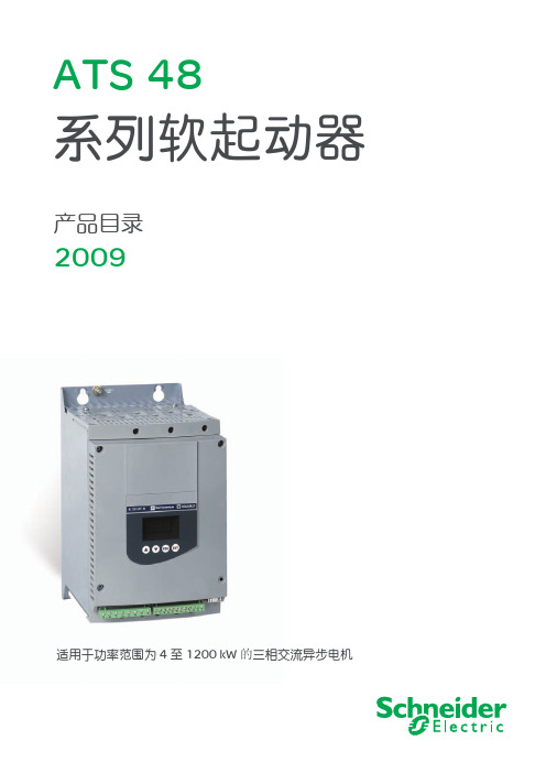
它提供带有机器和电机保护功能的软起动和减速功能,同时还具备与控制系统通讯 的功能。这些功能是设计用于离心机、泵、风机、压缩机以及输送机等应用场合, 这些机器大多数用于建筑、食品饮料及化学工业中。 ATS 48 高性能的算法对提高设 备的可用性、安全性和设置易用性起了显著作用。
ATS 48 软起动 - 软停止单元是成本效果的最佳解决方案,它可以: 通过降低机械应力、改善机械可用性来降低设备的运行成本 通过降低电机起动过程中的线路峰值电流和电压降落来降低电气配电系统的负担。 ATS 48 软起动 - 软停止单元包括 2 个系列: 3 相电压 230 至 415V, 50/60Hz 3 相电压 208 至 690V, 50/60Hz 在每个电压系列中, ATS 软起动 - 软停止单元尺寸均为标准和重载两种运行条件 设计。
默纳克me280扶梯变频器使用说明书

1.请勿带电对设备进行维修及保养。否则 有触电危险! 2.确认在变频器charge灯熄灭后才能对变 频器实施保养及维修。否则电容上残余电荷 对人造成伤害! 3.没有经过专业培训的人员请勿对变频器 实施维修及保养。否则造成人身伤害或设备 损坏!
1.2 注意事项
1.2.1 电机绝缘检查
5.请勿随意更改变频器厂家参数。否则可能 造成设备损害!
输入,同时 AI2 还可选择为
输 入 输 出 端 键盘电位器给定)
子
2×DO
1×AO(可选电压/电流输出,
也可通过 FM 选择为频率输
出或 DO 输出)
1×继电器输出
控制方式
V/F
模拟给定方 直线模式
式
多段速
可实现 8 段速
简易 PLC
可实现 8 段定时运行
摆频及定长 有
控制
通讯功能
自带 485 通讯口
2.变频器必须盖好盖板后才能上电。否则可 能引起触电!
-2-
第一章 安全及注意事项
注意
注意
3.变频器无须进行耐压试验,出厂时产品此 项已作过测试。否则可能引起事故! 4.所有外围配件是否按本手册所提供电路正 确接线。否则可能引起事故!
4.变频器运行中,避免有东西掉入设备中。 否则引起设备损坏! 5.不要采用接触器通断的方法来控制变频 器的启停。否则引起设备损坏!
2
前言
前言
ME280系列变频器是苏州默纳克控制技术 有限公司在成功推出ME320L的基础上,借助已 经得到市场广泛验证的ME320L功率驱动平台, 通过对市场的调研,针对广泛的通用客户的需 求,开发出的专门应用于扶梯驱动的变频器。 ME系列变频器全系列独立风道和散热器柜内柜 外安装可选,可以提供接近IP54防护要求的解决 方案;完善的用户密码保护,直接输入的直流母
FF450R12ME4
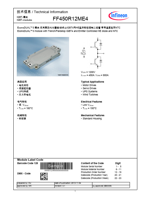
ContentoftheCode ModuleSerialNumber ModuleMaterialNumber ProductionOrderNumber Datecode(ProductionYear) Datecode(ProductionWeek)
Digit 1-5 6-11 12-19 20-21 22-23
RthCH
0,045
K/W
Tvj op -40
150 °C
负温度系数热敏电阻/NTC-Thermistor
特征值/CharacteristicValues
额定电阻值 Ratedresistance
TC = 25°C
R100偏差 DeviationofR100
TC = 100°C, R100 = 493 Ω
每个IGBT/perIGBT
每个IGBT/perIGBT λPaste=1W/(m·K)/λgrease=1W/(m·K)
IGES td on
tr td off
tf
Eon Eoff ISC RthJC RthCH Tvj op
400 nA
0,19
µs
IC = 450 A, VCE = 600 V, LS = 35 nH
Tvj = 25°C
VGE = ±15 V, di/dt = 7000 A/µs (Tvj = 150°C) Tvj = 125°C
RGon = 1,3 Ω
Tvj = 150°C
IC = 450 A, VCE = 600 V, LS = 35 nH
IC = 450 A, VGE = 15 V IC = 450 A, VGE = 15 V IC = 450 A, VGE = 15 V
开利DBFP吊顶式空气处理机组
235
1
50
2.2-4 2.61
212
2
100
3
150
4
3.0-4 3.51
200
226
DBFP100 5 10000 1970×1413×595
2/1 250 56.1 2.68 53.9 110.9 2.65 51.7 128.3* 5.58 138.7 130.8 3.13 41.6
6
300
7
5000 1752×986×500
2/2
29.0 1.39 44.0 57.0 1.36 42.8 64.1 3.07 81.7 65.7 1.57 20.8
DBFP050I
0.80-4 2.22
375
127
DBFP060
0.55-4 1.52
230
134
6000 2044×986×500
2/2
34.7 1.66 57.4 68.0 1.63 55.8 78.1 3.74 104.0 79.3 1.90 25.9
DBFP040
0.45-4 1.46
220
108
4000 1458×986×500
2/2
22.1 1.05 28.3 44.9 1.07 29.3 53.4 2.56 86.8 53.5 1.28 21.1
DBFP040I
0.55-4 1.52
300
112
DBFP050
0.55-4 1.52
290
123
组型号请务必参考选项参数)
HF : 热盘管+G3初效过滤器 WF : 湿膜+G3初效过滤器(仅适用于DBFP(X)010~060机组)
伦茨-SMV变频器操作手册
4.1 本地键盘和显示.......................................................................................19 4.2 驱动器显示和运转模式.............................................................................21 4.3 参数设置..................................................................................................22 4.4 电子编程模块 (EPM)................................................................................22 4.5 参数菜单..................................................................................................23 4.5.1 基本设置参数..................................................................................23 4.5.2 I/O 设置参数....................................................................................27 4.5.3 高级设置参数..................................................................................31 4.5.4 PID 参数.........................................................................................35 4.5.5 矢量参数..........................................................................................37 4.5.6 网络参数..........................................................................................38 4.5.7 诊断参数..........................................................................................39 4.5.8 内置通讯参数 15-30HP(11.0-22.0kW)............................................40
西门子 Sync200通用控制器 说明书
较大的塑料件附有材料标记,符合 ISO / DIS 11 469 标准,以利于环境兼容处理。
额定电压 安全超低压电路 (SELV) / 保护超低压电路 (PELV) 对外部安全绝缘变压器的要求
频率 功率
RLU2护
数量 传感器
无源
有源 信号源
Universal controllers RLU2...
CE1N3101en 07.01.2004
订货 设备组合 产品文件
技术设计
机械设计 操作、显示和连接元件
订货时,请说明控制器的名称和型号参数等信息,如 通用控制器 RLU236. "附件"中列出的产品必须单独订货。
对于设备组合,可查阅基本文件 P3101 或包含可选定的应用程序的文件。
各型号的控制器提供 39 个预置的应用功能。当调试一台设备时,必须输入相关的设备型 号。然后所有的相关功能、端子分配、设置和显示都会被激活,同时,不需要的参数也 会无效。 此外,各个型号的通用控制器都载入 2 个空应用程序:
• 1 个用于基本型 A (通风控制器) • 1 个用于基本型 U (通用控制器) 使用内置操作或维护工具 OCI700.1,控制器就可以: • 激活预置应用程序(参见"预置标准应用程序") • 修改预置应用程序 • 自由地组态应用程序 • 优化控制器地设置 有关各功能的操作, 可查阅基本文件
通用输入: • 不同测量值的无源或有源模拟输入信号 (°C, %, ---) • 数字输入信号(无电压干节点)
CE1N3101en 07.01.2004
Siemens Building Technologies HVAC Products
控制和监控功能
型号概要 附件
施耐德Zelio Control系列控制继电器产品目录 RM17 35
RM17 TG00
V
交流 208...480
V
交流 183...528
- 12 %, + 10 %
Hz
50/60 Hz±10 %
无
VA
交流 1.8
ms
60
抵抗力NF EN 61000-6-2 / IEC 61000-6-2 排放NF EN 61000-6-4 NF EN 61000-6-3 IEC 61000-6-4 IEC 61000-6-3
L1
L2
L3
24
21
22
R1
R2
12
11
14
介绍、说明: 6页
操作: 7页
特性: 8页
9
介绍、 说明
RM17 Tp00
操作: 11到14页
10
特性: 15和16页
Zelio Control 模块式测量和控制继电器
多功能三相电源控制继电器RM17 Tp00
介绍
RM17 TT、RM17 TA、RM17 TU和RM17 TE多功能继电器监测如下三相电源:
-机房温度
-机房温度 -缺相和相序
电源:50或60 Hz 高阈值:- 2...+10 Hz 低阈值:- 10...+ 2 Hz 1C/O触点 + 1个C/O触点
35 mm RM35 HZ21FM
66到69
脉冲之间的时间控制: 0.05...0.5 s, 0.1... 1s, 0.5... 5s, 1...10 s 0.1... 1min, 0.5...5 min,1...10 min 1个C/O触点
-过压或欠压
集成电流互感器 -过流
- -过流或欠流