SAE J2057-2-2001 Class A Multiplexing Actuators
法兰标准SAE_Flanges

68
V C
4 BOLT FLANGE FITTINGS
Figure 1
Refer to page 68 for metric mounting options
Figure 2
O’Ring Part No. Fig. 1
Flat Face Part No. Fig. .2
Pipe Size
Pad Size
5
/16-18x1.25 /8-16x1.25 /8-16x1.25
2.56 1.875 2.75 2.062 3.12 2.312 3.69 2.750 4.00 3.062 4.50 3.500 5.31 4.188 6.00 4.750
1.531 1.265 .245 1.781 1.515 .295 2.031 1.720 .295 2.406 2.000 .295 2.844 2.470 .355 3.344 2.950 .355 4.031 3.580 .355 4.531 4.030 .422
3
3 7
/16-14x1.50 /2-13x1.50 /2-13x1.50 /2-13x1.75 /8-11x2.00 /8-11x2.00
1 1 1 5 5
Part No. 12SFX-0 16SFX-0 20SFX-0 24SFX-0
See below for metric mounting options
K ±.010 .406 .469 .531 .656 .781
Mounting Hardware O’Ring HHCS 214 219 222 225 228
3
/8-16x1.50
3.19 2.250 3.75 2.625 4.44 3.125 5.25 3.812
世伟洛克卡套接头手册
VCO® 和 VCR® 面密封接头
见世伟洛克 VCR 金属垫片面密封 接头和 VCO O 型 圈面密封接头目 录 (MS-01-24C4), P 130 和 (MS-01-28C4), P 150。
世伟洛克卡套管接头的优点
可检测卡套管接头和转换接头 7
卡套管接头
“在 10 000 多个接头中, 没有一个泄漏。”
卡套管接头
特点
■ 活动负载和双卡套设计。 ■ 易于安装。 ■ 安装时不会把扭矩传输到卡套管上。 ■ 世伟洛克® (Swagelok®) 间隙检测规确保了首次安装的充分紧固。
可检测卡套管接头和转换接头 3
卡套管
后卡套 铰链点
螺母 前卡套
接头本体
在装配具有先进几何形状设计特点的管接头时(如上图所 示), 前卡套被推入到接头本体和卡套管形成主密封, 而后卡 套向内产生铰链作用以对卡套管形成强有力的抓紧。后卡 套的几何形状有助于产生先进的工程铰链-夹箍作用, 这种 作用可把轴向运动转化为卡套管上的径向挤压作用, 操作时 只需要很小的装配扭矩。
可定位支管, SAE/MS 直螺纹 (TTS) 和可定位支管, ISO/BSP 平行螺纹 (TTR), 39
与世伟洛克卡套管 接头对接的 Kwik 夹具式法兰, 42
卡套管转换接头
卡套管转换接头信息, 43
外螺纹
NPT 和 ISO/BSP 锥形螺纹 (RT), 44
ISO/BSP 平行螺纹 (RS 和 RP), 45
世伟洛克根据 ASTM B117-95 标准进行 了有关测试, 以评估世伟洛克卡套管接头 的耐蚀性。
若需了解有关耐蚀性测试报告的更详细 信息, 请与您授权的世伟洛克代表联系。
混用/互换
这种做法可能存在危险。可以承受高压, 振动, 真空和温度变化的无泄漏密封需 要依赖于紧公差以及始终如一的, 严格 的质量控制和良好的设计原理。精密部 件的相互作用对于可靠性和安全性是至 关重要的。
SAE_J518 Flanges介绍
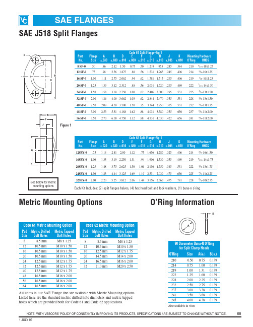
NOTE: WITH VESCORS' POLICY OF CONSTANTLY IMPROVING ITS PRODUCTS, SPECIFICATIONS ARE SUBJECT TO CHANGE WITHOUT NOTICE.681 JULY03SAE FLANGES48 SF-0 3.00 2.53 5.31 4.188 1.62.88 4.031 3.580.355.6562375/8-11x2.0056 SF-03.502.706.00 4.7501.12.884.531 4.030.422.6562415/8-11x2.00Code 62 Split Flange–Fig.1PartFlange A B D E F G H J K Mounting Hardware No.Size ±.030±.030±.010±.030±.016±.010±.010±.005±.010O’Ring HHCS 12SFX-0.75 1.14 2.812.001.12.75 1.656 1.280.325.4062143/8-16x1.5016SFX-0 1.00 1.33 3.19 2.250 1.31.94 1.906 1.530.355.4692197/16-14x1.7520SFX-0 1.25 1.48 3.75 2.625 1.50 1.06 2.156 1.750.385.5312221/2-13x1.7524SFX-01.50 1.83 4.44 3.125 1.69 1.192.531 2.030.475.6562255/8-11x2.2532SFX-02.002.205.25 3.8122.061.44 3.1562.660.475.7812283/4-10x2.75Code 61 Metric Mounting OptionPad Metric DrilledMetric Tapped Size Bolt Holes Bolt Holes 88.5 mm M8 x 1.251210.5 mm M10 x 1.501610.5 mm M10 x 1.502010.5 mm M10 x 1.502412.5 mm M12 x 1.753212.5 mm M12 x 1.754012.5 mm M12 x 1.754816.5 mm M16 x 2.005616.5 mm M16 x 2.006416.5 mmM16 x 2.00Code 62 Metric Mounting OptionPad Metric Drilled Metric Tapped Size Bolt Holes Bolt Holes 88.5 mm M8 x 1.251210.5 mm M10 x 1.501612.5 mm M12 x 1.752014.5 mm M14 x 2.002416.5 mm M16 x 2.003221.0 mmM20 x 2.5090 Durometer Buna-N O’Ring for Split Clamp Heads O’Ring Size A (in.)B (in.)2100.500.750.1392140.75 1.000.139219 1.00 1.310.139222 1.25 1.600.139228 2.00 2.250.139232 2.50 2.750.139237 3.00 3.380.139241 3.50 3.880.1392454.004.380.139Also available in vitonAll items in our SAE Flange line are available with Metric Mounting options.Listed here are the standard metric drilled hole diameters and metric tapped holes which are provided both for Code 61 and Code 62 applications.Metric Mounting OptionsEach Kit Includes: (2) split flanges halves, (4) hex head bolt and lock washers, (1) buna-n o’ringNOTE: WITH VESCORS' POLICY OF CONSTANTLY IMPROVING ITS PRODUCTS, SPECIFICATIONS ARE SUBJECT TO CHANGE WITHOUT NOTICE.691 JULY 03Part Numbers with “U” Suffix include Bolt Kit and O’RingPart Numbers with “U” Suffix include Bolt Kit and O’RingPart Numbers with “U” Suffix include Bolt Kit and O-RingO’Ring Flat Face Pipe Pad G K K Mounting HardwarePart No.Part No.Size SizeA B C D E FThread HI J Drill TapFig. 1Fig. .2NPTFDia.UN-2B O’Ring SHCSCODE 61 3000 PSI NPTF THREADW43-8-8-U W104-8-8.50.50 1.81 2.13.688 1.500 1.42.63.50.50 1.25 1.000.3445/16-182105/16-18x1.25W43-12-12-U W104-12-12.75.75 1.97 2.56.875 1.875 1.42.71.75.75 1.54 1.250.4063/8-162143/8-16x1.50W43-16-16-U W104-16-16 1.00 1.00 2.17 2.75 1.031 2.062 1.50.711.00 1.00 1.81 1.560.4063/8-162193/8-16x1.50W43-20-20-U W104-20-20 1.25 1.25 2.68 3.12 1.188 2.312 1.61.83 1.25 1.25 2.22 1.750.4697/16-142227/16-14x1.75W43-24-24-U W104-24-24 1.50 1.50 3.07 3.66 1.406 2.750 1.77.98 1.50 1.50 2.50 2.115.5311/2-132251/2-13x1.75W43-32-32-U W104-32-32 2.00 2.00 3.54 4.00 1.688 3.062 1.77.98 2.00 2.00 3.12 2.490.5311/2-132281/2-13x1.75W43-40-40-U W104-40-40 2.50 2.50 4.09 4.49 2.000 3.500 1.97.98 2.50 2.50 3.62 2.995.5311/2-132321/2-13x1.75W43-48-48-U W104-48-483.003.004.885.282.438 4.1881.97 1.063.003.004.473.615.6565/8-112375/8-11x2.00O’RingFlat Face Pipe Pad G K K Mounting Hardware Part No.Part No.Size SizeA B C D E FStraight H I JDrill TapFig. 1Fig. .2ThreadDia.UN-2B O’Ring SHCSCODE 61 3000 PSI SAE STRAIGHT THREADW46-12-12-U –.75.75 1.97 2.56.875 1.875 1.42.7111/16-12.75 1.54 1.250.406–2143/8-16x1.50W46-16-16-U – 1.00 1.00 2.17 2.75 1.031 2.062 1.50.7115/16-12 1.00 1.81 1.560.406–2193/8-16x1.50W46-20-20-U – 1.25 1.25 2.68 3.12 1.188 2.312 1.61.8315/8-12 1.25 2.22 1.750.469–2227/16-14x1.75W46-24-24-U–1.501.503.073.661.4062.7501.77.9817/8-121.502.502.115.531–2251/2-13x1.75O’RingFlat Face Pipe Pad G K K Mounting Hardware Part No.Part No.Size SizeA B C D E FThread H I JDrill TapFig. 1Fig. .2NPTFDia.UN-2B O’Ring SHCSCODE 61 3000 PSI NPTF THREAD REDUCINGW43-12-16-U –.75 1.00 2.17 2.75 1.031 2.062 1.50.71.75.750 1.81 1.560.406–2193/8-16x1.50W43-16-20-U – 1.00 1.25 2.68 3.12 1.188 2.312 1.61.83 1.00 1.00 2.22 1.750.469–2227/16-14x1.75W43-20-24-U – 1.25 1.50 3.07 3.66 1.406 2.750 1.77.98 1.25 1.25 2.50 2.115.531–2251/2-13x1.75W43-24-32-U–1.502.003.544.001.688 3.062 1.77.981.501.503.122.490.531–2281/2-13x1.754 BOLT FLANGE FITTINGSNOTE: WITH VESCORS' POLICY OF CONSTANTLY IMPROVING ITS PRODUCTS, SPECIFICATIONS ARE SUBJECT TO CHANGE WITHOUT NOTICE.701 JULY 03Part Numbers with “U” Suffix include Bolt Kit and O’RingO’RingFlat Face PipePad G K K Mounting Hardware Part No.Part No.Size SizeA B C D E FThread H I JDrill TapFig. 1Fig. .2NPTFDia.UN-2B O’Ring SHCSCODE 626000 PSI NPTF THREADW44-8-8-UW45-8-8.50.50 1.81 2.21.718 1.594 1.25.63.500.50 1.33 1.000.3445/16-182105/16-18x1.25W44-12-12-U W45-12-12.75.75 2.17 2.80.937 2.000 1.25.83.750.75 1.65 1.250.4063/8-162143/8-16x1.50W44-16-16-U W45-16-16 1.00 1.00 2.56 3.19 1.093 2.250 1.50.98 1.000 1.00 1.98 1.560.4927/16-142197/16-14x1.75W44-20-20-U W45-20-20 1.25 1.25 3.07 3.75 1.250 2.625 1.50 1.06.1.250 1.25 2.36 1.750.5311/2-132221/2-13x1.75W44-24-24-U W45-24-24 1.50 1.50 3.70 4.41 1.437 3.125 1.75 1.18 1.500 1.50 2.68 2.115.6565/8-112255/8-11x2.25W44-32-32-U W45-32-322.002.004.505.281.750 3.8121.75 1.46.2.0002.003.382.490.7813/4-102283/4-10x2.75O’Ring Flat Face Pipe Pad GK K Mounting Hardware Part No.Part No.SizeSizeA B C D E FStraight H I JDrill TapFig. 3Fig. .4ThreadDia.UN-2B O’Ring SHCSCODE 626000 PSI SAE STRAIGHT THREADW48-12-12-U W49-12-12.75.75 2.17 2.80.937 2.000 1.25.8311/16-12.751.65 1.250.4063/8-162143/8-16x1.50W48-16-16-U W49-16-16 1.00 1.00 2.56 3.19 1.093 2.250 1.50.9815/16-12 1.00 1.98 1.560.4927/16-142197/16-14x1.75W48-20-20-U W49-20-20 1.25 1.25 3.07 3.75 1.250 2.625 1.50 1.0615/8-12 1.25 2.36 1.750.5311/2-132221/2-13x1.75W48-24-24-U W49-24-24 1.50 1.50 3.70 4.41 1.437 3.125 1.75 1.1817/8-12 1.50 2.68 2.1155.6565/8-11225 5/8-11x2.25W48-32-32-U W49-32-322.002.004.505.281.750 3.8121.75 1.4621/2-122.003.382.490.7813/4-102283/4-10x2.754 BOLT FLANGE FITTINGSPart Numbers with “U” Suffix include Bolt Kit and O’RingNOTE: WITH VESCORS' POLICY OF CONSTANTLY IMPROVING ITS PRODUCTS, SPECIFICATIONS ARE SUBJECT TO CHANGE WITHOUT NOTICE.711 JULY 03Part Numbers with “U” Suffix include Bolt Kit and O’RingPart Numbers with “U” Suffix include Bolt Kit and O’RingPart Numbers with “U” Suffix include Bolt Kit and O’RingO’RingFlat Face Pipe Pad J J KK Mounting Hardware Part No.Part No.Size SizeA B C D E F G HMin.Max.Drill Tap Fig.1Fig. 2Dia.UN-2B O’Ring SHCS500 PSI FLAT SOCKET-PIPEW72-48-48-U – 3.00 3.00 5.12 5.31 2.438 4.188 1.38 1.12 3.547 3.00 3.615 3.625.656–2375/8-11x2.50W72-56-56-U – 3.50 3.50 5.50 6.00 2.750 4.750 1.44 1.19 4.047 3.50 4.095 4.115.656–241 5/8-11x2.75W72-64-64-U–4.004.006.00 6.383.062 5.125 1.501.254.5784.00 4.595 4.615.656–2455/8-11x2.75O’RingFlat Face PipePad G H J J K K Mounting Hardware Part No.Part No.Size SizeA B C D E FDia.Dia.Dia.DIA.Drill Tap Fig.1Fig. 2Min.Max.Dia.UN-2B O’Ring SHCSCODE 61 3000 PSI FLAT SOCKET-PIPEW4-8-8-U W61-8-8.50.50 1.813 2.125.688 1.500.75.560.855.50 1.000 1.005.3445/16-182105/16-18x1.50W4-12-12-U W61-12-12.75.75 2.063 2.563.875 1.875.75.560 1.062.75 1.250 1.255.4063/8-162143/8-16x1.50W4-16-16-U W61-16-16 1.00 1.00 2.313 2.750 1.031 2.063.88.630 1.326 1.00 1.560 1.565.4063/8-162193/8-16x1.75W4-20-20-U W61-20-20 1.25 1.25 2.875 3.125 1.188 2.313.94.690 1.672 1.25 1.750 1.755.4697/16-142227/16-14x1.75W4-24-24-U W61-24-24 1.50 1.50 3.250 3.688 1.406 2.750 1.19.750 1.922 1.50 2.115 2.125.5311/2-132251/2-13x2.25W4-32-32-U W61-32-32 2.00 2.00 3.813 4.000 1.688 3.063 1.38.875 2.406 2.00 2.490 2.500.5311/2-132281/2-13x2.50W4-40-40-U W61-40-40 2.50 2.50 4.281 4.500 2.000 3.500 1.75 1.00 2.906 2.50 2.995 3.005.5311/2-132321/2-13x2.75W4-48-48-UW61-48-483.003.00 5.156 5.313 2.4384.188 2.121.253.5473.00 3.615 3.625.6565/8-112375/8-11x3.50O’Ring Flat Face Pipe Pad J JKK Mounting Hardware Part No.Part No.Size SizeA B C D E FG HMin.Max.DrillTap Fig.1Fig. 2Dia.Dia.UN-2B O’Ring SHCSCODE 61 3000 PSI FLAT SOCKET-PIPE REDUCING FLANGESW4-8-12-U –.50.75 2.0632.563.875 1.875.75.560.855.75 1.250 1.255.406–2143/8-16x1.50W4-12-16-U –.75 1.00 2.3132.750 1.031 2.063.88.630 1.062 1.00 1.560.565.406–2193/8-16x1.75W4-16-20-U – 1.00 1.25 2.8753.125 1.188 2.313.94.690 1.326 1.25 1.750 1.755.469–2227/16-14x1.75W4-20-24-U – 1.25 1.50 3.2503.688 1.406 2.750 1.19.750 1.672 1.50 2.115 2.125.531–2251/2-13x2.25W4-24-32-U–1.502.003.8134.000 1.688 3.063 1.38.8751.9222.00 2.490 2.500.531–2281/2-13x2.504 BOLT FLANGE FITTINGSNOTE: WITH VESCORS' POLICY OF CONSTANTLY IMPROVING ITS PRODUCTS, SPECIFICATIONS ARE SUBJECT TO CHANGE WITHOUT NOTICE.721 JULY 03O’Ring Flat Face Pipe Pad J J KK Mounting Hardware Part No.Part No.Size SizeA B C D E FG H Min.Max.Drill Tap Fig.1Fig. 2Dia.Dia.Dia.UN-2BO’RingSHCSCODE 626000 PSI FLAT SOCKET PIPEW59-8-8-UW60-8-8.50.50 1.94 2.30.718 1.594 1.25.560.855.50 1.000 1.005.3445/16-182105/16-18x2.00W59-12-12-U W60-12-12.75.75 2.50 2.95.937 2.000 1.25.560 1.063.751.250 1.255.4063/8-162143/8-16x2.00W59-16-16-U W60-16-16 1.00 1.00 2.75 3.19 1.093 2.250 1.50.630 1.328 1.00 1.560 1.565.4697/16-142197/16-14x2.50W59-20-20-U W60-20-20 1.25 1.25 3.06 3.75 1.250 2.625 1.50.690 1.672 1.25 1.750 1.755.5311/2-132221/2-13x2.50W59-24-24-U W60-24-24 1.50 1.50 3.75 4.44 1.437 3.125 1.75.750 1.922 1.50 2.115 2.125.6565/8-112255/8-11x3.00W59-32-32-U W60-32-322.002.004.505.251.750 3.812 1.75.8752.4062.00 2.490 2.500.7813/4-102283/4-10x3.004 BOLT FLANGE FITTINGSPart Pad J J No.SizeA BC D E HDia.Dia.K Fig. 3±.010±.010Min.Max.Dia.CODE 62 O-RING SPACERASX-12-GP0.7502.50 2.950.937 2.000 1.2500.750 1.250 1.2560.406ASX-16-GP 1.000 2.753.19 1.093 2.250 1.500 1.000 1.560 1.5650.469ASX-20-GP 1.250 3.06 3.75 1.250 2.625 1.500 1.250 1.750 1.7550.531ASX-24-GP 1.500 3.754.44 1.437 3.125 1.750 1.500 2.115 2.1250.656ASX-32-GP 2.0004.505.251.750 3.8121.7502.0002.490 2.5000.781CODE 61 O-RING SPACERAS-8-GP 0.500 1.813 2.1250.688 1.5000.880.500 1.000 1.0050.344AS-12-GP 0.750 2.063 2.5630.875 1.8750.880.750 1.250 1.2550.406AS-16-GP 1.000 2.313 2.750 1.031 2.0630.88 1.000 1.560 1.5650.406AS-20-GP 1.250 2.875 3.125 1.188 2.3130.94 1.250 1.750 1.7550.469AS-24-GP 1.500 3.250 3.688 1.406 2.750 1.19 1.500 2.115 2.1250.531AS-32-GP2.0003.8134.000 1.688 3.0631.382.0002.490 2.5000.531NOTE: WITH VESCORS' POLICY OF CONSTANTLY IMPROVING ITS PRODUCTS, SPECIFICATIONS ARE SUBJECT TO CHANGE WITHOUT NOTICE.731 JULY03O’RingFlat Face PadJ J K K Mounting Hardware Part No.Part SizeA B C D EMin.Max.Drill Tap Fig. 1Fig. 2Dia.UN-2B O’Ring SHCSCODE 61 3000 PSI BLANKINGW36-8-8-U W37-8-8.50 1.813 2.125.688 1.500.750 1.000 1.005.3445/16-182105/16-18x1.50W36-12-12-U W37-12-12.75 2.063 2.563.875 1.875.7501.2501.255.4063/8-162143/8-16x1.50W36-16-16-U W37-16-16 1.002.313 2.750 1.031 2.063.880 1.560 1.565.4063/8-162193/8-16x1.75W36-20-20-U W37-20-20 1.25 2.875 3.125 1.188 2.313.940 1.7501.755.4697/16-142227/16-14x1.75W36-24-24-U W37-24-24 1.50 3.250 3.688 1.406 2.750 1.190 2.115 2.125.5311/2-132251/2-13x2.25W36-32-32-U W37-32-32 2.00 3.813 4.000 1.688 3.063 1.440 2.490 2.500.5311/2-132281/2-13x2.50W36-40-40-U W37-40-40 2.50 4.281 4.500 2.000 3.500 1.815 2.995 3.005.5311/2-132321/2-13x2.75W36-48-48-U W37-48-483.005.156 5.313 2.438 4.188 2.190 3.6153.625.6565/8-112375/8-11x3.50CODE 62 6000 PSI BLANKINGW38-8-8-U W39-8-8.50 1.94 2.30.718 1.594.870 1.0001.005.3445/16-18210 5/16-18x1.50 W38-12-12-U W39-12-12 .75 2.50 2.95.937 2.000 1.250 1.250 1.255.4063/8-162143/8-16x1.50W38-16-16-U W39-16-16 1.00 2.75 3.19 1.093 2.250 1.500 1.560 1.565.4697/16-142197/16-14x1.75W38-20-20-U W39-20-20 1.25 3.06 3.75 1.250 2.625 1.565 1.750 1.755.5311/2-132221/2-13x1.75W38-24-24-U W39-24-24 1.50 3.75 4.44 1.437 3.125 1.815 2.115 2.125.6565/8-112255/8-11x2.25W38-32-32-U W39-32-32 2.00 4.50 5.25 1.750 3.812 1.815 2.490 2.500.7813/4-102283/4-10x2.00W38-40-40-U W39-40-40 2.50 5.87 6.87 2.312 4.875 2.060 2.995 3.005.9067/8-92327/8-9x3.50W38-48-48-U W39-48-483.007.008.502.812 6.000 2.6203.6153.625 1.15611/8-7237 11/8-7x4.50Figure 1Figure 2Part Numbers with “U” Suffix include Bolt Kit and O’Ring4 BOLT FLANGE FITTINGSNOTE: WITH VESCORS' POLICY OF CONSTANTLY IMPROVING ITS PRODUCTS, SPECIFICATIONS ARE SUBJECT TO CHANGE WITHOUT NOTICE.741 JULY 03Part Numbers with ”U” Suffix include Bolt Kit and O’RingPart Numbers with “U” Suffix include Bolt Kit and O’RingFigure 1O’Ring Pad G J J K KMounting Hardware Part No.SizeA B C D EStraight HMin.Max.Drill Tap L M NFig.1ThreadDia.UN-2BO’RingsSHCSCODE 61 3000 PSI ELBOW NPTF THREADW168-12-12-U .75 1.69 2.56.875 1.875 1.25.75 .75 1.250 1.255.406– 2.28 1.44.8752143/8-16x2.00W168-16-16-U 1.00 1.94 2.75 1.031 2.062 1.50 1.00 1.00 1.560 1.565.406– 2.62 1.66 1.0622193/8-16x2.25W168-20-20-U 1.25 2.19 3.12 1.188 2.312 1.81 1.25 1.25 1.750 1.755.469– 3.00 1.91 1.1882227/16-14x2.75W168-24-24-U 1.50 2.56 3.69 1.406 2.750 2.00 1.50 1.50 2.115 2.125.531– 3.33 2.05 1.3122251/2-13x3.00W168-32-32-U2.003.064.331.688 3.0622.502.002.002.490 2.500.531–3.812.28 1.6562285/8-11x3.50CODE 61 3000 PSI ELBOW SOCKET WELDW176-12-12-U .75 1.69 2.56.8751.875 1.25 1.062.75 1.2501.255.406–2.28 1.44.8750.560.752143/8-16x2.00W176-16-16-U 1.00 1.94 2.75 1.031 2.062 1.50 1.328 1.00 1.560 1.565.406– 2.62 1.66 1.0620.56 1.002193/8-16x2.25W176-20-20-U 1.25 2.19 3.12 1.188 2.312 1.81 1.672 1.25 1.750 1.755.469– 3.00 1.91 1.1880.62 1.252227/16-14x2.75W176-24-24-U 1.50 2.56 3.69 1.406 2.750 2.00 1.922 1.50 2.115 2.125.531– 3.28 2.05 1.3120.691.502251/2-13x3.00W176-32-32-U2.003.064.33 1.688 3.062 2.50 2.406 2.00 2.4902.500.531–3.812.28 1.656.075 2.002281/2-13x3.50O’RingPad G J J K KMounting Hardware Part No.SizeA B C D E Thread H Min.Max.Drill Tap L M NFig.1NPTDia.UN-2BO’RingsSHCSCODE 61 3000 PSI ELBOW SAE STRAIGHT THREADW164-12-12-U .75 1.69 2.56.875 1.875 1.2511/16-12.75 1.250 1.255.406– 2.28 1.44.8752143/8-16x2.00W164-16-16-U 1.00 1.94 2.75 1.031 2.062 1.5015/16-12 1.00 1.560 1.565.406– 2.62 1.66 1.062219 3/8-16x2.25W164-20-20-U 1.25 2.19 3.12 1.188 2.312 1.8115/8-12 1.25 1.750 1.755.469– 3.00 1.91 1.1882227/16-16x2.75W164-24-24-U 1.50 2.56 3.69 1.406 2.750 2.0017/8-12 1.50 2.115 2.125.531– 3.33 2.05 1.312225 1/2-13x3.00W164-32-32-U2.003.064.331.688 3.0622.5021/2-122.002.490 2.500.531–3.812.28 1.6562281/2-13x3.504 BOLT FLANGE FITTINGSNOTE: WITH VESCORS' POLICY OF CONSTANTLY IMPROVING ITS PRODUCTS, SPECIFICATIONS ARE SUBJECT TO CHANGE WITHOUT NOTICE.751 JULY 03O’RingFlat Face Pipe Pad GH K K Mounting Hardware Part No.Part No.SizeSizeA B C D E FPipe Pipe JDrill Tap Fig. 1Fig. .2O.D.I.D.Dia.UN-2B O’Ring SHCSCODE 61 BUTT WELD-SCHED 40 PIPEW35-12-U W34-12 .75.75 1.97 2.56.875 1.875 1.42.71 1.050.82 1.250.4063/8-162143/8-16 x 1.50W35-16-U W34-16 1.00 1.00 2.17 2.75 1.031 2.062 1.50.71 1.315 1.04 1.560.4063/8-162193/8-16 x 1.50W35-20-U W34-20 1.25 1.25 2.68 3.12 1.188 2.312 1.61.83 1.660 1.38 1.750.4697/16-142227/16-14 x 1.75W35-24-U W34-24 1.50 1.50 3.07 3.66 1.406 2.750 1.73.98 1.900 1.61 2.115.5311/2-132251/2-13 x 1.75W35-32-U W34-32 2.00 2.00 3.54 4.00 1.688 3.062 1.77.98 2.375 2.06 2.490.5311/2-132281/2-13 x .1.75W35-40-U W34-40 2.50 2.50 4.09 4.49 2.000 3.500 1.97.98 2.875 2.46 2.995.5311/2-132321/2-13 x 1.75W35-48-U*W34-48 * 3.003.004.885.282.4384.1881.971.063.500 3.06 3.615.6565/8-112375/8-11 x 2.00O’Ring Flat Face Pipe Pad G H K K Mounting Hardware Part No.Part No.Size SizeA B C D E F Pipe Pipe JDrill Tap Fig. 1Fig. .2O.D.I.D.Dia.UN-2B O’Ring SHCSCODE 61 BUTT WELD-SCHED 80 PIPEW24-12-U W23-12 .75.75 1.97 2.56.875 1.875 1.42.71 1.050.742 1.250.4063/8-162143/8-16 x 1.50W24-16-U W23-16 1.00 1.00 2.17 2.75 1.031 2.062 1.50.71 1.315.957 1.560.4063/8-162193/8-16 x 1.50W24-20-U W23-20 1.25 1.25 2.68 3.12 1.188 2.312 1.61.83 1.660 1.278 1.750.4697/16-142227/16-14 x 1.75W24-24-U W23-24 1.50 1.50 3.07 3.66 1.406 2.750 1.73.98 1.900 1.500 2.1155311/2-132251/2-13 x 1.75W24-32-U W23-32 2.00 2.00 3.54 4.00 1.688 3.062 1.77.98 2.375 1.939 2.490.5311/2-132281/2-13 x 1.75W24-40-U W23-40 2.50 2.50 4.09 4.49 2.000 3.500 1.97.98 2.875 2.323 2.995.5311/2-132321/2-13 x 1.75W24-48-U*W23-48 * 3.003.004.885.282.4384.1881.971.063.500 2.900 3.615.6565/8-112375/8-11 x 2.00O’RingFlat Face Pipe Pad G H K K Mounting Hardware Part No.Part No.Size SizeA B C D E F Pipe Pipe JDrill Tap Fig. 1Fig. .2O.D.I.D.Dia.UN-2B O’Ring SHCSCODE 61 BUTT WELD-SCHED 160 PIPEW27-12-U W25-12 .75.75 1.97 2.56.875 1.875 1.42.71 1.050.614 1.250.4063/8-162143/8-16 x 1.50W27-16-U W25-16 1.00 1.00 2.17 2.75 1.031 2.062 1.50.71 1.315.815 1.560.4063/8-162193/8-16 x 1.50W27-20-U W25-20 1.25 1.25 2.68 3.12 1.188 2.312 1.61.83 1.660 1.160 1.750.4697/16-142227/16-14 x 1.75W27-24-U W25-24 1.50 1.50 3.07 3.66 1.406 2.750 1.73.98 1.900 1.337 2.115.5311/2-132251/2-13 x 1.75W27-32-U W25-32 2.00 2.00 3.54 4.00 1.688 3.062 1.77.98 2.375 1.689 2.490.5311/2-132281/2-13 x 1.75W27-40-U W25-40 2.50 2.50 4.09 4.49 2.000 3.500 1.97.98 2.875 2.125 2.995.5311/2-132321/2-13 x 1.75W27-48-U*W25-48 *3.003.004.885.282.4384.1881.971.063.5002.6243.615.6565/8-112375/8-11 x 2.004 BOLT FLANGE FITTINGS*note-bar stock material Part Numbers with ”U” Suffix include Bolt Kit and O’RingNOTE: WITH VESCORS' POLICY OF CONSTANTLY IMPROVING ITS PRODUCTS, SPECIFICATIONS ARE SUBJECT TO CHANGE WITHOUT NOTICE.761 JULY 034 BOLT FLANGE FITTINGSCODE 62 BUTT WELD-SCHED 80 PIPEW28-12-U –.75.75 2.17 2.80.937 2.000 1.390.83 1.0500.742 1.2500.4063/8-162143/8-16 x 1.50W28-16-U – 1.00 1.00 2.56 3.19 1.093 2.250 1.610.83 1.3150.957 1.5600.4697/16-142197/6-14 x 1.75W28-20-U – 1.25 1.25 3.07 3.75 1.250 2.625 1.730.98 1.660 1.278 1.7500.5311/2-132221/2-13 x 1.75W28-24-U – 1.50 1.50 3.70 4.41 1.437 3.125 2.17 1.18 1.900 1.500 2.1150.6565/8-112255/8-11 x 2.25W28-32-U – 2.00 2.00 4.50 5.28 1.750 3.812 2.56 1.45 2.375 1.939 2.4900.7813/4-102283/4-10 x 2.75W28-40-U*– 2.50 2.50 5.00 6.88 2.312 4.875 2.37 1.50 2.875 2.323 2.9950.9407/8-92327/8-9 x 3.00W28-48-U*– 3.003.006.008.502.8126.0002.962.003.500 2.900 3.6151.19011/8-723711/8-7 x 4.00O’Ring Flat Face Pipe Pad G H K K Mounting Hardware Part No.Part No.Size SizeA B C D E F Pipe Pipe JDrill Tap Fig. 1Fig. .2O.D.I.D.Dia.UN-2B O’Ring SHCSCODE 62 BUTT WELD-SCHED 160 PIPE–W29-120.750.75 2.17 2.800.937 2.000 1.380.83 1.0500.614 1.250.4063/8-162143/8-16 x 1.50–W29-16 1.00 1.00 2.56 3.19 1.093 2.250 1.610.83 1.3150.815 1.560.4697/16-142197/16-14 x 1.75–W29-20 1.25 1.25 3.07 3.75 1.250 2.625 1.730.98 1.660 1.160 1.750.5311/2-132221/2-13 x 1.75–W29-24 1.50 1.50 3.70 4.41 1.437 3.125 2.17 1.18 1.900 1.337 2.115.6565/8-112255/8-11 x 2.25–W29-32 2.00 2.00 4.50 5.28 1.750 3.812 2.56 1.46 2.375 1.689 2.490.7813/4-102283/4-10 x 2.75–W29-40* 2.50 2.50 5.00 6.88 2.312 4.875 2.37 1.50 2.875 2.125 2.995.9407/8-92327/8-9 x 3.00–W29-48*3.003.006.008.502.8126.0002.962.003.5002.6243.6151.19011/8-723711/8-7 x 4.00PartPad K No.SizeA B C D E F G H JTap Fig. 1UNC-2BCODE 61 3000 PSI TANK PILOTW22-12.75 1.69 2.56.875 1.875 1.18.62 1.375.75 1.063/8-16W22-16 1.00 1.94 2.75 1.031 2.062 1.25.56 1.500 1.00 1.123/8-16W22-20 1.25 2.19 3.12 1.188 2.312 1.44.62 1.750 1.25 1.207/16-14W22-24 1.50 2.56 3.69 1.406 2.750 1.75.81 2.125 1.50 1.621/2-13W22-32 2.00 3.06 4.00 1.688 3.062 2.00 1.06 2.500 2.00 1.881/2-13W22-402.503.564.502.0003.5002.311.123.2502.50 2.191/2-13*note-bar stock materialPart Numbers with ”U” Suffix include Bolt Kit and O’Ring。
ARO Ergo Line系列焊钳中文说明书

T264 CN
1
ARO 1, avenue de Tours - 72500 CHATEAU-DU-LOIR - FRANCE - TEL. +33 (0)2 43 44 74 00
1. 说明
在所有型号的产品中,定臂与焊钳的其它部分绝缘,而活动臂和焊钳的其它部 分都接地。
在初级绕组方面,后罩起电气盒的作用,在该后罩上直接固定了一个辅助信号 分配器和电源插座。
XLA – XMA – XPA – XWA CLA – CMA – CWA 手动焊钳
技术说明书
T264 CN
更改说明
日期
09 / 00
文件编号
T264F
更改性质
创建
ARO 1, avenue de Tours - 72500 Château du Loir – 法国 电话:33 (0)2 43 44 74 00 – 电传:720 008 AROMACC – 传真:33 (0)2 43 44 74 01.
密封圈和滑块鼻子导轨的更换
60
5.10.
“C”型焊钳定臂的更换
61
5.11.
“X”型焊钳挂钩的更换
61
5.12.
“X”型焊钳轴心活动钳臂和铰链绝缘件的更换
62
5.13.
“X”型焊钳定臂的更换
62
5.14.
“X”型焊钳行程的调节
62
5.15.
作动筒的更换
63
5.16.
密封、作动筒和汽缸密封圈的更换
63
它应与一个电子控制箱一起工作,该控制箱中包括: - 含有切断阀、过滤和压力选择的流体(空气、水)控制盘, - 一个可编制的焊接程序, - 一个功率单位(闸晶管板), - 一个差动断路器。
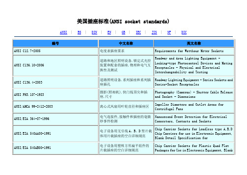
美国插标准
电连接器和插座的电容试验程序
Capacitance Test Procedure for Electrical Connectors and Sockets
ANSI/EIA-364-52A-2003
连接器/插座中使用的触点终端的软钎焊性的TP52试验程序
TP 52 Test Procedures for Solderability of Contact Terminations Use in Connectors/Sockets
ANSI/EIA-540A000-A-1990
ANSI/EIA 540AA00-1991
电子设备用无引线A、B、D型片载体用片载插座的空白详细规范
Chip Carrier Sockets for Leadless type A,B,D Chip Carriers for use in Electronic Equipment, Blank Detail Specification for
Combustion Characteristics Test Procedure for Electrical Connector Housing, Connector Assemblies and Sockets
ANSI/EIA-364-82A-2005
电连接器套、连接器组件和插座的塑料腐蚀性试验程序
Roadway and Area Lighting Equipment - Locking-type Photocontrol Devices and Mating Receptacles - Physical and Electrical Interchangeability and Testing
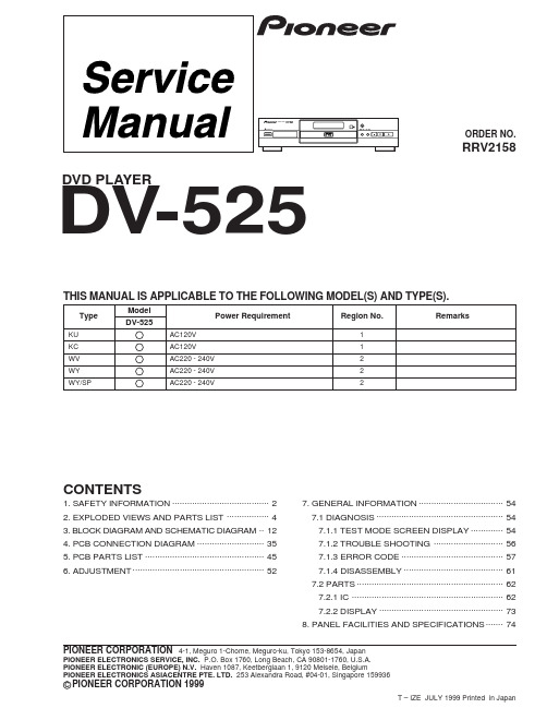
先锋高保真DVD机dv-525电路图纸维修手册
Device under test
Reading should
Leakage current
not be above 0.5mA
tester
Test all exposed metal surfaces
Also test with plug reversed (Using AC adapter plug as required)
Earth ground
ANY MEASUREMENTS NOT WITHIN THE LIMITS OUTLINED ABOVE ARE INDICATIVE OF A POTENTIAL SHOCK HAZARD AND MUST BE CORRECTED BEFORE RETURNING THE APPLIANCE TO THE CUSTOMER.
Region No.
Remarks
KU
AC120V
1
KC
AC120V
1
WV
AC220 - 240V
2
WY
AC220 - 240V
2
WY/SP
AC220 - 240V
2
CONTENTS
1. SAFETY INFORMATION ....................................... 2 2. EXPLODED VIEWS AND PARTS LIST ................. 4 3. BLOCK DIAGRAM AND SCHEMATIC DIAGRAM .. 12 4. PCB CONNECTION DIAGRAM ........................... 35 5. PCB PARTS LIST ................................................ 45 6. ADJUSTMENT ..................................................... 52
MS4120F、MS4620F、MS8120F、S2024-F和S20230-F快速作用双位置驱动器
PRODUCT DATAPut Bar Code Here63-2584-10MS4120F; MS4620F; MS8120F; S2024-F; S20230-F Fast-Acting, Two-Position ActuatorsAPPLICATIONThe MS4120F , MS4620F , MS8120F , S2024-F , and S20230-F Fast-Acting, T wo-Position Actuators are spring return direct coupled actuators (DCA) for on/off damper control. The actuator accepts an on/off signal from a single-pole, single-throw (spst) controller. Reversible mounting allows actuator to be used for either clockwise (cw) or counterclockwise (ccw) spring rotation.Designed to operate reliably in smoke control systemsrequiring Underwriter’s Laboratories Inc. UL555S ratings up to 350°F .APPLICABLE LITERATURE—Specification Data Sheet63-2592—Motor/Actuator Selection Guide for Damper Applications63-8419—Engineering Manual of Automatic Control (also called The Gray Manual)77-1100—Direct Coupled Actuator Quick Selection Guide 63-8553—Damper T orque Calculator63-8437FEATURES•175 lb-in. (20 Nm) minimum driving torque at 350°F (176°C).•Reversible mounting facilitates use in either clockwise (cw) or counterclockwise (ccw) spring rotation.•Integral spring return ensures level of return torque.•Stainless steel internal spring.•Fifteen-second spring return timing.•No special cycling required during long-term holding. (See Operation section.)•No audible noise during holding.•Patent pending design eliminates need for limit switches to reduce power consumption.•Models available for 24, 120, and 230 Vac applications.•Ninety-five degree angle of rotation.•Actuator holds rated torque at reduced power level.•Die-cast aluminum housing.•Housing design allows flush mounting to damper.•Self-centering shaft adapter (SCSA), patent pending.•Designed to operate reliably in smoke control systems requiring Underwriter’s Laboratories Inc. UL555S ratings up to 350°F.MS4120F, MS4620F, MS8120F•High temperature Teflon ® lead wires.•Models available with integral high temperature (350°F) SPST position-indicating switches (7°, 85° stroke).S2024-F, S20230-F•Double-insulation rating.•High-temperature, halogen-free, silicone-free leadwires.•Models available with integral high temperature (350°F)SPDT position-indicating switches (7°, 85° stroke).MS4120F; MS4620F; MS8120F; S2024-F; S20230-F FAST-ACTING, TWO-POSITION ACTUATORS63-2584—102SPECIFICATIONSModels: See Tables 1, 2, and 3.Table 1. Models.aInternal switches are designed to pass UL555Srequirements (at 350°F).Dimensions: See Fig. 1.Device Weight:MS4120F , MS4620F , S20230-F: 7.5 lb (3.4 kg)MS8120F , S2024-F: 6.25 lb (2.8 kg)Stroke: 95° ± 3°, mechanically limited.Electrical Ratings:Power Input:MS4120F: 120 Vac ±10%, 60 Hz.MS4620F ,S; S20230-F: 230 Vac ±10%, 50/60 Hz.MS8120F ,S; S2024-F: 24 Vac +20%, -10%, 50/60 Hz (Class 2).Power Consumption:MS4120F: Driving: 0.35A, 35W. Holding: 0.15A, 10W.MS4620F ,S; S20230-F:Driving: 0.20A, 35W. Holding: 0.14A, 10W.MS8120F ,S; S2024-F: Driving: 45 VA. Holding: 10 VA.Electrical Connections:Lead Wires:MS4120F , MS4620F , MS8120F: 1m T eflon wire.MS4620S, MS8120S, S2024-F , S20230-F: 1m halogen-free, silicone-free wire.T wo integral 3/8 in. flexible conduit connections.Timing (At Rated Torque and Voltage):Drive Open: 15 seconds typical.Spring Close: 15 seconds typical.Auxiliary Switches:Dry ContactRatings (maximum load): 250 Vac, 5A resistive.Settings (fixed): 7° nominal stroke, 85° nominal stroke.Torque Rating (at Rated Voltage):T ypical Holding (minimum at 350°F): 175 lb-in. (20 Nm).Spring Return (minimum at 350°F): 175 lb-in. (20 Nm).Stall Maximum (fully open at 75°F): 425 lb-in. (48.0 Nm).350°F Minimum Driving: 175 lb-in. (20 Nm).Design Life (at Rated Voltage): 30,000 full stroke cycles.Minimum Damper Shaft Length:1 in. (25 mm); 3-1/4 (83 mm) recommended.Cycling Requirements:Prolonged holding-period (1 year) testing of these actuators has been performed with no spring return failures. The actuator and the internal spring are designed to require no special cycling during long-term holding.Honeywell recommends following all local, state and national codes for periodic testing of the entire smoke control system. Refer to National Fire Protection Association (NFP A) National Fire Codes®: NFP A90A, NFP A92A and NFP A92B for your application.NFP A recommends periodic examination of each fire/smoke damper (semi-annually or annually) to ensure proper performance.Mounting: Self-centering shaft adapter.Round Damper Shafts: 0.5 to 1.06 in.Square Damper Shafts: 1/2 to 3/4 in.Actuator can be mounted with shaft in any position.IMPORTANT•Honeywell does not recommend using linkages with these actuators because side-loading of the output hub reduces actuator life.•3/4 in. or greater shaft diameter recommended.Noise Rating at 1m (Maximum):Driving or Spring Return: 70 dBA.Holding: 20 dBA (no audible noise).Vibration:Not suitable for high vibration applications (Example installa-tion environment: T ruck Trailers or Railroad Cars)Acceptable Vibration Levels 0.6g at 30 to 300 Hz.Temperature Ratings:Ambient: -40°F to 130°F (-40°C to 55°C).Shipping and Storage: -40°F to 140°F (-40°C to 60°C).IMPORTANTThe actuator is designed to meet UL555S standards at 350°F (176°C). The actuator must be tested with the damper to achieve this rating.NOTE:The actuator is designed to operate for 30 min-utes during a one-time excursion to 350°F (176°C).Humidity Ratings: 5% to 95% RH noncondensing.Environmental Protection Ratings:NEMA2 and IP54 when mounted on a horizontal shaft and the base of the actuator below the shaft.Accessories:205649 Mounting Bracket (not supplied with actuator).Approvals: See Table 4.Controller Type:MS4120F: Line voltage (120 Vac), 2-position, spst (Series 40).MS4620F ,S; S20230-F: Line voltage (230 Vac), 2-position, spst (Series 40).MS8120F ,S; S2024-F: Low voltage (24 Vac), 2-position, spst (Series 80).ModelVoltage in Vac Internal Auxiliary Switches MS4120F1006120None MS4120F1204120 2 SPST a MS4620F1005230None MS4620F1203230 2 SPST a MS8120F100224None MS8120F120024 2 SPST a S2024-F (MS8120S1006)24NoneS20230-F (MS4620S1009)230S2024-F-SW2 (MS8120S1204)242 SPDT a S20230-F-SW2 (MS4620S1207)230MS4120F; MS4620F; MS8120F; S2024-F; S20230-F FAST-ACTING, TWO-POSITION ACTUATORS363-2584—10Table 4. Approvals.a Plenum applications require that conductors be enclosed inconduit (see Wiring section for conduit details).Fig. 1. Dimensional drawing of actuator in in. (mm).Table 2. Actuator Selection (MS Series)M Electrical MotorS Fail Safe Function (Spring Return)41120 Vac 2-position Control; Reversible MountSpring Return 46230 Vac 2-position Control; Reversible MountSpring Return 8124 Vac 2-position Control; Reversible MountSpring Return20175 lb-in. (20 Nm)F Fire and Smoke (US)1No Feedback0No Auxiliary Switches 2T wo Auxiliary SwitchesXX System Controlled NumbersM S 4120F 12XXTable 3. Actuator Selection (S20 Series).S Fail Safe Function (Spring Return)2020 Nm (175 lb-in.)2424 Vac 2-position Control; Reversible Mount Spring Return230230 Vac 2-position Control; Reversible MountSpring ReturnF Fire and Smoke ActuatorNo Auxiliary Switches-SW2T wo Auxiliary SwitchesS 2024-F -SW2MS4120F MS4620F,MS8120F S20230-FS2024FUL/cULXX UL873 Plenum Rating, File No. E4436; Guide No. XAPX.a X XCE X X C-TICKXXXMS4120F; MS4620F; MS8120F; S2024-F; S20230-F FAST-ACTING, TWO-POSITION ACTUATORS63-2584—104INSTALLATIONWhen Installing this Product...1.Read these instructions carefully. Failure to followthem could damage the product or cause a hazardous condition.2.Check the ratings given in the instructions and on the product to make sure the product is suitable for your application.3.Installer must be a trained, experienced service technician.4.After installation is complete, check out product operation as provided in these instructions.WARNINGElectrical Power Hazard.Line voltage can cause death or serious injury and short equipment circuitry.Disconnect power supply before installation.Low voltage can shock individuals or short equipment circuitry.Disconnect power supply before installation.IMPORTANTAll wiring must agree with applicable codes, ordinances and regulations.Locationsecures it flush to a damper box (see Fig. 2).NOTE:When mounted correctly, these slots allow theactuator to float without rotating relative to the damper shaft.Tightly securing actuator to damper housing can damage actuator.Mount actuator to allow it to float along its vertical axis.PreparationBefore mounting the actuator onto the damper shaft, determine the:—Damper/valve opening direction for correct spring return rotation. The actuator can be mounted to provide clockwise or counterclockwise spring return.—Damper shaft size (see Specifications section).Determine Appropriate Mounting OrientationSee Fig. 2 for mounting orientation.NOTES:—Actuators are shipped in the fully closed position.—An arrow molded into the hub points to tick marks on the label to indicate the hub rotary position.—See Fig. 3 for proper mounting to a square damper shaft.Fig. 2. Spring Return DCA mounting orientation.Fig. 3. Proper mounting to square damper shaft.Measure Damper/Valve Shaft LengthIf the shaft is less than three inches in length, the shaft coupling must be located between the damper/valve andactuator housing. If the shaft length is more than three inches, the shaft coupling may be located on either side of the actuator housing.If the coupling must be moved from one side of the actuator to the reverse, follow these instructions (see Fig. 4):1.Remove the retainer clip from the shaft coupling and setit aside for later use.2.Remove shaft coupling from one side of the actuator.3.Replace the shaft coupling on the opposite side of theactuator aligning it based on the stroke labelling.4.Replace the retainer clip on the shaft coupling using thegroove of the coupling.MS4120F; MS4620F; MS8120F; S2024-F; S20230-F FAST-ACTING, TWO-POSITION ACTUATORS563-2584—10Fig. 4. Mounting shaft coupling to actuator opposite side.MountingImproper shaft coupling tightening causes device malfunction.Tighten shaft coupling with proper torque to preventdamper shaft slippage.Using actuator as shaft bearing causes device damage.Use actuator only to supply rotational torque. Avoid any side loads to actuator output coupling bearings.T o mount actuator, proceed as follows:1.Place actuator over damper shaft; and hold mountingbracket in place. See Fig. 5.2.Mark screw holes on damper housing.3.Remove actuator and mounting bracket.4.Drill or center-punch holes for mounting screws (or useno.10 self-tapping sheet metal screws).NOTE:If necessary, use a field-fabricated steel baseplate secured with sheet metal screws.5.Turn damper blades to desired normal (closed) position.6.Place actuator and mounting bracket back into position and secure bracket to damper box with sheet metal screws.7.Using 10mm wrench, tighten shaft coupling securely onto damper shaft using minimum 120 lb-in., maximum 180lb-in. torque.Fig. 5. Mounting actuator to damper housing.MS4120F; MS4620F; MS8120F; S2024-F; S20230-F FAST-ACTING, TWO-POSITION ACTUATORS63-2584—106Manual PositioningThe actuator can be operated with no power present. Use this feature during installation or to move and lock the damper or valve shaft position when there is no power.T o operate the manual positioning:1.If the power is on, turn it off.2.Insert supplied hex wrench (key) as shown in Fig. 6.3.Rotate key in the direction indicated on the cover.4.Once the desired position is reached, hold the key toprevent the spring return from moving the actuator.NOTE:No detente for fire and smoke actuators. If keyis released, actuator will return to spring closed position.Fig. 6. Manual positioning.WIRINGSee Fig. 7 through 11 for typical wiring diagrams.WARNINGElectrical Power Hazard.Line voltage can cause death or serious injury and short equipment circuitry.Disconnect power supply before installation.Disconnect all power supplies before installation.Motors with auxiliary switches can have more than one disconnect.IMPORTANT1.All wiring must comply with local electrical codes, ordinances and regulations.2.Voltage and frequency of transformer used with MS8120F ,S and S2024-F must correspond with the characteristics of power supply and actuator.NOTE:The conduit fittings are designed for use with 3/8in. reduced-wall steel or aluminum flexible con-duit.Fig. 7. Typical 24 Vac wiring (MS Series).Fig. 8. Typical 120 Vac wiring (MS Series).Fig. 9. Typical 230 Vac wiring (MS Series).MS4120F; MS4620F; MS8120F; S2024-F; S20230-F FAST-ACTING, TWO-POSITION ACTUATORS763-2584—10Fig. 10. Typical 24 Vac wiring (S20 Series).Fig. 11. Typical 230 Vac wiring (S20 Series).MS4120F; MS4620F; MS8120F; S2024-F; S20230-F FAST-ACTING, TWO-POSITION ACTUATORS63-2584—108OPERATIONThe actuators are designed for use in Smoke ControlSystems. If power fails, the actuator spring returns to the 0° position. The actuator mounts flush with the damper box. The actuator drives from 0° to 95° and spring returns back to 0°.The actuators are operated by an spst two-position controller. When using an spst two-position controller, the actuator drives to the damper fully open position when controller contact makes and spring returns to the damper fully closed position when controller contact breaks. The actuator drops to holding power level on detection of stall, independent of hub position.CyclingThe actuator and the internal spring are designed so that no special cycling during long-term holding is required.Honeywell recommends following all local, state, and national codes for periodic testing of the entire smoke control system. Refer to National Fire Protection Association (NFP A) National Fire Codes ®: NFP A90A, NFP A92A, and NFP A92B for your application.Auxiliary SwitchesSome models include auxiliary switches (see Table 1).SPST Switches (Table 5)See Fig. 7 through 9 for SPST auxiliary switch wiring.Table 5. SPST Auxiliary Switch Operation.NOTE:Both sets of contacts are open when the actuatoris between 7° and 85°.SPDT Switches (Fig. 12)See Fig. 10 through 12 for SPDT auxiliary switch wiring.Fig. 12. SPDT auxiliary switch operation.CHECKOUTMS4120F (120 Vac model)1.Check damper position.2.Connect 120 Vac to the black and white leadwires to drive the damper to the open position. The actuator should drive the damper.3.If the actuator does not run, remove power for at least two seconds.4.If the actuator spring returns, allow it to close entirely, then return to step 2.5.If the actuator does not spring return, verify that the actuator is properly installed. See Installation section.6.If the actuator is correctly installed but neither runs nor spring returns, replace the actuator.MS4620F; S20230-F (230 Vac models)1.Check damper position.2.Connect 230 Vac to the blue and brown leadwires to drive the damper to the open position. The actuator should drive the damper.3.If the actuator does not run, remove power for at least two seconds.4.If the actuator spring returns, allow it to close entirely, then return to step 2.5.If the actuator does not spring return, verify that the actuator is properly installed. See Installation section.6.If the actuator is correctly installed but neither runs nor spring returns, replace the actuator.MS8120F; S2024-F (24 Vac models)1.Check damper position.2.Connect 24 Vac to the red and black leadwires to drive the damper to the open position. The actuator should drive the damper.3.If the actuator does not run, remove power for at least two seconds.4.If the actuator spring returns, allow it to close entirely, then return to step 2.5.If the actuator does not spring return, verify that the actuator is properly installed. See Installation section.6.If the actuator is correctly installed but neither runs nor spring returns, replace the actuator.Switch Wire Color MakesBreaks (degrees from fully closed position)7°blue less than 7greater than 785°yellowgreater than 85less than 85MS4120F; MS4620F; MS8120F; S2024-F; S20230-F FAST-ACTING, TWO-POSITION ACTUATORSD Montageanweisung NL Installatievoorschrift SF AsennusohjeF Instructions d’Installation DK Installasjonsinstruks S Installations InstrukionerI Istruzioni per I’Installazione N Installationsinstrukioner E Instrucciones de montage963-2584—10MS4120F; MS4620F; MS8120F; S2024-F; S20230-F FAST-ACTING, TWO-POSITION ACTUATORS63-2584—1010MS4120F; MS4620F; MS8120F; S2024-F; S20230-F FAST-ACTING, TWO-POSITION ACTUATORS1163-2584—10MS4120F; MS4620F; MS8120F; S2024-F; S20230-F FAST-ACTING, TWO-POSITION ACTUATORSAutomation and Control SolutionsHoneywell International Inc.1985 Douglas Drive North Golden Valley, MN 55422 ® U.S. Registered T rademark© 2012 Honeywell International Inc. 63-2584—10 M.S. Rev. 03-12 Printed in United StatesT eflon® is a registered trademark of the E.I. du Pont de Nemours and Company.National Fire Codes® is a registered trademark of the National Fire Protection Association (NFP A).。
美国标准一览表
地面石油储罐罐底衬里(第一版)
API RP945-1997
避免氨装置中设备的环境开裂(第一版)
API Spcc6D-1994
管道阀门(闸阀旋塞阀球阀和止回阀)规范(第二十版)
API Spec 11V1-1995
气举阀、孔板、回流阀和隔板阀规范
API Spec 14A-2000第10版
ASMEB31 .B16
规范压力管道及管件B31 . B16系列标准(下册)
ASME取证必读
无损检验基本知识纲要
ASTM标准目录一览表
ASTM A105/A105M-94
管道部件用碳钢锻件
ASTM A106-91
高温用无缝碳钢管标准规范
ASTM A108-93(R1995)
标准质量冷加工精整碳钢钢棒
大口径碳钢法兰(NPS26~NPS60,75、150、400、600和900磅级)(1)
API 606-89
阀体加长的紧凑型钢闸阀(1)
API 607-93
转1/4周软阀座阀门的耐火试验
API 608-95
法兰、螺纹和焊连接的金属球阀
API 609-91
凸耳对夹式和对夹式蝶阀
API 6D-2002
管线阀门(石油和天然气工业-管线输送系统-管线阀门)
ASME标准目录一览表
ASME
国外管道法兰用密封垫片标准汇编
ASME B1.20.3-1976(R1998)
干式密封管螺纹(英制)
ASME B16.10-92
阀门结构长度
ASME B16.11-91
承插焊和螺纹连接的锻造管件
ASME B16.14-91
钢铁制管螺塞、衬套和防松螺母
PTFE标准都有哪些
聚四氟乙烯(Poly tetra fluoroethylene,简写为PTFE),一般称作“不粘涂层”或“易清洁物料”。
这种材料具有抗酸抗碱、抗各种有机溶剂的特点,几乎不溶于所有的溶剂。
同时,聚四氟乙烯具有耐高温的特点,它的摩擦系数极低,所以可作润滑作用之余,亦成为了易清洁水管内层的理想涂料。
国内外PTFE标准都有哪些?我们一起了解一下.标准号标准名称英文名称ASTM D1675-03(2011)聚四氟乙烯管的试验方法Test Methods for Polytetrafluoroethylene TubingASTM D2686-06(2012)聚四氟乙烯压敏电绝缘胶带规范Specification for Polytetrafluoroethylene-backedPressure-Sensitive Electrical Insulating TapeASTM D1710-08聚四氟乙烯(PTFE)基本型材,棒材和厚壁管材Polytetrafluoroethylene (PTFE) Basic Shapes, Rodand Heavy-Walled TubingASTMD3295-06(2011)聚四氟乙烯管Standard Specification for PTFE Tubing, MiniatureBeading and Spiral Cut TubingASTM D3369-01聚四氟乙烯树脂浇铸薄膜Polytetrafluoroethylene (PTFE) Resin Cast FilmASTMD4441-04(2010)聚四氟乙烯的水分散体规范Standard Specification for Aqueous Dispersions ofPolytetrafluoroethyleneASTM D4745-11聚四氟乙烯模压和挤出材料的填充化合物Standard Specification for Filled Compounds ofPolytetrafluoroethylene (PTFE) Molding andExtrusion MaterialsASTM D4894-07聚四氟乙烯造粒料和柱塞挤出料规范Specification for Polytetrafluoroethylene (PTFE)Granular Molding and RamASTM D4895-10聚四氟乙烯分散树脂规范Specification for Polytetrafluoroethylene (PTFE)Resins Produced from DispersionASTMD4969-07(2012)聚四氟乙烯(PTFE)涂覆玻璃织物Standard Specification forPolytetrafluoroethylene-(PTFE) Coated GlassFabricASTM D3308-12聚四氟乙烯车削膜Standard Specification for PTFE Resin Skived TapeASTM D6040-12非烧结聚四氟乙烯(PTFE)挤出薄膜或带的试验方法Standard Guide to Standard Test Methods forUnsintered Polytetrafluoroethylene (PTFE)Extruded Film or TapeASTMD6457-08(2013)聚四氟乙烯挤出和模压棒和厚壁管Specification for Extruded and Compression MoldedRod and Heavy Walled Tubing Made fromPolytetrafluoroethylene (PTFE)ANSI/ASTM D1457-1992聚四氟乙烯(PTFE)模塑和挤出材料规范(08.01)Specification for Polytetrafluoroethylene (PTFE)Molding and Extrusion Materials (08.01)ANSI/NEMA HP3-2000电子和电气用ET(250V)、E(600V)和EE(1000V)型PTFE(聚四氟乙烯)绝缘高温架空电线Electrical and Electronic PTFE(Polytetrafluoroethylene) Insulated HighTemperature Hook-Up Wire, Types ET (250 Volt), E(600 Volt) and EE (1000 Volt)ASTM D1457-1992聚四氟乙烯模塑及挤压成型物料Polytetrafluoroethylene (PTFE) Molding andExtrusion MaterialsASTM D3293-1991聚四氟乙烯树脂模压薄板PTFE Resin Molded SheetASTM E911-1998有聚四氟乙烯(PTFE)插头的玻璃管旋塞阀标准规范Standard Specification for Glass Stopcocks withPolytetrafluoroethylene (PTFE) PlugsASTM D1710-2002挤制和压模聚四氟乙烯(PTFE)杆材和厚壁管材的标准规范Standard Specification for Extruded andCompression Molded Polytetrafluoroethylene(PTFE) Rod and Heavy-Walled TubingASTM D3294-2003聚四氟乙烯树脂模压薄板和基本模压型材的标准规范Standard Specification for PTFE Resin Molded Sheetand Molded Basic ShapesASTM D6457-2004聚四氟乙烯制挤压和压缩模塑杆和厚壁管的标准规范Standard Specification for Extruded andCompression Molded Rod and Heavy-Walled TubingMade from Polytetrafluoroethylene (PTFE)ASTM D6585-2005非烧结聚四氟乙烯(PTEE)挤制薄膜或带材的标准规范Standard Specification for UnsinteredPolytetrafluoroethylene (PTFE) Extruded Film orTapeASTM D7193-2005非饱和加色剂的聚四氟乙烯(PTFE)挤制薄膜或窄条带材的标准规范Standard Specification for Unsintered PigmentedPolytetrafluoroethylene (PTFE) Extruded Film orTapeASTM D1675-2003聚四氟乙烯管的标准试验方法Standard Test Methods for PolytetrafluoroethyleneTubingASTM D2686-2006聚四氟乙烯背面压敏电绝缘胶带的规范Standard Specification forPolytetrafluoroethylene-BackedPressure-Sensitive Electrical Insulating TapeNFC93-643-145-2002绝缘软套管.第3部分:各种型号套管的规范.表145-147:挤压聚四氟乙烯套管(Flexible insulating sleeving - Part 3 :specifications for individual types of sleeving -Sheets 145 to 147 : extruded PTFE sleeving.)NFC93-643-201-1993软绝缘套筒规范.第3部分:专用套(Specification for flexible insulating sleeving.Part 3 : specification requirments for individual筒的规范要求.第240 -243 活页:热收缩聚四氟乙烯(PTFE)套筒types of sleeving. Sheet 201 : heat shrinkable sleeving, general purpose, flexible, cross-linked PVC, shrink ratio 2:1.)NF E29-902-3-1997法兰及其接头.PN指定法兰用垫圈的尺寸.第3部分:非金属聚四氟乙烯封装垫圈(Flanges and their joints. Dimensions of gasketsfor PN-designated flanges. Part 3 : non-metallicPTFE envelope gaskets.)NF S60-202-1994防火.灭火介质.卤代烃.第1部分:聚四氟乙烯1211和聚四氟乙烯1301规范(Fire protection. Fire extinguishing media.Halogenated hydrocarbons. Part 1 : specificationfor halon 1211 and halon 1301.)NFC93-643-240-2003绝缘软管.第3部分:各种型号软管规范.第240至243篇:热收缩聚四氟乙烯绝缘软套管(PTFE)(Flexible insulating sleeving - Part 3 :specifications for individual types of sleeving -Sheets 240 to 243 : heat-shrinkable PTFEsleeving.)NF S60-205-1994防火.灭火介质.卤代烃.第2部分:聚四氟乙烯1211和聚四氟乙烯1301安全操作和运输规程的实施标准(FIRE PROTECTION. FIRE EXTINGUISHING MEDIA.HALOGENATED HYDROCARBONS. PART 2 : CODE OFPRACTICE FOR SAFE HANDLING AND TRANSFER PROCEDURESOF HALON 1211 AND HALON 1301. (EUROPEAN STANDARDEN 27201-2).)NF T47-820-7-2001结构轴承.第7部分:球柱和滚柱聚四氟乙烯轴承(Structural beairings - Part 7 : spherical andcylindrical PTFE bearings.)NF C93-585-2-2002射频电缆.规范.第2部分:聚四氟乙烯绝缘的半硬性射频和同轴电缆.分规范(Radio-frequency cables - Specifications - Part2 : semi-rigid radio-frequency and coaxial cableswith polytetrafluoroethylene (PTFE) insulation -Sectional specification.)NF T51-550-2-1998塑料.聚四氟乙烯(PTFE)半成品.第2部分:试样的制备和特性的测定(PLASTICS. POLYTETRAFLUOROETHYLENE (PFTE)SEMI-FINISHED PRODUCTS. PART 2 : PREPARATION OFSPECIMENS AND DETERMINATION OF PROPERTIES.(EUROPEAN STANDARD EN ISO 13000-2).)NF T51-550-1-1998塑料.聚四氟乙烯(PTFE)半成品.第1部分:要求和标(PLASTICS. POLYTETRAFLUOROETHYLENE (PTFE)SEMI-FINISHED PRODUCTS. PART 1 : REQUIREMENTS ANDDESIGNATION. (EUROPEAN STANDARD EN ISO 13000-1).)识EN 60454-3-14-2001 电工用压敏粘带 第3部分:.单项材料规范 活页14:涂压敏粘合剂的聚四氟乙烯薄膜带 Pressure-sensitive adhesive tapes for electrical purposes - Part 3: Specifications for individualmaterials; Sheet 14: Polytetrafluoroethylene filmtapes with pressure-sensitive adhesive (IEC 60454-3-14:2001)EN 60684-3-145 bis 147-2001 绝缘软管 第3部分:各种型号软管规范 活页145至147:挤压聚四氟乙烯(PTFE)软管Flexible insulating sleeving - Part 3: Specifications for individual types of sleeving;Sheets 145 to 147: Extruded PTFE sleeving (IEC60684-3-145 to 147:2001)EN 61196-2-2003射频电缆 规范 第2部分:聚四氟乙烯(PTFE)绝缘半硬射频同轴电缆分规范Radio-frequency cables - Part 2: Sectional specification for semi-rigid radio-frequency andcoaxial cables with polytetrafluoroethylene (PTFE) insulation (IEC 61196-2:1995) / Note: Endorsement noticeEN ISO 13000-1-1997 塑料 聚四氟乙烯(PTFE)半成品第1部分:要求和命名Plastics - Polytetrafluoroethylene (PTFE) semi-finished products - Part 1: Requirements anddesignation (ISO 13000-1:1997)EN ISO 13000-2-1997塑料 聚四氟乙烯(PTFE)半成品 第2部分:试样的制备和性能的测定 Plastics-Polytetrafluoroethylene(PTFE)semi-finished products - Part 2: Preparation oftest specimens and determination of properties(ISO 13000-2:1997) EN751-3-1996+AC-1997 接触第1、2、3家庭用燃气和热水的金属螺纹接头的密封材料 第3部分:非烧结过的聚四氟乙烯密封带Sealing materials for metallic threaded joints incontact with 1st, 2nd and 3rd family gases and hotwater - Part 3: Unsintered PTFE tapesEN 60684-3-240 bis243-2002绝缘软套管 第3部分:个别型号套管规范 活页240至243:热收缩聚四氟乙烯套管 Flexible insulating sleeving - Part 3:Specifications for individual types of sleeving;Sheets 240 to 243: Heat-shrinkable PTFE sleeving(IEC 60684-3-240 to 243:2002) / Note: EndorsementnoticeUL 2006-1997聚四氟乙烯1211的回收/再利用设备(Halon 1211 recovery/recharge equipment ) UL 2083-1996聚四氟乙烯1301回收/再利用设备(Halon 1301 recovery/recycling equipment ) BS 2782-3 Method 塑料试验方法.第Methods of testing plastics - Mechanical327A-19933部分:机械性能.方法327A:聚四氟乙烯制品抗拉强度与断裂伸长率测定 properties - Determination of tensile strength and elongation at break of polytetrafluoroethylene (PTFE) products BS 6564-3-1990聚四氟乙烯(PTFE)材料和制品.第3部分:填充聚四氟乙烯的E 类玻璃纤维规范Polytetrafluoroethylene (PTFE) materials andproducts - Specification for E glass fibre filled polytetrafluoroethylene JIS K6896-1995模塑材料和挤压材料用的聚四氟乙烯粉末Polytetrafluoroethylene powder for molding and extrusion materialsJIS K6893-1995聚四氟乙烯水分散体的试验方法Testing methods for polytetrafluoroethylene aqueous dispersionJIS K6895-1995聚四氟乙烯零部件尺寸的测定方法 Method for determination of dimension of polytetrafluoroethylene partsBS 3G 210-1996 单芯和多芯镀银铜导体(190℃)或镀镍铜导体(260℃)聚四氟乙烯绝缘设备软线和电缆规范 Specification for PTFE insulated equipment wires and cables, single- and multi-core, with silver plated copper conductors (190 °C) or nickel plated copper conductors (260 °C)BS 5306-5.2-1984住宅灭火装置及设备.第5部分:哈朗(聚四氟乙烯)灭火系统.第2节:哈朗(聚四氟乙烯)1211全溢流装置Code of practice for fire extinguishing installations and equipment on premises - Halon systems - Halon 1211 total flooding systemsBS M 57-1985航空航天用聚四氟乙烯高温盘旋状软管组件规范Specification for high temperature convolutedhose assemblies in polytetrafluoroethylene (PTFE) for aerospace applicationsBS M 56-1985航空航天用聚四氟乙烯管密度和相对密度的测定方法 Methods for determination of density and relativedensity of polytetrafluoroethylene (PTFE) tubing for aerospace applicationsBS EN 60454-3-14-2002 电工用压敏胶带规范.各项材料规范.涂压敏胶粘剂的聚四氟乙烯薄膜带.第14活页:涂压敏胶粘剂的聚四氟乙烯薄膜 Specifications for pressure-sensitive adhesivetapes for electrical purposes - Specifications for individual materials - Polytetrafluoroethylenefilm tapes with pressure-sensitive adhesive -Sheet 14: Polytetrafluoroethylene film tapes withpressure-sensitive adhesiveBS EN 60684-3-145 绝缘软套管规范.Specification for flexible insulating sleeving -to 147-2001各型套管规格要求.挤制聚四氟乙烯套管Specification requirements for individual types of sleeving - Extruded PTFE sleeving - Extruded PTFE sleevingBS EN 60684-3-240to 243-2002绝缘软套管.各种型号软套管规范要求.热收缩聚四氟乙烯(PTFE)绝缘软套管Specification for flexible insulating sleeving -Specification requirements for individual typesof sleeving - Heat-shrinkable PTFE sleevingBS EN 61196-2-2003射频电缆.规范.聚四氟乙烯(PTFE)绝缘半硬射频同轴电缆分规范 Radio-frequency cables - Specifications -Sectional specification for semi-rigidradio-frequency and coaxial cables withpolytetrafluoroethylene (PTFE) insulation BSENISO 13000-2-2006塑料.聚四氟乙烯(PTFE)半成品.试样的制备和性能测定Plastics-Polytetrafluoroethylene(PTFE)semi-finished products - Preparation of test specimens and determination of propertiesBSENISO13000-1-2006塑料.聚四氟乙烯(PTFE)半成品.要求和名称与符号 Plastics - Polytetrafluoroethylene (PTFE) semi-finished products - Requirements anddesignationBS EN 4166-2005 航空航天系列.三件弹簧张力夹具.聚四氟乙烯轴衬 Aerospace series - Clips, spring tension, three parts - PTFE bushesBS EN 1337-7-2004 结构轴承.球面和圆柱形聚四氟乙烯轴承Structural bearings — Part 7: Spherical and cylindrical PTFE bearingsBS ISO 8829-2-2006 航空.聚四氟乙烯(PTFE)内软管组件试验方法.非金属编制物Aerospace - Test methods forpolytetrafluoroethylene (PTFE) inner-tube hoseassemblies - Non-metallic braidBS ISO 8913-2007 航空航天.轻型聚四氟乙烯(PTFE).分级:400 °F/3000psi(204 ℃/20684kPa)和204℃/21000 kPa(400 °F/304Aerospace - Lightweight polytetrafluoroethylene(PTFE) hose assemblies, classification 400 °F/3000 psi (204 °C/20684 kPa) and 204 °C/21000kPa (400 °F/3046 psi) - ProcurementspecificationDIN ISO 7258-1987航空航天.航空航天用聚四氟乙烯(PTFE)软管.密度和相对密度的测定Aerospace; polytetrafluoroethylene (PTFE) tubingfor aerospace applications; methods for the determination of the density and relative density; identical with ISO 7258, edition 1984方法.与ISO7258, 1984相同DIN 65374-1989航空航天.聚四氟乙烯.(PTFE)半成品和模压件.技术规范Aerospace; polytetrafluoroethylene (PTFE)semi-finished products and moulded parts;technical specificationDIN 16782-2-1991聚四氟乙烯(PTFE)模塑材料.试样的制备和性能测定Polytetrafluoroethylene (PTFE) mouldingmaterials; preparation of specimens anddetermination of propertiesDIN 16782-1-1991聚四氟乙烯(PTFE)模塑材料.分类和名称Polytetrafluoroethylene (PTFE) mouldingmaterials; classification and designationDIN 28148-1992搪瓷钢制搅拌容器的聚四氟乙烯外壳密封PTFE envelope gaskets for glass lined agitatorvesselsDIN 28091-3-1995密封板的交货技术条件.第3部分:聚四氟乙烯基密封材料.要求和试验Technical delivery conditions for gasket sheets -Part 3: PTFE-based gasket materials (TF);requirements and testingDIN ISO 10502-1997航空航天.温度为230℃以下气压为10500KPa时使用的聚四氟乙烯(PTFE)软管.采购规范Aerospace - Hose assemblies inpolytetrafluoroethylene (PTFE) for use up to232 °C and 10500 kPa - Procurement specification(ISO 10502:1992)DIN 3535-6-1999供气用密封垫.第6部分:气阀、煤气设备和煤气主管道用基于合成纤维、石墨或聚四氟乙烯的密封垫材料Gaskets for gas supply - Part 6: Gasket materialsbased on synthetic fibres, graphite orpolytetrafluoroethylen (PTFE) for gas valves, gasappliances and gas mainsDIN 30660-1999供气、供水及水暖设备用密封材料.家用设施金属螺纹连接用非硬化连接密封材料和聚四氟乙烯密封带Sealing materials for gas and water supply as wellas water heating systems - Non-hardening jointingcompounds and polytetrafluoroethylene (PTFE)tapes for metallic threaded joints in domesticinstallationsDIN 2874-2002带聚四氟乙烯或PFA衬里的钢制法兰管道和钢制与铸铁法兰配件.技术Steel flanged pipes and steel and cast iron flangedfittings lined with PTFE or PFA - Technicalspecifications规范DIN EN 60454-3-14-2002 电工用压敏胶带.第3部分:各型材料规范.第14节:涂压敏粘合剂的聚四氟乙烯薄膜带(IEC60454-3-14:2001)Pressure-sensitive adhesive tapes for electricalpurposes - Part 3: Specifications for individualmaterials; Sheet 14: Polytetrafluoroethylene filmtapes with pressure-sensitive adhesive (IEC60454-3-14:2001); German version EN60454-3-14:2001DIN EN 60684-3-145 bis 147-2002绝缘软套管.第3部分:专用型套管规范.145活页和147活页:挤制聚四氟乙烯(PTFE)套管(IEC60684-3-145 to 147:Flexible insulating sleeving - Part 3: Specifications for individual types of sleeving; Sheets 145 to 147: Extruded PTFE sleeving (IEC60684-3-145 to 147:2001); German version EN60684-3-145 to 147:2001DIN EN 60684-3-240bis 243-2003绝缘软管.第3部分:各型软管规范.240至243节:热收缩聚四氟乙烯(PTFE)绝缘软管Flexible insulating sleeving - Part 3:Specifications for individual types of sleeving;Sheets 240 to 243: Heat-shrinkable PTFE sleeving(IEC 60684-3-240 to 243:2002); German version EN60684-3-240 to 243:2002DIN EN 61196-2-2004 射频电缆.第2部分:聚四氟乙烯绝缘的半刚性射频电缆和同轴电缆分规范Radio-frequency cables - Part 2: Sectional specification for semi-rigid radio-frequency andcoaxial cables with polytetrafluoroethylene(PTFE) insulation (IEC 61196-2:1995); German version EN 61196-2:2003DIN EN 1337-7-2004 结构轴承.第7部分:球面和柱面聚四氟乙烯轴承 Structural bearings - Part 7: Spherical andcylindrical PTFE bearings; German version EN1337-7:2004DIN EN ISO 13000-1-2006 塑料.聚四氟乙烯(PTFE)半成品.第1部分:要求和名称与符号(ISO13000-1-2005).德文版本 EN ISO13000-1-2005Plastics - Polytetrafluoroethylene (PTFE)semi-finished products - Part 1: Requirements anddesignation (ISO 13000-1:2005); German version ENISO 13000-1:2005DINENISO13000-2-2006塑料.聚四氟乙烯(PTFE)半成品.第2部分:试样的制备和特性的测定 (ISOPlastics-Polytetrafluoroethylene(PTFE)semi-finished products - Part 2: Preparation of test specimens and determination of properties(ISO 13000-2:2005); German version EN ISO 13000-2:200513000-2-2005).德文版本 EN ISO 13000-IEC 61196-2-1995射频电缆 第2部分:聚四氟乙烯(PTFE)绝缘半硬射频同轴电缆分规范 Radio-frequency cables - Part 2: Sectionalspecification for semi-rigid radio-frequency and coaxial cables with polytetrafluoroethylene (PTFE) insulationIEC 60454-3-14-2001 电工用压敏粘带第3部分:单项材料规范 活页14:涂压敏粘合剂的聚四氟乙烯薄膜带Pressure-sensitive adhesive tapes for electricalpurposes - Part 3: Specifications for individualmaterials; Sheet 14: Polytetrafluoroethylene filmtapes with pressure-sensitive adhesiveIEC 60684-3-145 to147-2001绝缘软套管.第3部分:各种型号套管的规范.第145和147活页:挤压聚四氟乙烯套管 Flexible insulating sleeving - Part 3:Specifications for individual types of sleeving;Sheets 145 to 147: Extruded PTFE sleevingIEC 60684-3-240 to 243-2002绝缘软管.第3部分:各种型号软管规范.第240至243篇:热收缩聚四氟乙烯(PTFE)绝缘软管Flexible insulating sleeving - Part 3: Specifications for individual types of sleeving; Sheets 240 to 243: Heat-shrinkable PTFE sleevingISO 7313-1984航空器 聚四氟乙烯(PTFE)制的高温盘卷软管组件 Aircraft; High temperature convoluted hose assemblies in polytetrafluoroethylene (PTFE) ISO 7258-1984航空航天用聚四氟乙烯(PTFE)管材密度和相对密度的测定方法 Polytetrafluoroethylene (PTFE) tubing foraerospace applications; Methods for thedetermination of the density and relative densityISO 10502-1992 航空航天.温度为230℃及以下、压力为10500 kPa 下使用的聚四氟乙烯(PTFE)软管组件.采购规范 Aerospace;hoseassembliesinpolytetrafluoroethylene (PTFE) for use up to 232 °C and 10500 kPa; procurement specificationISO 9938-1994 航空航天 强度温度等级为204℃/28000 kPa 的聚四氟乙烯软管组件 采购规范Aerospace - Polytetrafluoroethylene (PTFE) hoseassemblies, classification 204 C/28 000 kPa - Procurement specificationISO 9528-1994 航空航天等级为21000kPa/204℃标准型聚四氟乙烯(PTFE)软管组件采购规范Aerospace - Standard-weightpolytetrafluoroethylene (PTFE) hose assemblies,classification 204 C/21 000 kPa - ProcurementspecificationISO 13000-2-2005 塑料.聚四氟乙烯(PTFE)半成品.第2部分:试样的制备和性能的测定Plastics - Polytetrafluoroethylene (PTFE)semi-finished products - Part 2: Preparation oftest specimens and determination of propertiesISO 13000-1-2005 塑料.聚四氟乙烯(PTFE)半成品.第1部分:要求和名称与符号Plastics - Polytetrafluoroethylene (PTFE)semi-finished products - Part 1: Requirements anddesignationISO 8829-2-2006 航空.聚四氟乙烯(PTFE)内软管组件试验方法.第2部分:非金属编织物Aerospace - Test methods forpolytetrafluoroethylene (PTFE) inner-tube hoseassemblies - Part 2: Non-metallic braidISO 8913-2006 航空航天.轻型聚四氟乙烯(PTFE)软管组件.等级:400℉/3000psi(204℃/20684kPa)和204℃/21000kPa(400℉/304Aerospace - Lightweight polytetrafluoroethylene(PTFE) hose assemblies, classification 400 °F/3000 psi (204 °C/20 684 kPa) and 204 °C/21 000 kPa(400 °F/3 046 psi) - Procurement specificationJIS K6884-1971 聚四氟乙烯的一般公差(机械切削)General tolerance for polytetrafluoroethylene(Machine cut)JIS K6892-1995 涂胶挤压用聚四氟乙烯粉料的试验方法Testing methods for polytetrafluoroethylenepowder for paste extrusionJIS K6891-1995 聚四氟乙烯模塑粉料的试验方法Testing methods for polytetrafluoroethylenemolding powderJIS K7137-1-2001 塑料.聚四氟乙烯(PTFE)半成品.第1部分:要求与命名Plastics -- Polytetrafluoroethylene (PTFE)semi-finished products -- Part 1: Requirements anddesignationJIS K7137-2-2001 塑料.聚四氟乙烯(PTFE)半成品.第2部分:试验样品制备和性能测定Plastics -- Polytetrafluoroethylene (PTFE)semi-finished products -- Part 2: Preparation oftest specimens and determination of propertiesJIS K6885-2005 螺纹密封用未烧结聚四氟乙烯带Unsintered polytetrafluoroethylene tapes forthread sealing深圳市丹凯科技有限公司专业生产FEP、PFA、PTFE等氟塑料管棒板膜制品以及其他绝缘材料。
abb说明书
24V.DC 24V.DC 24V.DC
BA5
BA6
BA7
BA8 0/4~20mA
外部 内部 内部
输出
图中状态触点处于未触发状态(默认设置)
模拟量控制端子示意图:
05
123
L1 L2 L3 PE 三相380V.AC
50/60Hz
123 BA1
456 BA2
DC 24V
78 BA3
9 10 11 12 13 14 15 16 17 18 BA4 BE1 BE2 BE3 BE4
功能
控制系统 执行机构
随着数字信息技术的迅猛发展,控制系统对执行机 构的功能要求也越来越高,Ontrac正是顺应这种趋 势,做到了既能与当今最先进的控制系统匹配,又 能满足所有传统控制系统的要求。可以说,选用 Ontrac产品,您在技术上也就争得了先机。
时间
主要特性描述:
● 采用先进的ABB变频驱动技术,实现了柔性启动和停机,彻底摆脱“水锤效应” ● 速度和力矩双向独立可调,超大的调整范围大幅降低了用户的选型难度和备品成本 ● 灵活的控制方式选择,即能实现总线控制又能满足开关量模拟量控制,并能够适应各种复杂的
SCY09-01A
04
MME / MOE 智能电动执行机构
电气接线
通入电缆相关数据见下表
接线方式 直接接线(默认) 分体式接线 接插式接线
总线接插式接线
电缆护线接头螺纹规格(适应电缆直径) 2个 M32×1.5(φ13~φ18mm) 2个 M32×1.5(φ13~φ18mm) 2个 M32×1.5(φ13~φ18mm) 1个 M32×1.5(φ13~φ18mm) 2个 M16×1.5(φ4.5~φ8mm)
开关量控制端子示意图:
- 1、下载文档前请自行甄别文档内容的完整性,平台不提供额外的编辑、内容补充、找答案等附加服务。
- 2、"仅部分预览"的文档,不可在线预览部分如存在完整性等问题,可反馈申请退款(可完整预览的文档不适用该条件!)。
- 3、如文档侵犯您的权益,请联系客服反馈,我们会尽快为您处理(人工客服工作时间:9:00-18:30)。
SAE Technical Standards Board Rules provide that: “This report is published by SAE to advance the state of technical and engineering sciences. The use of this report is entirelyvoluntary, and its applicability and suitability for any particular use, including any patent infringement arising therefrom, is the sole responsibility of the user.”
SAE reviews each technical report at least every five years at which time it may be reaffirmed, revised, or cancelled. SAE invites your written comments and suggestions.TO PLACE A DOCUMENT ORDER: +1 (724) 776-4970 FAX: +1 (724) 776-0790SAE WEB ADDRESS http://www.sae.org
Copyright 2001 Society of Automotive Engineers, Inc.All rights reserved.Printed in U.S.A.SAE J2057-2 Revised AUG2001-2-4.Typical Application....................................................................................................................................44.1Analog Actuators......................................................................................................................................44.2Digital Actuators........................................................................................................................................4
5.Requirements...........................................................................................................................................45.1Network Requirements.............................................................................................................................45.2Electrical Requirements............................................................................................................................45.3Environmental Requirements...................................................................................................................45.4Latency.....................................................................................................................................................45.5EMC Susceptibility and Radiation.............................................................................................................45.6Reliability..................................................................................................................................................45.7Actuator Failure........................................................................................................................................55.8Bus Failure................................................................................................................................................55.9Diagnostics...............................................................................................................................................5
6.Actuator Types and Parameters...............................................................................................................57.Conclusions..............................................................................................................................................58.Notes........................................................................................................................................................58.1Key Words................................................................................................................................................5
Appendix AActuator Types and Typical Parameters...................................................................................................61.Scope—The Class A Task Force of the Vehicle Network for Multiplex and Data Communications Committee ispublishing this SAE Information Report to provide insight into Class A Multiplexing. Multiplexed actuators aregenerally defined as devices which accept information from the multiplexed bus. A multiplexed actuator canbe an output device controlled by the operator or an intelligent controller. A Multiplex actuator can also be adisplay device that reports the status of a monitored vehicle function. This document is intended to help thenetwork system engineers and is meant to stimulate the design thought process.
A list of multiplexed actuator examples is provided in Appendix A, Figure A1. Many other examples can be itidentified.
1.1Three Classes of Multiplex Networks—The Vehicle Network for Multiplex and Data CommunicationsCommittee has previously defined three classes of vehicle data communication multiplexing: Class A, Class B,and Class C. A hierarchical relationship exists between the three classes. Class A multiplexing is a subset ofClass B and Class B multiplexing is a subset of Class C. Definitions of all three classes are included in thisdocument for reader convenience.