航姿CHA-4G产品使用说明书
IFLY-4 简易版说明书 2014-7-5
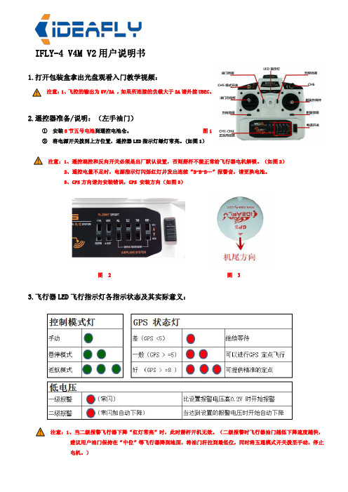
IFLY-4V4M V2用户说明书1.打开包装盒拿出光盘观看入门教学视频:注意:1、飞控的输出为5V/2A,如果所连接的负载大于2A请外接UBEC。
2.遥控器准备/说明:(左手油门)①安装8节五号电池到遥控电池仓。
图1②将电源开关拨到上方位置,遥控器LED指示灯绿灯常亮。
(如图1)注意:1、遥控混控和反向开关必须是出厂默认设置,否则掰杆不能正常给飞行器电机解锁。
(如图2)2、遥控电量不足时,电源指示灯闪烁红灯并发出连续“B-B-B…”报警音,请更换电池。
3、GPS方向请勿安装错误,GPS安装方向(如图3)图2图33.飞行器LED飞行指示灯各指示状态及其实际意义:注意:1、当二级报警飞行器下降“红灯常亮”时,此时掰杆开机无效。
(二级报警时飞行器油门越低下降速度越快,建议用户油门保持在“中位”等飞行器降到地面,将油门杆拉到最低位,同时将五通模式开关拨至手动,停止电机。
)4.复位陀螺仪由于环境温度改变、振动或其他外部环境因素可能导致陀螺仪中点漂移,中点漂移时有如下现象:飞行器上电后LED白灯常亮3s;(如图右图1)右图12)飞行器起飞后往一边倾斜,您可以通过以下方法复位陀螺仪中点。
1、必须先将飞行器放于水平地面并保持静止状态2、将飞行器通电3、手动飞行模式和返航降落飞行模式间切换四次(如图右图2),此时LED飞行指示灯白灯常亮(如图右图3)。
右图24、等待白色LED熄灭,陀螺复位完成。
注意:1、在陀螺初始化过程,需要保持飞行器静止不动。
右图35.指南针校准注意:1、请不要在含磁铁性物质的区域校准,如磁矿,停车场...2、校准时请勿随身携带铁磁物质,如钥匙,手机...将飞行器放平,然后把飞行器缓慢地水平转八圈(如图A),将飞行器放于水平地面并保持静止状态,在五通模式开关按手动模式->返航降落模式->手动模式之间快速来回拨四次以上(如图B).直到LED白灯常亮,等待白色LED熄灭指南针校准完成。
GPS导航设备说明书
Entering Personal Addresses..... 53 Updating a Personal Address..... 57 Selecting a Personal Address As
Selecting by Today's Destinations......... 39 Adding Destinations To The List......39 Selecting Destinations From the List...... 40 Editing the List............................ 41
Alphabetical Index User Agreement
Nnts
Refer to 2002 TL Owner's Manual for more information.
Introduction........................................ 2 Important Safety Information...... 3
Traveling To Your Destination...... 42 The Map Screen .......................... 46 Save Current Location ................ 47 Landmark Icons........................... 49 Going Off the Route.................... 49 Modifying the Route................... 50
Hurricane Haze 4D用户手册说明书

User ManualT ABLE OF C ONTENTS1. Before You Begin (1)What Is Included (1)Unpacking Instructions (1)Claims (1)Text Conventions (1)Symbols (1)Disclaimer (1)Product at a Glance (2)Safety Notes (2)2. Introduction (3)Product Overview (3)Product Dimensions (3)3. Setup (4)AC Power (4)Fuse Replacement (4)Mounting (5)Orientation (5)Rigging (5)4. Operation (6)Hurricane Haze 4D Control Priority (6)Control Panel Operation (6)Manual Control Knobs (6)Menu Map (6)Configuration (DMX) (6)Starting Address (6)DMX Channel Assignments and Values (6)Wired Timer Remote Setup (7)Wired Timer Remote Operation (7)5. Maintenance and Storage (8)Hazer Maintenance (8)Storage (8)6. Technical Specifications (9)7. Returns (10)7. Contact Us (11)1. B EFORE Y OU B EGINWhat Is IncludedUnpacking InstructionsCarefully unpack the product immediately and check the container to make sure all the parts are in the package and are in good condition.ClaimsIf the box or the contents (the product and included accessories) appear damaged from shipping, or show signs of mishandling, notify the carrier immediately, not Chauvet. Failure to report damage to the carrier immediately may invalidate your claim. In addition, keep the box and contents for inspection.For other issues, such as missing components or parts, damage not related to shipping, or concealed damage, file a claim with Chauvet within 7 days of delivery.Text ConventionsSymbolsDisclaimerChauvet believes that the information contained in this manual is accurate in all respects. However,Chauvet assumes no responsibility and specifically disclaims any and all liability to any party for any loss, damage or disruption caused by any errors or omissions in this document, whether such errors oromissions result from negligence, accident or any other cause. Chauvet reserves the right to revise the content of this document without any obligation to notify any person or company of such revision, however, Chauvet has no obligation to make, and does not commit to make, any such revisions. Download the latest version from .The works of authorship contained in this manual, including, but not limited to, all design, text and images are owned by Chauvet.© Copyright 2016 Chauvet & Sons, LLC. All rights reserved.Electronically published by Chauvet in the United States of America.CHAUVET, the Chauvet logo, and Hurricane Haze 4D are registered trademarks or trademarks of Chauvet & Sons LLC (d/b/a Chauvet and Chauvet Lighting) in the United States and other countries. Other company and product names and logos referred to herein may be trademarks of their respective companies.•Hurricane Haze 4D •Power Cord•Wired Timer Remote•Hanging Bracket with Mounting Hardware •Warranty Card•Quick Reference GuideProduct at a Glance•Not intended for permanent installations.•Always connect the product to a grounded circuit to avoid the risk of electrocution.•Always disconnect this product from the power source before cleaning it or replacing the fuse.•Make sure the power cord is not crimped or damaged.•Never disconnect the power cord by pulling or tugging on the cord.•If mounting this product overhead, always secure it to a fastening device using a safety cable.•Do not mount this product on a flammable surface (e.g., wood, linoleum, carton, plastic, or carpet).•Make sure there are no flammable materials close to the unit while operating•Do not touch the output nozzle on this product. It is very hot during operation and it may remain hot for several hours after turning the unit off.•Do not drink the haze fluid. If you do, call your local emergency service (911 in the US) for help.•Do not add perfume, alcohol, gasoline, or any other flammables to the haze fluid.•Depending on the amount of haze generated, all haze machines may set off smoke detectors.•In certain environments, haze fluid-based machines may leave a slippery residue on floors and surfaces.•Do not use for space heating purposes.•Use only CHAUVET DJ water-based haze fluid.•Drain the tank before transporting the product.•Always make sure that the voltage of the outlet to which you are connecting the product is within the range stated in the decal or rear panel of the product.•This product is for indoor use only! To prevent risk of fire or shock, do not expose this product to rain or moisture.•Always install this product in a location with adequate ventilation, at least 20 in (50 cm) from adjacent surfaces.•Be sure that no ventilation slots on the unit’s housing are blocked.•Never connect this product to a dimmer or rheostat.•Make sure to replace the fuse with another of the same type and rating.•Never carry the product from the power cord or any moving part. Always use the hanging/ mounting bracket.•The maximum ambient temperature (Ta) is 104 °F (40 °C). Do not operate this product at higher temperatures.•In the event of a serious operating problem, stop using the product immediately.•Never try to repair this product. Repairs carried out by unskilled people can lead to damage or malfunction. Please contact the nearest authorized technical assistance center.•To eliminate unnecessary wear and improve its lifespan, during periods of non-use completely disconnect the product from power via breaker or by unplugging it.Keep this User Manual for future use. If you sell the product, be sure that the purchaser receives this document.2. I NTRODUCTIONProduct OverviewProduct DimensionsFluid TankBlower FanDMX In/OutHaze Output KnobRemote InPower SwitchPower In Fuse HolderFan Speed KnobMenu ButtonsLED Display3. S ETUPAC PowerThe Hurricane Haze 4D has a fixed voltage power supply and it can work with an input voltage of either 120 VAC, 60 Hz or 230 VAC, 50 Hz, depending on the specific model.To determine the product’s power requirements (circuit breaker, power outlet, and wiring), use the current value listed on the label affixed to the product’s back panel, or refer to the product’s specifications chart. The listed current rating indicates the product’s average current draw under normal conditions.Fuse Replacement1.Wedge the tip of a flat-head screwdriver into the slot of the fuse holder.2.Pry the fuse holder out of the housing.3.Remove the blown fuse from the holder and replace with a fuse of the exact same type and rating.4.Insert the fuse holder back in place and reconnect power.•Always connect the product to a protected circuit (a circuit breaker or fuse).Make sure the product has an appropriate electrical ground to avoid the risk of electrocution or fire.•To eliminate unnecessary wear and improve its lifespan, during periods of non-use completely disconnect the product from power via breaker or by unplugging it.Never connect the product to a rheostat (variable resistor) or dimmer circuit, even if the rheostat or dimmer channel serves only as a 0 to 100% switch.Disconnect the product from the power outlet before replacing the fuse.Safety capSpare fuse holder(inside safety cap)Installed fuse(held by plastic clip)MountingBefore mounting the product, read and follow the safety recommendations indicated in the Safety Notes .OrientationRigging•Before deciding on a location, always make sure there is easy access to the product for maintenance and fluid replenishment.•Make sure adequate ventilation is provided around the product.•Make sure that the structure or surface onto which you are mounting the product can support the product’s weight. (see the Technical Specifications )•When mounting the product overhead, always use a safety cable. Mount the product securely to a rigging point, such as an elevated platform or a truss.•When rigging the product onto a truss, you should use a mounting clamp of appropriate weight capacity. The bracket has 13-mm holes, which are appropriate for this purpose.•The rubber feet also serve as floor supports and allow for surface mounting. When mounting the product on the floor, make sure that the product and cables are away from people and vehicles.Mounting DiagramThis product may NOT be tilted. This product should be level when on a surface or when mounted.While operating the Hurricane Haze 4D, make sure there is adequate haze fluid in the machine to prevent pump and heater damage. When the haze fluid levelbecomes low, simply add more haze fluid to continue using the Hurricane Haze 4D.Mounting BracketSafety Cable(such as CH-05 fromChauvet)Mounting Clamp(such as CLP-15 or CLP-15Nfrom Chauvet)BracketAdjustable ScoopFluid Level IndicatorRubber Feet for Floor Mounting(x4)4. O PERATIONHurricane Haze 4D Control PriorityThe Hurricane Haze 4D operates according to the following priority control levels:Control Panel OperationTo access the control panel functions, use the four buttons located underneath the display, and the two manual control knobs located to the right of the display. Please refer to the Product Overview to see the button and knob locations on the control panel.Manual Control KnobsThe manual control knobs allow for operation of the Hurricane Haze 4D without a controller.Configuration (DMX)The Hurricane Haze 4D works with a DMX controller. Information about DMX is in the CHAUVET DMX Primer, which is available from the Chauvet website/downloads/DMX_Primer_rev05_WO.pdf .Starting AddressWhen selecting a starting DMX address, always consider the number of DMX channels the selected DMX mode uses. If you choose a starting address that is too high, you could restrict the access to some of the product’s channels.The Hurricane Haze 4D uses 2 DMX channels, which defines the highest configurable address to 511.If you are not familiar with the DMX protocol, download the DMX Primer from .To select the starting address, do the following:1.Press <MENU> repeatedly until d _ _ _shows on the display.e <UP> or <DOWN> to select the starting address.3.Press <ENTER>.DMX Channel Assignments and Values1. A DMX controller takes the highest priority, and will override both the Wired TimerRemote and the manual control knobs.2.The manual control knobs will override the Wired Timer Remote, but not a DMXcontroller.3.The Wired Timer Remote has the lowest priority.Wired Timer Remote SetupThe Wired Timer Remote allows you to automatically trigger haze output by setting output, interval time, and duration time. LED indicator lights display the machine and controller’s current state. Rotary knobs set interval, output, and duration times, while manual and continuous buttons allow overriding control.1.Plug in the haze machine to power.2.Plug in the wired timer controller to the Remote socket on the back of the haze machine. (See theProduct Overview .)3.Allow the Hurricane Haze 4D three to four minutes to heat up before continuing.Wired Timer Remote OverviewWired Timer Remote OperationThe Wired Timer Remote has three modes of operation: timer, continuous, and manual.Timer ModeTo trigger the Hurricane Haze 4D with the timer function, follow the instructions below:1.Set the desired output level with the OUTPUT knob.2.Set the INTERVAL and DURATION knobs to the desired positions.•The INTERVAL knob sets the amount of time in between bursts of haze.•The DURATION knob sets the length of time that the haze machine will run during the burst.3.Press the <TIMER ON/OFF> latching button. The LED indicator above the button will light up.The timer will now run as set by the INTERVAL , DURATION , and OUTPUT knobs.4.Press the <TIMER ON/OFF> button again to turn off the timer.Continuous ModeTo trigger the Hurricane Haze 4D to continuously cycle haze, follow the instructions below:1.Set the desired output level with the OUTPUT knob.2.Press the <CONTINUOUS> latching button. The LED indicator above the button will light up. Thehaze machine outputs haze until the <CONTINUOUS> button is pressed again.3.Press the <CONTINUOUS> button again to stop the haze output.Manual ModeTo trigger the Hurricane Haze 4D manually, do the following:1.Set the desired output level with the OUTPUT knob.2.Press and hold the <MANUAL> button on the Wired Timer Remote. The LED indicator above thebutton will light up. The haze machine will output haze for as long as you hold down the <MANUAL> button.3.Release the <MANUAL> button to stop the haze output.The MANUAL Button will override the timer function.•The duration of Continuous haze output is based on the capacity of the tank.•Fluid consumption will be significantly increased during Continuous mode.INTERVAL KnobOUTPUT Knob TIMER ON/OFF Button DURATION KnobMANUAL ButtonCONTINUOUS Button5. M AINTENANCE AND S TORAGEHazer MaintenanceDo not allow the hazer to become clogged. After every 40 hours of continuous operation, use CHAUVET Fog Cleaner Quart (FCQ) through the system to prevent the accumulation of particulate matter in the heating element.The recommended cleaning procedure is as follows.1.Unplug the product from power.2.Empty all haze fluid from the machine.3.Add cleaning solution to the tank.4.Connect the product to power and allow it to warm up.5.Run the unit in a well-ventilated area until the tank is almost empty. Do not allow the pump to rundry.6.Refill with haze fluid to continue using the hazer. Run the machine briefly to clear any remainingcleaning solution from the pump and heater.StorageBefore storing the hazer, run FCQ through the system as described in the cleaning procedure above; however, only follow steps 1 through 5. Do not refill the tank with haze fluid if storing the hazer . Cleaning the system prior to storage will help prevent any particles from condensing inside the pump or heater while not in use.Powering off the unit for transportFollow these instructions to prevent leaks, and allow the air pump to entirely clear the fluid line and heater of the haze fluid before power off.Do Not operate the machine without fluid at any time.Fog Cleaner Quart (FCQ) was specifically developed by Chauvet to clean your Hurricane Haze 4D. Make sure you use FCQ regularly, no longer than 90 days between cleanings, to increase the life of your product.Test-run your Hurricane Haze 4D on a monthly basis to achieve the best performance.To prevent spills or leaks before, during, or after transport, Chauvet recommends the following steps for your Hurricane Haze 4D:1.Turn the "Haze Volume " output to off.2.Wait 30-45 seconds.3.When there is no more haze fluid in the output line, turn off the machine by pressingthe power switch.6. T ECHNICAL S PECIFICATIONSDimensions and WeightNote : Dimensions in inches rounded to the nearest decimal digit.PowerOperationFog OutputThermalDMXOrderingL ENGTHW IDTHH EIGHTW EIGHT 11 in (277 mm)15.5 in (396 mm)9.6 in (245 mm)13.2 lb (6 kg)P OWER S UPPLY T YPER ANGEV OLTAGE S ELECTIONModel-specific 120 VAC, 60 Hz, or 230 VAC, 50 HzFixed P ARAMETER 120 V, 60 H Z 230 V, 50 H Z Consumption 1120 W 1120 W Operating Current8.1 A 4.8 A Fuse F 15 A, 250 V F 15 A, 250 V P OWER I/OU.S./W ORLDWIDEUK/E UROPEPower input connector IECIEC Power Cord plugEdison (U.S.)Local Plug H EAT -U P T IMET ANK C APACITY F LUID C ONSUMPTION2 min9 gal (3.75 l)10 ml/minO UTPUT 4300 cfmM AXIMUM E XTERNAL T EMPERATUREC OOLING S YSTEM104 °F (40 °C)Convection I/O C ONNECTORC HANNEL R ANGE3-pin XLR2P RODUCT N AMEITEM CODE UPC N UMBER Hurricane Haze 4D (120 V)05071211781462215590Hurricane Haze 4D (230 V)05071212781462215606R ETURNSIn case you need to get support or return a product:•If you are located in the U.S., contact Chauvet World Headquarters.•If you are located in the UK or Ireland, contact Chauvet Europe Ltd.•If you are located in Mexico, contact Chauvet Mexico.•If you are located in Benelux, contact Chauvet Europe BVBA.•If you are located in any other country, DO NOT contact Chauvet. Instead, contact your localdistributor. See for distributors outside the U.S., UK, Ireland, Mexico, or Benelux.Call the corresponding Chauvet Technical Support office and request a Return Merchandise Authorization (RMA) number before shipping the product. Be prepared to provide the model number, serial number, and a brief description of the cause for the return.Send the merchandise prepaid, in its original box, and with its original packing and accessories. Chauvet will not issue call tags.Clearly label the package with the RMA number. Chauvet will refuse any product returned without an RMA number.Before sending the product, clearly write the following information on a piece of paper and place it inside the box:•Your name •Your address •Your phone number •RMA number • A brief description of the problemBe sure to pack the product properly. Any shipping damage resulting from inadequate packaging will be your responsibility. FedEx packing or double-boxing are recommended.If you are located outside the U.S., UK, Ireland, Mexico, or Benelux, contact yourdistributor of record and follow their instructions on how to return Chauvet products to them. Visit our website for contact details.Write the RMA number on a properly affixed label. DO NOT write the RMA number directly on the box.Chauvet reserves the right to use its own discretion to repair or replace returnedproduct(s).C ONTACT U SVisit the applicable website above to verify our contact details and instructions to request support.Outside the U.S., United Kingdom, Ireland, Mexico or Benelux, contact the dealer of record.Sunrise, FL 33351Fax: (954) 756-8015Voice: (954) 577-4455Email: ************************Fax: (954) 929-5560Toll Free: (800) 762-1084Email: *************************9770 KruishoutemBelgiumwww.chauvetlighting.euVoice: +32 9 388 93 97Email: **************************Brookhill Road Industrial EstatePinxton, Nottingham, UKNG16 6NTVoice: +44 (0) 1773 511115Fax: +44 (0) 1773 511110Industrial LermaEmail: ********************.mxLerma, Mexico C.P . 52000Voice: +52 (728) 285-5000.mx。
soyea 4g cpe 3 product faqs说明书

4G CPE 3 Product FAQs1 Modify the IP address of the WAN/LANportThe IP address of the WAN port is automatically obtained from the upstream networkand cannot be changed, except for the static IP mode, which needs to obtain the IPaddress from the carrier. The IP address of the LAN port can be changed as follows:1.Connect your computer to the CPE's Wi-Fi (or to the CPE's LAN port using anEthernet cable). Enter 192.168.8.1 in the address box of the browser, and enterthe login password to access the management page of the CPE.2.Go to Advanced > Router> DHCP. In the LAN IP address field, enter the newIP address, and click Save. To access the web-based management page, enterthe new IP address in the address bar of a browser.3.To change the network segment of the IP address pool, for example, from192.168.8.* (* ranges from 100 to 200 by default) to 10.10.10.* (* ranges from100 to 200 by default), you can directly change LAN IP address to 10.10.10.1. Inthis case, the DHCP IP range is automatically changed to10.10.10.100–10.10.10.200. You can also manually change DHCP IP range to avalue ranging from 10.10.10.2 to 10.10.10.254.If you only want to change the value of * in 192.168.8.*, you can directly change the start and end IP addresses in DHCP IP range.4G CPE 3 Product FAQs 2 Disable or enable Wi-Fi2 Disable or enable Wi-Fi1.Connect your computer to the CPE's Wi-Fi (or to the CPE's LAN port using anEthernet cable). Enter 192.168.8.1 in the address box of the browser, and enterthe login password to access the management page of the CPE.2.Go to Wi-Fi Settings > Wi-Fi Basic Settings, check Wi-Fi, then click OK in thedisplayed dialog box to disable Wi-Fi. If the checkbox next to Wi-Fi turns blue, itindicates that Wi-Fi is enabled. Wi-Fi is enabled by default.●To enable Wi-Fi again, connect your computer to the LAN port of the CPE using a networkcable, and then log in to the web-based management page to enable Wi-Fi. It isrecommended that you keep Wi-Fi enabled.●After the CPE is restored to factory settings, Wi-Fi is automatically enabled. However, allconfiguration parameters are cleared after the restoration. In this case, you will need to setthe parameters again.4G CPE 3 Product FAQs 3 Set the Wi-Fi encryption mode of the CPE 3 Set the Wi-Fi encryption mode of theCPE1.Connect your computer to the CPE's Wi-Fi (or to the CPE's LAN port using anEthernet cable). Enter 192.168.8.1 in the address box of the browser, and enterthe login password to access the management page of the CPE.2.Go to Wi-Fi Settings > Wi-Fi Basic Settings, expand the Security modedrop-down list box, select the required mode, and click Save.4G CPE 3 Product FAQs 4 Set the dynamic domain name system4 Set the dynamic domain name system1.Connect your computer to the CPE's Wi-Fi (or to the CPE's LAN port using anEthernet cable). Enter 192.168.8.1 in the address box of the browser, and enterthe login password to access the management page of the CPE.2.Go to Advanced > Router> DDNS. Click Add DDNS, enter the Domain Name,User name, and Password provided by the carrier, and click Save.Consult your carrier if you have any queries about the Domain Name, User name, andPassword.4G CPE 3 Product FAQs 5 Enable or disable the firewall5 Enable or disable the firewall1.Connect your computer to the CPE's Wi-Fi (or to the CPE's LAN port using anEthernet cable). Enter 192.168.8.1 in the address box of the browser, and enterthe login password to access the management page of the CPE.2.Go to Advanced > Security > Firewall and check Enable firewall to enable thefirewall function, or uncheck Enable firewall to disable the firewall.6 Set the mobile data limit 1.Connect your computer to the CPE's Wi-Fi (or to the CPE's LAN port using anEthernet cable). Enter 192.168.8.1 in the address box of the browser, and enter the login password to access the management page of the CPE.2.Go to Tools > Statistics, and click .3.Set the upper data limit and click Save.Your device will not disconnect from the Internet after the data usage reaches the limit you set,but will only notify you that the data usage has exceeded the limit. Additional charges may applyif you continue consuming data.4G CPE 3 Product FAQs 7 Change the login password7 Change the login password1.Connect your computer to the CPE's Wi-Fi (or to the CPE's LAN port using anEthernet cable). Enter 192.168.8.1 in the address box of the browser, and enterthe login password to access the management page of the CPE.2.Go to Advanced > System > Modify Password, enter the Current password,New password, and Confirm password, and click Save.8 Configure the virtual server 1.Connect your computer to the CPE's Wi-Fi (or to the CPE's LAN port using anEthernet cable). Enter 192.168.8.1 in the address box of the browser, and enter the login password to access the management page of the CPE.2.Go to Advanced> Security > Virtual Server, and click the + icon to access thevirtual server configuration page.3.Enter Name, Protocol, WAN Port, Device, LAN IP Address, and LAN Port,and click Save to complete configuration.A maximum of 32 virtual servers can be configured.9 Configure special applications Special applications let you use the special features over the LAN such as online games, video calls, and IP calls.1.Connect your computer to the CPE's Wi-Fi (or to the CPE's LAN port using anEthernet cable). Enter 192.168.8.1 in the address box of the browser, and enter the login password to access the management page of the CPE.2.Go to Advanced > Security > Special Applications, click + to access thespecial app configuration page, enter the Name, Trigger Protocol, Trigger Port, Open Protocol, and Open Port, and click Save to complete configuration.● For details about the parameters, contact the corresponding application provider.●A maximum of 16 special applications can be configured.10 Enable or disable the data serviceBy default, the data service function is enabled for the CPE. After the CPE registersfor the Internet, it automatically initiates a dial-up connection. You can manuallydisable this function and manually enable it when you need to access the Internet.1.Connect your computer to the CPE's Wi-Fi (or to the CPE's LAN port using anEthernet cable). Enter 192.168.8.1 in the address box of the browser, and enterthe login password to access the management page of the CPE.2.Go to Network Settings > Mobile Network > Internet Connection. Disable theMobile data switch to disable the data service. In this case, the CPE willdisconnect from the network.the data service. The CPE will re-initiate a dial-up connection.11 Create an APN list Create a profile on the management page. After the CPE successfully dials up, it can connect to the Internet in wireless mode.1.Connect your computer to the CPE's Wi-Fi (or to the CPE's LAN port using anEthernet cable). Enter 192.168.8.1 in the address box of the browser, and enter the login password to access the management page of the CPE.2.Go to Network Settings > Mobile Network > Internet Connection, and click +.3.Set the following parameters and click Save.Contact the carrier to obtain the APN, User name, and Password.4G CPE 3 Product FAQs 12 Configure the NAT function12 Configure the NAT functionNAT is a process in which the source and destination IP addresses of an IP packet arechanged when the IP packet passes through a router or firewall. The purpose of thisprocess is to translate internal (private) IP addresses into external (public) IPaddresses to prevent IP address exhaustion. The CPE supports port-restricted coneNAT and symmetric NAT. You can set NAT parameters as required.1.Connect your computer to the CPE's Wi-Fi (or to the CPE's LAN port using anEthernet cable). Enter 192.168.8.1 in the address box of the browser, and enterthe login password to access the management page of the CPE.2.Go to Advanced > Security > NAT Settings, and select Symmetric or Cone.13 Configure the VPN clientA virtual private network (VPN) is an enterprise network established on the publicnetwork. The enterprise network has the same security, management, and functionsas the private network. It can be considered as a virtual private line of an enterprise.For example, a user can connect to the intranet of the enterprise through the VPNnetwork in another area, and the data will be encrypted.Prerequisites1.Apply for an available VPN account. For details about the VPN account, contactthe VPN service provider.2.The CPE dials up successfully and can access the Internet.Method 1: Configuring the L2TP VPN client1.Connect your computer or phone to the CPE's Wi-Fi (or connect your computer tothe CPE's LAN port using an Ethernet cable). Enter 192.168.8.1 in the addressbox of the browser, and enter the login password to access the managementpage of the CPE.2.Go to Advanced > Router > VPN.3.Click Enable VPN to enable the VPN function of the router, and set Connectiontype to L2TP VPN client.1.The parameter values in the following figure are for reference only. Set the parametersbased on the actual VPN account.2.When L2TP is used for VPN dial-up, the entered parameters must be the VPN serverparameters of the L2TP type. Otherwise, the dial-up will fail.4. Click Save . If the Connection Status is Connected , it indicates that the VPN issuccessfully connected.Method 2: Configuring the PPTP VPN client1. Connect your computer or phone to the CPE's Wi-Fi (or connect your computer tothe CPE's LAN port using an Ethernet cable). Enter 192.168.8.1 in the addressbox of the browser, and enter the login password to access the managementpage of the CPE.2. Go to Advanced > Router > VPN .3. Click Enable VPN to enable the VPN function of the router, and set Connectiontype toPPTP VPN client .When PPTP is used for VPN dial-up, the entered parameters must be the VPN serverparameters of the PPTP type. Otherwise, the dial-up will fail.4.Click Save. If the Connection Status is Connected, it indicates that the VPN issuccessfully connected.4G CPE 3 Product FAQs 14 Modify the Wi-Fi name and password14 Modify the Wi-Fi name and password1.Connect your computer to the CPE's Wi-Fi (or to the CPE's LAN port using anEthernet cable). Enter 192.168.8.1 in the address box of the browser, and enterthe login password to access the management page of the CPE.2.Go to Wi-Fi Settings > Wi-Fi Basic Settings to view the current Wi-Fi name andpassword. Enter the new Wi-Fi name (SSID) and Wi-Fi password, and clickSave.15 Set the Wi-Fi blocklist and trustlistAfter Wi-Fi access control is enabled, you can set the Wi-Fi of the CPE to blocklistmode or trustlist mode as required. In blocklist mode, devices in the blocklist cannotconnect to the CPE. In trustlist mode, only devices in the trustlist can connect to theCPE. Setting the Wi-Fi blocklist and trustlist enhances network security. The CPE canrestrict user access even if someone knows your Wi-Fi name and password.1.Connect your computer to the CPE's Wi-Fi (or to the CPE's LAN port using anEthernet cable). Enter 192.168.8.1 in the address box of the browser, and enterthe login password to access the management page of the CPE.2.Go to Advanced > Wi-Fi > Wi-Fi MAC Filter. Enable Wi-Fi MAC Filter. Set theCPE to blocklist mode (Block the access of devices in the list) or trustlist mode(Allow the access of devices in the list) as required.3.Set Filter mode to Block or Allow, and click to add Wi-Fi devices to theWi-Fi MAC address list. Then click Save.After the devices are added, you can view them in the Wi-Fi MAC address list.If you do not want to use the blocklist or trustlist function, disable Wi-Fi MAC Filter.16 Set parental controls The CPE supports the parental control feature to control the network access permission of devices.1.Connect your computer to the CPE's Wi-Fi (or to the CPE's LAN port using anEthernet cable). Enter 192.168.8.1 in the address box of the browser, and enter the login password to access the management page of the CPE.2.Go to Tools > Parental Control, and click +.3.Select the desired time period, week, and device (displayed as a device name),and click Confirm.。
GPS安全监护手机使用说明书
GPS安全监护手机使用说明书欢迎使用感谢您选择GPS安全监护手机手机。
该部手机是GSM与GPS 技术的完美结合,流线型时尚外观设计,简洁高雅;充分展示时尚个性;大容量电话簿、短信息、闹钟、通话中心,话机设置,调频广播,GPS定位,挂机状态紧急报警等实用功能,助您享受生活的丰富多彩。
●请仔细阅读本手册后, 再使用本手机。
●新购买的手机,在首次使用前需先充电12小时,并且在第一次电量完全耗尽后,再进行第二次充电。
如此反复使用几次后,电池将达到最佳使用效果。
本款手机说明书内容与实物可能存在差异,请以实物为准。
若本款手机及其附件有任何更新,本公司恕不另行通知。
目录1.安全警告和注意事项 41.1 安全防范措施 41.2 使用手机的注意事项 51.3使用电池的注意事项51.4 使用充电器的注意事项 61.5 有关要求72.使用须知92.1.检查手机及配件92.2.手机规格92.2.1配件规格 92.2.2技术规格 92.3.外观 102.4 .如何插入SIM卡112.5 电池112.5.1 安装电池112.5.2充电113.基本操作133.1.开关机133.2 .待机快捷操作133.3.按键锁定133.4.调节听筒音量 143.5.文字输入143.5.1.输入汉字错误!未定义书签。
3.5.2.输入字母错误!未定义书签。
3.5.3.输入数字错误!未定义书签。
4.功能结构144.1.电话簿144.1 .1查找154.1.2 新增154.1.3 复制154.1.4 设置154.2.短消息154.2.1写消息154.2.2 收件箱164.2.3 发件箱164.2.4 短信设置164.3.通话中心164.4.话机设置164.5.工具 165.手机的保养176.故障查找187.关于GPS部分使用说明197.1与GPS相关功能接受197.2基本功能具体对应指令及操作方法19 7.2.1.位置查询19(1)短信查询19(2)平台查询207.2.2.中心号码设定217.2.3.双向通话功能217.2.4.SOS求助功能217.2.5.定时上传间隔设定227.2.6.修改密码功能227.2.7.低电压报警功能227.2.8.设置接入点指令237.2.9.电子围栏功能23(1)GPS围栏功能23(3)围栏读取功能23(4)取消围栏功能247.2.10.辅助功能:248.售后服务25注意事项: 251.安全警告和注意事项1.1 安全防范措施使用手机之前,请仔细阅读过“安全警告和注意事项”以后,再正确地使用该手机。
GALILEO HUD 产品说明书

GALILEO1ST THING: Attach the protective foil (included in the package) to preserve screen quality. IMPOR T AN T : In order to switch on the GALILEO HUD for the first time a power connection is needed. NOTE: Make sure that the GALILEO HUD is switched on while the battery is charging.GALILEO HUD Push-Wheel User Controls:1 ) Rotate.2 )P ress-and-Release.(The act of pressing and quickly releasing the push-wheel.)3 ) P ress-and-Hold. (The act of pressing and holding the push-wheel for 1 second before release.)QUICK USE GUIDE■ T o operate the push-wheel, simply rotate it to navigate screen to screen, or up and down within a menu, or to increase or decrease a user setting.■ A press-and-release of the push-wheel turns on the GALILEO HUD , takes you to the main menu, lets you enter the various sub-menus, select functions and save settings .■ A press-and-hold allows you to return to previous menus or screens, edit settings and, from the surface screen, turn the GALILEO HUD off.■ Screen prompts indicate what type of press is required to accomplish each function. HUD TIPSMAIN MENUGAS› Air › Nitrox › TrimixCHARGE YOUR BATTERY!■ Your GALILEO HUD is delivered to you in a deep sleep mode. This is done to preserve battery life and ensure your GALILEO HUD arrives with a fresh battery.■ R EMINDER: I n order to switch on the GALILEO HUD for the first time a power connection is needed. After this initial activation, the GALILEO HUD will never again return to deep sleep mode. Make sure the GALILEO HUD is switched on while the battery is charging.■ Your GALILEO HUD must be fully charged before using the computer for the first time.CHECK YOUR BATTERY.■ Your GALILEO HUD is powered by a rechargeable Li-Ion battery.■ Always fully charge the battery before each dive.WARNING!When your GALILEO HUD ’s battery reaches the end of its lifetime, it can be replaced only by an authorized SCUBAPRO service center.Do not open your HUD or try to replace the battery yourself! ■ Opening the GALILEO HUD housing will VOID YOUR WARRANTY.■ Changing the battery must be done with particular care in order to prevent water from seeping in. ■ The GALILEO HUD ’s warranty does not cover damages due to the improper placement of the battery.354:5660WRECK521 ) Mount 1st stage regulator with Smart transmitter on a full tank.2 ) T urn on your GALILEO HUD, go to the GAS menu, and select the gas you want to pair to. Apress-and-release will save your selection (indicated by an “X” in the box next to the select-ed gas) and return you to the Surface screen.3 ) Now go the TANK PAIRING menu. Press-and-release.4 ) Here the gas you selected in Step 2 will be highlighted. Press-and-release.5 ) T his will start the pairing process as a countdown timer starts.(NOTE: You can extend the timeout period by giving the push-wheel a short press.)6 ) A s the timer counts down, open the tank valve and position your GALILEO HUD close to it(see illustration). Upon pressurization, the Smart transmitter will send a pairing sequence to the GALILEO HUD, the screen will display “OK” and then revert to the Tank Pairing screen.7 ) A fter a successful pairing, on the Surface screen the tank pressure will appear in eitherBAR or PSI in the lower left hand corner, accompanied by a pressure bar running up the left side of the screen.。
思翼科技 MK32 工业级手持地面站 用户手册 V1.1说明书
MK32工业级手持地面站用户手册V1.12023.10感谢您购买思翼科技的产品。
MK32工业级手持地面站是思翼科技链路产品家族的最新成员,搭载7英寸高清高亮大屏、可扩展至30KM的双路全高清数字图传、4G运存和64G存储的顶级安卓配置,还可选购一机双控、遥控接力等特性,丰富的接口和强大的可扩展性可广泛应用于无人机、无人车船以及智能机器人等领域。
考虑到飞行安全,也为了带给您良好的产品使用体验,请您在装机、飞行前仔细查阅用户手册。
本手册可以帮助您解决大部分的使用疑问,您也可以通过访问思翼科技官方网站()与本产品相关的页面,致电思翼科技官方售后服务中心(400-8382918)或者发送邮件到****************直接向思翼科技工程师咨询产品相关知识以及反馈产品问题。
思翼科技官方QQ群说明书版本更新记录阅读提示 (8)标识、图标 (8)安全 (8)电池 (10)设备闲置、携带、回收 (10)1 产品简介 (12)1.1 产品特性 (12)1.2 部件说明 (14)1.2.1 产品概览 (14)1.2.2 按键、开关类型及通道定义 (16)1.2.3 接口与数据流 (17)1.3 技术参数 (20)1.4 物品清单 (25)1.5 状态指示灯定义 (27)1.5.1 遥控器指示灯定义 (27)1.5.2 天空端指示灯定义 (28)2 使用前 (29)2.1 地面端 (29)2.1.1 开机与关机 (29)2.1.2 充电 (29)2.1.3 充电指示灯定义 (30)2.1.4 切换系统语言 (30)2.2 提升通讯距离与视频流畅性重要说明 (34)2.2.1 使用注意事项 (34)2.2.2 不同飞行距离需求下天线选用以及无线飞行模式设置方法 (34)2.2.3 地面端标准全向天线的安装摆放方式 (35)2.2.4 地面端平板增程天线的安装摆放方式 (36)2.2.5 天空端标准全向天线的安装摆放方式 (37)2.2.6 通讯距离不理想、需要原厂技术支持前所需必要信息 (41)3 “思翼遥控”应用 (43)3.1 通道设置 (44)3.1.1 舵机行程量 (44)3.1.2 中立点调节 (44)3.1.3 舵机反向 (45)3.1.4 通道映射 (45)3.2 数传设置 (47)3.2.1 连接 (47)3.2.2 飞控 (48)3.2.3 串口波特率 (49)3.3 系统设置 (51)3.3.1 对频 (52)3.3.2 多天空端 (52)3.3.3 自适应频点 (53)3.3.4 油门杆类型 (53)3.3.5 第15通道 (54)3.3.6 无线模式 (54)3.3.7 摇杆死区 (55)3.4 链路信息 (56)3.5 失控保护 (57)3.6 按键拨轮设置 (59)3.6.1 按键设置 (59)3.6.2 拨轮设置 (59)3.7 摇杆校准 (61)3.8 拨轮校准 (64)3.9 多机互联 (67)3.9.1 遥控接力 (67)3.9.2 一机双控 (68)3.10 设备信息 (71)3.11 “思翼遥控”更新日志 (72)4 数传 (73)4.1 通过UART串口与安卓地面站通信 (73)4.1.1 极翼飞防管家 (73)4.1.2 博鹰农业 (74)4.1.3 微克智飞 (75)4.2通过USB串口与安卓地面站通信 (77)4.2.1 QGroundControl (77)4.2.2 Mission Planner (78)4.3通过蓝牙与安卓地面站通信 (80)4.3.1 QGroundControl (80)4.2.2 Mission Planner (82)4.4 通过UDP与安卓地面站通信 (84)4.4.1 QGroundControl (84)4.4.2 Mission Planner (85)4.5 通过遥控器Type-C升级接口与Windows地面站通信 (88)4.5.1 QGroundControl (88)4.5.2 Mission Planner (89)4.6 通过UDP经过遥控器WiFi热点与Windows地面站通信 (91)4.6.1 QGroundControl (91)4.6.2 Mission Planner (92)4.7 数传无法连接的解决方法 (95)4.8 数传SDK通讯协议 (97)4.8.1 协议格式说明 (97)4.8.2 通讯命令 (97)4.8.3 通讯接口 (103)4.8.4 SDK CRC16校验代码 (103)5 “SIYI FPV”应用 (107)5.1 设置菜单 (109)5.2 链路信息 (110)5.3 云台相机 (111)5.4 关于SIYI FPV (113)5.5 SIYI FPV应用更新记录 (114)6 图传 (115)6.1 思翼手持地面站配合“SIYI FPV”或思翼QGC(安卓)应用控制思翼光电吊舱/云台相机 (115)6.1.1 准备工作 (115)6.1.2 云台俯仰与平移 (117)6.1.3 变倍 (117)6.1.4 拍照与录像 (117)6.2 接入第三方网口相机或光电吊舱 (119)6.3 接入HDMI相机 (120)6.4 接入双路视频 (121)6.4.1 接入两个思翼相机或两个天空端HDMI输入模块 (121)6.4.2 接入两个第三方网口相机或光电吊舱 (121)6.4.3 接入一个思翼天空端HDMI输入模块和一个第三方网口相机或光电吊舱1216.5 设备常用参数 (123)6.6 无法显示视频图像的解决方法 (124)6.7 从遥控器输出图像至其他设备 (126)6.7.1 通过遥控器HDMI接口输出 (126)6.7.2 通过遥控器WiFi热点共享输出 (126)6.7.3 通过以太网口输出图像 (127)7 安卓系统 (132)7.1 下载应用 (132)7.2 如何导入并安装应用 (132)7.2.1 通过TF卡导入并安装 (132)7.2.2 通过U盘导入并安装 (132)7.2.3 通过Type-C文件传输功能导入并安装 (133)7.3 查看安卓固件版本 (136)8 思翼调参助手 (138)8.1 固件升级 (138)8.2 主要固件更新记录 (141)8.3 调参软件更新记录 (143)9 售后与保修 (144)9.1 返修流程 (144)9.2 保修政策 (144)9.2.1 7天包退货 (145)9.2.2 15天免费换货 (146)9.2.3 一年内免费保修 (147)阅读提示标识、图标在阅读用户手册时,请特别注意有如下标识的相关内容。
四轴飞行器说明书.doc
4-AXIS AEROCRAFT INSTRUCTION MANUAL四轴飞行器说明书ATTENTION:(注意事项)1、This 4-axis aircraft is suitable for indoor/outdoor flying.but make sure the outdoor wind is not over grade 4.这款四轴飞行器适用于室内/室外飞行。
但要确保室外风力不超过4级。
2、2.4 technology adopted for anti-interference,even more than one quadcopter is flying in the same area they will not interferewith each other.采用2.4GHZ抗干扰技术, 即使一个以上的飞行器在同一地区飞行,它们也不会彼此干扰。
Beside ,players can let the the aircraft fly up/down/forward/backward,left/right sideward and tuen left/right.此外,玩家可以让飞机飞上/下/前进/后退,左转/右转和左翻/右翻。
3、Please read this man ual carefull before using,in the mean time ,please well keep the manul for future reference.请在使用前仔细阅读本手册,同时,请妥善保管说明书备查。
ALL PARETS INCLUDED( 组成结构简介)MAIN MENU:(菜单)Lcd screen液晶屏幕Power light 电源指示灯Servos舵机Flip key 翻转Left hand throttle shows左手调节显示Forward and back left and right前,后,左,右Signal display信号指示Direction joystick方向操纵杆Accelerator and steering 油门和转向Forward/back trimming 前进/后退微调Left-turn/riggt-turn trimming 左/右转微调Left/right sideways timming左/右侧微调Power switch 电源开关TRANSMITTER BATTERY INSTALLATION:( 安装发射器电池)Aircraft battery change:( 更换飞机电池)THE RELATED NOTES ABOUT LITHIUM BATTERY’S USAGE:关于锂电池使用的相关说明HOW TO CONTROL:(操作说明)1、Aircraft power switch to the “ON”position.the vehicle-mounted with the flatground.Motherboard light is blink,don’t turn the fuselage again.飞行器电源开关拔到“ON”位置。
四通道卫星接收机说明书
四通道卫星接收机使用说明书目录1安全注意事项 (2)2概述 (3)2.1产品功能及用途 (3)2.2外形尺寸(1U机箱) (3)3主要特点 (4)4技术规格与指标 (4)4.1数据输入 (4)4.2数据输出 (5)4.2.1ASI接口 (5)4.3网络管理接口 (5)4.4辐射及安全要求 (5)5系统组成及工作原理 (5)5.1系统组成 (5)5.2工作原理 (7)6安装指南 (7)6.1安装准备 (7)6.2设备安装流程 (8)6.3环境条件要求 (8)6.4接地要求 (9)6.4.1机柜接地 (9)6.4.2设备接地 (9)6.5线缆的连接 (9)6.5.1电源线的连接 (9)6.5.2信号线的连接 (10)7前面板操作指南 (10)7.1键盘功能 (10)7.2菜单选择 (11)7.2.1锁定状态显示 (11)7.2.2主菜单显示 (11)7.2.3射频设置 (11)7.2.4网络设置 (12)7.2.5保存当前设置 (13)7.2.6加载设置 (13)7.2.7版本号 (14)7.2.8选择语言种类(中文和英文) (14)7.2.9错误信息 (14)7.3系统运行错误及排除 (14)7.3.1指示灯状态 (14)7.3.2常见故障排除 (15)8网络管理器操作指南 (15)8.1NMS登陆 (16)8.2添加频点 (17)8.3添加设备 (18)8.4修改设备 (19)8.5查看和设置设备参数 (21)8.5.1卫星参数 (22)8.5.2信号监测 (23)8.6网管软件公共功能 (23)前言感谢您选用本公司的产品。
本手册详细介绍了产品的性能、安装及操作方法,无论您是第一次使用该产品,还是以前接触过很多类似产品,都必须在使用前仔细阅读本手册。
收货检查打开设备包装箱校验物品,务必检查小部件的包装材料,对照产品装箱清单或者下列项目检查包装箱中的物品:四通道卫星接收机 1台交流输入电源插线 1根ASI 线 1根如果这些项目与清单不符合,请立即通知我公司。
GPS智能物流信息终端使用说明书
GPS智能物流信息终端使用说明书GPS智能物流信息终端产品使用说明书北京航天智科信息技术目录欢迎使用 (3)第一章产品概述 (3)1产品简介 (3)2产品包装 (4)第二章特性和规格说明 (4)2.1要紧特性 (4)2.2规格 (4)2.3产品外观 (6)2.4产品操纵台主界面 (7)第三章产品供电和充电 (7)3.1供电 (7)3.2开、关机 (8)3.3重新启动系统 (8)3.4使用触摸笔 (8)3.5使用SD/MMC储备卡 (8)第四章差不多使用 (9)4.1开机主界面及要紧功能介绍 (9)4.2开/关机 (9)4.3主菜单功能表 (10)第五章详细操作指导 (11)5.1车辆装载状态操作说明 (11)5.2配货信息操作说明 (12)5.3服务中心操作说明 (13)5.4货源查询操作说明 (14)5.5导航娱乐操作说明 (16)5.6通讯功能操作说明 (21)5.7设置界面操作说明 (23)第六章简单故障处理和产品的爱护 (27)欢迎使用欢迎使用我公司货运通智能车载终端!我公司保留对此«使用手册»的最终说明权。
本产品有任何变动,恕不另行通知。
不便之处,敬请原谅!请用户将重要资料进行备份,因资料遗失造成的缺失,本公司不承担任何责任。
本手册差不多过认真核对,但不排除有少量文字错误的可能性。
如发觉,请联系本公司客户服务中心。
请先认真阅读本«使用手机»的操作说明与指示,并只使用原厂提供的配件,以免造成无法预期的损坏。
假如您未依照正确的程序使用本系统或连接不兼容的配件,此行为将导致保修自动失效,甚至可能危害您及他人的安全。
对此,本公司不承担任何责任。
由于交通建设的进展,可能显现导航电子地图数据与实际交通指示不完全一致的情形,请您务必遵照道路现状、现地标志等交通规那么行驶。
在汽车驾驶过程中查看或操作本产品,可能会导致严峻交通事故。
由于使用导致的交通意外及造成的各种缺失,本公司不承担任何责任。
- 1、下载文档前请自行甄别文档内容的完整性,平台不提供额外的编辑、内容补充、找答案等附加服务。
- 2、"仅部分预览"的文档,不可在线预览部分如存在完整性等问题,可反馈申请退款(可完整预览的文档不适用该条件!)。
- 3、如文档侵犯您的权益,请联系客服反馈,我们会尽快为您处理(人工客服工作时间:9:00-18:30)。
内部
CHA-4G型捷联航姿仪
使用说明书
中国电子科技集团公司第二十六研究所
2007年12月
内部
CHA-4G型捷联航姿仪使用说明书
1 产品概述
CHA-4G型捷联航姿仪(以下称“航姿仪”)是中国电子科技集团公司第26
研究所研制的新型组合惯性导航系统。这种高可靠性、一体化的组合惯导系统
可实时提供载体的姿态角(偏航角、俯仰角和滚动角)信息,同时它还具有体
积小、重量轻、数据更新频率高、抗冲击振动、性价比高和供电方便等特点,
可用于靶机、无人飞行器、高速战斗机吊舱等空间载体的惯性测量与控制。
CHA-4G采用了小型、低功耗的惯性组合,运用卡尔曼滤波,将SINS和GPS
的信息融合起来,提高了导航系统的精度,延长了保精度时间。
2 主要技术指标:
2.1 工作温度: -40℃~+60℃;
2.2 供电电源: 27±9V(DC);
2.3 准备时间: ≤3min;
2.4 测量范围:
偏航:0~360°;
俯仰:±85°;
横滚:±180°;
三轴角速度:±200°/s;
三轴加速度:±5g;
2.5 导航精度:
航向角精度:<0.2°(1σ)(要求速度≥2.5m/s);
俯仰精度:<0.2°(1σ);
横滚精度:<0.2°(1σ);
2.6 数据刷新率:100Hz;
3 基本原理
航姿仪由三个速率陀螺、三个加速度计、高速导航计算机及GPS组成,陀
螺测得的载体角速度信息和加速度计测得的载体加速度信息由数据采集器进行
模/数转换后被送入导航计算机,导航计算机将采样数据及GPS信息首先进行预
处理,然后运用卡尔曼滤波技术,使SINS和GPS的信息融合起来,提高导航系
内部
统的精度,并得到载体飞行过程中的航向角、俯仰角和滚动角等。导航解算
原理及过程如图1所示。
图1:导航解算原理及过程
4 标识、产品外型及尺寸
4.1 产品上铭牌轴向标识(图2)
图2: 轴向标识
4.1.1 绕X轴转动角为俯仰角,正方向按右手定则确定;
4.1.2 绕Y轴转动角为滚动角,正方向按右手定则确定;
4.1.3 绕Z轴转动角为航向角,顺时针为正;
4.2 外形结构
CHA-4G型捷联航姿仪结构特征及安装尺寸如图3所示。
加速度计 陀 螺 预处理 误差补偿 误差补偿 比力计算 速度计算 姿态矩阵 姿态角计算 信息融合、补偿 导航参数输出 GPS信息 GPS信息 位置计算
X
Y
Z
内部
向
数 量共 张标记阶段第 张比 例±0.1±0.1格式(1)制图:底图总号签名日期归底图总号媒体编号描图:幅面:标准化批 准工 艺设 计
审 核
数量标记日期更改单号签名
1.6
A
未注尺寸公差按GB/T1804- C
图3 CHA-4G型捷联航姿仪外形和安装尺寸
5 使用和维护
5.1 产品使用方法
a) 按表1进行电气连接;
b) 电气连接确认无误后,给航姿仪加电。
c) 航姿仪开始工作,数据由串行接口输入、输出。
5.2 航姿仪接插件接线分配
输入输出用JY27496E11B35SN型插座连接,对应的插头为
JY27467T11B35PN接点分配见表1。
表1 JY27496E11B35SN型插座接点分配
引脚号 定义 备注
1
电源27±9V(DC)
电源
输入 2
电源地
3 TX+
RS422串行接口
4 TX-
5 RX+
6 RX-
7~13 — 禁用
内部
Y50EXW-0810ZK10P1型插座接点分配(实验室航姿)
引脚号 定义 备注 引脚号 定义 备注
A 电源27±9V(DC) 电源输入 G-J --
禁用
B 电源地
C TX+ 串口1(RS422)
D TX-
E RX+
F RX-
5.3 软件接口说明
a) 输出参数:航姿仪导航参数
b) 接口方式:RS-422串口
c) 波特率:115200
d) 数据格式:1个开始位+8位数据位+1个停止位;
e) 数据更新周期:10ms
f) 数据帧格式:报文头(4字节)+状态(1字节)+数据(26字节)+较验
和(1字节),低字节在前,高字节在后;定义及传输顺序如表2:
表2、导航参数数据帧格式定义
数据定义 数据类型 数据长度 单位 数据内容
报头1
BYTE 1 0XEB
报头1
BYTE 1 0X90
报头1
BYTE 1 0X20
报头1
BYTE 1 0X13
状态字
BYTE 1
时(GPS时间) BYTE 1 时
分(GPS时间) BYTE 1 分
秒(GPS时间) BYTE 1 秒
毫秒(GPS时间) BYTE 1 10毫秒
经度 Long int 4 0.00001度
纬度 Long int 4 0.00001度
高度 short 2 米
东向速度 short 2 0.1米/秒
内部
北向速度 short 2 0.1米/秒
垂直速度
(向上为正)
short 2 0.1米/秒
航向角 Unsigned short 2 0.01度
俯仰角 short 2 0.01度
滚动角 short 2 0.01度
校验和(前27个数据
字节的累加和)
BYTE 1
g) 状态字定义:
bit0:工作状态位,0表示准备时间,1表示导航时间;
bit1:GPS状态位,0表示GPS无效,1表示GPS有效;
bit2:航向状态位,0表示未对准,1表示已对准;
bit3:故障状态位,0表示工作正常,1表示出现故障;
6 航姿仪工作流程及注意事项说明
6.1 航姿仪上电后,需要180s时间的准备时间,这段时间内,载体应保持基本
静止状态或匀速直线飞行,否则导航仪精度可能下降,在此期间需要收到
正常的GPS数据。
6.2 航姿仪在导航工作期间,若GPS无效,导航误差将随时间累积。
6.3 航姿仪在导航工作期间,若航向状态位输出为0,导航仪的航向输出为偏航
角,若为1,航向输出为载体与真北的夹角。
6.4 航姿仪在导航工作期间,若故障状态位输出为1,则表示航姿仪的精度下降
到指标要求以下。这时需要将航姿仪断电后重新上电,以达到指标要求精
度。
7 使用、储存和运输注意事项
7.1 通电前应严格检查供电,确认无误方可通电工作,否则会导致导航仪工作
不正常,甚至永久性损坏。
7.2 本产品属精密仪器,严禁在使用、运输中碰撞、跌落损伤;运输过程中应
避免大冲击。储存在环境温度为-55℃~+85℃,相对湿度不大于80%,周
围环境无酸性及有害气体的库房中。