Adaptive steering control for combined vehicles with steer-by-wire system
美船Mercury Marine SCC-1 智能船用控制器安装手册说明书
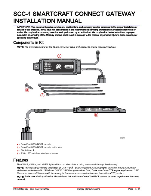
SCC-1 SMARTCRAFT CONNECT GATEWAY INSTALLATION MANUALIMPORTANT: This document guides our dealers, boatbuilders, and company service personnel in the proper installation or service of our products. If you have not been trained in the recommended servicing or installation procedures for these or similar Mercury Marine products, have the work performed by an authorized Mercury Marine dealer technician. Improper installation or servicing of the Mercury product could result in damage to the product or personal injury to those installing or operating the product.Components in KitNOTE: The termination band on the 10‑pin connector cable only applies to engine mounted modules.a -SmartCraft CONNECT moduleb -SmartCraft CONNECT module ‑ side viewc -Cable ties ‑ 4d -#10 x .88" stainless steel wood screwFeaturesThe CAN P, CAN H, and NMEA lights will turn on when data is being transmitted through the Gateway.NOTE: This manual covers the installation of CAN P only ‑ engine mounted module (single). The helm mount module will default out of the box with CAN P and CAN H. CAN H is applicable to Dual, Triple, and Quad DTS engine applications. CANH must be turned off if issues with the analog tachometers are encountered on mechanical/non‑DTS products.NOTE: At the time of this publication, VesselView Link and SmartCraft CONNECT cannot be used together on the same network.SmartCraft CONNECT Module—Single through Quad‑EngineNOTE: The SmartCraft Connect module does not provide power for any device on the NMEA 2000 network. The NMEA 2000 network will require its own power source. The NMEA 2000 network power input must have appropriate circuit protection for the devices on the NMEA 2000 network.NOTE: The termination band on the 10‑pin connector cable only applies to engine mounted modules.a -CAN P connection lightb -NMEA connection lightc -CAN H connection lightd -Wi‑Fi connection lighte -Bluetooth® connection lightf -NMEA 2000® connectorg -10‑pin connectorModule Harness Connections1.Connect the SmartCraft CONNECT module in one of the two following ways:a.Connect the CAN 10‑pin harness connector to the SmartCraft junction box. Refer to the following diagram.b.Connect the CAN 10‑pin harness connector to the helm harness SmartCraft 10‑pin connection using a male‑maleadapter harness.2.Connect the module NMEA 2000 harness connector to the NMEA 2000 network. A NMEA 2000 extension may berequired to reach the NMEA 2000 backbone.a -120‑ohm termination resistorb -Chartplotterc -SmartCraft CONNECT moduled -NMEA 2000 fused power sourcee -SmartCraft junction boxOn‑Engine Mounting GuidelinesMounting RequirementsNOTE: The 10‑pin on‑engine terminator must be removed from the engine harness before installation of this module.•The SmartCraft CONNECT module must be mounted in a location that allows for connection to the 10‑pin connector on the engine harness. No additional 10‑pin harnessing may be used in the installation of this product.•All routing must adhere to harness installation bend parameter specifications. The minimum bend radius of any portion of the harness must be no less than 13 mm (0.5 in.).•Two cable ties to secure the SmartCraft CONNECT module must be used to prevent unwanted movement during normal operation of the propulsion package.•The following locations must be avoided when installing the SmartCraft CONNECT module.•Any location which can be exposed to water•Any location that is subject to high heat during operation of the power package•Near ignition coils•Near spark plug wires•Near shift/throttle cables•Where harnessing could contact belts•Secured to fuel linesModule ConfigurationIMPORTANT: Module configuration must be completed by a Mercury authorized dealer or boatbuilder. The SmartCraft Manager app is licensed to the dealer or boatbuilder.IMPORTANT: For configuration of the SmartCraft CONNECT Module, a mobile device and a Wi‑Fi connection with access to the internet is required.IMPORTANT: If using a Garmin® or Raymarine® display, visit their website to make sure the display is running the latest software available.1.Download the SmartCraft Manager app from your iOS App Store or Google Play Store.735782.After the app has been downloaded to your device, open the app to begin the configuration process.3.Begin by entering the dealer number and license number.XXXXXXXXXXXX-OOOOOO-XXXXXX-OOOOOO-XXXXXX726044.Sign in to the appropriate existing account with the email and password credentials. If this is the first time setting up aSmartCraft CONNECT, an account must be created. Save the new account credentials for future use.NOTE: Brunswick Corporation is moving all accounts to a single login. If you already have an account for 1st Mate, Mercury University, MDA, Harris® boats, Boston Whaler®, Sea Ray®, etc., your user name and password may work here.IMPORTANT: Android™ users need to grant the app permission to use location services when requested. This is a requirement to allow a full Bluetooth® connection to the module.726055.Continue entering additional data on the next screen.6.Power up the system with the key in the ON position.7.Check that the SmartCraft CONNECT module and all other items on the boat are powered up. When these conditionsare met, select Find My Device.726068.The SmartCraft CONNECT module will appear on‑screen along with a list of available Wi‑Fi networks. Select a trustednetwork and connect.NOTE: Networks that do not require a password are acceptable to use. Captive portal Wi‑Fi networks, which require a user to interact with a web page, cannot be used to configure this module.NOTE: The device name uses the last 3 digits of the module serial number for identification.NOTE: Wi‑Fi signal strength needs to be 3 bars to function properly.XXXXXXXXXX726079.Enter the network password and select Connect.7260810.The SmartCraft CONNECT device will connect. Depending on the network strength, this may take a minute.7260911.The menu screen will appear. The module will automatically query the Mercury site for any updates to the firmware. Ifany updates are needed, there will be an exclamation point in the upper right corner of the Update Firmware tile. In this event, click on that tile and any updates will begin.NOTE: The app will say update complete when the module reflash is downloaded to the module. It will then restart, and may take a few minutes to perform the update. Do not remove battery power during this time.NOTE: Complete any firmware updates before beginning the configuration process.NOTE: Wait until the Wi‑Fi LED on the device is solid, or a No Updates ‑ 'Device is not ready to receive a firmware update'. message will appear.726107411012.Select the Configuration tile on the screen.7358013.Select Configure Engines.7457914.Enter the correct information for the Engine Type, and Engine Model. Review your selections, and if everything iscorrect, select Save.15.Continue by entering the engine serial number for the engine(s) supported by the module.7261316.Next, configure the CAN H connection by following the prompts on the screen.NOTE: CAN H configuration only applies to boats with steer‑by‑wire systems; Joystick Piloting, outboard, sterndrive, or Zeus. CAN H may be active on DTS or non‑DTS applications depending on boat setup.17.Verify that the Wi‑Fi LED is solid, indicating that the device has completed a cloud sync. If this is not verified, there is nocertainty that the configuration was delivered to the module.18.For tank configuration, return to the CONFIGURATION screen, and select the Configure Tanks option and selectSTART.7405319.Select the Pencil Icon within each tank field to edit and enter tank information.7458020.Enter tank data and descriptions by selecting each option on the screen. Select SAVE after all information has beenselected or input for each tank.1 -Tank type drop‑down menu2 -NMEA instance numberNOTE: The default will be "Auto". This option will only need to be changed on boats where there are multiple sources for tank levels on the N2K network.3 -Tank volume capacity numberNOTE: A tank capacity of 0.0 will not show on the NMEA data stream. The capacity must be set greater than zero to show the tank level on NMEA.4 -Tank volume unit drop‑down menu 5 -Customizable tank name 6 -SAVE all current entries21.Repeat this process for additional tanks on the vessel before navigating out of the configuration screens.7414322.For steering angle source selection, return to the CONFIGURATION screen, and select the Steering Angle Sourceoption and select START.7458223.Select the desired steering angle source from the drop‑down menu and select SAVE .740371356NOTE: This will only display steering angle on the MFD for vessels equipped with electric steering, joystick piloting, and certain MerCruiser/diesel applications.7458324.To enable or disable Stationkeeping features, return to the CONFIGURATION screen, and select the StationkeepingFeatures option and select START.74586ing the radial slider buttons, enable or disable the desired features, and select SAVE.NOTE: This will only enable control of these features through the MFD. These controls will not add the feature to a vessel if it was not equipped. Stationkeeping features should be turned off on all applications except joystick piloting.74587Features enabled in imageTroubleshootingMobile FunctionalityIMPORTANT: When using the app on Android devices, fine location detail must be shared with the app for proper function. LED LightingNOTE: The Wi‑Fi LED status troubleshooting chart is also available in the app.74028The device contains 5 LEDs for indicating the status of CAN P, NMEA, CAN H, Wi‑Fi, and Bluetooth®.1.CAN P•Flashing: The LED will flash continuously once power is applied.•Solid: Once the bus communication is established, the LED will remain on.2.NMEA•Flashing: The LED will flash continuously once power is applied.•Solid: Once the bus communication is established, the LED will remain on.3.CAN HNOTE: The CAN H LED will flash on any module connected to a mechanical engine, even if the CAN H BUS is disabled in the SmartCraft Manager.•Flashing: The LED will flash continuously once power is applied.•Solid: Once the bus communication is established, the LED will remain on.4.Wi‑Fi•Off: No connection.•Flashing: Connected to a Wi‑Fi access point. Attempting to sync with the Mercury cloud server.•On: Connected to a Wi‑Fi access point and synced with the Mercury cloud server.5.Bluetooth•Flashing: The Bluetooth LED will flash while in pairing mode, indicating it is not currently connected.•Solid: The Bluetooth LED will remain on continuously while connected.Firewall InformationThe following web domains and ports need to be open to the SmartCraft Connect app and module for proper operation.Web domains:••azure‑devices‑Port numbers:Protocol PortMQTT8883MQTT over WebSockets443AMQP5671AMQP over WebSockets443HTTPS443Licensing Errors•LicensesExceeded: You have exceeded the number of licenses issued to your dealer•InactiveDealer: This account number is no longer active with Mercury Marine•InvalidDealer: The account number entered was not found in Mercury Marine's records•InvalidLicenseKey: The license key that was entered is not a valid key—typed it in wrong•LicenseKeyToAccountInvalid: Either the account number or the license key does not match the purchase records •MachineBlackListed: Your device was black listed by Mercury•LicenseKeyBlackListed: Your license key was black listed by Mercury•SubscriptionExpired: The subscription for this license key has expired•InactiveSubscription: The subscription for this license key has been canceled by the subscriber•VersionMismatch: License Key is not compatible with this version of software. Example, you tried to use a G3 license key for SC Manager•LicenseRegistrationFailed: Contact Mercury ServiceSmartCraft CONNECT Module NMEA 2000 InformationThe software is capable of transmitting (TX) information to, and receiving (RX) information from various parameter group number (PGN) products.NMEA 2000 Network Power Information Value NMEA 2000 Load Equivalency Number (LEN)1SmartCraft CONNECT Module ModesTransmit (TX)Receive (RX) Transmits Mercury data to NMEA 2000 display devices.Receives data from NMEA 2000 to display on Mercury devices.Mercury Engine Data to NMEA 2000 Capable ProductsSignal Special Information NMEA 2000 PGN Mode Rated RPM–127498/0x1F20A TX Coolant pressure–127489/0x1F201TX Speed over water (paddle and pitot)–128259/0x1F503TXMercury Engine Data to NMEA 2000 Capable ProductsSignal Special Information NMEA 2000 PGN Mode RPM (rapid update)–127488/0x1F200TX Voltage–127489/0x1F201TX Coolant temperature–127489/0x1F201TX Fuel pressure–127489/0x1F201TX Fuel level (percent, type)–127505/0x1F211TX Fuel flow–127489/0x1F201TX Oil pressure–127489/0x1F201TX Oil temperature–127489/0x1F201TX Gear temp–127493/0x1F205TX Gear pressure–127493/0x1F205TX Boost pressure–127488/0x1F200TX Trim position–127488/0x1F200TX Rudder angle–127245/0x1F10D TX Depth–128267/0x1F50B TX Depth offset–128267/0x1F50B TX Seawater temp–130310/0x1FD06TX Engine hours–127489/0x1F201TXAlarm data NMEA 2000 alarm data is limited and will only display"Check Engine" when an alarm is activated. Refer to theMercury SmartCraft Gauges for descriptive fault text.127489/0x1F201TXTabs–130576/0x1FE10TX Course over ground–129026/0x9F802RX/TX Speed over ground–129026/0x9F802RX/TX GPS position–129025/0x1F801RX Gear position–127493/0x1F205TX Engine load (diesel)–127489/0x1F201TXSmartCraft CONNECT Module to NMEA 2000 Capable ProductsSignal Special Information NMEA 2000 PGN Mode Heading–127250/0x1F112RX/TX Waypoint ID–129284/0x1F904RX Waypoint position (latitude/longitude)–129284/0x1F904RX Cross track error–129283/0x1F903RX Manufacturer ID Address claim (0 x 90 = Mercury)060928/0xEE00TX Product info–126996/0x1F014TXFCC and ISED Regulatory InformationThis device complies with Part 15 of the FCC Rules and Innovation, Science and Economic Development CanadaLicense‑exempt RSS standard(s). Operation is subject to the following two conditions: 1) This device may not cause harmful interference, and 2) This device must accept any interference received, including interference that may cause undesired operation.Cet appareil est conforme aux normes RSS exemptes de licence d'Innovation, Science et Développement économique Canada. Son fonctionnement est soumis aux deux conditions suivantes: 1) cet appareil ne doit pas provoquer d'interférences, et 2) cet appareil doit accepter toute interférence, y compris les interférences susceptibles de provoquer un fonctionnement indésirable de l'appareil.Warning: Changes or modifications not expressly approved by the party responsible for compliance could void the user’s authority to operate the equipment.Products of Mercury Marine© MERCURY MARINE. All rights reserved. Reproduction in whole or in part without permission is prohibited. Alpha,Axius, Bravo One, Bravo Two, Bravo Three, Bravo Four S™, Circle M with Waves Logo, GO BOLDLY, K-planes,Mariner, MerCathode, MerCruiser, Mercury, Mercury with Waves Logo, Mercury Marine, Mercury Precision Parts,Mercury Propellers, Mercury Racing, MotorGuide, OptiMax, Pro XS, Quicksilver, SeaCore, Skyhook, SmartCraft,Sport-Jet, Verado, VesselView, Zero Effort, Zeus, #1 On the Water and We're Driven to Win are registered trademarks of Brunswick Corporation. Mercury Product Protection is a registered service mark of Brunswick Corporation. All other marks are the property of their respective owners.W6250 Pioneer RoadFond du Lac, WI 54936-1939This equipment has been tested and found to comply with the limits for a Class B digital device, pursuant to Part 15 of the FCC Rules. These limits are designed to provide reasonable protection against harmful interference in a residential installation. This equipment generates, uses, and can radiate radio frequency energy, and if not installed and used inaccordance with the instructions, may cause harmful interference to radio communications. However, there is no guarantee that interference will not occur in a particular installation. If this equipment does cause harmful interference to radio ortelevision reception, which can be determined by turning the equipment off and on, the user is encouraged to try to correct the interference by one of the following measures:•Reorient or relocate the receiving antenna.•Increase the separation between the equipment and receiver.•Connect the equipment into an outlet on a circuit different from that to which the receiver is connected.•Consult the dealer or an experienced radio/TV technician for help.RF Exposure ConsiderationsTo comply with FCC and Innovation, Science and Economic Development Canada RF exposure limits for general population /uncontrolled exposure, the antenna must be installed to provide a separation distance of at least 20cm from all persons and operating in conjunction with any other antenna or transmitter, except in accordance with FCC multi‑transmitter product procedures.Pour se conformer aux limites d'exposition aux RF de la FCC et d'Industrie Canada pour la population générale / exposition non contrôlée, l'antenne(s) utilisée pour ce transmetteur doit être installé pour fournir une distance de séparation d'au moins 20cm de toutes les personnes et fonctionnant conjointement avec une autre antenne ou émetteur, sauf en conformité avec les procédures de produits multi‑ émetteur FCC.。
MOTORVAC 技术公司 SteerClean 1000 电动助力系统服务系统 操作手册说明书

MOTORVAC TECHNOLOGIES INC. SteerClean 1000 Power Steering Service SystemOperator ManualTableContentsofIntroduction (3)Overview (4)System Features and Functions......................................................................................................1-1 Control Panel Features and Functions.........................................................................................1-2 Left View.......................................................................................................................................1-3 RightView…………………………………………………………………………………………………...............................................................................................................................................1-4 Safety Information.............................................................................................................................2-1 Before You Begin..............................................................................................................................3-1 First Time Operation.....................................................................................................................3-1 Service Procedure.............................................................................................................................4-1 Selling the SteerClean Service........................................................................................................5-1 Troubleshooting and Additional Help.............................................................................................6-1 Appendix A - Maintenance...............................................................................................................A-1 Maintenance Procedures..............................................................................................................A-1 Cleaning the Unit’s Filter Screen………………………………………………………………………....................................................A-1 Maintenance Record.....................................................................................................................A-3 Appendix B - System Accessories..................................................................................................B-1 Adapter Kits………………………………………………………………………………………..……..B-1Appendix C - Parts............................................................................................................................C-1 Service Parts ...............................................................................................................................C-1 OrderingParts……………………………………………………………………………………………...............C-1IntroductionCongratulations on your selection of the MotorVac STEERCLEAN Service System. By choosing this product, you are acquiring the most technologically advanced method available for power steering service and fluid exchange.The STEERCLEAN System is a self-contained system; designed to service virtually all power steering systems. Once the unit is connected, it can be used to exchange all the old power steering fluid with new, while flushing and conditioning the fluid at the same time.With the engine idling, simply follow the simple instructions on the control panel. The STEERCLEAN Service System is designed to be fast, easy, and highly profitable. How profitable is up to you! Every car or truck that comes into your shop with over 30,000 miles is a potential customer. This service is also recommended every two years. But the key to profit is to sell the service, so we have included a detailed sales procedure at the end of this manual.It is recommended that a vehicle’s power steering system be serviced every 30,000 miles or every two years (Or according to the vehicle owner’s manual) to obtain the highest lubricant protection, to reduce friction and wear from internal components, and thus increase the efficiency and life span of the power steering system to it’s maximum.Please study this Operators Manual to become thoroughly familiar with the STEERCLEAN Power Steering Service System.IMPORTANTUse of other chemicals during this process may cause operational failure of the STEERCLEAN System and voids the manufacturer’s warranty.See warranty card for details.OverviewThis manual contains all the information you need to use the STEERCLEAN System. Please make sure all technicians using the unit read this manual and have it within easy reach whenever the unit is being used.The following is a quick reference to the information in this manual:System Features and FunctionsThis chapter describes the STEERCLEAN Service System’s Switches, Lights andConnections.Safety InformationAdhere to the safety guidelines in this chapter at all times!Before You BeginFollow the instructions in this chapter before using the unit for the first time.Service ProcedureThis chapter contains step-by-step setup and service procedure for using the unit to flush the vehicle’s power steering system fluid completely.Frequently Asked QuestionsHelpful information to common questions.Troubleshooting and Additional HelpTurn to this chapter in the unlikely event you have problems with your STEERCLEANSystem or need additional help.Appendices - Maintenance, Accessories, and PartsThe appendices contain routine maintenance procedures for the STEERCLEAN System,such as cleaning the filter screen, lists of available accessories, replacement parts.System Features and FunctionsThe front of the MotorVac SteerClean 1000 cabinet showing the control panel, Clean fluid tank, & service hoses.Control Panel Features and FunctionsA. Start Button Press the Start button to begin the service, (or continue theservice if paused).B. POWER light Illuminates when power cord is hooked up to 12V. source.C. Service light Illuminates when start switch is in “RUN” and pumps are on.D. Circuit Breaker 15 Amp circuit breaker.E. OperatingInstructions Basic Operating Instructions.A. Waste Tank Captures waste fluid.B. Service Hose Fluid hose for clean and dirty fluid transfer.C. Mini-Wand Inserts into Power Steering Fluid Reservoir.Right ViewA. Clean Fluid tank Holds the cleaner and new fluid.B. Power CordPower cord for hooking up to 12 V. BatteryBSafety Information and Precautions/!\ DANGERVehicle exhaust gases contain Carbon Monoxide, which is a colorless and odorless lethal gas.Only run engines in well-ventilated areas and avoid breathing exhaust gases.Extended breathing of exhaust gases will cause serious injury or death./!\ WARNINGExhaust gases, moving parts, hot surfaces are present during and after the vehicle’s engine is running. This list is by no means complete. Always pay close attention to the job at hand and obey all safety procedures. Read and understand the operator’s manual before using the STEERCLEAN Service system.When using petroleum products always refer to the MSDS sheets and manufacturer’s instructions for the proper procedure to handle emergency medical treatment, cleanup, handling, and storage requirements.Improper use of the STEERCLEAN Service System can cause injury.Spilled service fluid on an engine can ignite.Avoid exposure to flames, sparks, hot engine parts, and other ignition sources.Always keep fully charge fire extinguisher nearby. The extinguisher should have a class B rating and be suitable for gasoline, chemical, and electrical fires.Cleanup any oil spills immediately.Dispose of contaminated cleanup material according to governing environmental laws.Never look directly into the air induction plenum or carburetor throat when the engine is operating.Explosion or flame or exposure to flammable liquid and vapors can cause injury.Flammable liquid (service fluid) can splash out of reservoir when filling. Steering Fluid temperatures can reach in excess of 350°F, which can cause serious injury to the human body.Always keep Reservoir Cap secure except when filling reservoir.Explosion or flame can cause injury.Power steering systems may maintain residual pressure in connection lines to and from pump even after the engine has been turned off.Wear safety goggles.Wear chemical resistant gloves when connecting or disconnecting fitting and adapters.Do not swallow or ingest any chemicals.Use with adequate ventilation. Avoid breathing vapors.Improper use of service fluid can cause injury.Over exposure can have harmful effect on eyes, skin, respiratory system and possible unconsciousness and asphyxiation.Improperly blocked vehicles can move.Set the parking brake and chock the wheels.Moving vehicles can cause injury.Moving engine parts.The engine cooling fan will cycle on and off depending on the coolant temperature and could operate without the engine running.Wear safety goggles.Always keep objects, clothing, and hands away from the cooling fans and engine parts.Moving engine parts can cause injury.Hot surfaces are present during and after running the engine.Do not contact hot surfaces such as, manifolds, pipes, mufflers, catalytic converters, or radiators and hoses.Hot surfaces can cause injury.Catalytic converters become extremely hot.Do not park a converter-equipped vehicle over dry grass, leaves, paper, or any other flammable material.Do not touch a catalytic converter until the engine has been off for at least 45 minutes.Catalytic converters can cause burns.Cracked fan blade can become airborne.Examine fan blades for cracks. If found, do not service the vehicle.Flying objects can cause injury.Batteries produce explosive gases and can explode, resulting in injury.Wear safety goggles when working on or near batteries.Use in a well-ventilated area.Keep sparks and flames away from the battery and never lay tools, equipment, or other conductive objects on the battery.When is connecting to the battery, make sure the unit’s power switch is off. Connect the positive lead of the unit to the positive lead battery first; connect the negative lead of the unit to a solid ground point as far from the battery as possible.Keep battery acid away from skin or eyes. In case of eye contact, flush with clean water for 15 minutes and get medical attention.Always use a fender cover when working under the hood, to protect vehicles finish.Rinse any spills with water immediately.Before You BeginFirst Time OperationNOTEThis unit has been tested with Power Steering Fluid, and is readyfor service after receiving inspection of the unit. Operate in above50 degrees Fahrenheit area. Remember to send in your warrantycard.NOTECheck the output/return hoses, battery connections,and all external components for damage.Beginning the Service……Performing a Standard Fluid Exchange:1. Connect the power cord to 12 V. battery.(red+ black-).2. Pour the power steering “flush” fluid into the clean fluid tank.3. Verify that the cap is installed on the waste fluid tank.4. Start the vehicles engine.5. Insert the service hose “wand” into the vehicles power steering fluid reservoir.(fill level is controlled by the position of the short hose of the wand).6. Turn the service switch to “run” position.7. When the clean tank is emptly, turn the service switch to “off”.8. Turn the vehicles steering wheel fully right and left 3 times.9. Turn off vehicle.10. Pour Conditioner into “new” fluid tank and fill the tank with steering fluidrecommended for vehicle. (Do not exceed 2000 ml level on tank).11. Check level in waste tank to verify that there is enough ‘empty’ space to receivethe amount of fluid in clean tank. If necessary, empty waste tank and replace capbefore continuing.12. Repeat steps 4 thru 9.13. Check fluid level in vehicles reservoir, top off if necessary.14. Empty waste fluid tankThe Sale: Since the MotorVac SteerClean Power Steering Fluid Exchange Service System is new, virtually every car or truck with at least 30,000 miles is a potential candidate for this service. You can sell the service based on fluid condition or mileage. To sell based on fluid condition, place a drop of the customer’s power steering fluid on a clean rag or piece of paper, and then place a drop of new fluid next to it. Show this to the customer. Explain that the old fluid is burnt, dirty, and contaminated. It is no longer able to provide the lubrication and protection needed. Over time, the fluid will damage power steering components, leading to failure. To sell based on mileage, you’re on solid ground by recommending the service as regular maintenance. Some auto manufactures are recommending the power steering fluid be replaced every 30,000 miles. Just as automatic transmissions require regular fluid replacement, so do power steering fluids.The Six Most Common Objections:1 – “I’ve never heard of servicing the power steering system.”Your reply: Until recently, there was never a practical cost effective way to replace power steering fluid. With the MotorVac SteerClean System, you actually introduce a cleaning agent first (p.n.400-0160 flush), and then flush the system completely with MotorVac’s(p.n. 400-0154 conditioner) and Power Steering Fluid. In under ten minutes, your power steering system protected with the necessary conditioners and lubricants.2 – “I can’t afford it.”Your reply: With the high cost of labor and parts especially for a power steering rack or power steering pump, how can you not afford it? We can offer you a special price today to close the deal.3 – “The cars not worth it.”4 – “It’s a lease car, why spend the money?”Your reply: (Treat both 3 & 4 the same) Servicing your car’s power steering system isn’t about the car; it’s about your safety, and the safety of your family. Consider how a power steering failure could impact your life.5 – “ I’m getting rid of the car soon.”Your reply: To get the most out of your sale, show the buyer that you have done everything possible to keep the car in good running condition, including servicing the power steering system.6 – “ Why doesn’t my owners manual say anything about it?” Your reply: Some major auto manufacturers are recommending servicing the power steering. Others will probably follow soon. We recommend the MotorVac SteerClean Service to keep your cars power steering system like new!Follow up: Always answer any questions as truthfully as possible, and then always come back to the sales question: Can we take care of that for you now?Once his objectives have been satisfied, you have good chance of selling the service.Troubleshooting and Additional HelpRefer to the list below in the unlikely event that you have problems with your SteerClean Power Steering Service System.Problem:Solution:1. Unit does not power-up. -Inspect power cord for breaks-Reset Circuit Breaker2. vacuum or fill pump inop. -check wiring or switch.3. Slow flow -check service filterADDITIONAL HELPPlease verify that items above have been reviewed before callingfor additional assistance.In the unlikely event that problems persist with the unit callTechnical Support, have your model and serial numbers availablebefore you call. Remember to send in your warranty card.In the U.S. Canada:localyour(800)Contact841-8810(714) 558-4822 MotorVac distirbutorAppendix A - MaintenanceMaintenance ProceduresThe following maintenance procedures should be performed on a routine basis:1. Carefully clean the exterior with a soft cloth to keep the cabinet looking new.2. Check all hoses and wires for cuts or frays.3. Clean the unit’s filter screen after every 100 services or6 months, which ever comes first. See the next section for procedure.Cleaning The Unit’s Filter1. Remove the back panel.2. Place suitable catch tray under filter assembly.3. Filter is the Plastic ‘dome’ located in the hose from the tank.4. Hold the bottom half of the filter while rotating the other half of the filtercounter-clockwise until the four lock tabs clear. (Press & turn like a radiator cap) Then separate the two pieces by lifting by pulling apart.5. Use a fine pick or bent pin to pull screen away from the filter housing. Cleanscreen.6. Assemble in reverse order. NOTE: Use caution not to pinch o’ring onreassembly7. Enter initials, date, and a check mark in the appropriate boxes of theMaintenance Record at the end of the chapter.Maintenance RecordUse the following table to keep a record of maintenance performed on the unit.Initial/Date DRAIN WASTETANK9CLEANEDFILTER9CLEAN EXT.CABINET9CHECK HOSESAND WIRES9OTHER9/ / / / / / / / / / / / / / / / / /IIII /Standard Adapters080-2607Appendix C – PartsService Parts for the SteerClean Power Steering Service System. Please refer to the part numbers below when ordering parts for this unit.Part #Description010-0027 Wheel (8 x 1.75)010-0026 Hub cap (Black Plastic)040-0604 Cap Nut (½” ID – Push 0n)040-0507 Axle Bushing (Black Nylon)010-5500 Axle, Rear Wheels (½” x 20.875 lg.)010-5004 Hosebracket020-8043 Harness, External Power050-1000 Screen filter- inline, ½ MPT. Pp.050-3013 Check valve (1psi), (disposal hose)200-4063 Output/Return Service hose assembly / Clear Braided080-6009 Hose Clamp, 3/8”( Crimp Style, Steel )080-6016 Hose Clamp, 1/4”( Crimp Style, Steel )200-4064 Disposal hose assemblyManual200-8917 Operators010-5627 Mini-Wand (Standard)ORDERING PARTSParts for the unit may be ordered by calling CustomerService, have your model and serial numbers available:inside U.S.A. Canada:(800) 841-8810 Contact your local(714) 558-4822 MotorVac distributor。
汽车主动前轮转向和防抱死制动协调控制
2008年3月农业机械学报第39卷第3期汽车主动前轮转向和防抱死制动协调控制3王其东 王 霞 陈无畏 秦炜华 【摘要】 针对汽车转向制动工况提出了一种主动前轮转向和防抱死制动系统的协调控制方法。
分别设计了转向控制器和制动系统控制器,在分层协调控制思想的基础上建立了上层协调控制器,对两个系统进行协调控制。
仿真结果表明:采用此控制策略对主动前轮转向和防抱死制动系统进行控制,能够改善车辆的操纵稳定性和制动性能:车身横摆角速度均方根值由010461rad/s 降为010382rad/s ,车身横向加速度均方根值由019352m/s 2降为017886m/s 2,制动距离由2319845m 减小为2311092m ,前轮滑移率均方根值由011968增为011975,后轮滑移率均方根值由011965增为011981。
关键词:汽车 主动前轮转向 防抱死制动系统 协调控制 仿真中图分类号:U46116文献标识码:ACoordination Control of Active Front Wheel Steering and ABSWang Qidong Wang Xia Chen Wuwei Qin Weihua(Hef ei U niversity of Technology )AbstractA coordination control method of vehicle active front wheel steering and ABS on steering and braking conditions was presented.At first ,steering system controller and ABS controller were designed separately ,and then an upper coordination controller was set up based on an idea of delaminating control in order to coordinate the two subsystems.The simulation results showed that :the vehicle had better steering stabilization and braking performance by applying this method to control the active front wheel steering and ABS ,the root mean square value of vehicle raw rate decreased from 010461rad/s to 010382rad/s ,the root mean square value of lateral acceleration decreased from 019352m/s 2to 017886m/s 2,the brake distance decreased from 2319845m to 2311092m ,the root mean square value of slip rate of front wheel increased from 011968to 011975,and slip rate of rear wheel increased from 011965to 011981.K ey w ords Vehicle ,Active front wheel steering ,Anti 2lock braking system ,Coordinationcontrol ,Simulation收稿日期:20072072023国家自然科学基金资助项目(项目编号:50575064)王其东 合肥工业大学机械与汽车工程学院 教授 博士生导师,230009 合肥市王 霞 合肥工业大学机械与汽车工程学院 硕士生陈无畏 合肥工业大学机械与汽车工程学院 教授 博士生导师秦炜华 合肥工业大学机械与汽车工程学院 博士生 引言汽车主动前轮转向系统可以通过伺服电动机调节转向车辆的车轮转角,获得有效横摆力矩,提高车辆的操纵稳定性[1]。
KONGSBERG K-NAV2 产品说明书

K-NAV Navigation productsWe are dedicated to providing innovative and reliable marine electronics that ensure optimal operation at sea. With our unique technology and experience– in positioning, hydroacoustics, communication, vessel control, navigation, simulation, and automation – we aim to give customers The Full Picture. The Full Picture yields professional solutions and global services that make a critical difference to vessel performance, enabling our customers to stay ahead of the competition.Our success depends on the success of our customers.Actively listening to customers and truly understanding their needs – then translating these needs into successful products and solutions – is central to the achievement of our goal.Our people are key to our success and we empower them to achieve. Kongsberg people collaborate globally – guided by shared values and sharing their expertise – to achieve world-class performance every day. Every day they think a little differently, because every client is unique. Our aspirationis to translate the imagination and dedication of our staff into successful technologies and solutions.Our commitment is to add value to your operations by providing you with The Full Picture.2KONGSBERG – “Insert Product Brochure title”Content02 Mission statement & our philosophy04 K-Nav system technology05 K-Nav products10 Life-cycle Support11 Global Support: 24 / 7KONGSBERG – “K-Nav”34KONGSBERG – “K-Nav”K-Nav products are tailored to the SOLAS market, meeting all mandatory requirements from maritime flag states.Optional interswitching capabilities are available to allow different display units to access radar data from any antenna over the network. This option provides fault tolerance with respect to signal processing.To enhance radar performance and avoid blind sectors, an additional option permits video from up to four radars to be displayed simultaneously in a composite radar picture. In such a composite picture, targets are automatically tracked across the boundaries between the sectors from each radar.DesignDeveloped by users and human factor specialists,K-Nav products have been designed to support critical decision making by professional navigators.Sensor interfaceK-Nav products use a traditional sensor interfacesolution based on serial connection from each sensor to each operator station. A standardized sensor set- up – with dedicated ports for the respective sensors – ensures efficient configuration and installation.Radar signal distributionK-Nav Radar uses a high-speed network for collecting radar signals at the transceiver and distributingthem to the display unit: a radar interface (RIN) unit converts analog radar signals to digital signals at the antenna location and sends them to the display unit over the network. Processing of the video, including target tracking, is performed locally by the display unit, and filtering is also applied locally to give the operator full control over the displayed picture.K-Nav system technology5KONGSBERG – “K-Nav”.K-Nav RadarThe radar display unit is a type-approved radar / ARPA on which approved nautical charts can be displayed as an underlay to the radar video.Raw data from the antenna is processed in the display unit, which means that filtering is applied locallyaccording to the operator’s requirements. The display unit tracks its own targets and also displays AIStargets. If radar and AIS targets duplicate each other, they are ”associated”: the system replaces them with a single new target (and identifier). This ensures that the operator cannot mistake a single ship detected by both radar and AIS for two vessels.To enhance radar performance and avoid blindsectors, video from up to four radars can be displayed simultaneously in a composite radar picture. Thesystem automatically tracks targets across boundaries between the sectors covered by each radar.Radar transceiversThe following radar transceivers are available:X-band• 3 cm scanner, antenna and turning unit. • Antenna sizes: 6 or 8 ft. (1.8 or 2.4 m)• Transceiver configurations: Upmast. • Power: 10 kW or 25 kWS-band• 10 cm scanner, antenna and turning unit • Antenna sizes: 12 ft. (3.6 m)• Transceiver configurations: Upmast • Power: 30kWK-Nav products6KONGSBERG – “K-Bridge INS”K-Nav Radar• Range scales: 11 (0.125 - 96nm)• Manual/automatic clutter reduction: Yes • Stern indicator: Yes• Electronic Bearing Lines (EBL): 2• Variable Range Makers (VRM): 2• Parallel index lines: Yes• Square picture: Yes - 27% larger radar area • Chart underlay available: Yes• Target tracking: Up to 100 targets at once • Target acquisition: Manual or automatic • Trails (afterglow): Yes• Maximum target speed: 100 kn relative • Target tracking range: 24 nm• AIS targets and information: Yes K-Nav ECDIS• Route planning and validation• Route monitoring• Radar video overlay from K-Nav Radar • ”Active lights” support• Displays up to 100 ARPA tracked targets • AIS targets and information: Yes• EBL / VRM• Echo-sounder monitoring and recording • Voyage recording and replay• Navtex interface• IMO-defined functions• Type approvedProduct Features7KONGSBERG – “K-Bridge INS”K-Nav ECDISThe K-Nav ECDIS continuously monitors the ship’s position against the voyage plan. The plan can be defined at the K-Nav Planning Station or the ECDIS itself.K-Nav ECDIS can show radar video from selected radars – in addition to radar and AIS targets – as an overlay to the chart.NAVTEX messages referring to specific positions appear when the ship is in the area relevant to them.K-Nav ECDIS accepts all chart formats required by the IHO.K-Nav Planning StationThe K-Nav Planning Station is a “back-office” station designed for chart maintenance and voyage planning. It provides standard ECDIS functionality – including route planning and validation – but on a desktop Panel PC.K-Nav ConningAccording to customer requirements, K-Nav Conning collects sensor input, rudder and propulsion feedback, and steering and other orders (if available) from multiple vessel systems and instruments and presents them conveniently on a single display. It can also display CCTV from cameras mounted around the vessel.Conning data is displayed on and around a representation of the own-ship that shows thelocation and status of the thrusters and rudders.8KONGSBERG – “K-Bridge INS”K-Nav AutopilotK-Nav Autopilot is a heading control system that provides optimal steering under different vessel loads and in all sea and weather conditions.It can be operated in both precision and economy modes.The autopilot user interface is provided by meansof a dedicated operator unit. This is connected to a controller cabinet running sophisticated software for performing adaptive automatic steering of the vessel. The K-Nav Autopilot learns, mainly during thesea-trial phase of its installation and configuration, how the vessel reacts to different rudder commands. Then, when it is controlling the vessel on real voyages, it uses this information to steer as smoothly and comfortably as possible in the given sea conditions.Kongsberg VDRThe Kongsberg VDR is a cost-effective way to meet mandatory SOLAS requirements for voyage datarecording.For investigating incidents – or, more routinely,for checking the operation of the VDR or reviewingvoyage history – a VDR replay tool is available for useon the K-Nav Planning Station.Kognifai ConnectThe optional Kognifai Connect unit providesautomatic chart updates over a secure ship-to-shoreservice connection. The unit comprises a Malware Protection System (with rugged touch-controldisplay), a Cisco router, and a type-approved marine computer.9KONGSBERG – “K-Bridge INS”Purpose built; maintained to last. Our life-cycle management service assists customers through all phases of their system’s life-time – including design and commissioning – as well as during the system’s operational life.Solid in-house expertise in system design and user requirements enables us to provide solutions that are both fit-for-purpose and operationally efficient.A common base technology ensures a robust system design (based on few - and reliable - parts). It provides an excellent and economical foundation for the design of diverse vessel systems.Our systems also have a distributed, modular, and open architecture. They employ industry-standard communications networks, and – combined with the use of the same standard hardware components for multiple applications – this results in:• Increased reliability• Competitive life-cycle support• Easy up-grade solutions Frequent updatesWe offer continuous hardware and software upgrades to keep your vessel operating at maximum efficiency. Our modular designs make it easy to add new functionality to systems without replacing existing equipment. We can therefore offer frequent upgrades to keep your system evergreen.TrainingQualified personnel are a major asset. We offer training courses so that you can help your employees to keep their skills and qualifications up to date. Courses are available covering all major aspects of vessel operation using Kongsberg systems.Life-cycle SupportK-NAV10KONGSBERG – “K-Bridge INS”11KONGSBERG – “K-Bridge INS”Global Support: 24/7K-NAVWe are always there when you need us. Our customer service organization is designed to provide high-quality, global support whenever and wherever it’s needed.Service contracts are available from KM that offerglobal support from local service and support facilities. These facilities are placed at strategic locations world-wide, and each is equipped with its own inventory of spare parts.Work is carried out by expert field-service engineers under the direction of a dedicated technical account manager.The technical account manager works closely with your personnel to maximise system up-time and performance. This involves anticipating necessary maintenance work and scheduling it at the optimal time in the operating life of the system. As well as maximising system up-time, this gives you improved cost control by allowing you to plan (and budget) for maintenance ahead of need. It also enables KM to serve you better by developing a detailed understanding of your needs.KONGSBERG MARITIME Kirkegårdsveien 45 3616 KongsbergNorway+47 32 28 50 00**********************。
STEER-BY-WIRE STEERING MECHANISM WITH HYDRAULIC F

专利名称:STEER-BY-WIRE STEERING MECHANISM WITH HYDRAULIC FEEDBACK ACTUATOR 发明人:SCHUELE, Juergen,LEIMBACH, Klaus-Dieter,LOHNER, Herbert,DOMINKE,Peter,CAO, Chi-Thuan,PFEIFFER,Wolfgang,MÜLLER, Bernd,HARTER,Werner,BLESSING, Peter申请号:DE2001004574申请日:20011206公开号:WO02/046020P1公开日:20020613专利内容由知识产权出版社提供摘要:The invention relates to a steer-by-wire steering mechanism in which the steering wheel actuator is configured as a hydraulic pump motor (7) which allows a sensitive and well-controllable feedback of the roadway influences on the steering wheel (1). The steering mechanism is further provided with a hydraulic working cylinder (11) that is adapted to act on the steered wheels (3) of the vehicle so that in case of failure of the steer-by-wire mode the steering wheel actuator is used as a hydraulic pump that delivers fluid to the working cylinder and thereby controls the position of the steered wheels.申请人:SCHUELE, Juergen,LEIMBACH, Klaus-Dieter,LOHNER, Herbert,DOMINKE, Peter,CAO, Chi-Thuan,PFEIFFER, Wolfgang,MÜLLER, Bernd,HARTER, Werner,BLESSING, Peter地址:DE,DE,DE,DE,DE,DE,DE,DE,DE,DE,DE国籍:DE,DE,DE,DE,DE,DE,DE,DE,DE,DE,DE 更多信息请下载全文后查看。
外文翻译---多轴车辆的转向特性
Turning characteristics of multi-axle vehiclesAbstract:This paper presents a mathematical model for multi-axle vehicles operating on level ground. Considering possible factors related to turning motion such as vehicle configuration and tire slip velocities, equations of motion were constructed to predict steer ability and driving decency of such vehicles. Turning radius, slip angle at the mass center, and each wheel velocity were obtained by numerically solving the equations with steering angles and average wheel velocity as numerical inputs. To elucidate the turning characteristics faulty-axle vehicles, the eject of fundamental parameters such as vehicle speed, steering angles and type of driving system were examined for a sample of multi-axle vehicles. Additionally, field tests using full-scale vehicles were carried out to evaluate the basic turning char-ataractics on level ground.Keywords: Multi-axle vehicles; Turning maneuverability; Mathematical model1. IntroductionTrack laying running gear has been mainly used in the fields of military and construction for heavy vehicle applications. Recently, running gear with pneumatic tires has been expanding to heavy vehicles in such fields, since tire equipped vehicles excel in speed, silence and energy e?-cogency. Several papers have been published on the subject of tractability and maneuverability of multi-axle vehicles [1,2]. A theoretical study to evaluate the turning motion of skid steering vehicles was also developed by Renoir and Cravat [3]. More recent army vehicles, such as the MODIX, are designed to be equipped with independent wheel drive and steering, and load control suspensions [4]. The MODIX can turn by normal steering, skid steering, or a mixture of both. Additionally, the conversion from mechanical drive to an electric drive unit controlled by each in-hub motor has been examined [5–7]. A hybrid wheel steer system is being developed to complement the independent drive capability of the in-hub wheel motors. However, there has not been a paper or technical publication dealing with the subject comprehensively and in a logical sequence because the phenomenon of dynamic motions of the multi-axle vehicle is complex.This paper describes a computer simulation model to predict turning characteristics of multi-axle vehicles. The equations of motion for the vehicles are constructed for level ground. Tractate and side forces acting under pneumatic tires due to interaction with the ground are of fundamental importance to predict the motion of vehicles. In the numerical simulation, the brushmodel based on a physical approach was adopted for the tire model [8]. The brush model is anidealized representation of tires in the region of contact.In order to determine the turning motion of multi-axle vehicles, the ejects of fundamental parameters such as vehicle speed, steering angles and type of driving system are examined by using specification of an example vehicle. Field tests on multi-axle vehicles were also conducted and compared to the predicted results with the data numerically obtained by the model. The results demonstrated that the proposed mathematical model could accurately assess the turning characteristics of multi-axle vehicles.2. Mathematical model of multi-axle vehicles2.1. Coordinate system and kinematics of the vehicleFig. 1 shows coordinate systems used to describe a multi-axle vehicle with velocity vector V and yaw angular velocity h at the mass center. The coordinate system (X1, X2) is fixed on the level ground with unit base vectors {E1, E2}. A moving coordinate system (x1, x2) is attached to the vehicle, whose origin is located at the mass center, with unit base vectors {e1, e2}.2.2. Equations of motionNewton’s second law applied to the vehicle yields:where m and I are the mass and the moment of inertia for the vehicle, respectively. The frictional force Q is defined under the itch wheel, and x i denotes the position vector of the itch wheel. In a steady state turn, the equilibrium equations for the vehicle are obtained by setting Vand zero.2.3. Tire slip and frictional forcesModeling of shear force generation for pneumatic tires has been reviewed by Pacifica and Sharp [8] who covers physical and empirical models. The brush model, an analytical model physically derived, has been widely used for vehicle dynamics studies. The relation between deformations of tire treads and shear forces, i.e., side force and tractate force, is simplified and the model idealizes the representation of tires in the region of contact. The horizontal shear forcesacting under the tire due to interaction with the ground are assumed to be linearly dependent on the tread displacement from the tread base.In this paper, the brush model has been adopted to the vehicle model. A schematic slip motion of a tire with slip angle is shown in Fig. 2. The slip velocity vector V i S is defined by the relative velocity of tread surface and the ground as follows:Where V i and V i R denote the traveling velocity vector and the peripheral speed vector, respectively, of the itch wheel. A non-dimensional slip ratio S is defined by the ratio of the norm of slip velocity with the magnitude of the peripheral velocity:Frictional force yields at the limit of the adhesion and the coincident of yielding friction is expressed as a function of slip ratio as follows:where K is a positive constant dependent on the staidness of the tire, and l0 is the maximum coincident of friction. The limit of slip ratio S m represents the full sliding state of the tire throughout the tread, expressed by S m =1/K.Fig. 4 shows the lateral force versus the longitudinal force (braking or traction force) plotted at given values of slip angles (rod) for a tire with the property of K= 5.0.As the driving power from the engine is transmitted to the wheel through the deferential, the driving force and the rotational speed of each wheel are influenced by power train types. The general type of driving system for multivalve vehicles is illustrated in Fig. 5. Deferential aremounted in each axle to distribute equal tractate force to both side wheels and the rotational speeds of the wheels depend on the path length of the tires. The property of differential is mathematically expressed as constraint equations:where Q l i is the tractate force or the longitudinal shear force on the ith tire, and V R0 is the average peripheral velocity of the tires.3. Experimental evaluationField tests were conducted by using two full-scale vehicles. The low speed turning performance of the vehicles was evaluated on a concrete test ground and on sandy ground. One vehicle was an eight-wheel-vehicle with front-four-wheel-steering, which is identified by vehicle A. The other was a TADANO ALL TERRAIN VEHICLE or vehicle B, which is an eight-wheel-vehicle with all-wheel-steering shown in Fig. 6. The maximum coincident of friction l0 depends on the ground condition. The coercions were measured in the field and l0 =0.6 was obtained with vehicle B on the concrete ground and l0 = 0.8 with vehicle A on the sandy ground. In the field tests, two steering types were examined. One was steering by the front four wheels, and the other by all the wheels.Fig. 7 shows the experimental and predicted results of the turning radius versus steering angles. The parameter indicates the average steering angle of the front wheels and, for all-wheel steering; the angles of the rear four wheels are fixed at a maximum in its steering capability. It is clear that the turning radii of the vehicles A and B decrease as the steering angles increase. Theδlower line for vehicle B indicates the results of all-wheel steering with rear steering angles, 3δ=23.0°, 7δ=14.3°, 8δ=25.0°. From Fig. 7 it can be seen that the turning =13.7°, 4radius has been substantially decreased by making use of all the wheels for steering.4. Numerical simulation and results4.1. Vehicle response in four wheel steeringIn order to evaluate the turning characteristics of multivalve vehicles, the numerical simulation was carried out using the specifications of a full-scale vehicle. The mass is m =24,500 kg and the mass center is located at the geometric center. The determination of steering angle of each wheel is shown in Fig. 8 for the case of the first and second axle wheels being steered (4WS: four-wheel steering). Each wheel steering angle d can be obtained geometrically such that all wheels have a steering center C on the middle line between the third and the fourth axles, in a similar way to the Ackerman angle determination. In this simulation, it is assumed that there is an imaginary wheel in the middle of the two wheels on the first axle and the angle of the imaginary wheel d is used to represent the average angle of the front wheels. Fig. 9 shows the steering angles versus time used in the simulations. The vehicle model starts at the origin and accelerates in two seconds up to wheel velocity V R0 = 1.4m/s, (in Figs.9 and 10 the time axis begins at this point) then after 0.5s of straight motion, the vehicle begins steering up to the maximum steering angle δ=10.Additionally, the lateral force on the third axle is much larger than the forces on the first and second axles. It was found from the numerical results that the sideslip angle of the third axle tires is large and opposite in direction compared to the other tires.4.2. Effect of rear wheel steering on turning characteristicsThe turning radius of vehicles at low speed is expected to decrease if the rear wheels are steered with opposite angles to the front wheels. Fig. 13 shows the steering radius when the tires on the third and fourth axles are inversely steered to the front wheels. The average steering angle δis defined as the angle of an imaginary wheel in the middle of the wheels of the rear wheelsron the fourth axle as shown in Fig. 13.δat l =1.0m is illustrated in Fig.The change in turning radius versus rear steering anglesr14 for the front steering angles, d =10,20 and 30. It is clear that the turning radius decreases considerably as the rear steering angle increases. In the design of multi-axle vehicles the steer centers of the front wheels do not generally coincide with the center of the rear wheels, as seen previously.作者:K. Watanabe,J. Yamakawa , M. Tanaka, T. Sasaki国籍:American出处:The National Defense Academy, 1-10-20 Hashirimizu, Yokosuka 239-8686, JapanAvailable online 29 March 2006多轴车辆的转向特性摘要:本文为平地上操作多轴车辆的数学模型,考虑有关的可能因素构建转向车辆配置和轮胎滑移速度,如运动预测的可操作性和这些车辆的驾驶效率。
Fuller UltraShift LEP 自动变速箱和 UltraShift LST 系列产品介绍
Date: June 22, 2006For Release: ImmediatelyMettyContact: Monica(269) 342-3341*********************Eaton Introduces the New Fuller UltraShift "LEP" Transmission for Improved Efficiency and Drivability in Linehaul ApplicationsKALAMAZOO, MI.-Diversified industrial manufacturer Eaton Corporation has introduced the Fuller UltraShift LEP (Linehaul Efficient Performance), the newest addition to the UltraShift family of automated transmissions along with two product extensions of the popular UltraShift LST (Linehaul Standard): the UltraShift LST Overdrive Multi-Torque and the UltraShift LST Direct Drive Multi-Torque.The UltraShift LEP is a unique transmission designed with optimized shift calibrations to keep engine rpm’s low and in the best “fuel-island” while maintaining performance and drivability. Created to work in select engine families, this optimized shift calibration is obtained by computer-controlled shifts within a relatively tight window of close steps unique to that family. These shifts enable the LEP transmission to stay within the engine’s fuel map contour for maximum efficiency and performance. The LEP features 13 forward speeds and three reverse ratios with overall ratio coverage of 14.25:1. Specifically designed for on-highway use in any terrain, the UltraShift LEP offers torque capacity coverage up to 1,750 pounds per foot (in the top two gears) and an 80,000 gross combined weight at cruise speeds up to 65 miles per hour. Eaton is working with truck and engine makers to tune the UltraShift LEP specifically to the unique operating characteristics of each engine for the most efficient match-up.“Designed around customer requests for a transmission with improved efficiency and potentially improved fuel economy, the UltraShift LEP is the first of its kind,” said Scott Steurer, Product Line Manager for Heavy Duty Transmission – Performance/Vocational. “Unlike other transmissions in its class, the LEP’s software is custom-calibrated for each approved engine, allowing us to tailor the transmission to address the specific needs of individual fleets.”Steurer further explained that in a computer-driven duty cycle simulation, an UltraShift LEP has demonstrated a 2% fuel savings potential – but cautioned that these were simulations, and that a fleet’s actual mileage could vary widely. “In a well-spec’d truck and powertrain, there is certainlythe potential for an Ultrashift LEP to pay for itself over a 10-speed AMT within two years, and to start paying back to a fleet in fuel savings starting in year three”, he concluded.Like all transmissions in the UltraShift product line, the LEP offers fully automatic operation based on industry proven and preferred Fuller manual transmission technology. This eliminates the need for manual shifting and allows the driver to keep both hands on the steering wheel for safer vehicle operation. UltraShift transmissions also offer a “Manual” mode, which holds the current gear and allows driver-selected shifts for additional flexibility in changing conditions and a “Low” mode to provide maximum rpm’s during downshifts to increase engine braking and control.Additional key features and benefits of the UltraShift LEP transmission include:*Two torque capacities, both approved to 80,000 lbs. GCW: 1,650 lbs/ft and a 1,650 “M” (Multi-Torque) model with 1,750 lbs-ft operation in top two gears.*Automatic starts, utilizing Eaton’s AutoClutch module, based on the industry standard 15 ½ inch twin plate, ceramic-facing technology.*Electronic shift protection and totally automated operation reduces the potential for drivetrain abuse.*Reduction of part counts and improved serviceability by utilizing the same electronics, controls and XY shifter as Eaton’s other Gen3 UltraShift products.The UltraShift LST Overdrive Multi-Torque with torque capacity coverage up to 1,750 lbs/ft in the top two gears allows the truck to be specified with a ‘gear fast, run slow’ configuration while maintaining superior gradeability. This ‘gear fast, run slow’ configuration allows the engine to run slower at cruise speeds, which translates into potential reduced fuel consumption. The Multi-torque feature allows the engine to provide additional power when needed, as when climbing a grade. By specifying a Multi-torque transmission with a dual powered engine, the fleet operator obtains the best combination of fuel economy and performance.The UltraShift LST Direct-Drive Multi-Torque features a 1-1 gear ratio that reduces drivetrain friction and oil churning, which in turn improves efficiency and saves fuel. This transmission is available in two models. The first model offers torque capacities of 1,450 lb/ft in the first eight gears and 1,650 lb/ft in the top two, while the second model offers 1,550 lb/ft in the first eight gears and 1,750 lb/ft in the top two.Several unique electronic service features are part of the new “Gen 3” electronics in all new UltraShift transmissions, including:*“Electronic Snapshot” – takes a data picture of the system when the fault occurred to provide the technician with better data to make a more accurate diagnosis to fix the problem the first time.*“Wiggle Test” – tests system connections by simulating an operating environment with vibrations and jarring. This allows the service technician to locate open or short connectors before removing expensive electronic components.*Service Port – Separate test port allows the technician to test the system ground and power without disturbing the current condition of the components and wiring.*Driver-Triggered Data Logger – allows the driver to capture system performance data around a specific event even when a fault code is not being set. This allows the service technician to view the driver’s complaint without having to be present in the vehicle during the event.The UltraShift transmission incorporates an advanced shift-by-wire system, utilizing SAE-J1939 protocol to communicate with electronic engines, which allows precise control of engine and transmission functions.The LEP is currently in its “LQR” phase (limited quantity release), with full-volume production scheduled for the first half of 2007. Roadranger Marketing is currently working with all of the North American truck makers to place the UltraShift LEP in their 2007 databooks for optimum availability.To reach Roadranger Customer Service right now, dial 1-800-826-HELP (4357) in the U.S. and Canada. In Mexico, dial 01-800-826-4357.The Roadranger solution is an unbeatable combination of the best drivetrain, chassis and safety components from Dana Corporation and Eaton Corporation, all backed by Roadranger Customer Service – the most experienced, expert, and accessible drivetrain consultants in the business. Eaton is the leader in the design, manufacture and marketing of drivetrain systems and components for medium-duty and heavy-duty commercial vehicles on the American continents. In concert with its manufacturing and marketing partners, principally Dana Corporation, Eaton markets the “Roadranger System” – a complete line of drivetrain components, systems, lubricants, safety products and service tools, including manual and automatic transmissions, clutches, driveshafts, steer and drive axles, trailer axles and suspensions, brakes, anti-lock braking systems, tire pressure management systems, collision warning systems with adaptive cruise control, and mobile diagnostic tools and software.Eaton Corporation is a diversified industrial manufacturer with 2005 sales of $11.1 billion. Eaton is a global leader in electrical systems and components for power quality, distribution and control; fluid power systems and services for industrial, mobile and aircraft equipment; intelligent truck drivetrain systems for safety and fuel economy; and automotive engine air management systems, powertrain solutions and specialty controls for performance, fuel economy and safety. Eaton has 60,000 employees and sells products to customers in more than 125 countries.。
汽车高速行驶时自动紧急转向避撞的前馈与反馈跟踪控制的研究
2020年(第42卷)第10期汽 车 工 程AutomotiveEngineering2020(Vol.42)No.10doi:10.19562/j.chinasae.qcgc.2020.10.015汽车高速行驶时自动紧急转向避撞的前馈与反馈跟踪控制的研究
重庆理工大学科研启动基金(2019ZD31)、重庆市教委科学技术研究项目(KJQN202001102,KJ1603809)和重庆市留创计划创新类项目(cx2018135)资助。原稿收到日期为2019年12月13日,修改稿收到日期为2020年2月22日。通信作者:叶心,博士,Email:yexin@cquteducn。
来 飞,叶 心(重庆理工大学,汽车零部件先进制造技术教育部重点实验室,重庆 400054)
[摘要] 通过建立汽车避撞质点模型,对3种不同避撞方式的有效性进行了对比分析。计算结果表明,车辆在高速紧急避撞时,转向避撞所需的纵向距离比制动避撞小,且与制动加转向联合避撞的结果较为接近。据此,设计了前馈与反馈相结合的自动转向避撞控制器。选取过渡较为平缓的七次多项式参考路径,结合线性2自由度转向动力学模型,从而得出前馈车轮转角。同时,以车辆实际路径相对参考路径的侧向位移偏差作为反馈,进行PID反馈控制器的设计。最后对所开发的控制器进行了仿真验证,结果表明,所设计的前馈与反馈跟踪控制器具有较好的实际跟踪效果、高鲁棒性和较强的抵御侧向风等外界干扰的能力,从而能实现有效避撞。关键词:汽车;自动紧急转向;避撞;前馈控制;反馈控制
ResearchonFeedforwardandFeedbackTrackingControlforAutomaticEmergencySteeringCollisionAvoidanceinVehicleHighspeedDriving
LaiFei&YeXinChongqingUniversityofTechnology,KeyLaboratoryofAdvancedManufacturingTechnologyforAutomobilePartsofMinistryofEducation,Chongqing 400054
基于线控转向的汽车容错控制策略研究
基于线控转向的汽车容错控制策略研究曾贵苓;王苹;马书香【摘要】针对转向系统失效的情况,基于执行器扭矩重新分配,提出了一种容错控制策略;根据所需车辆运动,建立双点预瞄模型,推导出期望的方向盘转角;利用二自由度汽车模型,进一步得到目标横摆角速度以及目标车身侧偏角,利用滑模控制得到所需的横摆力矩,通过扭矩分配策略实现容错控制;通过控制各个车轮执行器的输出扭矩,使汽车沿规划路径行驶;通过仿真实验,汽车的横摆角速度与期望的横摆角速度吻合度极高,提出的算法可以有效地应对线控转向汽车的转向故障,验证了针对转向失效的容错控制的有效性,有一定的工程实用性.【期刊名称】《重庆工商大学学报(自然科学版)》【年(卷),期】2019(036)004【总页数】6页(P49-54)【关键词】双点预瞄;容错控制;转向失效;扭矩分配【作者】曾贵苓;王苹;马书香【作者单位】芜湖职业技术学院,安徽芜湖241006;芜湖职业技术学院,安徽芜湖241006;芜湖职业技术学院,安徽芜湖241006【正文语种】中文【中图分类】U469.720 引言电动汽车无疑会成为未来国际车辆节能减排的最佳选择,有效解决全球面对的两大难题——能源危机和环境污染,采用线控转向技术[1]的四轮驱动电动汽车(Four-Wheel-Independent Electric Vehicle,FWID EV)更是引起了学术界和工业界的高度关注。
前轮转向[2]的FWID EV一共用了6个可控制的执行器,包括左右前轮的转向机以及各个车轮的驱动电机。
从控制角度看,FWID EV属于过驱动系统[3],极大限度地提高了车辆的操纵稳定性。
但是,高度电子控制的系统意味着一旦汽车任何一个执行器失效,都可能导致极为严重的事故。
因此,故障检测[4]和容错控制系统成了重中之重。
多执行器容错控制[5]最初用于解决飞行器的部分电机失效问题,针对线控转向电动汽车的研究并未深入开展。
Hyunsoo Kim等[6]提出了电控液压制动与电机制动相结合的控制方法,但是由于车辆结构限制,导致一个车轮上可能同时存在驱动力与制动力,甚至加大了电机的损耗程度;Rongrong Wang等[7]针对驱动电机及其控制器的故障提出了主动容错控制,通过预测电机控制的增益值,调整系统控制矩阵,对剩余正常电机进行整体控制目标的分配;宗长富等[8]针对汽车行进过程中的电机故障问题,提出一种基于可重构控制分配的容错控制方法,以提高汽车在驱动电机故障后的安全性能和可操作性。
梅赛德斯-奔驰驾驶辅助系统技术指南说明书
Driver Assistance Systems Technology GuidePreface 2Driving systems 3 Overview 3 Blind Spot Assist/Active Blind Spot Assist 4 Lane Keeping Assist/Active Lane Keeping Assist 6 DISTRONIC/DISTRONIC PLUS 8 DISTRONIC PLUS with Steer Assist 12 Night View Assist/Night View Assist PLUS 14 Adaptive Highbeam Assist/Adaptive Highbeam Assist PLUS 17 Cruise control and Speedtronic 19 Downhill Speed Regulation 21 Speed Limit Assist/Traffic Sign Assist 22 ATTENTION ASSIST 24 Parking systems 26 Overview 26 PARKTRONIC/PARKTRONIC with Parking Guidance 27 Active Park Assist 29 Reversing camera 31 360° camera system 34 Driving Safety Systems 36 Overview 36 Brake Assist System (BAS/BAS PLUS) 37 Adaptive Brake Assist 38 Brake Assist System (BAS PLUS) with Intersection Assist 39 PRE-SAFE® brake 41 PRE-SAFE® PLUS 43 COLLISION PREVENTION ASSIST/ COLLISION PREVENTION ASSIST PLUS 45 Annex 47 Information and copyright 47PrefaceDear Reader,Driver assistance systems make driving easier by providingassistance and protection to the driver – and they help tomake the Mercedes-Benz brand even more fascinating thanbefore. Bring this fascination for the brand to life for yourcustomers in your role as a service specialist.This manual provides all of the important information youneed about the driver assistance systems found in Mercedes-Benz cars. It is compact, clearly arranged and contains themost important facts about their operation as well as practi-cal tips for service and diagnosis. It will help you to performin accordance with the motto of "The Best or Nothing" in yourcustomer consultations and when preparing your servicejobs.Global Service & Parts wishes you good luck!Daimler AGRetail Operation (GSP/OR)b NoteThis manual is not subject to the ongoing updateservice. When working on the vehicle, always use themost up-to-date workshop aids (e.g. EPC net, WIS net,DAS, special tools) for the vehicle in question.See the respective sales documentation for country-specific special considerations.DISTRONIC PLUS with SteerDTR+Q266207/212 MOPF, 222AssistNight View Assist NV610216, 221Night View Assist PLUS NV+610166, 212, 218, 216/221 MOPF, 222, 231Adaptive Highbeam Assist IHC608117, 166, 172, 176, 204 MOPF, 207, 212, 216 MOPF,218, 221 MOPF, 231, 246IHC+628207/212 MOPF, 222Adaptive Highbeam AssistPLUSCruise control TPM440169, 203 up to MY 2005, 245 – non-braking cruise control117, 164, 166, 171, 172, 176, 203, 204, 207, 209, 211,212, 216, 218, 219, 221, 222, 230, 231, 246, 251 –braking cruise controlSpeedtronic LIM440169, 203 up to MY 2005, 245 – non-braking variablespeed limiter117, 171, 172, 176, 203, 204, 207, 211, 212, 216, 218,219, 221, 222, 230, 231, 246, – braking variable speedlimiterDownhill Speed Regulation DSR4301164, 166, X204Speed Limit Assist SLA513117, 166, 172, 176, 204 MOPF, 207, 212, 216 MOPF,218, 221 MOPF, 231, 246As of MY 2012 Speed Limit Assist 1.5207/212 MOPF, 222 Traffic Sign Assist ATTENTION ASSIST AA538117, 166, 172, 176, 204 MOPF (only with code 442), 207,212, 216 MOPF, 218, 221 MOPF (without S400 Hybrid),222, 231, 2461 Included with off-road package (code 430)P54.33-3399-00Instrument cluster display for Blind Spot AssistThe driver is able to abort the course-correcting brake sys-tem intervention by countersteering at a steering angle of > 5° or by depressing the accelerator pedal to change its position by > 10%.Extended functionality on BR 222The readiness indicator is displayed on the instrument cluster and not in the form of a visual indicator consisting of a yellow triangle in the outside mirror. The warning indicator is dis-played in the outside mirror and on the instrument cluster.b Service informationNo calibration is required. When accident repairs are performed, the paint coat thickness on the bumper must be observed and filler repairs may not be carried out in the area of the sensors on the bumper.P54.33-3400-00 Active Blind Spot Assist1 False warnings may be issued near guardrails or concrete sidewalls inroadwork zones.2 The system shuts off automatically in the vicinity of certain radio astronomyfacilities by means of navigation data.A Warning stage 1B Warning stage 2: If the driver sets the turn signal despite the warning, thered triangle flashes and an acoustic warning also sounds in the instrument cluster.C Warning stage 3: Course-correcting, single-sided brake system intervention ifrisk of side collision detected. (Only with Active Blind Spot Assist)1P46.10-3366-00layed warning. Earlier warnings are issued on the outside of bends and on narrow lanes.As of model series 246 and 166, different operating modes can be set on the instrument cluster.or stationary vehicles. If a vehicle is detected close behind in the same lane (tailgating scenario) or the system detects an obstacle in the same lane, e.g. cyclists, the course-correcting brake system intervention may be aborted.b Service informationThe camera has to be re-calibrated if the windshield is replaced, the camera is replaced or the suspension is modified.Special tool Romess Rogg 0840-10, calibration target for Night View Assist.Steering wheel with vibration element 1Vibration motorP54.33-3401-00P54.33-3402-00markings under certain circumstances (e.g. if there is onco-ming traffic in the lane).The system operates in a vehicle speed range of 60 - 200 km/h. As of a speed of > 200 km/h, haptic warnings are issued only.Instrument cluster display 1Systems vehicleInstallation location of multifunction camera 1Multifunction cameraP30.30-2660-00Installation situation of DTR+ radar sensors (code 233)1 Short-range radar sensor 2Long-range radar sensorapplied by the DTR or DTR+ system is not adequate, the dri-ver is warned visually and acoustically. The control response of the DISTRONIC system is determined by the distance to the target object, the vehicle speed and the steering angle.takes into account the fact that overtaking on the right on freeways or similar roads is not permitted above 80 km/h and adjusts the speed to the traffic line in the left-hand lane. In countries with left-hand traffic, the system prevents overta-king in the left-hand lane.P30.30-2661-00P30.30-2662-00P30.30-2663-00ARS 210 sensorSensor LRR 3b Service informationManual calibration must be performed on sensor type ARS 210, see AR30.30-P-1000R.Special tool: Romess Rogg, Order no. 09803A calibration drive must be performed for sensor type ARS 310/315/316, see Xentry Diagnostics.b Service informationSpecial tool for sensor type LRR 3:Beissbarth Order no. 1690380004 or Romess Rogg Order no. 09807-10ARS 310 sensor• Radar sensors control unit (SGR) (code 233 only)Detection range of DISTRONIC PLUS with ARS 310 long-range radar sensor and short-range sensorsShort range with 80° detection angle Medium range with 60° detection angle Long range with 18° detection angle Camera range with 35° detection angleMedium range with 16° detection angleSystem Model series Sensor Code Vehicle speed range Maximum possibledeceleration DISTRONIC209, 211, 219, 220,ARS 21021930 – 180 km/h30 %215, 230ARS 3102190 – 200 km/h30 %164, 251 as ofMY 2011ARS 3102330 – 200 km/h40 % DISTRONIC PLUS166, 172, 204 MOPF,207, 212, 218, 216,221, 231222,ARS 3152330 – 200 km/h50 %207/212 MOPF ARS 3162330 – 200 km/h50 %LRR 32390 – 200 km/h40 %117, 176, 246,463 MOPFP54.33-3403-00Instrument cluster indicator of DISTRONIC PLUS with Steer Assist 1Steer Assist iconwhile the stereo multifunction camera is able to detect the position of the vehicle in front. The distance to the vehicle in front must be between 1.0 - 40.0 m (speed-dependent) and the offset to the vehicle in front can be max. 0.35 m at the start of a control operation.The "Stop & Go Pilot" function operates in the range up to 60 km/h. If the lane marking is not detected or missing, the vehicle is kept in the center of the lane through object guidance.The torque sensor of the electric power steering records the steering torque applied by the driver (hands-off detection) and the signal is evaluated by a control unit. If no steering torque or an insufficient steering torque is measured for ap-prox. 10 s, a visual warning is issued in the first stage. After a further 5 s, an acoustic warning is output in the second stage and the Steer Assist function is deactivated. The DISTRONIC PLUS system still remains active in this case.P30.30-2666-00Components of DISTRONIC PLUS with Steer Assist1 Short range radar2 Long range radar3 Stereo multifunction camera4 Radar sensors control unitthe right-hand high beam. (Only BR 216 MOPF/MY 2012)are highlighted more clearly by colored markings. In darksurroundings, the night view picture is automatically activatedwhen objects are detected. The spotlight function is perfor-med by means of a mechanical flap in the headlamp. ArrayViewing range of Night View AssistViewing range with low beamsViewing range with Night View AssistP54.33-3404-00 Display on instrument cluster in the dark (pedestrian detection)1 Visual highlighting of person detected by system2 Pedestrian detection active symbolP54.33-2595-00P54.33-2596-00B84/2 Night View Assist infrared cameraB 84/11 Night View Assist infrared camera (thermal imaging camera)P82.10-7310-00Depending on the traffic situation, the high beams are activa-ted and deactivated automatically, which provides added con-venience because it is not normally necessary to intervene manually. The multifunction camera detects points of light and evaluates them. If there are vehicles in front or oncoming or if the road lighting is sufficient, the high beams and pos-sibly also the dynamic low beams are dimmed.Various light systems Low beams Dynamic low beamsNo low beams, no high beams (certification: registration not permissible either for low beams or high beams)High beamsAdaptive Highbeam Assist PLUSComponents• 1 x multifunction camera• ILS headlamps, Intelligent Light System, with code 622• LED-ILS headlamps, LED-Intelligent Light System, code 642 (Adaptive Highbeam Assist Plus)Diagnosis• Multifunction camera (MFK)High Beam Assist PLUS with oncoming vehicleHigh Beam Assist PLUS with vehicle in frontP54.33-3405-00P54.33-3406-0030 km/h. The system also shuts off as soon as the ESP per-forms a control intervention or is switched off. On vehicles with manual transmission, the cruise control shuts off auto-matically if the vehicle is in neutral for longer than 6 s or the clutch is operated. This also happens if a gear which is too high is engaged or the engine speed drops too much. The system is also shut off if the transmission is shifted to the "N" position on vehicles with automatic transmission or if DSR (Downhill Speed Regulation) is switched on on cross-country vehicles. An acoustic warning indicates automatic shutoff, while manual shutoff is not confirmed. The cruise control does not shut off if the driver accelerates.As with the cruise control function, manual shutoff is not confirmed while automatic shutoff is indicated by an acoustic warning.Instrument cluster display for cruise controlInstrument cluster display for SpeedtronicP54.33-3407-00b Service informationThe braking cruise control/variable speed limiter is integrated in the ESP. The non-braking cruise control/ variable speed limiter is integrated in the engine con-trol unit.If there is a variation in wheel circumference between the individual wheels of > 4 %, the functions are not available.Instrument cluster display for permanent speed limiter40 km/h and the system shuts off automatically at speedsabove 45 km/h.On model series X204 before MOPF and 164, the speed set-ting can be adjusted within the range of 4 - 18 km/h. Down-hill Speed Regulation can be switched on at vehicle speedsof up to 30 km/h and the system shuts off automatically atspeeds above 35 km/h.B Service informationDownhill Speed Regulation is integrated in the ESP.If there is a variation in wheel circumference betweenthe individual wheels of > 4 %, the function is notavailable.P54.33-2573-00 Instrument cluster displaysigns - as well as no entry signs. If a no entry sign is detectedwhen the vehicle drives onto a freeway or expressway in thewrong direction (wrong-way driver scenario), the no entrysign is displayed on the instrument cluster and on the Audio/COMAND display. In addition, a warning message is shownon the instrument cluster and an acoustic warning is output.b Service informationThe camera has to be re-calibrated if the windshield isreplaced, the camera is replaced or the suspension ismodified.Calibration is performed with special tool RomessRogg 0840-10, calibration target for Night ViewAssist.P54.33-3408-00The driver is prompted to take a break through the output of a visual and acoustic warning message. After a break warning, a new warning is issued after another 15 min at the earliest. The system is reset when the engine is switched off or the driver changes, when the seat belt buckle is released and the door is opened.mand display.No warnings or delayed warnings are issued if Steer Assist (code 266) is active.Instrument cluster display for ATTENTION ASSISTb Service informationMonitoring and evaluation of the steering wheel angle sensor on the steering column tube is performed by the ESP control unit. In the event of faults in the ESP control unit related to the steering wheel angle sensor, the service instructions must be followed pre-cisely (valid for BR 221 MOPF/216 MOPF).EP54.33-3409-00 Schematic illustration of function sequence with display on instrument clusterA Operation of controlsB Driving timeC Current steering wheel behavior compared to startD Time of dayF Current steering wheel angle--- Part of calculation for fatigue probability using algorithms- - EvaluationP54.65-5173-00P54.65-5174-00 Location of short range sensorsDetection range of Park AssistArea not scannedRange of ultrasonic sensorsDetection range of ultrasonic sensorshicle length + 1.3 m. The system detects all spaces betweentwo vehicles and between vehicles and a clearly recognizablecurb. In traffic jams, the system may erroneously indicateparking spaces between vehicles.b Service informationThe volume and the sound can be adjusted using Xen-try Diagnostics. It is also possible to code in an earlieracoustic warning ("extended acoustic warning"). Onvehicles equipped with a trailer hitch, this must alsobe coded in because otherwise it is detected as anobstacle and is not included in distance calculations.In the case of PARKTRONIC with Parking Guidance,the outer left/right front sensors are special sensorswith an extended detection range and separate partnumbers.starts once reverse gear has been engaged and the Active Park Assist system is activated.The function requirement is a vehicle speed of <10 km/h. A warning is issued as of a vehicle speed of 8 km/h.System detects a suitable parking spaceUltrasonic sensors with extended range Semi-automatic parkingUltrasonic sensors with extended rangeP54.33-3410-00BR 117).b Service informationThe volume and the sound can be adjusted using Xen-try Diagnostics. It is also possible to code in an earlier acoustic warning ("extended acoustic warning"). On vehicles equipped with a trailer hitch, this must also be coded in because otherwise it is detected as an obstacle and is not included in distance calculations.The outer left/right front sensors are special sensors with an extended detection range and separate part numbers.Start Park Assist display on instrument clusterP54.33-3411-00P54.33-3412-00a 180-degree field of view as well as object recognition.Display on instrument cluster for maneuvering mode 1 Virtual steering angle (dynamic, yellow guide lines)2 Virtual vehicle width (static, white guide lines)4 "Maneuvering mode active" symbol c Distance line 0.30 m d Distance line 1.0 m eDistance line 4.0 mInstrument cluster display for trailer mode (with code 550 Trailer hitch)3 Virtual steering angle (yellow guide line)5 "Trailer mode active" symbolfDistance line around ball head (red guide line):P54.33-3413-00P54.65-5177-00180° view 6Parktronic indicatorReversing camera on rear-end door handleA/C 207XA/C 207 MOPF XW/S/V 212XW/S/V 212 MOPF XC 216 MOPF X1C 218XC 218 as of MY14XX 218XW/V 221 MOPF X1W/V 222X R 231XW 246X251X251 MOPF X11 Static guide linesP54.33-3414-00P54.33-3415-00View on instrument clusterView on instrument clustera Distance line 0.30 mb Distance line 1.00 mc Distance line 4.00 mP54.33-3416-00360° view on instrument clusterPRE-SAFE® PLUS -253207/212 MOPF, 222COLLISION PREVENTION ASSISTCPA 252/258Code 252: 246, 176, 166 (as of MY 2013)Code 258: 207/212 MOPF, 222, 117COLLISION PREVENTION ASSIST PLUSCPA+239117, 176/242/246 as of MY 2014Detection ranges of radar sensors and stereo multifunction camera Detection range of left and right front bumper short-range radar sensorDetection range of COLLISION PREVENTION ASSISTDetection range of long-range radar sensorDetection range of stereo multifunction cameraobjects.b Service informationSee DISTRONIC PLUSb Service informationSee DISTRONIC PLUS or COLLISION PREVENTION ASSIST (PLUS)PRE-SAFE ® brake (Collision Mitigation System, CMS) and BAS PLUS in comparison Time until collisionAutonomous brake interventionb Service informationCalibration of stereo multifunction camera using Xen-try Diagnostics with special tool from Romess Rogg 0840-10, Calibration target for Night View Assist.s before impact. At the same time, the PRE-SAFE® occupant protection measures are activated. The partial braking can be interrupted by a steering movement, kickdown and/or braking by the driver. If the driver does not intervene, autono-mous emergency braking is initiated as a third step, approx.0.6 seconds before impact (CMS2). In this case, the system is not able to prevent the impact, it can only significantly re-duce the severity of the impact.As of MY 2012, the functional range of the PRE-SAFE® brake system was extended on BR 166, 207, 212, 216, 218, 221, 231. In addition to a downward extension of the vehicle speed range for warnings and interventions, the system can prevent a collision through autonomous emergency braking in the vehicle speed range up to approx. 30 km/h (CMSstop).b Service informationLimited availability if radar sensor system dirty.b Service informationCalibration of stereo multifunction camera using Xen-try Diagnostics with special tool from Romess Rogg 0840-10, Calibration target for Night View Assist.in the range up to 72 km/h for stationary objects.The system may not be able to detect pedestrians or objects crossing the path of the vehicle if they are concealed at the side by trees, walls, parked vehicles etc. This also appliesto objects which approach at high speed or in cases where the radar sensor system shuts off due to heavy snow or icing. This situation can also occur if the windshield is dirty or fogged within the field of view of the stereo multifunction camera.• Stereo multifunction camera on BR 207/212 MOPF, 222actuation of the brakes or parking brake or by activation ofthe "HOLD function" or by engagement of park position "P".In preparing for the collision, the brake pressure is increasedin order to hold the vehicle in place. This measure reducesthe forward acceleration and minimizes the risk of injury tooccupants in the area of their cervical vertebrae.As the next step, the occupant protection measures are ac-tivated approx. 0.1 s before the calculated impact point bythe reversible emergency tensioning retractor and NECK-PROhead restraint systems.After the impact, the brake pressure is maintained for up toapprox. 2 s to hold the vehicle in place. The advantages ofholding vehicle in place are that it reduces injuries in the areaof the cervical vertebrae and it can help to avoid subsequentcollisions with other road users.b Service informationAfter a rear-end collision has been detected and hastaken place, the PRE-SAFE® PLUS function is no lon-ger available until it is activated using a diagnostictester.Calibration of the radar sensor is not required.Time until collisionMulti-mode radar sensorHazard warning lampsP54.70-2668-00 COLLISION PREVENTION ASSISTA90 COLLISION PREVENTION ASSIST controller unitving and stopping objects and for COLLISION PREVENTIONASSIST PLUS they are 7 - 30 km/h for stationary objects.The COLLISION PREVENTION ASSIST PLUS system can per-form autonomous partial braking at vehicle speed ranges of7 - 200 km/h for moving and stopping objects and 7 - 30km/h for stationary objects.b Service informationCalibration as per DISTRONIC PLUS (code 239) forCOLLISION PREVENTION ASSIST PLUS.© 2013 by Daimler AGThis document, including all its parts, is protected by copyright. Any further processing or use requires the previous written consent of Daimler AG, Department GSP/ OR, D-70546 Stuttgart. This applies in particular to reproduction, distribution, alteration, translation, microfilming and storage and/or processing in electronic systems, including databases and online services.Image no. of title image: P54.33-3433-00Order no. of this publication: HLI 000 000 15 12Space for your notes。
- 1、下载文档前请自行甄别文档内容的完整性,平台不提供额外的编辑、内容补充、找答案等附加服务。
- 2、"仅部分预览"的文档,不可在线预览部分如存在完整性等问题,可反馈申请退款(可完整预览的文档不适用该条件!)。
- 3、如文档侵犯您的权益,请联系客服反馈,我们会尽快为您处理(人工客服工作时间:9:00-18:30)。
AdaptiveSteeringControlforCombinedVehicleswithSteer-by-WireSystem
QiangWangAutomobileSchoolShanghaiDianjiUniversityShanghai,China,200240Email:wangqiang@sdju.edu.cnGuangTongAutomobileSchoolShanghaiDianjiUniversityShanghai,China,200240Email:tongg@sdju.edu.cnMasahiroOyaDepartmentofMechanicalandControlEngineeringKyushuInstituteofTechnologyKitakyushu,Fukuoka,Japan,804-8550E-mail:oya@cntl.kyutech.ac.jp
Abstract—Thebehaviorofcombinedvehiclesiseasilyaffectedbytheuncertaintiesofvehicleparameters.Itisverydifficultforthedriverstoachievegoodhandlingstability.However,ifthebehaviorofactualcombinedvehiclestracksthedesignedidealvehicle,thegoodhandlingpropertycanbemaintainedforthelargeuncertainvariationinthedynamicsofactualcombinedvehicles.Basedonthisnotion,theadaptivesteeringcontrollerisproposedtoachievegoodhandlingpropertyevenforlargeuncertainvariationofvehicledynamics.Moreover,inthecontrolsystemofthispaper,thedynamicsofsteeringsystemsuchassteer-by-wiresystemisconsidered.Theproposedadaptivesteeringcontrollershavegoodrobustperformancefortheuncertaintiesofcombinedvehicleswiththesteeringsystem.Therobustperformancecanbeeasilyimprovedbysettingtwodesignparameters.
Keywords—adaptivecontrol;combinedvehicles;steeringsys-tem;trackingcontrol
I.INTRODUCTION
Comparedwithpassengervehicles,thebehaviorofcom-binedvehiclessuchastractor-semitrailerisverycomplex.Oncecombinedvehiclesbecomeunstable,itisverydifficultfordriverstostabilizecombinedvehicles.Moreover,iftrafficaccidentsoccur,damagesmaybecomeveryserious.Toim-provehandlingstabilityofcombinedvehicles,manycontrolschemeshavebeenproposed.Intheearlyworks[1-3],thecon-trollersrequiredallaccurateknowledgeofvehicleparameters.Ifvehicleparametersincludeuncertainties,thecontrollersmaygivepoorperformanceandevencauseinstability.Toovercometheuncertaintiesinthevehicledynamics,robustcontrollershavebeenproposed[4-8].However,theseproposedcontrollersstillrequiresomeaccurateknowledgeofvehicleparameters.Specifically,thepositionofthecenterofgravitymustbeknown.
Toachievegoodhandlingperformance,thethreestates,thecombinationangle,thelateralvelocityandyawrateoftractor,mustbecontrolledwiththreeindependentcontrolinputs.Re-cently,theresearchesofsteer-by-wireisconductedactively[9-11].Usingthetechnologyofsteer-by-wire,thethreesteeringanglessuchasthesteeringangleofthetrailer,thefrontandrearsteeringangleofthetractorcanbeusedastheindependentcontrolinputspossibly.Basedonthisnotion,toachievegoodhandlingperformance,theadaptivesteeringcontrollersusingthreeindependentsteeringinputshavebeenproposed[12-13].Intheseschemes,theadaptivesteeringcontrollershavestrongrobustnessfortheuncertainvariationsofvehicleparameters.
TrailerTractorPC.G.C.G.1
γ
fδrδ
tδcε
t
l
rlf
l
pv2d
pdhxv
Fig.1.Tractor-semitrailermodelNamely,eventhoughlargeuncertainvariationoccursinthevehicledynamics,intheadaptivesteeringcombinedvehiclesystems,thehandlingpropertyofactualvehiclesisthesameasthedesignedhandlingproperties.Then,driverscandrivecombinedvehicleswithoutconsideringuncertainvariationofvehicledynamics.However,intheseschemes,thedynamicsofsteeringsystemsuchassteer-by-wiresystemisnotconsidered.Ingeneral,thesteeringsystemsaretheacuatorfortheadap-tivesteeringcombinedvehiclesystems.Iftheparametersofsteeringsystemsincludeuncertainties,therobustperformanceofadaptivesteeringcontrollercannotbeachieved.
Inthispaper,theadaptivesteeringcontrolschemeforcombinedvehicleswiththesteeringsystemisproposedtoimprovehandlingstabilityofcombinedvehicles.Theproposedadaptivesteeringcontrollershavegoodrobustperformancefortheuncertaintiesofcombinedvehicleswiththesteeringsystem.Atfirst,adesiredcombinedvehiclemodelisdesigned,andthen,theadaptivesteeringcontrollerisdevelopedsothattheactualcombinedvehiclestrackthedesiredcombinedvehiclemodel.Next,thesignalsofadaptivesteeringcontrollerareusedasthedesiredsignalofsteeringsystem,andthen,theadaptivecontrollerofsteeringsystemisdesignedsothattheactualsteeringanglecantrackthedesigneddesiredsignal.
II.CONTROLLEDOBJECT
A.VehicleModelThesimplifiedlinearbicyclemodeloftractor-semitrailersshowninFig.1isusedtodesigntheadaptivesteeringcon-troller.InFig.1,thepointC.G.isthecenterofgravity,andthepointPisthereferencepoint.ThereferencepointPisdeterminedbydesigners,isthefixedpoint.Thus,itisobviousthatthelengthf,randdpareknownparameters.Definitions
forparametersofcombinedvehiclesareshowninTable1.
ThefollowingassumptionsaremadetodevelopthecontrollerforthecombinedvehiclesshowninFig.1.
Proceedingsofthe2014InternationalConferenceonAdvancedMechatronicSystems,Kumamoto,Japan,August10-12,2014