QD622系列通用说明书20180112
HGM6110_6120说明书
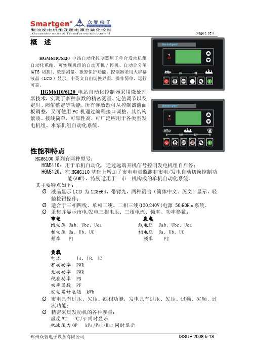
概述HGM6110/6120电站自动化控制器用于单台发动机组自动化系统,可实现机组的自动开机/停机、自动合分闸(A TS切换)、数据测量、报警保护功能。
控制器采用大屏幕液晶(LCD)显示,中英文自由切换界面,操作简单,运行可靠。
HGM6110/6120电站自动化控制器采用微处理器技术,实现了多种参数的精密测量、定值调节以及定时、阈值整定等功能,所有参数既可从控制器前面板调整,又可使用PC机通过编程接口调整。
其结构紧凑、接线简单,可靠性高,可广泛应用于各类型发电机组、水泵机组自动化系统。
性能和特点HGM6100系列有两种型号:HGM6110:用于单机自动化,通过远端开机信号控制发电机组自启停;HGM6120:在HGM6110基础上增加了市电电量监测和市电/发电自动切换控制功能(AMF),特别适用于一市一机构成的单机自动化系统。
其主要特点如下:Ø液晶显示LCD为128x64,带背光,两种语言(简体中文、英文)显示,轻触按钮操作;Ø适合于三相四线、单相二线、二相三线(120/240V)电源50/60Hz系统。
Ø采集并显示市电/发电三相电压、三相电流、频率、功率参数;市电发电线电压 Uab,Ubc,Uca 线电压 Uab,Ubc,Uca相电压 Ua,Ub,UC 相电压 Ua,Ub,UC频率 F1 频率 F2负载电流 IA,IB,IC有功功率 PWR无功功率 PWR视在功率 PS功率因数 PF发电累计电能 kWhØ市电具有过压、欠压、缺相功能,发电具有过压、欠压、过频、欠频、过流功能;Ø精密采集发动机的各种参量:温度WT ℃/℉同时显示机油压力OP kPa/Psi/Bar同时显示燃油位 FL 单位:%转速SPD 单位:RPM电池电压VB 单位:V充电机电压VD 单位:V计时器HC 可累计999999小时累计启动次数最大可累计999999次Ø控制保护功能:实现柴油发电机组自动开机/停机、合分闸(ATS切换) 及完善的故障显示保护等功能;Ø具有得电停机、怠速控制、预热控制功能,且均为继电器输出。
quick焊台322使用手册

quick焊台322使用手册【最新版】目录1.quick 焊台 322 简介2.使用前的准备3.焊接操作步骤4.安全注意事项5.维护与保养正文一、quick 焊台 322 简介quick 焊台 322 是一款性能优越、操作简便的焊台,适用于各种电子焊接作业,如焊接电子元件、电路板等。
它具有稳定的温度控制、高效的热传导以及安全的保护功能,是电子制造、维修等行业的理想选择。
二、使用前的准备1.检查焊台外观是否有破损,确保设备完好无损。
2.将焊台接入电源,并确保电源电压与焊台额定电压相符。
3.接通电源后,打开焊台开关,检查是否正常工作。
4.根据需要准备焊接工具,如烙铁头、焊接锡丝等。
三、焊接操作步骤1.将待焊接的元件或电路板固定在焊接工作台上,确保牢固。
2.选择合适的烙铁头,将其插入焊台烙铁座,并确保连接牢固。
3.打开焊台加热开关,将烙铁头加热至适当的温度。
通常情况下,焊接电子元件时,烙铁头的温度控制在 200-300 摄氏度之间;焊接电路板时,温度控制在 300-400 摄氏度之间。
4.将焊接锡丝放在烙铁头上,使其与烙铁头紧密贴合。
5.将烙铁头接触到待焊接部位,适当施加压力,使锡丝熔化并与元件或电路板焊接牢固。
6.焊接完成后,关闭焊台加热开关,等待烙铁头冷却至室温后,拔掉电源插头。
四、安全注意事项1.使用焊台时,请勿触及烙铁头,以免烫伤。
2.焊接过程中,务必确保烙铁头与焊接部位紧密贴合,以防止焊接不良。
3.避免在潮湿、高温或易燃易爆的环境中使用焊台。
4.如发现焊台异常现象,如发热、冒烟等,请立即停止使用,并联系专业人员进行检修。
五、维护与保养1.使用后,请将焊台清洁干净,避免烙铁头、焊接工作台等部位沾染焊锡或其他污渍。
2.定期检查焊台的工作状态,如有异常,请及时处理。
LED622A用户手册V3.00
LED622ALED可视光强测试仪用户手册LED622AVISUAL LED LUMINOUS INTENSITY METERUSER’S MANUALVer 3.00杭州远方光电信息有限公司EVERFINE PHOTO-E-INFO CO., LTD.地址:杭州市滨江区滨康路669号1号楼(310053)ADD:Bldg.1, #669 Binkang Rd., Binjiang Hi-Tech Zone, Hangzhou(310053), ChinaTel :86-571-86698333Fax :86-571-86696433E-mail:Sales@销售专箱Service@服务专箱http://前言感谢您购置远方LED622A LED可视光强测试仪。
本说明书讲述仪器功能操作说明,为了确保正确使用仪器,在操作仪器前请仔细阅读本说明书。
请妥善保存本说明书,以便遇到问题时快速查阅。
注意:z本说明书内容有可能变动,恕不另外通知,但可保证本说明书与所购仪器一致。
z我们已经尽最大努力准备本说明书,以确保其准确性。
如您有疑问或发现错误,请直接与本公司或本公司授权代理商联系。
z没有本公司书面许可,任何抄袭或改编本手册全部或部分内容均为严重侵权。
z对于本手册内容如有不同理解,以本公司技术部门解释为准。
z用户第一次打开仪器包装箱时,请对照装箱清单,检查仪器和配件,若发现配件不齐或仪器配件不正常,请立即与销售商联系。
目录前言-----------------------------------------------------------------------------------------------------------------------------------1 目录-----------------------------------------------------------------------------------------------------------------------------------2 第1章 概述和基本原理 一概述------------------------------------------------------------------------------------------------------------------------------------------------3 二测量原理------------------------------------------------------------------------------------------------------------------------------------------------3 第2章 仪表功能及技术指标------------------------------------------------------------------------------------------------------------------------------------------------------------------ 5 第3章 仪表面板及按键功能一仪表正面面板-----------------------------------------------------------------------------------------------7 二仪表背面面板-----------------------------------------------------------------------------------------------10 第4章测量、定标、校零与设定一设定---------------------------------------------------------------------------------------------------------------------------12 二测试--------------------------------------------------------------------------------------------------------------------------14 三校零--------------------------------------------------------------------------------------------------------------------15 四光照度定标----------------------------------------------------------------------------------------------------------15 第5章 注意事项------------------------------------------------------------------------------------------------------------------------------------------------------------------------------------------------------ 17第一章 概述和基本原理一、 概述LED 行业在高速发展,LED 应用日趋广泛,对于LED 的电性能及光强的测量,也显得越来越重要,为此,本公司研制了LED622A LED 可视光强测试仪。
it6332a电源说明书

it6332a电源说明书
1、选择同步设置,可以将通道1(CH1)和通道2(CH2),通道2(CH2)和通道3(CH3)或三个通道全部设置为同步模式。
2、选择为同步以后,若改变任一参数,其他通道的对应参数也会成比例改变。
3、例如,先设置CH1和CH2的电压和电流
CH1:4V,1ACH2:8V,2A。
4、将CH1和CH2设置为同步状态,在输出关闭和Meter状态。
产品特点:
1、全隔离三组电压输出,且均可以调节。
2、可选择串、并联或同步使用X1。
3、三路可同时显示电压、电流值
4、½2U小体积
5、面板功能按键背光显示
6、可利用光标调节数字步进值
7、输出有开关控制
8、高分辨率、高精度以及高稳定性
9、远端测量功能,补偿线上压降*2
10、多种保护功能
11、智能温控风扇,降低噪音
12、部分机型内置标准的USB/RS232通讯接口。
DA-662A系列硬件用户手册说明书

DA-662A Series Hardware User’s ManualEdition 2.0, September 2018/product© 2018 Moxa Inc. All rights reserved.DA-662A Series Hardware User’s Manual The software described in this manual is furnished under a license agreement and may be used only in accordance withthe terms of that agreement.Copyright Notice© 2018 Moxa Inc. All rights reserved.TrademarksThe MOXA logo is a registered trademark of Moxa Inc.All other trademarks or registered marks in this manual belong to their respective manufacturers.DisclaimerInformation in this document is subject to change without notice and does not represent a commitment on the part of Moxa.Moxa provides this document as is, without warranty of any kind, either expressed or implied, including, but not limited to, its particular purpose. Moxa reserves the right to make improvements and/or changes to this manual, or to the products and/or the programs described in this manual, at any time.Information provided in this manual is intended to be accurate and reliable. However, Moxa assumes no responsibility for its use, or for any infringements on the rights of third parties that may result from its use.This product might include unintentional technical or typographical errors. Changes are periodically made to the information herein to correct such errors, and these changes are incorporated into new editions of the publication.Technical Support Contact Information/supportMoxa AmericasToll-free: 1-888-669-2872 Tel: +1-714-528-6777 Fax: +1-714-528-6778Moxa China (Shanghai office) Toll-free: 800-820-5036Tel: +86-21-5258-9955 Fax: +86-21-5258-5505Moxa EuropeTel: +49-89-3 70 03 99-0 Fax: +49-89-3 70 03 99-99Moxa Asia-PacificTel: +886-2-8919-1230 Fax: +886-2-8919-1231Moxa IndiaTel: +91-80-4172-9088 Fax: +91-80-4132-1045Table of Contents1.Introduction ...................................................................................................................................... 1-1Overview ........................................................................................................................................... 1-2 Package Checklist ............................................................................................................................... 1-2 Product Features ................................................................................................................................ 1-2 Hardware Specifications ...................................................................................................................... 1-3 2.Hardware Introduction...................................................................................................................... 2-1Appearance ........................................................................................................................................ 2-2 DA-662A-8 ................................................................................................................................. 2-2DA-662A-16 ............................................................................................................................... 2-2 Dimensions ........................................................................................................................................ 2-3 Hardware Block Diagram ..................................................................................................................... 2-3 DA-66A-8 ................................................................................................................................... 2-3DA-662A-16 ............................................................................................................................... 2-4 LED Indicators .................................................................................................................................... 2-4 Reset Button ...................................................................................................................................... 2-4 LCD Screen ........................................................................................................................................ 2-5 Push Buttons ...................................................................................................................................... 2-5 Real-time Clock .................................................................................................................................. 2-5 3.Hardware Connection Description ..................................................................................................... 3-1Placement Options .............................................................................................................................. 3-2 Rack Mounting ............................................................................................................................ 3-2 Connecting the Hardware..................................................................................................................... 3-2 Wiring Requirements ................................................................................................................... 3-2Connecting the Power .................................................................................................................. 3-2Connecting to the Network ........................................................................................................... 3-3Connecting to a Serial Device ....................................................................................................... 3-3Configurable Pull High/Low Resistors for the RS-485 Port ................................................................. 3-4Connecting to the Console Port ..................................................................................................... 3-5USB Host.................................................................................................................................... 3-5CompactFlash ............................................................................................................................. 3-51Introduction The DA-662A series embedded computers come with 8 to 16 software selectable RS-232/422/485 serial ports, making them suitable for a variety of industrial applications. Models are available with 4 10/100 Mbps Ethernet ports. The DA-662A series model also comes with CF and USB ports to make it easy to add additional storage space. The computers are designed with a standard 19-inch, rugged 1U rackmount case, and are embedded with a 100-240 VAC power input. This combination of features gives users a robust and reliable ready-to-run solution for applications such as data acquisition and power substations.The following topics are covered in this chapter:❒Overview❒Package Checklist❒Product Features❒Hardware SpecificationsOverviewThe DA-662A series are RISC-based, ready-to-run embedded computers designed for industrial dataacquisition applications. Each model has 8 or 16 RS-232/422/485 serial ports, and 2 USB hosts based on the Moxa Macro 500 MHz communication processor. The DA-662A series has 4 Ethernet ports. The casing is astandard 1U, 19-inch wide rack-mounted rugged enclosure. The robust, rack-mountable mechanism design provides the hardened protection needed for industrial environment applications, and makes it easy for users to install the DA-662A series on a standard 19-inch rack. The DA-662A series are ideal for applications that require a distributed embedded technology, such as SCADA systems, plant floor automation, and powerelectricity monitoring applications.The DA-662A series are suitable for IT control room applications, the critical assets used in the control andautomation system of industrial plant floors, and in electric power utility substations. The DA-662A series can accept a wide range of power inputs (from 100 to 240V), which means that they can be connected to AC power lines. Because of the no hard disk, fan-less, energy efficient design, the DA-662A series minimize heatgeneration, can operate around the clock, year in and year out, in heavy duty, harsh industrial environments, delivering the kind of reliable computing power expected of a multifunctional controller.Choose from models of the DA-662A series that come pre-installed with the open-standard Linux OS. Thebuilt-in SDK makes program development easy by allowing you to follow the common programmingprocedures used on a standard PC. All of the software you develop for your own applications can be stored in the onboard Flash memory. The DA-662A series embedded computers are ideal for creating control systems with distributed architecture that are based on embedded technologies. Typical applications include SCADAsystems, plant floor automation, and power electricity monitoring.Package ChecklistBefore installing the DA-662A series, verify that the package contains the following items:• 1 DA-662A series embedded computer• 6 jumper caps•19-inch Rackmount Kit with 2 L-shaped metal plates and 8 screws•Ethernet Cable: RJ45-to-RJ45 cross-over cable, 100 cm•CBL-RJ45M9-150: RJ45-to-DB9 male serial port cable, 150 cm•CBL-RJ45F9-150: RJ45-to-DB9 female console port cable, 150 cm•Quick installation guide•Documentation and software CD•Warranty cardNOTE: Notify your sales representative if any of the above items are missing or damaged.Product Features•Moxa Macro 500 MHz Processor•On-board 128 MB RAM, 32 MB Flash ROM•8 to 16 RS-232/422/485 serial ports• 4 10/100 Mbps Ethernet•Standard 19-inch rack-mount installation, 1U height•Wide range of power input voltages from 100 to 240VAC•LCD screen and push buttons for Human-Machine Interface (HMI)•Ready-to-run Linux platform•Robust, fanless designHardware SpecificationsComputerCPU: MoxaMacro 500 MHzOS: Embedded Linux (pre-installed)DRAM: 128 MB onboardFlash: 32 MB onboardEthernet InterfaceLAN: 4 auto-sensing 10/100 Mbps ports (RJ45)Magnetic Isolation Protection: 1.5 kV built-inSerial InterfaceSerial Standards: 8 to 16 RS-232/422/485 ports, software selectable (8-pin RJ45)ESD Protection: 8 kV contact, 15 kV Air ESD protection for all signalsSurge Protection: 2 kV line-to-line and 4 kV line-to-ground surge protection, 8/20 μs waveform(DA-662A-I-8/16-LX only)Insulation: 500 V (DA-662A-I-8/16-LX only)Isolation: 2 kV digital isolation (DA-662A-I-8/16-LX only)Termination Resistor: 120 ohm, jumper selectableConsole Port: RS-232 (all signals), RJ45 connectorSerial Communication ParametersData Bits: 5, 6, 7, 8Stop Bits: 1, 1.5, 2Parity: None, Even, Odd, Space, MarkFlow Control: RTS/CTS, XON/XOFF, ADDC® (automatic data direction control) for RS-485Baudrate: 50 bps to 921.6 Kbps (supports non-standard baudrates; see user’s manual for details)Serial SignalsRS-232: TxD, RxD, DTR, DSR, RTS, CTS, DCD, GND(DA-662A-I-8/16-LX only: TxD, RxD, RTS, CTS, GND)RS-422: TxD+, TxD-, RxD+, RxD-, GNDRS-485-4w: TxD+, TxD-, RxD+, RxD-, GNDRS-485-2w: Data+, Data-, GNDLEDsSystem: OS ReadyLAN: 10/100M x 4Serial: TxD, RxD (8 to 16 of each)Mini Screen with Push ButtonsLCD Panel: Liquid Crystal Display on the case, 2 x 16 text modePush Buttons: Four membrane buttons for convenient on-site configurationPhysical CharacteristicsHousing: SECC sheet metal (1 mm)Weight: 4.3 kgDimensions:Without ears: 440 x 45 x 237 mm (17.32 x 1.77 x 9.33 in)With ears: 480 x 45 x 237 mm (18.90 x 1.77 x 9.33 in)Mounting: Standard 19-inch rackmountEnvironmental LimitsOperating Temperature: -10 to 60°C (14 to 140°F)Storage Temperature: -20 to 70°C (-4 to 158°F)Ambient Relative Humidity: 5 to 95% (non-condensing)Anti-Vibration: 1 g @ IEC-68-2-6, sine wave (resonance search), 5-500 Hz, 1 Oct/min, 1 Cycle, 13 mins 17 sec per axisPower RequirementsInput Voltage: 100 to 240 VAC auto ranging(47 to 63 Hz for AC input)Power Consumption: 20 WStandards and CertificationsSafety: UL 60950-1EMC:EN 55022/24CISPR 22, FCC Part 15B Class AIEC 61000-4-2 ESD: Contact 8 kV; Air 15 kVIEC 61000-4-3 RS: 3 V/m (80 MHz to 1 GHz)IEC 61000-4-4 EFT: Power 1 kV; Signal 0.5 kVIEC 61000-4-5 Surge: Power 2 kV; Signal 4 kVIEC 61000-4-6 CS: 3 VIEC 61000-4-8IEC 61000-4-11Green Product: RoHS, CRoHS, WEEEReliabilityAlert Tools: Built-in buzzer and RTC (real-time clock) Automatic Reboot Trigger: Built-in WDT (watchdog timer) MTBF (mean time between failures): 125,733 hrs WarrantyWarranty Period: 5 yearsDetails: See /warranty2Hardware Introduction DA-662A series hardware is compact, well-designed, and built rugged for industrial applications. LED indicators help you monitor the performance and identify trouble spots. Multiple ports allow the connection of different devices for wireless operation. With the reliable and stable hardware platform that is provided, you may devote your attention to the development of your application. In this chapter, learn the basics about the embedded computer hardware and its different parts.The following topics are covered in this chapter:❒AppearanceDA-662A-8DA-662A-16❒Dimensions❒Hardware Block DiagramDA-66A-8DA-662A-16❒LED Indicators❒Reset Button❒LCD Screen❒Push Buttons❒Real-time ClockAppearance DA-662A-8Front ViewRear ViewDA-662A-16Front ViewRear ViewDimensionsHardware Block DiagramThe following block diagrams show the layout of the DA-662A series’ internal components. DA-66A-8DA-662A-16LED IndicatorsLED indicators are located on the front panel of the DA-662A series. LED Name LED Color LED FunctionReady Red Power is On, and system is ready (after booting up) LAN1, LAN2, LAN3, LAN4 Orange10 Mbps Ethernet connection Green 100 Mbps Ethernet connectionP1-P16 (Rx) Orange Serial port is receiving RX data from the serial device Off Serial port is not receiving RX data from the serial device P1-P16 (Tx)Green Serial port is transmitting TX data to the serial device OffSerial port is transmitting TX data to the serial deviceReset ButtonPress the Reset button on the front panel continuously for at least 5 seconds to load the factory default configuration . After the factory default configuration has been loaded, the system will reboot automatically. The Ready LED will blink on and off for the first 5 seconds, and then maintain a steady glow once the system has rebooted.We recommend that you only use this function if the software is not working properly and you want to load factory default settings. To reset an embedded Linux system, always use the software reboot command />reboot to protect the integrity of data being transmitted or processed. The Reset button is not designed to hard reboot the DA-662A series.LCD ScreenThe DA-662A series has an LCD screen on the front panel. The LCD screen can display 16 columns and 2 rows of text. After the DA-662A series boots up, the LCD screen will display the model name and firmware version:D A - 6 6 2 A - 1 6 VER.1.Push ButtonsThere are four push buttons on the DA-662A series’ front panel. The buttons are used to enter text onto the LCD screen. The buttons are MENU, (up cursor),(down cursor), and SEL:Button ActionMENU Displays the main menu.Scrolls up through a list of items shown on the LCD screen’s second line.Scrolls down through a list of items shown on the LCD screen’s second line. SELSelects the option listed on the LCD screen.Real-time ClockThe DA-662A series’ real time clock is powered by a lithium battery. We strongly recommend that you do not replace the lithium battery without help from a qualified Moxa support engineer. If you need to change the battery, contact the Moxa RMA service team.3 Hardware Connection DescriptionThe following topics are covered in this chapter:❒Placement OptionsRack Mounting❒Connecting the HardwareWiring RequirementsConnecting the PowerConnecting to the NetworkConnecting to a Serial DeviceConfigurable Pull High/Low Resistors for the RS-485 PortConnecting to the Console PortUSB HostCompactFlashPlacement OptionsRack MountingThe DA-662A series is designed to be mounted on a standard 19-inch rack. Two L-shaped metal plates areincluded as standard accessories with the DA-662A series. Use the enclosed pair of L-shaped metal plates and screws to fasten your DA-662A series to the rack cabinet. Two placement options are available. You can either lock the front or the rear panel of the DA-662A series to the front of the rack. Each L-shaped plate has 6 holes, leaving two outer or inner holes open for your convenience.Connecting the HardwareThis section describes how to connect the DA-662A series to serial devices. The topics covered in this section are: Wiring Requirements, Connecting the Power, Connecting to the Network, Connecting to aSerial Device, and Connecting to the Console Port.Wiring RequirementsYou should observe the following common wiring rules:•Use separate paths to route wiring for power and devices. If power wiring and device wiring paths must cross, make sure the wires are perpendicular at the intersection point.NOTE: Do not run signal or communication wiring and power wiring in the same wire conduit. To avoidinterference, wires with different signal characteristics should be routed separately.•You can use the type of signal transmitted through a wire to determine which wires should be kept separate.The rule of thumb is that wiring that shares similar electrical characteristics can be bundled together.•Keep input wiring and output wiring separate.•Where necessary, it is strongly advised that you label wiring to all devices in the system. Connecting the PowerTo power on the DA-662A series, use a power cord to connect the power line to the DA-662A series’ AC power connector. The power connector is located on the right side of the rear panel. Next, turn on the power switch.The DA-662A series takes about 30 seconds to boot up. Once the device is ready, the Ready LED on the front panel will light up, and the DA-662A series model name and firmware version will appear on the LCD screen.Connecting to the NetworkFor DA-662A series, connect one end of the Ethernet cable to one of the DA-662A series’ 10/100M Ethernet ports (8-pin RJ45) and the other end of the cable to the Ethernet network. If the cable is properly connected, the DA-662A series will indicate a valid connection to the Ethernet in the following ways:Pin Signal 1 ETx+ 2 ETx- 3 ERx+ 4 – 5 – 6 ERx- 7 – 8–Connecting to a Serial DeviceUse properly wired serial cables to connect the DA-662A series to serial devices. The DA-662A series’ serial ports (P1 to P16) use 8-pin RJ45 connectors. The ports can be configured by software for RS-232, RS-422, or 2-wire RS-485. The pin assignments are shown in the following table:PinRS-232 RS-232(DA-662A-I-8/16-LX only)RS-422RS-4851 DSR – – –2 RTS RTS TXD+ –3 GND GND GND GND4 TXD TXD TXD- –5 RXD RXD RXD+ Data+6 DCD – RXD- Data-7 CTS CTS – – 8DTR–––Configurable Pull High/Low Resistors for the RS-485 PortIn some critical environments, you may need to add termination resistors to prevent the reflection of serialsignals. When using termination resistors, it is important to set the pull high/low resistors correctly so that the electrical signal is not corrupted. The DA-662A series uses jumper settings to set the termination resistors and pull high/low resistor values for each serial port.To configure the termination or pull high/low resistors, you first need to open the DA-662A's chassis. You will see 3 rows of jumper caps (as shown in the accompanying figure). The first row is for setting pull high resistors, the second row is for setting termination resistors, and the third row is for setting pull low resistors.Each serial port has 6 jumper caps for configuring the resistors. The pin assignments are shown in the following table:Jumper settingRS485 Data + RS485 Data -Pull High resistors1-2: 150 kΩ2-3: 1 kΩTermination1-2: Open2-3: 120 ΩPull Low resistors1-2: 150 kΩ2-3: 1 kΩTo set the termination resistors to 120 Ω, make sure that PIN 2 and PIN 3 assigned to the serial port are shorted by jumper caps.To set the pull high/low resistors to 150 kΩ, make sure that PIN 1 and PIN 2 assigned to the serial port are shorted by jumper caps. This is the default setting.To set the pull high/low resistors to 1 kΩ, make sure that PIN 2 and PIN 3 assigned to the serial port are shorted by jumper caps.Connecting to the Console PortThe DA-662A series’ console port is an 8-pin RJ45 RS-232 port. The pin definition is the same as for the serial ports (P1 to P16).USB HostThe DA-662A series offers 2 USB 2.0 hosts, allowing you to connect with a USB storage device. The first USB mass storage device to be connected will be mounted automatically by mount to /mnt/sdc, and the second device will be mounted automatically to /mnt/sdd. The DA-662A series will be un-mounted automatically with the umount command when the device is disconnected.CompactFlashThe DA-662A series have a built-in CompactFlash socket. The CompactFlash socket allows users to addadditional memory by inserting a CompactFlash memory card, without any risk to the computer.Follow the instructions below to insert a CompactFlash card:1.Turn off DA-662A.2.Insert the CompactFlash card into the socket.3.Turn on DA-662A.。
第2章 GF622系列光纤传输设备
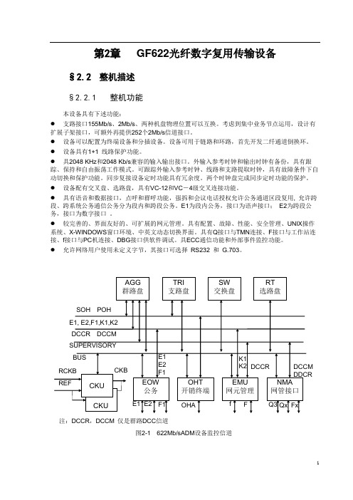
第2章GF622光纤数字复用传输设备§2.2 整机描述§2.2.1 整机功能本设备具有下述功能:●支路接口155Mb/s、2Mb/s、两种机盘物理位置可以互换。
考虑到集中业务节点运用,设计有扩展子架接口,可额外再提供252个2Mb/s信道接口。
●设备可以配置为终端设备和分插设备。
设备可用于链路和环路,首先开发二纤通道倒换环。
●设备具有1+1 线路保护功能。
●具2048 KHz和2048 Kb/s兼容的输入输出接口。
外输入参考时钟和输出时钟有备份,具有跟踪、保持和自由振荡工作模式。
可跟踪外输入参考时钟、线路和支路提取时钟,具有故障条件下自动切换和保护功能。
同步复接设备定时功能具有冗余度。
两个时钟盘完成同步定时功能的保护。
●设备配有交叉盘、选路盘,具有VC-12和VC-4级交叉连接功能。
●具有语音和数据接口,点呼和群呼功能,强拆和会议电话授权允许公务通道区段复用, 允许跨段、跨系统公务通信公务分为段内和跨段公务。
E1为段内公务,接口为语声接口;E2为跨段公务,接口为数字接口。
●较完善的、界面友好的、可扩展的网元管理。
具有配置、故障、性能、安全管理、UNIX操作系统、X-WINDOWS窗口环境、中英文动态切换界面。
具有Q接口与TMN连接、F接口与工作站连接、f接口与PC机连接、DBG接口供软件调试。
具ECC通信功能和外部事件监控功能。
●允许网络用户使用未定义字节,其接口可选择RS232 和G.703。
注:DCCR,DCCM 仅是群路DCC信道图2-1 622Mb/sADM设备监控信道3§2.2.2 整机方框图本设备由主信道,维护管理通道和时钟等三大部分组成。
主信道传输电信业务信号。
维护管理部分提供管理通信接口,公务联络,开销处理功能等。
设备的总体框图见图2-1所示。
主信道包括群路盘、交叉盘、选路盘和支路盘。
维护管理部分包括网管接口,公务盘,网元管理盘开销终端盘。
时钟部分包括时钟盘。
优利德 UDP6722 可编程直流电源 说明书
UDP6722可编程直流电源
数据手册
REV 0
2023.04
⏹80V/20A/400W功率输出;
⏹采用4.3寸 TFT-LCD显示,简洁面板操作;
⏹高精度低纹波;
⏹过压、过流、过温保护
⏹远端补偿功能;
⏹列表、延时器功能,模拟多种带载情况;
⏹电压电流功率波形显示
⏹风扇智能调节;
⏹丰富的接口:RS232、RS485、LAN、USBHost、USBDevice;
⏹支持SCPI/MODBUS协议;
UDP6722可编程直流电源是一款宽范围开关电源。
该机型具有体积小、重量轻功能强大的特性;采用液晶屏,参数直观,操作快捷;可应用于自动化测试系统、产品研发调试、实验室、教学实验、手机家电维修等领域。
波形显示
可以显示电压电流功率的波形,当设置或者输出变动时,能够非常直观的显示出来。
列表功能
列表模式提供最多200步的序列输出,每一步都可以自定义电压电流和输出时间,以适应各种输出需求,输出结束后可以列表循环也可以终止循环。
延时器功能
延时器模式提供最多200步的序列输出,和列表模式相比,只有输出和不输出两种状态,输出参数就当前设置参数,简化了用户设置。
额定输出电压额定输出电流输出功率
负载调节率
UNI-T技术支持热线: 400-876-7822
是优利德科技(中国)股份有限公司的英文名称和商标。
本文档中的产品信息可不经通知而变更,有关UNI-T最新的产品、应用、服务等方面的信息,请访问UNI-T官方网址
版权所有仿冒必究。
艾德克斯电子 三路可编程直流电源IT6322 说明书
用户使用手册三路可编程直流电源型号IT6322© 版权归属于艾德克斯电子(南京)有限公司 Ver1.0/Aug, 2005/ IT6300-508第一章快速入门 (6)1.1前面板及后面板描述 (6)前面板布局 (6)后面板布局 (7)1.2初步检查 (7)1. 检查供应清单 (7)2.接上电源线并打开电源 (7)3.系统自检 (7)4.输出检查 (9)5.如果开启电源开关,但不能显示 (9)6.电源保险丝的更换方法 (10)7.电源供应器把柄的调节方法 (10)第二章技术规格 (11)2.1主要技术参数 (11)2.2补充特性 (12)第三章面板操作 (12)3.1前面板操作介绍 (12)3.2键盘安排 (13)3.3VFD标记描述及三路同时输出接线图 (13)VFD标记描述 (13)三路同时输出接线图 (14)3.4菜单描述 (14)3.5面板操作 (15) 通道操作 (15) OUT ON/OFF输出设定 (15) 定时器操作 (16) 电压操作 (16) 电流操作 (17) 数据保存/读取设置 (17) 过热保护 (17)3.6菜单功能描述 (18)第四章电源与PC间的通讯 (21)4.1通讯模块简介 (21)4.2电源与PC间的通讯 (22)4.3SCPI命令表 (23)4.3.1 IEEE488.2共同命令 (23)4.3.2 SCPI标准命令 (23)4.4SCPI命令描述 (25)4.4.1 SCPI状态寄存器 (25)4.4.2 SCPI解释 (28)第五章 PV6300软件使用说明 (37)5.1系统简介 (37)5.2系统安装 (37)5.3PV6300软件功能介绍 (37)5.3.1 保存和读取功能 (39)5.3.2 电压/电流波形图说明 (39)5.3.3 状态栏 (39)5.4基本操作 (40)5.4.1 设置系统参数 (40)5.4.2 设置电压/电流值 (40)5.5快速设置 (41)5.5.1 Hotkey (41)5.5.2电压扫描(VoltageSweep) (41)5.5.3 编程设置 (42)5.5.4 自动测试功能(GO/NG) (42)IT6322直流可编程电源供应器安全请勿自行在仪器上安装替代零件,或执行任何未经授权的修改。
quick焊台322使用手册
quick焊台322使用手册(原创实用版)目录1.Quick 焊台 322 简介2.Quick 焊台 322 的主要功能与特点3.Quick 焊台 322 的使用方法4.Quick 焊台 322 的维护与保养5.安全注意事项正文一、Quick 焊台 322 简介Quick 焊台 322 是一款性能优越、操作简便的焊接设备,适用于各种电子焊接作业,如焊接电子元件、电路板等。
凭借其稳定的性能和易用的操作方式,Quick 焊台 322 在电子制造、维修、研发等领域具有广泛的应用。
二、Quick 焊台 322 的主要功能与特点1.稳定的焊接性能:Quick 焊台 322 采用先进的焊接技术,能够确保焊接质量,提高焊接效率。
2.多功能操作:设备支持多种焊接模式,满足不同焊接需求。
3.高精度温度控制:Quick 焊台 322 具有高精度温度控制系统,能够实现精确的温度控制,确保焊接质量。
4.易于操作:设备操作简便,上手快,即使是初学者也能快速掌握。
三、Quick 焊台 322 的使用方法1.开机准备:确保设备及工作环境清洁,接通电源,打开设备开关。
2.设定焊接参数:根据焊接需求,设置焊接温度、时间等参数。
3.安装焊接电极:选择合适的焊接电极,安装到设备上。
4.焊接操作:将待焊接元件放置在工作台上,启动设备,进行焊接。
5.关闭设备:焊接完成后,关闭设备,切断电源。
四、Quick 焊台 322 的维护与保养1.定期清洁设备,保持工作环境整洁。
2.检查焊接电极,如有磨损及时更换。
3.定期校准温度控制系统,确保温度准确。
4.避免设备长时间空载运行,以免损坏设备。
五、安全注意事项1.使用设备时,务必确保手部干燥,以免触电。
2.非专业人员不得拆卸设备,以免造成损坏。
3.设备工作时,切勿触摸发热部分,以免烫伤。
第1页共1页。
优利德 UDP6722 可编程直流电源 说明书
UDP6722可编程直流电源用户手册REV 02023.05尊敬的用户:您好!感谢您选购全新的优利德仪器,为了正确使用本仪器,请您在本仪器使用之前仔细阅读本说明书全文,特别有关“安全注意事项”的部分。
如果您已经阅读完本说明书全文,建议您将此说明书进行妥善的保管,与仪器一同放置或者放在您随时可以查阅的地方,以便在将来的使用过程中进行查阅。
优利德科技(中国)股份有限公司版权所有。
如果原购买者自购买该产品之日起三年内,将该产品出售或转让给第三方,则保修期应为自原购买者从UNI-T或授权的UNI-T分销商购买该产品之日起三年内。
探头及其他附件和保险丝等不受此保证的保护。
如果在适用的保修期内证明产品有缺陷,UNI-T可自行决定是修复有缺陷的产品且不收部件和人工费用,或用同等产品(由UNI-T决定)更换有缺陷的产品。
UNI-T作保修用途的部件、模块和更换产品可能是全新的,或者经修理具有相当于新产品的性能。
所有更换的部件、模块和产品将成为UNI-T的财产。
以下提到的“客户”是指据声明本保证所规定权利的个人或实体。
为获得本保证承诺的服务,“客户”必须在适用的保修期内向UNI-T通报缺陷,并为服务的履行做适当安排。
客户应负责将有缺陷的产品装箱并运送到UNI-T指定的维修中心,同时预付运费并提供原购买者的购买证明副本。
如果产品要运送到UNI-T维修中心所在国范围内的地点,UNI-T应支付向客户送返产品的费用。
如果产品送返到任何其他地点,客户应负责支付所有的运费、关税、税金及任何其他费用。
本保证不适用于由于意外、机器部件的正常磨损、在产品规定的范围之外使用或使用不当或者维护保养不当或不足而造成的任何缺陷、故障或损坏。
UNI-T根据本保证的规定无义务提供以下服务:a) 修理由非UNI-T服务代表人员对产品进行安装、修理或维护所导致的损坏;b) 修理由于使用不当或与不兼容的设备连接造成的损坏;c) 修理由于使用不符合本说明书要求的电源而造成的任何损坏或故障;d) 维修已改动或者与其他产品集成的产品(如果这种改动或集成会增加产品维修的时间或难度)。
- 1、下载文档前请自行甄别文档内容的完整性,平台不提供额外的编辑、内容补充、找答案等附加服务。
- 2、"仅部分预览"的文档,不可在线预览部分如存在完整性等问题,可反馈申请退款(可完整预览的文档不适用该条件!)。
- 3、如文档侵犯您的权益,请联系客服反馈,我们会尽快为您处理(人工客服工作时间:9:00-18:30)。
1)在安装或使用本产品前,使用者必须详细阅读本操作手册。
2)本产品须由受过正确训练的人员来安装或操作。
安装作业时必须关闭所有电源,切记不
3)
害。
4)为安全起见,禁止以延长线作电源座供应二项以上的电器产品使用。
5)在连接电源线时,必须确定工作电压低于AC 250V,且符合本产品标识中规定的额定电压值。
※注意:电控箱电源规格如为AC220V时,请勿插接至AC380V的电源插座上,否则将出现异常且电机无法动作。
此时请立即关闭电源开关,重新检查电源。
持续供应380V超过五分钟以上,将可能烧损电控箱内器件,而危及人身安全。
6)请不要在日光直接照射的场所、室外及室温45℃以上或0℃以下的场所操作。
7)请不要在暖气(电热器)旁、有露水的场所及在相对湿度10%以下或90%以上的场所操作。
8)请不要在灰尘多的场所、具有腐蚀性物质的场所及有挥发性气体的场所操作。
9)请注意所有电源线、信号线、接地线等接线时不要受压或过度扭曲,以确保使用安全。
10)电源线的接地端须以适当大小的导线和接头连接到生产工厂的系统地线,此连接必须被永久固定。
11)所有可转动的部分,必须以所提供的零件加以防范露出。
12)在安装完成第一次开电后,先关闭切线功能以低速操作缝纫机并检查转动方向是否正确、运转是否稳定。
13)在进行以下操作前,请先关闭所有电源:
1.在控制箱与马达上插拔任何连接插头时。
2.穿针线时。
3.翻抬缝纫机机头时。
4.修理或做任何机械上的调整时。
5.机器闲置不用时。
14)修理或高层次的保养工作,仅能由受过训练的机电技师来执行。
所有维修用的零件,须由本公司提供认可,方可使用。
15)使用本产品请远离高频电磁波和电波发射器等,以免所产生的电磁波干扰伺服驱动装置而发生误动作。
16)请不要以不适当物体来敲击或撞击本产品及各装置。
保修期限
本产品保修期限为购买日期起一年内或出厂月份起两年内。
保修内容
本产品在正常情况使用且无人为操作失误的前提下,于保修期间无偿为客户维修使能正常操作。
但以下情况于保修期间将收取维修费用:
1.不当使用包括误接高压电源、将产品移做其它用途、自行拆卸、维修、更改、或不依
规格范围使用、进水进油及插入异物于本产品。
2.火灾、地震、闪电、风灾、水灾、盐蚀、潮湿、异常电压及其它天灾或不当场所造成
的损害。
3.客户购买后摔落本产品,或客户自行运输(或托付运输公司)造成的损害。
* 本产品在生产及测试上皆尽最大努力和严格控制使其达到高品质及高稳定的标准,但外部的电磁或静电干扰或不稳定的供应电源,仍可能对本产品造成影响或损害,因此操作场所的接地系统一定要确实做好,并建议用户安装故障安全防护装置(如漏电保护器)
1.按键显示及操作说明
1.1按键说明
名称按键注明
起始回缝键执行起始回缝B段或执行起始回缝(A、B段)1次执行起始回缝(A、B段)2次
终止回缝键执行终止回缝C段或执行终止回缝(C、D段)1次执行终止回缝(C、D段)2次
连续回缝键连续回缝功能设定。
自由缝键一旦踏板往前踏下就正常车缝,当踏板回到中立时,立即停止车缝。
当踏板往后踏时,就自动完成切线/ 扫线等动作。
一段定针缝键执行E段定针缝
多段定针缝键连续按键,将循环切换四段缝、七段缝、八段缝、自定义十五段缝模式,显示屏显示相应图标。
自动触发键(只在定针缝中有效)当触发功能打开时,显示屏显示图标。
触发脚踏板,自动走完设定的缝纫过程。
切线开关设定使用或取消切线功能。
夹线开关
设定使用或取消夹线功能。
自动抬压脚设定键1、图标亮时,切完线后压脚自动抬起。
2、图标亮时,车缝中马达停止时压脚自动抬起。
3、2个图标都亮时,切完线后和车缝中马达停止时压脚都自动抬起。
4、当2图标都不亮时,无自动抬压脚功能。
停针位置选择键1:图标亮表示停车时在上停针位2:图标亮表示停车时在下停针位
慢速起缝键
设定使用或取消慢速起缝功能。
补针键车缝中途停止时,按一下则作提针或往前补半针。
功能参数编辑
键
进入或退出功能参数的编辑。
参数查看保存键对所选参数号内容进行查看和保存:选择好参数号后按此键可以进行查看和修改操作,修改参数值后按此键则退出并保存参数。
参数递增键增大参数
参数递减键减小参数
加速键加速键提高运行速度减速键降低运行速度
1.2 手动调整定位
1.3 恢复出厂设置
1.4 电机电角度校正
按住补针键,同时开启电源,屏幕显示“P-92”,按S 键进入参数项,再按补针键,然后电机会自动运转并计算电机电角度,等电机停下来后,参数值将自动变化,按S 键保存即可。
1.5 计数器显示
在一般缝纫模式下,长按切线开关键,显示屏将显示计数器界面。
每一次缝纫周期结束,记为完成一件加工件。
1.6 保存参数值为初始值
在参数值界面,长按慢速起缝键,显示屏将显示“SA VE ”1秒,再按S 键确认。
从此以后,每次恢复出厂设置时,参数值将恢复为保存后的参数值。
2.参数表
注:参数初始值仅供参考,实际参数值以实物为准。
3.错误代码表
E11
复正常后重启系统。
若仍不能正常工作,请更换电机并通知售后服务。
E14
编码器信号异常
关闭系统电源,检查电机编码器接口是否松动或脱落,将其恢复正常后重启系统。
若仍不能正常工作,请更换电机并通知售后服务。
E15 电力模块不正常过流保护 关闭系统电源,再重新开启。
若仍不能正常工作,请更换控制箱并通知售后服务。
E17
机头保护开关没到正确位置
关闭系统电源,检查机头是否掀开,控制箱内滚珠开关是否移位或损坏。
E20 电机启动失败(电角度错误)
关闭系统电源,检查电机编码器接口和电机电源接口是否松动或脱落,将其恢复正常后重启系统。
若仍不能正常工作,请更换控制箱并通知售后服务。
oil 油量过低
关闭电源,检查缝纫机油量是否过低,将油量加满后重启系统。
若仍不能正常工作,请更换油位感应器并通知售后服务。
4. 端口示意图 4.1 端口说明
脚踏板接插端口抬压脚接插端口
机头14P 功能端口~220V 电源线
4.2 14P 功能端口说明
1.剪线电磁铁:1、8(+32V )
2.夹线(扫线)电磁铁:2、9(+32V )
3.松线电磁铁:3、10(+32V )
4.LED 灯:4(DGND )、11(+5V )
5.倒缝按键:5(信号)、12(DGND )
6.倒缝电磁铁:6、13(+32V )
7.补针按键:7(信号)、14(DGND )。