TI 天线选择
一种新型三线式宽频带短波基站天线
[ 1 ] 朱 丽 , 娄国伟 , 李兴国 ,等. 55 GHz毫米波传播特性 及应用 [ C ] / /全国微波毫米波会议 ,成都 : 中国电子学 会 , 2001.
[ 2 ] Ihara T, Fujimura K. Research and development trends of m illimeter2wave short range app lication system s[ J ]. IE ICE Trans. Commun, 1996, 16 (12) : 1741 - 1753.
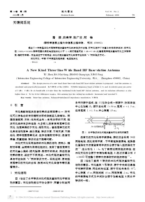
= 300Ω 可在整个频带内获得较好的驻波特性 [ 2 ] 。 图 2给出了呈倒 V 架设的三线式短波基站天线
结构示意图 。天线呈倒 V 形架设 ,振子中央部位悬挂 于支撑杆顶端 ,两边斜向拉直 ,振子对地夹角约 55°。 中心架高 15 m ,两侧间距 18 m ,两侧架高 2 m。天线 的平衡馈电方式及中间折合振子加载电阻 R 同水平 架设时一致 。
Vol. 30 No. 2
Modern Radar
February 2008
79
天馈伺系统
一种新型三线式宽频带短波基站天线 3
屠 振 ,白贵芳 ,张广求 ,邢 锋
(解放军信息工程大学信息工程学院 , 郑州 450002)
【摘要 】 提出了一种新型三线式宽频带短波基站天线的详细设计过程 ,对天线进行了仿真分析和实际测试 ,该天线 在 2 MHz~30 MHz频带范围内满足电压驻波比小于 2. 0,相对增益可达 3 dB i~5 dB i,比普通宽带短波基站天线工作频带 宽 、辐射效率高 。而且适应于不同用途 ,三线式短波基站天线具有平拉和倒‘V ’两种架设方式 。
【关键词 】 三线天线 ; 平衡 2不平衡阻抗变换器 ; 电压驻波比 中图分类号 : TN822 文献标识码 : A
ti 无线充电方案
无线充电方案简介无线充电技术是一种通过电磁感应或者电磁辐射的方式将电能传输到被充电设备的充电方式。
它摆脱了传统有线充电需要插拔的限制,给用户带来了更加方便的充电体验。
本文将介绍几种常见的无线充电方案,并对它们进行比较。
感应式无线充电感应式无线充电是目前应用最广泛的无线充电技术之一。
它利用两个线圈之间的电磁感应原理实现充电。
其中,发送端将电能变为高频交流电信号,并通过电磁感应线圈将信号传输给接收端。
接收端的电磁感应线圈将接收到的信号转换为直流电能,用于充电。
优点:•充电效率高,可以达到有线充电的水平;•具有较好的兼容性,适用于多种设备;•充电过程中无需插拔,方便快捷。
缺点:•充电距离受限,一般为几厘米至几十厘米之间;•对充电设备的位置和摆放情况要求较高,需要保持发送端和接收端的对齐。
辐射式无线充电辐射式无线充电是一种将电能通过辐射介质(如空气)传输到被充电设备的充电方式。
它利用电磁波的传播特性实现充电。
发送端会将电能转化为高频电磁波,并通过发送天线将电磁波辐射出去。
接收端的天线会接收到电磁波,并将其转换为直流电能,用于充电。
优点:•充电距离较远,可以实现室内多点充电;•具有强大的穿透力,不受障碍物的限制;•具备一定的定向性,可以减少能量的浪费。
缺点:•充电效率较感应式无线充电低;•对充电设备的功率管理要求较高,需要平衡充电速度和稳定性。
光纤式无线充电光纤式无线充电是一种将光能转化为电能并传输到被充电设备的充电方式。
它利用光纤的传输特性实现充电。
发送端会将电能转化为光能,并通过光纤将光能传输到接收端。
接收端的光能转换装置会将光能转化为直流电能,用于充电。
优点:•充电效率高,损耗小,几乎没有电能的损耗;•具有较远的充电距离,几十米至几百米不等;•不受电磁干扰的影响,稳定性较高。
缺点:•光纤成本较高,会增加系统的整体成本;•光纤易受到弯曲和损坏的影响,需要进行维护和保养。
比较和选择不同的无线充电方案各有优劣,需要根据具体的需求和应用场景来选择。
基于MIMO-OFDM子系统的天线选择方法
摘
要 :在 频率选择 性衰 落环境 中,M MO O D 系统能 够极 大地提 高无线通信 系统的容 量和 可 I —F M
靠性。发身 接收天线选择方法能以很 小的性能损失换取射频成本的大幅度降低 ,使 系统不完全 受射 频成本 的 限制 。容量性 能是 天 线 选择 当 中的 重要 准 则 。现提 出一种 基 于子 系统的接 收天 线
Absr t Mu t l n u l p e o tuto t g n lfe u nc v so lilx n y tmsc I g e t tac : li e i p tmu t l up —rho o a r q e y diiin mu t e i g s se a1 r a y p i p l
选择 方法 ,降低 了 多载波 系统 的复 杂度 。仿 真 结果 表 明 , 系统 的 容量 性 能 与传 统方 法相 当,在
接收信 噪 比为 2 d 、发射端采 用 两根接 收 天线的 时候 ,l 2比无 选择 的情 况得 到近 12比特/ 0B 2选 .
信道 的容量 增量 ,并且 容量增 益随着 天线的增加 而增加 。
Th r n miso /r c ii g a tn a s l cin meh d c n s bsa tal e u e he e ta s si n e e vn ne n ee to to a u tn ily r d c t RF c s t it o twi a l l h te s se y tm p ro ma c l s e fr n e o s, t s lmi a e he i t f hu ei n t t l o RF c s t MI mi ot o MO— OFDM s se y tm. Ca a i p ct y p ro a e i mp ra ti n e n e e t n e r nc s i o t n n a tn a s lc o .A o e n e n ee to lo i m a e n s b-y tm fm i n v la tn a s lcin a g rt h b s d o u s se i r p s d wh c d c e s s t e o u a o l o l xt i mu t—a re s se s p o e i h e r a e h c mp t t na c mp e iy n o i l c ri r y tm. S mu a in e u t i i lto r s ls i d c t ha he c p ct e o ma c s r u h y s me t he ta i o a t o S Whe te SNR s n i ae t tt a a i p r r n e i o g l a o t r dt n lmeh d’ . y f i nh i 2 dB a d ta s te s st n e n s h e o a c ft n e n ss lce r m 2 a tn a an 0 n r n mitru e woa tn a ,t e p r r n e o f m woa tn a ee td fo 1 e n sg i s n 1 5 /s . b /Hz t a a fn ee t n c s .T e c pa i an i r a e t h n e n ua t y n t to o s lc i a e h a ct g i nce s swi te a tn a q n i . h h o y h t Ke r s: a t n a s lc in;c a n lc p ct y wo d n e n ee t o h n e a a i y;MI MO— OFDM ;s b—y t m u s se
环型天线设计

L A = μ0 A ln
8A B
-2
环型导体电感 L I (单位为 H) :
天线的效率 :
LI
=
μ0
S 2A
η=
RR
RR + RL
+
RX
=
QRR 2πf 0 ( L A + L I)
另外 ,天线的 Q 值必须与用来调谐天线到正确频率
的电容相匹配 。环型天线的 Q 值可以根据下式来选择 :
R FID 系 统 中 的 P C B 环 型 天 线 设 计
■江苏技术师范学院 刘舒祺 牟志刚
摘 要 关键词
本文实现了 RFID 系统中的一种 PCB 环型天线设计 。在对天线的工作原理进行分析的基础上 ,提出基于 13 . 56 M Hz 、200 mW 的低功率阅读器的天线设计方法 ,并给出天线的设计和调试过程 。
环型天线的输入阻抗必须确定 ;同样 ,为了评估天线效率
和辐射阻抗 ,环型导体内的欧姆损耗和其他欧姆损耗也必
须确定下来 。在发射模式下 ,环型天线输入阻抗的等效电
路如图 3 所示[4] 。
环型天线输入阻抗 ZIN 可由下式给出 :
ZIN = ( RR + RL + RX) + j2πf 0 ( L A + L I)
PCB 环型天线 设计 RFID 调试
引 言
天线是一种转能器 。发射时 ,它把发射机的高频电流 转化为空间电磁波 ;接收时 ,它又把从空间截获的电磁波 转换为高频电流送入接收机 。对于设计一个应用于射频 识别系统中的小功率 、短距离无线收发设备 ,天线设计是 其中的重要部分 。良好的天线系统可以使通信距离达到 最佳状态 。天线的种类很多 ,不同的应用需要不同的天 线 。在小功率 、短距离的 RFID 系统中 ,需要一个通信可 靠 、价格低廉的天线系统 , PCB 环型天线是比较常用的 一种 。
STBC-VBLAST系统发射天线选择算法研究
中 图 分 类 号 : N9 12 T 1.1
文献标识码 : A
文章 编 号 :0 7 2 4 2 1 )2 0 1 —0 10 —3 6 (0 10 — 0 3 4
MI MO 系统 既 可 以提 供 空 问 复 用 增 益 又 可 以
获得 复 用 增 益 , 来 受 到广 泛 关 注[ 。。有 的学 者 近 8。 提 出 了基 于 V- L T子 系统容 量最 大准 则 进行 发 B AS 射 天线 选择 [ 在 S C和 V B T都 采 用 相 同 1 ¨, TB -I AS 调制 方 式 的前 提 下 可 以获 得 最 大 系统 容 量 , 是会 但
1 混 合 编 码 系统模 型
SB T C与 V-I T混 合 编 码 系 统 结 构 如 图 1 B AS 所示 。在 发射 天 线 中选 择 一 部 分 进 行 S B 余 下 T C,
则 采用 V B AS - L T。 本文 只 考虑 4发 4收 系统 , 设选 择 发 射 天线 假
2 1 年 3月 01 第 1卷 第 2 6 期
西 安 邮 电 学 院 学 报 JU O RNAL O ’ F XIAN UNI R I O T ND T L C VE STY OFP S S A E E 0M ^ 『 C T1 S 仉 NI A 0N
Ma.2 1 r 01 、 . 6N . 11 o 2
使得 S B T C的性 能受 到影 响 。
提供 空 间分集增 益口 。空 间复用依 赖 于存 在 丰 富散 ]
射体 的 MI MO信 道和 接收端 的信号 处理 , 生多 个 产 并行 的独 立传 输信 道 , 频 谱 效 率 随着 发 射 天 线 和 使
接收 天线 数 目较小 者 线 性 增 长 , 得 所 谓 的复 用 增 获
网络分析仪的使用以及天线匹配
Smith Chart原理
a • 从2.14这个方程可以看出,其是在复平面(Γr, Γi)上、 m 圆的参数方程(x-a)2 + (y-b)²= R²,它以(r/r+1, Bos 0)为圆心,半径为1/1+r.
or 圆周上的点表示具有相同实部的阻 F 抗。例如,r = 1的圆,以(0.5, 0)为 l 圆心,半径为0.5。它包含了代表反 a 射零点的原点(0, 0) (负载与特性阻抗 ti 相匹配)。以(0, 0)为圆心、半径为1 n 的圆代表负载短路。负载开路时,圆 e 退化为一个点(以1, 0为圆心,半径为 id 零)。与此对应的是最大的反射系数1 f ,即所有的入射波都被反射回来。所 Con 有的圆心都在X轴上面.
1.网络分析仪介绍
sma • 网分的种类很多,我们现在列举其中比较典型的一款 Bo Rohde & Schwarz FSH8 - Handheld Spectrum
Analyzer,这款仪器是频谱网分二合一的仪器,比较
For 容易携带,适合工程人员使用。 Confidential
2.网络分析仪的校准以及使用
Smith Chart说明
Bosma
1.红线以上(上半圆)表示阻
For
抗偏感性,红线以下(下半圆
al )表示阻抗偏容性。 i 2.红色圆圈表示串联,绿色圆 Confident 圈表示并联。
4.具体Case举例
实验前准备: SMA
Bosma
接法如右图所示
For
Confidential
4.具体Case举例
3.天线(阻抗)匹配
• 天线(阻抗)匹配方法
Bosma
V-BLAST部分发射天线选择方案
P rilTr n m i An e n ee t n f rV— at a s t a t n a S lci o BLAS y tm o T S se
ZHANG a — e, X U Xio g Che g q n —i
( o eefC m nct nat I om tn aj gU i rt P s n e cm nctn , aj g20 0 , hn ) C lg o mu i i t fr ai ,N n n nv syo ota dTl o mui i s N nn 10 3 C i l o ao dn o i ei f s e ao i a
A s at A vrcl e b rtr sa e dsaet e( — L S )ss m wt at lrnmia t n l t n b t c : et a b ll oa i yr c ~m V B A T yt i pr a t s t ne a ee i r i la oe l e p i e h i a n s co
3D角反射天线作馈源的5.8GHz偏馈抛物面天线
3 D Corner Reflector Antenna as an efficient feed foroffset parabolic antennas for 5.8 GHz3D角反射天线作馈源的 5.8GHz 偏馈抛物面天线Dragoslav Dobričić, YU1AWAbstract摘要In this article I present a modification of 3D corner reflector antenna in order to adjust it for the use as a feed for SAT TV offset parabolic antennas on 6 cm Ham band or WLAN frequencies of 5.8 GHz.本文介绍用改进型3D角反射天线,为6厘米业余无线电通信频段STA卫星电视或WLAN频段5.8GHz频道的偏馈抛物面天线作馈源。
Introduction引言The problems that occur while illuminating shallow offset parabolas, in addition to those related to the efficient use of parabolic generally, are additionally aggravated by the specific geometry of the parabolic mirror itself. Feed positioning in the way that its phase center exactly coincides with the focus of the offset parabola and its direction so that the radiation maximum falls in the geometric center of the elliptic reflector surface are not intuitive at all, as in classic parabolic antennas. Therefore, there are a many confusions and wrongly positioned feeds that don't correctly illuminate offset a parabolic dish, decreasing its efficacy and gain.这个问题时常存在于浅照射的偏馈抛物面天线上,除了和抛物面天线的效率有关之外,抛物线反射面本身的具体几何形状又使之更加严重。
采用开路线馈电结构的宽带超高频RFID标签天线
2 天线结构
本 文提 出的标 签天 线 结构 如 图 1 示 ,天线 构造 在 所
收稿 日期 :2 l一 3 1 1O — O 5
1 mm F 4 . R 介质板上 ( 6 介电常数为44 . ,介质损耗因数
责任编辑:左永君 z oo gu @m cm.l>≯ - uy njn b o C l u
当今 R I标签天线研究 的热点和难点 。 F D 目前 ,大 部分文献 瞳 提 出的适用于金 属物体表 面的
标签天线选择采用平面倒F 结构或者微带天线结构,并通 过短路片连接馈线和金属地。然而,它们普遍存在带宽
太窄 的问题 ,不足 以覆 盖超 高频R I系统所 有频段 。 另 FD 外 ,引入短 路片等结构提 高了天线的制作成本 ,不利于标 签 的大规模生产应用 。
开路线 的输 入阻抗可 以表示为 :
一
个基本的R I 系统包括读写器 、电子标签以及 FD
本文设计了一种适用于金属表面的完全平面结构的
宽带标签天线 ,该天线采用微带天线结构 , 通过在其一端 加载感 性 负载 ,天线 的带宽 性能 得到 了很大 的提 高。 另 外 ,通过 引入开路线 结构替代短路 片 ] 天线 完全集成在 ,
为 一1 d m。 3B
Z t i 笨 . 1
电 阻。
)
‘’ 3
其 中:z 。 为辐射 贴片 的特性 阻抗 , 为天线 的辐 射
文献[] 8 阐述 了 微带 天 线设 计 中加 载 电抗 性 负 载激 发 新 的 波 模来 增 加 带 宽 的 技术 ,本 文 将 此 技术 应 用到 R I标 签天线 设 计 中。在 图 1 FD 中长 方形贴 片 的辐射 边 的 中心 增 加 一个 T 型微 带 线 ,未 加载 该 T 型结 构 之 前 天线 只 能 在9 0 z 0 MH 附近 形 成一 次 谐振 模 ,而T 型微 带 线 引 入 的 电抗使 天线 在9 0 z 0 MH 激发 出两 个相 互靠 近 的谐振 模 ,带 宽 得到 显 著 的拓展 。调节 T 型结 构 的尺 寸可 以调
天线挂高下倾角方位角
天线的覆盖范围主要取决于天线高度、下倾、天线增益、天线口功率、无线链路等因素。
①天线挂高:是指不算地面只算天线悬空的长度或高度。
计算方法:算建筑物的高度加支撑架到天线的中点的距离。
②方位角:正北方向的平面顺时针旋转到和天线所在平面重合所经历的角度。
在实际的天线放置中,方位角通常有0度,120度和240度。
分别对应于A小区、B小区、C小区③下倾角是天线和竖直面的夹角。
天线下倾角的计算可以建立在如图1所示的模型下。
其中H表示天线的高度,D表示基站的覆盖半径,α就表示天线的下倾角,β/2表示半功率角。
那么天线的下倾角α为arctan(H/D)+β/2。
在实际中只要已知了基站的高度、覆盖半径和半功率角就可以计算出天线的下倾角。
Andorid中的方位倾角仪(antenna downtil t):是Androi d平台下的一款测量方位角和下倾角的软件。
根据软件自身的功能描述,只要将手机的背面对着天线,软件就可以测量出天线的方位角和下倾角。
天线下倾角的调整是网络优化中的一个非常重要的事情。
选择合适的下倾角可以使天线至本小区边界的射线与天线至受干扰小区边界的射线之间处于天线垂直方向图中增益衰减变化最大的部分,从而使受干扰小区的同频及邻频干扰减至最小;另外,选择合适的覆盖范围,使基站实际覆盖范围与预期的设计范围相同,同时加强本覆盖区的信号强度。
天线方向角的调整对移动通信的网络质量非常重要。
一方面,准确的方向角能保证基站的实际覆盖与所预期的相同,保证整个网络的运行质量;另一方面,依据话务量或网络存在的具体情况对方向角进行适当的调整,可以更好地优化现有的移动通信网络。
根据理想的蜂窝移动通信模型,一个小区的交界处,这样信号相对互补。
与此相对应,在现行的GSM系统(主要指ERIC SSON设备)中,定向站一般被分为三个小区,即:A小区:方向角度0度,天线指向正北;B小区:方向角度120度,天线指向东南;C小区:方向角度240度,天线指向西南。
- 1、下载文档前请自行甄别文档内容的完整性,平台不提供额外的编辑、内容补充、找答案等附加服务。
- 2、"仅部分预览"的文档,不可在线预览部分如存在完整性等问题,可反馈申请退款(可完整预览的文档不适用该条件!)。
- 3、如文档侵犯您的权益,请联系客服反馈,我们会尽快为您处理(人工客服工作时间:9:00-18:30)。
DN007DN004AN040DN024DN031DN033DN031868 / 915 / 955 MHz 868 / 915 / 955 MHzDN031DN031433 MHzIMPORTANT NOTICETexas Instruments Incorporated and its subsidiaries(TI)reserve the right to make corrections,modifications,enhancements,improvements, and other changes to its products and services at any time and to discontinue any product or service without notice.Customers should obtain the latest relevant information before placing orders and should verify that such information is current and complete.All products are sold subject to TI’s terms and conditions of sale supplied at the time of order acknowledgment.TI warrants performance of its hardware products to the specifications applicable at the time of sale in accordance with TI’s standard warranty.Testing and other quality control techniques are used to the extent TI deems necessary to support this warranty.Except where mandated by government requirements,testing of all parameters of each product is not necessarily performed.TI assumes no liability for applications assistance or customer product design.Customers are responsible for their products and applications using TI components.To minimize the risks associated with customer products and applications,customers should provide adequate design and operating safeguards.TI does not warrant or represent that any license,either express or implied,is granted under any TI patent right,copyright,mask work right, or other TI intellectual property right relating to any combination,machine,or process in which TI products or services are rmation published by TI regarding third-party products or services does not constitute a license from TI to use such products or services or a warranty or endorsement e of such information may require a license from a third party under the patents or other intellectual property of the third party,or a license from TI under the patents or other intellectual property of TI.Reproduction of TI information in TI data books or data sheets is permissible only if reproduction is without alteration and is accompanied by all associated warranties,conditions,limitations,and notices.Reproduction of this information with alteration is an unfair and deceptive business practice.TI is not responsible or liable for such altered rmation of third parties may be subject to additional restrictions.Resale of TI products or services with statements different from or beyond the parameters stated by TI for that product or service voids all express and any implied warranties for the associated TI product or service and is an unfair and deceptive business practice.TI is not responsible or liable for any such statements.TI products are not authorized for use in safety-critical applications(such as life support)where a failure of the TI product would reasonably be expected to cause severe personal injury or death,unless officers of the parties have executed an agreement specifically governing such use.Buyers represent that they have all necessary expertise in the safety and regulatory ramifications of their applications,and acknowledge and agree that they are solely responsible for all legal,regulatory and safety-related requirements concerning their products and any use of TI products in such safety-critical applications,notwithstanding any applications-related information or support that may be provided by TI.Further,Buyers must fully indemnify TI and its representatives against any damages arising out of the use of TI products in such safety-critical applications.TI products are neither designed nor intended for use in military/aerospace applications or environments unless the TI products are specifically designated by TI as military-grade or"enhanced plastic."Only products designated by TI as military-grade meet military specifications.Buyers acknowledge and agree that any such use of TI products which TI has not designated as military-grade is solely at the Buyer's risk,and that they are solely responsible for compliance with all legal and regulatory requirements in connection with such use. TI products are neither designed nor intended for use in automotive applications or environments unless the specific TI products are designated by TI as compliant with ISO/TS16949requirements.Buyers acknowledge and agree that,if they use any non-designated products in automotive applications,TI will not be responsible for any failure to meet such requirements.Following are URLs where you can obtain information on other Texas Instruments products and application solutions:Products ApplicationsAmplifiers Audio /audioData Converters Automotive /automotiveDLP®Products Communications and /communicationsTelecomDSP Computers and /computersPeripheralsClocks and Timers /clocks Consumer Electronics /consumer-appsInterface Energy /energyLogic Industrial /industrialPower Mgmt Medical /medicalMicrocontrollers Security /securityRFID Space,Avionics&/space-avionics-defenseDefenseRF/IF and ZigBee®Solutions /lprf Video and Imaging /videoWireless /wireless-appsMailing Address:Texas Instruments,Post Office Box655303,Dallas,Texas75265Copyright©2010,Texas Instruments Incorporated。