AMS2241S
AMS2301

DESCRIPTIONThe AM S2301 is the P-Channel logic enhancement mode power field effect transistor is produced using high cell density, DMOS trench technology.This high density process is especially tailored to minimize on-state resistance.These devices are particularly suited for low voltage application such as cellular phone and notebook computer power management and other batter powered circuits, and low in-line power loss are needed in a very small outline surface mount package.PIN CONFIGURATION SOT-231.Gate2.Source3.DrainPART MARKING SOT-23Y: Year Code A: Process CodeFEATURE-20V/-2.8A, R DS(ON) = 90m-ohm (Typ.)@VGS = -4.5V-20V/-2.0A, R DS(ON) = 110m-ohm@V GS = -2.5VSuper high density cell design forextremely low R DS(ON)Exceptional on-resistance and maximumDC current capability SOT-23 package designAMS2301ABSOULTE MAXIMUM RATINGS (Ta = 25℃ Unless otherwise noted )ParameterSymbolTypicalUnitDrain-Source Voltage V DSS -20 VGate-Source Voltage V GSS ±12 VContinuous Drain CurrentTJ=150℃)T A =25℃ T A =70℃I D-2.8 -1.5APulsed Drain Current I DM -10 AContinuous Source Current (Diode Conduction) I S -1.6 APower DissipationT A =25℃ T A =70℃P D1.25 0.8WOperation Junction Temperature T J 150 ℃Storgae Temperature Range T STG -55/150 ℃Thermal Resistance-Junction to Ambient R θJA 120 ℃/WAMS2301ELECTRICAL CHARACTERISTICS ( Ta = 25℃ Unless otherwise noted )ParameterSymbolConditionMinTyp Max UnitStaticDrain-Source Breakdown VoltageV (BR)DSS V GS =0V,I D =-250uA -20 VGate Threshold Voltage V GS(th) V DS =VGS,I D =-250uA -0.4 -1.0 VGate Leakage Current I GSSV DS =0V,V GS =±12V ±100nAZero Gate Voltage Drain CurrentI DSSV DS =-20V,V GS =0V-1uAV DS =-20V,V GS =0VT J =55℃-10Drain-source On-Resistance R DS(on)V GS =-4.5V,I D =-2.8A V GS =-2.5V,I D =-2.0A0.090 0.110ΩForward Transconductance g fs V DS =-5V,I D =-2.8V 6.5 SDiode Forward Voltage V SD I S =-1.6A,V GS =0V -0.8 -1.2 VDynamicTotal Gate Charge Q gV DS =-6V V GS =-4.5V I D ≡-2.8A4.8 8nCGate-Source Charge Q gs0.75Gate-Drain Charge Q gd1.4Input Capacitance C iss V DS =-6V V GS =0V F=1MH z35 pFOutput Capacitance C oss150Reverse Transfer CapacitanceC rss60Turn-On Timet d(on) trV DD =-6V R L =6Ω I D =-1A V GEN =-4.5V R G =6Ω10 20nS32 45Turn-Off Timet d(off) tf38 5530 50AMS2301TYPICAL CHARACTERICTICS (25℃ Unless noted)AMS2301TYPICAL CHARACTERICTICS (25℃ Unless noted)AMS2301TYPICAL CHARACTERICTICS (25℃ Unless noted)AMS2301SOT-23 PACKAGE OUTLINEAMS2301。
AMS 5528G

纹。发生争议时,以按 ASTM E 290 全导向弯曲试验所获得的结果为准。
表 3 弯曲要求
公称厚度(in) 公称厚度(mm) 弯曲类型 最小弯曲角度 弯曲因子
≤0.1874
≤4.760
自由弯曲
180
1
>0.1874~0.275 >4.760~6.98 自由弯曲
180
3
3.4.2 热处理特性
从公称厚度为 0.005in~1.000in(0.13mm~25.4mm),包括 0.005in(0.13mm)
(4.762mm 和 6.98mm)的产品的弯曲试验,见 3.4.1.3 节,为定期测试项目。除
买方指定了测试频率的情况外,弯曲试验应在卖方选定的频率下进行。
4.3 抽样与测试
应符合 AMS2371。
4.4 报告
卖方应随每次发运的产品提供一份报告,说明产品每个热处理炉批的化学成
分的试验结果和每个批次的拉伸性能(固溶热处理状态的性能和沉淀硬化热处理
0.005~0.010
150
65
20
>0.010
150
55
20
表 2B 拉伸性能(SI 单位制)
公称厚度(mm)
最大拉伸强 度(MPa)
0.2%残余变形时 50.8mm 或 4D 范围
的最大屈服强度 内的最小延伸率
(MPa)
(%)
0.13~0.25
1034
448
20
>0.25
1034
379
20
3.4.1.2 硬度
3.4 性能
产品应符合下列要求;拉伸和硬度测试按 ASTM A 370 进行。
3.4.1 当进行固溶热处理时
3.4.1.1 拉伸性能
AMS 2431-6 Shot peening Media

SAE Technical Standards Board Rules provide that: “This report is published by SAE to advance the state of technical and engineering sciences. The use of this report is entirely voluntary, and its applicability and suitability for any particular use, including any patent infringement arising therefrom, is the sole responsibility of the user.”SAE reviews each technical report at least every five years at which time it may be reaffirmed, revised, or cancelled. SAE invites your written comments and suggestions. Copyright © 2007 SAE InternationalAll rights reserved. No part of this publication may be reproduced, stored in a retrieval system or transmitted, in any form or by any means, electronic, mechanical, photocopying, recording, or otherwise, without the prior written permission of SAE.TO PLACE A DOCUMENT ORDER: Tel: 877-606-7323 (inside USA and Canada) Tel: 724-776-4970 (outside USA)AMS 2431/6CAEROSPACE MATERIALSPECIFICATIONIssued APR 1988 Revised AUG 2007 Superseding AMS 2431/6BPeening MediaGlass ShotRATIONALEAMS 2431/6C adds limits on heavy metal contamination. 1. SCOPEThis specification, in conjunction with the general requirements covered in AMS 2431 establishes the requirements forglass shot to be used for peening of metal parts. 2. APPLICABLE DOCUMENTSThe issue of the following documents in effect on the date of the purchase order forms a part of this specification to the extent specified herein. The supplier may work to a subsequent revision of a document unless a specific document issue is specified. When the referenced document has been cancelled and no superseding document has been specified, the last published issue of that document shall apply. Also, see AMS 2431. 2.1 ASTM PublicationsAvailable from ASTM International, 100 Barr Harbor Drive, P.O. Box C700, West Conshohocken, PA 19428-2959, Tel: 610-832-9585, . ASTM D 1214 Test Method for Sieve Analysis of Glass Spheres2.2U.S. Government PublicationsAvailable from the Document Automation and Production Service (DAPS), Building 4/D, 700 Robbins Avenue, Philadelphia, PA 19111-5094, Tel: 215-697-6257, /quicksearch/. MIL-D-3464 Desiccants, Activated, Bagged, Packaging Use and Static Dehumidification MIL-PRF-9954Glass Beads, for Cleaning and Peening3. TECHNICAL REQUIREMENTS 3.1Glass shot shall conform to AMS 2431 and the requirements specified herein.3.2 Composition 3.2.1The beads shall be high quality glass of the soda-lime type. Silica content shall not be less than 67% by weight.SAE AMS 2431/6C - 2 -3.2.2 Glass shot shall not contain more than 75 ppm arsenic and 100 ppm lead by weight. See 8.2.3.3 HardnessNot less than 90% of the readings shall be 500 to 550 HV or 515 to 575 HK. These values are equivalent to 48 to 52 HRC which is provided for reference only.3.4 Density shall not be less than 2.3 g/cc.3.5 Magnetic particles shall not exceed 0.1% by weight of the original sample.3.6 InclusionsNot more than 10% of the glass shot shall contain inclusions (including air bubbles) covering more than 20% of their projected area.3.7 CoatingsSilicone or any other coating material are not permitted.3.8 Workmanship3.8.1 ShapeGlass shot shall be spherical to ellipsoid in shape. Minimum percentage of true spheres shall confirm to Table 1.3.9 Size shall conform to the requirements of Table 1.3.10 Test Methods and Procedures3.10.1 Size ClassificationThe sieve analysis shall be determined in accordance with ASTM D 1214. The screens shall be in accordance with U.S. Standard Series described in ASTM E 11.3.10.2 Silica content shall be determined in accordance with ASTM C 169 or a method acceptable to the purchaser.3.10.3 Hardness shall be determined by a Knoop penetrator using 100 gram load, or Vickers Diamond Pyramidpenetrator using 50 gram load, or a method acceptable to the purchaser.3.10.4 Contamination3.10.4.1 Magnetic particle content shall be determined by slowly sprinkling approximately 1500 grams of the sampleglass shot on an inclined aluminum tray, 0.062 inch (1.6 mm) deep by 6 inches (152 mm) wide by 12 inches (305 mm) long. The tray shall be supported by a nonmagnetic frame so that it is inclined with a 6 inch (152 mm) rise from end to end, (30 degrees from horizontal). Four 1 x 1 x 6 inches (25 x 25 x 152 mm) bar magnets shall be positioned against the under surface and crosswise of the inclined tray about the middle of its length.Thickness of tray at the magnet locations shall not exceed 0.062 inch (1.6 mm). Magnets shall be not less than 10,000 Gauss each and arranged so that the magnetic north and south poles alternate. The magnetic particles (iron) that accumulate on the tray as the beads roll down shall be brushed into a preweighed dish. The procedure shall be repeated with the same 1500 gram sample until all visible magnetic particles are collected.The dish shall be reweighed and the magnetic particle content calculated as a percentage of the total original sample.3.10.5 Inclusions shall be determined microscopically, using substage lighting, while glass shot is immersed in a fluidhaving a refractive index of 1.5.SAE AMS 2431/6C - 3 -3.10.6 Silicone CoatingThe following test shall be performed to determine the presence of silicone. Slowly pour approximately 50 grams of the sample glass shot into a 250 mL beaker containing approximately 200 mL of reagent water. A small amount of shot floating separately on the water is permissible but a agglomeration indicates presence of silicone. 3.10.7 ShapeA visual count shall be made of three fields of approximately 100 beads each, on the sample prepared as in 4.1.6, using a microscope with 20X magnification and substage lighting, or an optical projector. The three results shall be averaged and compared to Table 1. 3.10.8 DensityApproximately 60 grams of dried shot shall be placed in a 100 mL graduated cylinder containing approximately 50 mL of reagent water. The final volume minus the original volume is the volume of the shot. Calculate density using equation 1.mLVolume,Shot gramsWeight,Shot Density =(Eq. 1)4. QUALITY ASSURANCE PROVISIONSThe provisions of AMS 2431 shall apply except the following modifications and additions take precedence: 4.1Classification of Tests4.1.1 Acceptance TestsDensity (3.10.8), magnetic particles (3.5), inclusions (3.10.5), size (3.10.1), and shape (3.10.7) are acceptance tests and shall be performed on samples representing each lot. 4.1.2 Periodic TestsComposition (3.2) and hardness (3.3) are periodic tests and shall be performed at a frequency acceptable to the purchaser. 4.2 SamplingSampling for testing shall be not less than the following. 4.2.1Acceptance TestsTwo samples of approximately 200 grams each shall be selected from separate containers chosen at random from each lot except samples for magnetic particle content shall be as in 3.5.4.1. 4.2.1.1 InclusionsThe samples used in 4.2.1.3 may be used to determine inclusions. 4.2.1.2 DensityTwo samples of approximately 60 grams each shall be used for density determination. 4.2.1.3 SizeTwo samples of approximately 60 grams each shall be used for size determination.SAE AMS 2431/6C - 4 -4.2.1.4 ShapeShot shall be poured into a piece of transparent adhesive tape so that beads adhere to the tape.4.2.1.4.1 A mechanical method of inspection for shape is permitted provided that it can be correlated to the opticalmethod and is acceptable to purchaser.Tests4.2.2 PeriodicSample quantities shall be not be less than the following.4.2.2.1 CompositionNot less than two samples.4.2.2.2 HardnessTwenty microhardness readings shall be made from each sample with no more than 1 impression from any single shot. 5. PREPARATION FOR DELIVERYSee AMS 2431 and the following:5.1 Packaging and IdentificationShot shall be packaged in 50 pound (23 kg) units in multi-wall bags, with a reinforced scrim conforming to MIL-PRF-9954 “Level A.” An inner plastic bag shall be used having a vapor transmission rate of less than 0.5 grams of water per 100 square inches (645 cm2) per 24 hours.5.1.1 DesiccantsAll glass shot passing U.S. Screen #100 shall have eight units of MIL-D-3464 desiccant included in each bag.6. ACKNOWLEDGMENTSee AMS 2431.7. REJECTIONSSee AMS 2431.8. NOTESSee AMS 2431 and the following:Use8.1 IntendedGlass shot conforming to this specification is intended for use in peening of metal surfaces to impart compressive stresses, thereby increasing resistance to fatigue and stress-corrosion cracking. Generally, glass shot may be used where:8.1.1 Very low intensities are required because glass shot is available in smaller sizes than other media.8.1.2 Very small, under 0.015 inch (0.38 mm) radii or narrow slots are intended to be peened.8.1.3 Ferrous contamination of peening media is undesirable.SAE AMS 2431/6C - 5 - 8.2 U.S. Environmental Protection Agency test methods 3052 and 6010 have been used to determine arsenic and leadconcentrations of glass shot.8.3 Terms used in AMS are clarified in ARP1917.8.4 Dimensions and properties in inch/pound units and the Fahrenheit temperatures are primary; dimensions andproperties in SI units and the Celsius temperatures are shown as the approximate equivalents of the primary units and are presented only for information.A E A M S 2431/6C - 6 -T A B L E 1 - G L A S S S H O T F O R P E E N I N GD e s i g n a t i o n N u m b e rU .S . S i e v e D i a m e t e r I n c h M a x D i a m e t e r I n c h M i n M a x T r a c e R e t a i n U .S . S i e v e S i z e M i n 95% P a s s U .S . S i e v e S i z e M a x 15% P a s s M a x 5%P a s s M i n % T r u e S p h e r e s M a x % S h a r p P a r t i c l e M i l l i m e t e r s M a x M i l l i m e t e r s M i n A G B -200 -8+ 12 0.094 0.066 7 8 12 14 80 0.5 2.39 1.68 A G B -170 -10+ 14 0.079 0.056 8 10 14 16 80 0.5 2.01 1.42 A G B -150 9954A -1 -12+ -14 0.066 0.047 10 12 14 20 80 0.5 1.68 1.41 A G B -100 9954A -2 -14+ 20 0.0555 0.0331 12 14 20 30 65 3.0 1.41 0.841 A G B -70 9954A -3 -20+ 30 0.0331 0.0234 18 20 30 40 65 3.0 0.841 0.594 A G B -50 9954A -4 - 30+ 40 0.0234 0.0165 25 30 40 45 70 3.0 0.594 0.419 A G B -35 9954A -5 -40+ 50 0.0165 0.0117 35 40 50 60 70 3.0 0.419 0.297 A G B -30 -45+ 60 0.0139 0.0098 40 45 60 70 70 3.0 0.358 0.249 A G B -25 9954A -6 -50+ 70 0.0117 0.0083 45 50 70 80 80 3.0 0.297 0.211 A G B -20 9954A -7 -60+ 80 0.0098 0.0070 50 60 80 100 80 3.0 0.249 0.179 A G B -18 9954A -8 -70+100 0.0083 0.0059 60 70 100 120 80 3.0 0.211 0.150 A G B -15 9954A -9 -80+120 0.0070 0.0049 70 80 120 140 80 3.0 01.78 0.124 A G B -12 9954A -10 -100+170 0.0059 0.0035 80 100 170 200 85 3.0 0.150 0.089 A G B -10 9954A -11 -120+200 0.0049 0.0029 100 120 200 230 90 3.0 0.125 0.074 A G B -9 9954A -12 -140+230 0.0041 0.0025 120 140 230 325 90 3.0 0.104 0.064 A G B -6 9954A -13 -170+325 0.0035 0.0017 140 170 325 400 90 3.0 0.089 0.043N O T E : 1. D e s i g n a t i o n n u m b e r i s m e a n s h o t d i a m e t e r i n m i c r o n s d i v i d e d b y 10. 2. A “t r u e s p h e r e ” i s d e f i n e d a s a s p h e r o i d w i t h a n a s p e c t r a t i o (r a t i o o f m a x i m u m t o m i n i m u m d i a m e t e r ) o f 1.2:1 o r l e s s . 3. “S h a r p p a r t i c l e s ” a r e b r o k e n s h o t o r a n g u l a r g l a s s p a r t i c l e s w i t h u n f i r e d e d g e s . 4. P r e f i x “A G B ” d e n o t e s g l a s s p e e n i n g s h o t t o A M S 2431/6.Licensed to Moog Inc.Licensed from the SAE Digital Library Copyright 2011 SAE International E-mailing, copying and internet posting are prohibited Downloaded Thursday, January 13, 2011 9:58:22 PM。
AMS-DTL-22499 REV.A中文翻译

1.内容范围1.1范围本规范涵盖表面粘合叠层垫片毛坯的要求。
1.2类别垫片应按合同或购买订单规定的下列成分,类型和等级生产(见6.2)成分:成分1—铝合金成分2—黄铜成分3—防腐蚀钢成分4—碳钢成分5—钛合金成分6—聚酰亚胺类型:类型Ⅰ全层叠式类型Ⅱ半层叠半固体式等级:等级1 0.002英寸层叠等级2 0.003英寸层叠2.适用性文件下列文件的发布自购买之日起生效,成为本规范的一部分。
除非有特殊文件规定,供应商可制定文件的后续修订版本。
若引用的文件已取消或无规定的替代文件,应使用最新出版的文件。
2.1 SAE出版物引用来自于SAE国际版,400 Commonwealth Drive,Warrendale,PA 15096-0001,电话:877-606-7323(美国和加拿大境内)或724-776-4970(美国境外),. AMS4900 钛片、带、板材,工业纯度,退火,55ksi(379 MPa)屈服强度AMS4901钛片、带、板材,工业纯度,退火,70.0ksi(485 MPa)AMS4902钛片、带、板材,工业纯度,退火,40.0ksi(276 MPa)屈服强度AMS4911钛合金、片、带、板材,6AI-4V,退火AMS4940钛片、带、板材,工业纯度,退火,25.0ksi(172 MPa)屈服强度AMS5513 耐腐蚀,钢片,带材,板材AMS5516耐腐蚀,钢片,带材,板材AMS5903 钢片、带、板材,耐腐蚀AMS5904钢片和带材,耐腐蚀AMS5905钢片和带材,耐腐蚀AMS5906钢片和带材,耐腐蚀AMS5910钢片、带、板材,耐腐蚀AMS5911钢片和带材,耐腐蚀AMS5912钢片和带材,耐腐蚀AMS5913钢片和带材,耐腐蚀AMS QQ-A-250/5铝合金镀铝2024,片材和板材AMS QQ-A-250/8 铝合金,5052,片材和板材2.2ASTM发行物引用来自于ASTM国际版,100 Barr Harbor Drive,P.O.Box C700, West Conshohocken ,PA19428-2959获取,电话:610-832-9598,.ASTM B 36 黄铜板,片材,带材和滚棒ASTM B 121 铅铜板,片材,带材和滚棒ASTM B 209 铝和铝合金片和板材ASTM B 601 铜和铜合金回火铭牌——锻造和铸造ASTM D 903 胶合粘接的剥离强度ASTM D 5213 用于电绝缘和电介质应用的聚合树脂薄膜2.3 ANSI发行物应用可从美国国家标准协会,25 West 43rd Street,纽约,NY 10036-8002获取,电话:212-642-4900,. ANSI/ASQC Z1.4 取样流程和属性检测表格2.4美国政府发行物应用可从DLA Document Services获取,Building 4/D,700 Robbins Avenue,Philadelphia,PA19111-5094,电话:(215)694-6396,http:///.QQ-S-698 钢,片和带,低碳MIL-I-24768/13 绝缘,塑料,分层,热固,棉-织物-基底。
AMS-2431-6-玻璃喷丸介质中文译文
原理AMS 2431/6C增加了对重金属污染的限制。
1.范围本规范结合AMS2431中的一般要求,确定了用于金属部件喷丸工艺的玻璃喷丸的要求。
2.适用文件下列文件的发布,在采购订单构成本说明指定范围内的一部分时生效。
除非指定了特定的文档版本,否则供应商可能会对文档进行后续修改。
当参考文件被撤销,同时未指定替代文件,则应用文件发布的最后一版。
另外,见AMS 2431.2.1ASTM 出版物获取地址:美国,Pennsylvania州,West Conshohocken市,Barr Harbor街100号;邮政信箱:C700;邮编:19428-2959;电话:610-832-9585;网址:.ASTM D 1214 玻璃球过筛分析的试验方法2.2美国政府出版物MIL-D-3464 干燥剂,活化,袋装,包装使用和静态除湿MIL-PRF-9954 玻璃珠,用于清洁和喷丸3.技术要求3.1玻璃喷丸应符合AMS 2431和本文规定的要求。
3.2成分3.2.1珠子应该是碱石灰型的优质玻璃。
二氧化硅含量按重量计不得小于67%。
SAE 技术标准委员会规则提示:“由SAE 发布的本规范在于促进技术和设计科学的进步,本规范的使用是完全自愿的,及它对任何特殊用途的运用和适用,包括由此引起的任何专利侵犯属于用户自己的责任。
SAE 每个技术规范至少每5年修订一次,该期间可能会被重新确认、修订或取消。
SAE 欢迎您书面的评论和建议。
保留所有的权利。
如果预先没有得到SAE的书面批准,禁止本出版物任何章节以任何形式或任何方式的电子的、机械的、照相复制、翻录或其它方式复制、在检索系统收存或传播。
3.2.2玻璃喷丸的砷含量不得超过其质量的75 ppm,铅含量不得超过其质量的100 ppm,见8.2。
3.3硬度90%以上的读数应确保在500~550 HV之间,或515~575HK之间。
也可以以48~52HRC作为参考。
3.4密度不应小于2.3g/cm3。
AMS 2431-8B

SAE标准喷丸介质(AWCH)高硬度(HRC55-62)的调制碳钢丝材切割弹丸规范号:AMS 2431/8B版次:8B共7页(连封面)翻译:校对:审核:本修订版增加了切割钢丝弹丸尺寸80、96、和116。
更改了图1、2和3。
1.范围1.1 目的加工产品的全部要求由本文件和基础规范AMS2431的最新版本构成。
1.2 应用:符合本规范的高硬度的调质碳钢丝材切割弹丸用于在金属零件表面产生残余压应力,以便提高金属零件的疲劳强度和抗应力腐蚀能力。
总体来说,高硬度的调质碳钢丝材切割弹丸应用于硬度大于等于50HRC的零件的喷丸强化。
SAE 技术标准委员会规则提示:“由SAE 发布的本规范在于促进技术和设计科学的进步,本规范的使用是完全自愿的,及它对任何特殊用途的运用和适用,包括由此引起的任何专利侵犯属于用户自己的责任。
”SAE 每个技术规范至少每5年修订一次,该期间可能会被重新确认、修订或取消。
SAE 欢迎您书面的评论和建议。
保留所有的权利。
如果预先没有得到SAE的书面批准,禁止本出版物任何章节以任何形式或任何方式的电子的、机械的、照相复制、翻录或其它方式复制、在检索系统收存或传播。
发出文件方式:电话:877-606-7323(在美国或加拿大区域内)电话:724-776-4970(在美国区域以外)传真:724-776-0790电子邮件: custsvc@SAE 网址: http://2. 引用文件见AMS24313.技术要求3.1高硬度的碳钢切割钢丝弹丸应符合AMS2431和在本文件中规定的要求。
3.2按照ASTM E350测定,组成应符合SAE J441中的第5.1节的要求的重量百分比(仅参见表1)。
表1 成份3.3硬度当使用显微硬度测试仪并且负载为500克时,不少于90%的读数应为HRC(55-62)的范围内,或者按照ASTM E384定义的等效范围内,硬度检测应该在弹丸经过形状检测后进行。
3.4钢丝质量弹丸应由没有剪切裂纹和皱皮,以及没有过大的皱纹或者毛刺的钢丝制成。
AMS2404G中文版

AMS2404G结果从一个五年回顾与包括电镀前进行消除应力钢的更新要求。
通告订购信息:以下信息由买方提供给电镀处理器。
注:此规范已被用来取代AMS -C- 26074 ,它采用等级名称来传达厚度要求。
从AMS -C- 26074标注一个完整的交叉参考技术上见8.13为了符合下列采购订单要求本规范中使用相同的规定。
1 )采购订单须指明不低于下列:AMS2404G和Class (1.3 )镀层厚度所需。
见3.4.1和8.13 。
基础金属被镀拉伸强度基体金属(钢合金只)预板消除应力是由镀处理器(时间和温度)进行或硬度,如果从3.1.1不同特殊功能,几何形状或加工存在的部分需要特别注意的电镀处理器氢脆救济是由镀处理器执行的,如果从3.3.1可选不同:成分(3.4.7 )可选:氢脆验收测试要求。
见8.13.1可选:定期测试频率(4.2.2 )和样本量(4.3.2 )件被镀喷丸硬化,如果需要,在钢件具有40 HRC或以上的硬度的数量。
见8.12 。
2 )零件制造业务,如热处理,成型,加入和媒体精加工会影响基材的电镀条件,或者如果电镀后进行,可能产生不利的电镀部分影响。
这些类型的操作的顺序应该由认识到工程的组织或买方指定,而不是由本规范控制。
1 。
范围1.1目的该规范涵盖了化学镀镍的需求沉积在各种材料。
1.2应用该矿床已使用通常提供对复杂的形状均匀的积累,改善磨损和/或耐腐蚀性,或提高可焊性或对选定的材料,但使用量不限定于这样的应用。
存已在服务被用于高达1000 °F (540℃),虽然磨损和/或耐腐蚀性可能会降低作为服务温度增加而增加。
已收到来自认识到工程化学镀镍的应用1.2.1钢件具有46 HRC硬度(220 KSI (1517兆帕抗拉强度)或更高不得执行,除非授权设计文档或特别批准组织。
1.3分类电镀适用本规范是分类如下:第1类:除氢脆救济,无电镀后热处理。
2级:在450 °F (232 °C)或热处理上面变硬的存款。
AMS标准清单
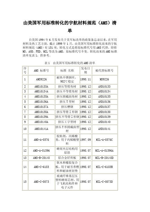
由美国军用标准转化的宇航材料规范(AMS)清
单
自美国1994年6月发布关于美军标改革的政策备忘录以来,在军用材料及热工艺方面,截止1999年1月,由美国军用标准转化而来的宇航材料规范(AMS)有151项,转化方式是将原标准代号用AMS代替,即将MS、AND、FED、MIL等改为AMS,原标准代号不变。
转化而来的AMS标准清单见表1,供参考。
表1 由美国军用标准转化的AMS清单
注:AND——美国空、海军航空设计标准(Air Force-Navy Aeronautical Design Standards, DOD);AS——美国宇航标准(Aerospace Standards, SAE);FED——美国联邦标准(FEDeral Standards);MIL——美国军用标准(MILitary Standards, DOD);MS——美国军用标准图纸(Military Standard Drawings);QQ——美国联邦规范(Federal Specifications)。
- 1、下载文档前请自行甄别文档内容的完整性,平台不提供额外的编辑、内容补充、找答案等附加服务。
- 2、"仅部分预览"的文档,不可在线预览部分如存在完整性等问题,可反馈申请退款(可完整预览的文档不适用该条件!)。
- 3、如文档侵犯您的权益,请联系客服反馈,我们会尽快为您处理(人工客服工作时间:9:00-18:30)。
__________________________________________________________________________________________________________________________________________ SAE Technical Standards Board Rules provide that: “This report is published by SAE to advance the state of technical and engineering sciences. The use of this report is entirely voluntary, and its applicability and suitability for any particular use, including any patent infringement arising therefrom, is the sole responsibility of the user.”SAE reviews each technical report at least every five years at which time it may be revised, reaffirmed, stabilized, or cancelled. SAE invites your written comments and suggestions.Copyright © 2016 SAE InternationalAll rights reserved. No part of this publication may be reproduced, stored in a retrieval system or transmitted, in any form or by any means, electronic, mechanical, photocopying, recording, or otherwise, without the prior written permission of SAE.TO PLACE A DOCUMENT ORDER: Tel: 877-606-7323 (inside USA and Canada)Tel: +1 724-776-4970 (outside USA)Fax: 724-776-0790Email: CustomerService@SAE WEB ADDRESS: SAE values your input. To provide feedback on this Technical Report, please visit/technical/standards/AMS2241SAEROSPACEMATERIAL SPECIFICATION AMS2241™REV. SIssued 1945-05Reaffirmed 2012-10Revised 2016-01Superseding AMS2241RTolerances, Corrosion and Heat-Resistant Steel, Iron Alloy,Titanium, and Titanium Alloy Bars and WireRATIONALEAMS2241S revises tolerances for machined bars (2.1.4, Table 3), clarifies the intent of precision ground or precision polished rounds (2.1.6, Table 5), and is a Five Year Review and update of this specification.1. SCOPEThis specification covers established manufacturing tolerances applicable to corrosion and heat-resistant steel, iron alloy, titanium, and titanium alloy bars and wire. These tolerances apply to all conditions, unless otherwise noted. The term “excl” is used to apply only to the higher figure of the specified range.2. DIAMETER, THICKNESS, AND WIDTHSpecified dimensions apply to diameter of rounds, to distance between parallel sides of hexagons and squares, and separately to width and thickness of rectangles.2.1 Cold Finished2.1.1 Cold Drawn Rounds, Squares, Hexagons, and Octagons (see 2.1.3)Shall be as shown in Table 1.Table 1A - Tolerances, diameter or thickness, inch/pound unitsSpecified Diameter or ThicknessInches Tolerance, InchPlus and Minus(see 2.1.1.1)RoundsTolerance, InchMinus OnlySquares, Hexagons,and Octagons(see 2.1.1.2)Over 0.500 to 1.000, excl 0.002 0.0041.000 0.0025 0.004 Over 1.000 to 1.500, excl 0.0025 0.0061.500 to2.000, incl 0.003 0.006 Over 2.000 to3.000, incl 0.003 0.008 Over 3.000 to4.000, incl 0.003 0.010 Table 1B - Tolerances, diameter or thickness, SI unitsSpecified Diameter or ThicknessMillimeters Tolerance, MillimeterPlus and Minus(see 2.1.1.1)RoundsTolerance, MillimeterMinus OnlySquares, Hexagons,and Octagons(see 2.1.1.2)Over 12.50 to 25.00, excl 0.05 0.1025.00 0.062 0.10Over 25.00 to 37.50, excl 0.062 0.1537.50 to 50.00, incl 0.08 0.15Over 50.00 to 75.00, incl 0.08 0.20Over 75.00 to 100.00, incl 0.08 0.252.1.1.1 Size tolerances for round bars are plus and minus as shown in Table 1. When required, however, they may bespecified all plus and nothing minus, or all minus and nothing plus, or any combination of plus and minus, if the total spread in size tolerance for a specified size is not less than the total spread shown in Table 1.2.1.1.2 For titanium and titanium alloys, the difference among the three measurements of the distance between oppositefaces of hexagons shall be not greater than one-half the size tolerance and the difference between the measurements of the distance between opposite faces of octagons shall be not greater than the size tolerance.2.1.2 Cold Drawn Flats (see 2.1.3)Shall be as shown in Table 2.Table 2A - Tolerances, thickness and width, inch/pound unitsSpecified WidthInchesThicknessTolerance, InchPlus and MinusWidthTolerance, InchPlus and Minus0.125 to 0.250, incl 0.002 0.004 Over 0.250 to 1.000, incl 0.002 0.002 Over 1.000 to 2.000, incl 0.003 0.003 Over 2.000 to 3.000, incl 0.004 0.004 Over 3.000 to 4.500, incl 0.005 0.005Table 2B - Tolerances, thickness and width, SI unitsSpecified Width MillimetersThicknessTolerance, MillimeterPlus and MinusWidthTolerance, MillimeterPlus and Minus3.00 to 6.00, incl 0.05 0.10Over 6.00 to 25.00, incl 0.05 0.05Over 25.00 to 50.00, incl 0.08 0.08Over 50.00 to 75.00, incl 0.10 0.10Over 75.00 to 115.00, incl 0.12 0.12If cold drawn bars are ordered heat treated or heat treated and pickled after cold finishing, tolerances shall be double those of Table 1 and Table 2.2.1.3 Machined or Turned Bars2.1.3.1 RoundsTolerances for machined or turned round bars 0.375 inch (9.53 mm) and over in specified diameter or thickness are shown in Table 3. Bars up to 0.375 inch (9.53 mm), exclusive, in specified diameter or thickness are commonly supplied centerless ground.Table 3A - Tolerances, machined or turned bars, inch/pound unitsSpecified Diameter or ThicknessInches Toleranceplus onlyInchOut of RoundInch0.375 to 2.000, incl 0.016 0.008 Over 2.000 to 4.000, incl 0.031 0.016Over 4.000 to 4.500, incl Over 4.500 to 5.500, incl Over 5.500 to 6.500, incl Over 6.500 to 8.000, incl Over 8.000 to 12.000, incl Over 12.000 to 15.000, incl Over 15.000 to 25.000, incl 0.0620.0780.1250.1560.1870.2190.2500.0460.0580.0700.0850.0940.1090.125Table 3B - Tolerances, machined or turned bars, SI unitsSpecified Diameter or ThicknessMillimeters Toleranceplus onlyMillimeterOut of RoundMillimeter9.525 to 50.80, incl 0.406 0.203 Over 50.80 to 101.6, incl 0.787 0.406Over 101.6 to 115.0, incl Over 115.0 to 140.0, incl Over 140.0 to 165.0, incl Over 165.0 to 200.0, incl Over 200.0 to 300.0, incl Over 300.0 to 400.0, incl Over 400.0 to 625.0, incl 1.6002.0003.0004.0004.8005.5006.5001.2001.5001.8002.2002.4002.8003.2002.1.3.2FlatsTolerances for machined flat bars shall be as agreed upon by purchaser and producer. 2.1.4Centerless Ground or Polished Round BarsTolerances for centerless ground or polished bars 0.125 to 4.062 inches (3.18 to 103.17 mm), inclusive, in specified diameter are shown in Table 4. Bars over 4.062 inches (103.17 mm) specified diameter are commonly supplied machined.Table 4A - Tolerances, centerless-ground or polished bars, inch/pound unitsSpecified Diameter InchesTolerance plus or minusInch Out of RoundInch 0.125 to 0.3125, excl 0.001 0.001 0.3125 to 0.500, excl 0.0015 0.0015 0.500 to 1.000, excl 0.002 0.002 1.000 to 1.500, incl 0.0025 0.0025 Over 1.500 to 3.250, incl 0.003 0.003 Over 3.250 to 4.0620.0050.005Table 4B - Tolerances, centerless-ground or polished bars, SI units Specified Diameter Millimeters Tolerance plus or minus Millimeter Out of Round Millimeter 3.175 t o 7.938 , excl 0.025 0.025 7.938 t o 12.70, excl 0.038 0.038 12.70 to 25.40, excl 0.051 0.051 25.40 to 38.10, incl 0.064 0.064 Over 38.10 to 82.55, incl 0.076 0.076 Over 82.55 to 103.20.1270.1272.1.5Precision Ground or Precision Polished Round BarsShall be as shown in Table 5.Table 5A - Tolerances, precision ground or precision polished rounds, inch/pound unitsSpecified DiameterInchesTolerance Inch Minus only Up to 1.500, incl0.001 Over 1.500 to 2.500, excl 0.0015 Over 2.500 to 3.000, incl 0.002 Over 3.000 to 4.000, incl0.003Table 5B - Tolerances, precision ground or precision polished rounds, SI unitsSpecified DiameterMillimetersTolerance Millimeter Minus only Up to 38.1, incl0.03 Over 38.1 to 63.5, excl0.04 63.5 to 76.2, incl 0.05 Over 76.2 to 101.6, incl0.082.2 Cold Drawn Wire2.2.1 Rounds, Squares, Hexagons, and Octagons (see 2.2.1.1)Shall be as shown in Table 6.Table 6A - Tolerances, diameter or thickness, inch/pound unitsSpecified Diameter or ThicknessInchTolerance, InchPlus and MinusRounds and SquaresTolerance, InchMinus OnlyHexagons and Octagons(see 2.2.1.3)0.003 to 0.0048, excl 0.0001 -- 0.0048 to 0.008, excl 0.0002 -- 0.008 to 0.012, excl 0.0003 -- 0.012 to 0.024, excl 0.0004 (see 2.2.1.2) -- 0.024 to 0.033, excl 0.0005 (see 2.2.1.2) -- 0.033 to 0.044, excl 0.0008 -- 0.044 to 0.125, excl 0.001 -- 0.125 to 0.3125, excl 0.001 0.002 0.3125 to 0.500, excl 0.0015 0.003 0.500 0.002 0.004Table 6B - Tolerances, diameter or thickness, SI unitsSpecified Diameter or ThicknessMillimeters Tolerance, MillimeterPlus and MinusRounds and SquaresTolerance, MillimeterMinus OnlyHexagons and Octagons(see 2.2.1.3)0.08 to 0.12, excl 0.002 --0.12 to 0.20, excl 0.005 --0.20 to 0.30, excl 0.008 --0.30 to 0.60, excl 0.010 (see 2.2.1.2) --0.60 to 0.85, excl 0.012 (see 2.2.1.2) --0.85 to 1.10, excl 0.020 --1.10 to 3.15, excl 0.02 --3.15 to 7.80, excl 0.02 0.057.80 to 12.50, excl 0.038 0.0812.50 0.05 0.102.2.1.1 If cold drawn wire is ordered heat treated or heat treated and pickled after cold finishing, tolerances shall bedouble those of Table 6 for nominal sizes 0.024 inch (0.60 mm) and over.2.2.1.2 For titanium and titanium alloys, tolerances for these sizes are ±0.00075 inch (0.019 mm).2.2.1.3 For titanium and titanium alloys, the difference among the three measurements of the distance between oppositefaces of hexagons shall be not greater than one-half the size tolerance, and the difference among the four measurements of the distance between opposite faces of octagons shall be not greater than one-half the size tolerance.2.2.1.4 Out-of-RoundRound wire shall not be out-of-round by more than one-half of the total tolerance shown in Table 6.2.2.2 FlatsShall be as shown in Table 7.Table 7A - Tolerances, thickness, inch/pound unitsSpecified ThicknessInch Tolerance, Inch Plus and MinusUp to 0.029, excl 0.001 0.029 to 0.035, excl 0.0015 0.035 to 0.1875, excl 0.002 Table 7B - Tolerances, thickness, SI unitsSpecified Thickness Millimeters Tolerance, Millimeter Plus and MinusUp to 0.70, excl 0.020.70 to 0.90, excl 0.0380.90 to 4.75, excl 0.042.2.2.1 Width tolerances shall be ± 0.005 inch (0.12 mm) for nominal widths 0.0625 to 0.375 inch (1.59 to 9.53 mm),exclusive.2.3 Hot Finished Bars2.3.1 Hot Rolled2.3.1.1 Rounds and SquaresShall be as shown in Table 8. Out-of-round is the difference between the maximum and minimum diameters of the bar, measured at the same cross section. Out-of-square is the difference in the two dimensions at the same cross section of a square bar, each dimension being the distance between opposite faces.Table 8A - Tolerances, diameter or thickness, inch/pound unitsSpecifiedDiameter or ThicknessInches Tolerance, InchPlusTolerance, InchMinusOut-of-Roundor Out-or-SquareInch0.250 to 0.3125, incl 0.005 0.005 0.008 Over 0.3125 to 0.4375, incl 0.006 0.006 0.009 Over 0.4375 to 0.625, incl 0.007 0.007 0.010 Over 0.625 to 0.875, incl 0.008 0.008 0.012 Over 0.875 to 1.000, incl 0.009 0.009 0.013 Over 1.000 to 1.125, incl 0.010 0.010 0.015 Over 1.125 to 1.250, incl 0.011 0.011 0.016 Over 1.250 to 1.375, incl 0.012 0.012 0.018 Over 1.375 to 1.500, incl 0.014 0.014 0.021 Over 1.500 to 2.000, incl 1/64 1/64 0.023 Over 2.000 to 2.500, incl 1/32 0 0.023 Over 2.500 to 3.500, incl 3/64 0 0.035 Over 3.500 to 4.500, incl 1/16 0 0.046 Over 4.500 to 5.500, incl 5/64 0 0.058 Over 5.500 to 6.500, incl 1/8 0 0.070 Over 6.500 to 8.000, incl 5/32 0 0.085Table 8B - Tolerances, diameter or thickness, SI unitsSpecified Diameter or ThicknessMillimeters Tolerance,MillimetersPlusTolerance, MillimeterMinusOut-of-Roundor Out-or-SquareMillimeters6.25 to7.80, incl 0.12 0.12 0.20Over 7.80 to 11.00, incl 0.15 0.15 0.22 Over 11.00 to 15.75, incl 0.18 0.18 0.25 Over 15.75 to 22.00, incl 0.20 0.20 0.30 Over 22.00 to 25.00, incl 0.22 0.22 0.32 Over 25.00 to 28.00, incl 0.25 0.25 0.38 Over 28.00 to 31.00, incl 0.28 0.28 0.40 Over 31.00 to 34.00, incl 0.30 0.30 0.45 Over 34.00 to 37.50, incl 0.35 0.35 0.52 Over 37.50 to 50.00, incl 0.40 0.40 0.58 Over 50.00 to 62.50, incl 0.80 0 0.58 Over 62.50 to 87.50, incl 1.20 0 0.88 Over 87.50 to 115.00 incl 1.60 0 1.15 Over 115.00 to 138.00 incl 2.00 0 1.45 Over 138.00 to 165.00 incl 3.15 0 1.75 Over 165.00 to 200.00, incl 3.90 0 2.12 2.3.1.2 Hexagons and OctagonsShall be as shown in Table 9.Table 9A - Tolerances, thickness, inch/pound unitsSpecified ThicknessInches Tolerance, InchPlus and MinusMaximum Difference3 MeasurementsHexagons OnlyInch0.250 to 0.500, incl 0.007 0.011 Over 0.500 to 1.000, incl 0.010 0.015 Over 1.000 to 1.500, incl 0.021 0.025 Over 1.500 to 2.000, incl 1/32 1/32 Over 2.000 to 2.500, incl 3/64 3/64 Over 2.500 to 3.500, incl 1/16 1/16Table 9B - Tolerances, thickness, SI unitsSpecified Thickness Millimeters Tolerance, MillimetersPlus and MinusMaximum Difference3 MeasurementsHexagons OnlyMillimeters6.25 to 12.50, incl 0.18 0.28 Over 12.50 to 25.00, incl 0.25 0.38 Over 25.00 to 37.50, incl 0.52 0.62 Over 37.50 to 50.00, incl 0.78 0.78 Over 50.00 to 62.50, incl 1.18 1.18 Over 62.50 to 87.50, incl 1.56 1.56Shall be as shown in Tables 10 and 11.Table 10A - Tolerances, thickness, inch; for thickness ranges, inches, inch/pound unitsSpecified Width,Inches 0.125 to0.500,inclPlus &MinusOver0.500 to1.000,inclPlus &MinusOver1.000 to2.000,inclPlus &MinusOver2.000 to4.000,inclPlusOver2.000 to4.000,inclMinusOver4.000 to6.000,inclPlusOver4.000 to6.000,inclMinusOver6.000 to8.000,inclPlusOver6.000 to8.000,inclMinusUp to 1.000, incl 0.008 0.010 - - - - - - - Over 1.000 to 2.000, incl 0.012 0.015 0.031 - - - - - - Over 2.000 to 4.000, incl 0.015 0.020 0.031 0.062 0.031 - - - - Over 4.000 to 6.000, incl 0.015 0.020 0.031 0.062 0.031 0.093 0.062 - - Over 6.000 to 8.000, incl 0.016 0.025 0.031 0.062 0.031 0.093 0.062 0.125 0.156 Over 8.000 to 10.000, incl 0.021 0.031 0.031 0.062 0.031 0.093 0.062 0.125 0.156 Table 10B - Tolerances, thickness, millimeters; for thickness ranges, millimeters, SI unitsSpecified Width, Millimeters 3.10 to12.50,inclPlus &MinusOver12.50 to25.00,inclPlus &MinusOver25.00 to50.00,inclPlus &MinusOver50.00 to100.00,inclPlusOver50.00 to100.00,inclMinusOver100.00 to150.00,inclPlusOver100.00 to150.00,inclMinusOver150.00 to200.00,inclPlusOver150.00 to200.00,inclMinusUp to 25.00, incl 0.20 0.25 - - - - - - - Over 25.00 to 50.00, incl 0.30 0.38 0.78 - - - - - - Over 50.00 to 100.00, incl 0.38 0.50 0.78 1.55 0.78 - - - - Over 100.00 to 150.00, incl 0.38 0.50 0.78 1.55 0.78 2.32 1.55 - - Over 150.00 to 200.00, incl 0.40 0.62 0.78 1.55 0.78 2.32 1.55 3.12 3.90 Over 200.00 to 250.00, incl 0.52 0.78 0.78 1.55 0.78 2.32 1.55 3.12 3.90Table 11A - Tolerances, width, inch/pound unitsSpecified Width,Inches Tolerance, InchPlusTolerance, InchMinusUp to 1.000, incl 0.015 0.015 Over 1.000 to 2.000, incl 0.031 0.031 Over 2.000 to 4.000, incl 0.062 0.031 Over 4.000 to 6.000, incl 0.093 0.062 Over 6.000 to 8.000, incl 0.125 0.156 Over 8.000 to 10.000, incl 0.156 0.187 Table 11B - Tolerances, width, SI unitsSpecified Width, Millimeters Tolerance,MillimetersPlusTolerance,MillimetersMinusUp to 25.00, incl 0.38 0.38 Over 25.00 to 50.00, incl 0.78 0.78 Over 50.00 to 100.00, incl 1.55 0.78 Over 100.00 to 150.00, incl 2.32 1.55 Over 150.00 to 200.00, incl 3.12 3.90 Over 200.00 to 250.00, incl 3.90 4.68Tolerances shall be as agreed upon by purchaser and producer.3. LENGTHTolerances in Table 12 and Table 13 shall apply only when exact lengths are ordered.3.1 Hot or Cold Finished BarsShall be as shown in Table 12.Table 12A - Tolerances, length, inches, plus only;for length ranges, feet, inch/pound unitsSpecifiedDiameter of Rounds,Thickness of Squares,Hexagons, and Octagons, Width of FlatsInchesLengthUp to 12 feet,Incl (inches)LengthOver 12 to 25 feet,Incl (inches)Up to 2.000, incl 1/2 3/4 Over 2.000 to 4.000, incl 3/4 1 Over 4.000 to 6.000, incl 1 1-1/4 Over 6.000 to 9.000, incl 1-1/4 1-1/2 Over 9.000 to 12.000, incl 1-1/2 2 Table 12B - Tolerances, length, millimeters, plus only;for length ranges, millimeters, SI unitsSpecifiedDiameter of Rounds,Thickness of Squares,Hexagons, and Octagons, Width of FlatsMillimetersLengthUp to 3600,InclLengthOver 3600 to 7500,InclUp to 50.00, incl 12.5 19.0Over 50.00 to 100.00, incl 19.0 25.0Over 100.00 to 150.00, incl 25.0 31.0Over 150.00 to 225.00, incl 31.0 37.5Over 225.00 to 300.00, incl 37.5 50.0 3.2 Wire3.2.1 Round and Shape, Straightened and Cut, Exact Length ReshearedShall be as shown in Table 13.Table 13A - Tolerances, length, inch, plus only;for length ranges, feet, inch/pound unitsSpecifiedDiameter of Rounds,Thickness of Squares, Hexagons, and Octagons,InchesLengthUp to 3 feet,Excl (inches)Length3 to 12 feet,Incl (inches)LengthOver 12 to 25 feet,Incl (inches)Up to 0.125, incl 1/16 1/16 1/8 Over 0.125 to 0.500, incl 1/32 (see 3.2.1.1) 1/16 1/8Table 13B - Tolerances, length, millimeters, plus only;for length ranges, millimeters, SI units SpecifiedDiameter of Rounds,Thickness of Squares, Hexagons, and Octagons,MillimetersLengthUp to 900,ExclLength900 to 3600,InclLengthOver 3600 to 7500,InclUp to 3.12, incl 1.6 1.6 3.1Over 3.12 to 12.50, incl 0.8 (see 3.2.1.1) 1.6 3.13.2.1.1 For titanium and titanium alloys, tolerance for these sizes is +1/16 inch, -0 inch (+1.6 mm, -0 mm).4. STRAIGHTNESS4.1 Cold FinishedBars shall be of such straightness that the maximum curvature (depth of arc) shall not exceed 0.0625 inch (1.59 mm) in any 5 feet (1500 mm) of length, but shall not exceed 0.0125 inch (1.04 mm) x length in feet (meters).4.2 Hot Finished or Heat TreatedUnless otherwise ordered, bars shall be of such straightness that the maximum curvature (depth of arc) shall not exceed 0.125 inch (3.13 mm) in any 5 feet (1500 mm) of length, but shall not exceed 0.025 inch (2.08 mm) x length in feet (meters).5. SPECIAL TOLERANCES5.1 Across Corners, HexagonsThe requirements shown in Table 14 apply to cold finished hexagons, when specified.Table 14A - Minimum distance across corners, inch/pound unitsSpecified ThicknessInches Distance Across CornersInches0.1875 0.2188 0.250 0.3125 0.375 0.210 0.245 0.280 0.351 0.4230.4375 0.500 0.5625 0.5938 0.625 0.492 0.564 0.635 0.670 0.7060.6875 0.750 0.8125 0.875 0.9375 0.775 0.848 0.9190.9901.0621.000 1.0625 1.133 1.203SAE INTERNATIONAL AMS2241™S Page 11 of 11Table 14B - Minimum distance across corners, SI unitsSpecified Thickness Millimeters Distance Across CornersMillimeters4.505.506.508.009.5011.0012.5014.0015.0016.0017.5019.0020.50 22.0024.0025.00 27.005.046.177.318.97 10.67 12.3714.0515.7516.8818.0119.71 21.4123.1124.8127.0828.21 30.426. NOTES6.1 Revision IndicatorA change bar (l) located in the left margin is for the convenience of the user in locating areas where technical revisions, not editorial changes, have been made to the previous issue of this document. An (R) symbol to the left of the document title indicates a complete revision of the document, including technical revisions. Change bars and (R) are not used in original publications, nor in documents that contain editorial changes only.6.2 Terms used in AMS are clarified in ARP1917.6.3 Dimensions and properties in inch/pound units and the Fahrenheit temperatures are primary; dimensions andproperties in SI units and the Celsius temperatures are shown as the approximate equivalents of the primary units and are presented only for information.PREPARED BY AMS COMMITTEE “F”。