FLUSH MOUNT MOLDING MATERIALS _TSM7102G_ 2版
STTH2002G中文资料
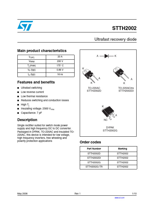
May 2006 Rev 11/10STTH2002Ultrafast recovery diodeMain product characteristicsFeatures and benefits■Ultrafast switching ■Low reverse current ■Low thermal resistance■Reduces switching and conduction losses ■High T j■Insulating voltage: 2500 V rms ■Capacitance: 7 pFDescriptionSingle rectifier suited for switch mode power supply and high frequency DC to DC converter. Packaged in D²P AK, TO-220AC and insulated TO-220AC, this device is intended for low voltage, high frequency inverters, free wheeling and polarity protection applicationsOrder codesI F(AV)20 A V RRM 200 V T j (max)175° C V F (typ)0.86 V t rr (typ)16 nsPart Number Marking STTH2002D STTH2002STTH2002DI STTH2002STTH2002G STTH2002STTH2002G-TRSTTH2002Characteristics STTH20022/101 CharacteristicsTo evaluate the conduction losses use the following equation: P = 0.75 x I F(AV) + 0.01 I F 2(RMS)Table 1.Absolute ratings (limiting values at T j = 25° C, unless otherwise specified)Symbol ParameterValue Unit V RRM Repetitive peak reverse voltage 200V I F(RMS)RMS forward current35A I F(AV)Average forward current, δ = 0.5TO-220AC, D 2P AK T c = 120° C 20A TO-220ACins T c = 60° CI FSM Surge non repetitive forward current t p = 10 ms Sinusoidal175A T stg Storage temperature range-65 to + 175° C T jMaximum operating junction temperature175° CTable 2.Thermal parametersSymbol ParameterValue Unit R th(j-c)Junction to caseTO-220AC, D 2P AK 2.4° C/WTO-220ACins5Table 3.Static electrical characteristicsSymbol ParameterTest conditionsMin.TypMax.Unit I R (1)Reverse leakage currentT j = 25° C V R = V RRM10µAT j = 125° C 10100V F (2)Forward voltage dropT j = 25° C I F = 20 A1 1.1V T j = 150° C0.860.95T j = 25° C I F = 25 A1.15T j = 125° C 0.94 1.05T j = 150° C0.911.Pulse test: t p = 5 ms, δ < 2 %2.Pulse test: t p = 380 µs, δ < 2 %STTH2002Characteristics3/10Table 4.Dynamic characteristicsSymbolParameterTest conditionsMin.Typ Max.Unitt rrReverse recovery timeI F = 1 A, dI F /dt = -200 A/µs,V R = 30 V , T j = 25 °C 1620nsI F = 1 A, dI F /dt = -50 A/µs,V R = 30 V , T j = 25 °C 3340I RM Reverse recovery current I F = 20 A, dI F /dt = 100 A/µs,V R = 160 V , T j = 125 °C 810A t fr Forward recovery time I F = 20 A, dI F /dt = 100 A/µs V FR = 1.1 x V Fmax , T j = 25 °C 230ns V FPForward recovery voltageI F = 20 A, dI F /dt = 100 A/µs,V FR = 1.1 x V Fmax , T j = 25 °C2V Figure 1.Peak current versus duty cycle Figure 2.Forward voltage drop versusd Tδ=tp/T tpFigure 3.Forward voltage drop versusforward current (maximum values)Figure 4.Relative variation of thermal impedance, junction to case,CharacteristicsSTTH20024/10Figure 5.Junction capacitance versus reverse applied voltage (typicalFigure 6.Reverse recovery charges versus dI F /dt (typical values)Figure 7.Reverse recovery time versusFigure 8.Peak reverse recovery current Figure 9.Dynamic parameters versus junction temperatureFigure 10.Thermal resistance, junction toambient, versus copper surface under tab (Epoxy printed circuit2STTH2002Ordering information scheme 2 Ordering information scheme5/10Package information STTH20026/103 Package informationEpoxy meets UL94, V0Cooling method: by conduction (C)Recommended torque value: 0.8 Nm Maximum torque value: 1.0 NmSTTH2002Package information7/10Package information STTH20028/102In order to meet environmental requirements, ST offers these devices in ECOP ACK® packages. These packages have a lead-free second level interconnect. The category of second level interconnect is marked on the package and on the inner box label, in compliance with JEDEC Standard JESD97. The maximum ratings related to soldering conditions are also marked on the inner box label. ECOP ACK is an ST trademark. ECOP ACK specifications are available at: .2STTH2002Ordering information9/104 Ordering information5 Revision historyPart Number Marking Package Weight Base qtyDelivery modeSTTH2002D STTH2002TO-220AC 1.90 g 50Tube STTH2002DI STTH2002TO-220ACins 2.30 g 50Tube STTH2002G STTH2002D 2P AK 1.48 g 50Tube STTH2002G-TRSTTH2002D 2P AK1.48 g1000Tape and reelDate RevisionDescription of Changes03-May-20061First issueSTTH200210/10Please Read Carefully:Information in this document is provided solely in connection with ST products. STMicroelectronics NV and its subsidiaries (“ST”) reserve the right to make changes, corrections, modifications or improvements, to this document, and the products and services described herein at anytime, without notice.All ST products are sold pursuant to ST’s terms and conditions of sale.Purchasers are solely responsible for the choice, selection and use of the ST products and services described herein, and ST assumes no liability whatsoever relating to the choice, selection or use of the ST products and services described herein.No license, express or implied, by estoppel or otherwise, to any intellectual property rights is granted under this document. If any part of this document refers to any third party products or services it shall not be deemed a license grant by ST for the use of such third party products or services, or any intellectual property contained therein or considered as a warranty covering the use in any manner whatsoever of such third party products or services or any intellectual property contained therein.UNLESS OTHERWISE SET FORTH IN ST’S TERMS AND CONDITIONS OF SALE ST DISCLAIMS ANY EXPRESS OR IMPLIED WARRANTY WITH RESPECT TO THE USE AND/OR SALE OF ST PRODUCTS INCLUDING WITHOUT LIMITATION IMPLIED WARRANTIES OF MERCHANTABILITY, FITNESS FOR A PARTICULAR PURPOSE (AND THEIR EQUIVALENTS UNDER THE LAWS OF ANY JURISDICTION), OR INFRINGEMENT OF ANY PATENT, COPYRIGHT OR OTHER INTELLECTUAL PROPERTY RIGHT. UNLESS EXPRESSLY APPROVED IN WRITING BY AN AUTHORIZE REPRESENTATIVE OF ST, ST PRODUCTS ARE NOT DESIGNED, AUTHORIZED OR WARRANTED FOR USE IN MILITARY, AIR CRAFT, SPACE, LIFE SAVING, OR LIFE SUSTAINING APPLICATIONS, NOR IN PRODUCTS OR SYSTEMS, WHERE FAILURE OR MALFUNCTION MAY RESULT IN PERSONAL INJURY, DEATH, ORSEVERE PROPERTY OR ENVIRONMENTAL DAMAGE.Resale of ST products with provisions different from the statements and/or technical features set forth in this document shall immediately void any warranty granted by ST for the ST product or service described herein and shall not create or extend in any manner whatsoever, anyliability of ST.ST and the ST logo are trademarks or registered trademarks of ST in various countries.Information in this document supersedes and replaces all information previously supplied.The ST logo is a registered trademark of STMicroelectronics. All other names are the property of their respective owners.© 2006 STMicroelectronics - All rights reservedSTMicroelectronics group of companiesAustralia - Belgium - Brazil - Canada - China - Czech Republic - Finland - France - Germany - Hong Kong - India - Israel - Italy - Japan - Malaysia - Malta - Morocco - Singapore - Spain - Sweden - Switzerland - United Kingdom - United States of America。
A7102中文版
Preliminary 868/915MHz FSK TransceiverDocument Title868/915MHz FSK TransceiverRevision HistoryRev. No.History Issue Date Remark0.0 Preliminary June 25 , 2007Important Notice:AMIC-COM reserves the right to make changes to its products or to discontinue any integrated circuit product or service without notice. AMIC-COM integrated circuit products are not designed, intended, authorized, or warranted to be suitable for use in life-support applications, devices or systems or other critical applications. Use of AMIC-COM products in such applications is understood to be fully at the risk of the customer.Preliminary 868/915MHz FSK TransceiverTable of contents1. 一般描述 (General Description) (4)2. 基本應用 (Typical Applications) (4)3. 特性 (Features) (4)4. 接腳配置(Pin Configurations) (4)5. RF Chip方塊圖 (Block Diagram) (5)6. 絕對最大範圍 (6)7. 接腳說明 (8)8. 控制暫存器 (Control Register) (9)8.1 Control Register Summary (9)8.2 控制暫存器說明 (Control Register Description): (10)8.2.1 System clock (Address: 00h) (10)9. SPI串列介面控制9.1 SPI格式9.2 SPI時序圖9.39.4 SPI時序特性10 振盪電路連接10.1使用石英晶體10.2使用外部時脈11. 系統時脈11.1 clock chain 機制11.1.1不使用clock chain (26)11.1.2 使用基頻參考信號(GRCK)800KHz設置 (26)11.1.3使用基頻參考信號(GRCK)1.2MHz設置 (26)12. 工作頻率設定 (27)12.1 PLL I及PLL II的設定 (27)13. 系統狀態機制 (State machine) (28)14. CAL state的校準 (30)14.1 校準程序 (Calibration Process) (30)15. VCO band校準 (30)15.1 校準程序 (Calibration Process) (30)16. FIFO (First In First Out)功能 (31)16.1傳送封包格式 (31)16.2 封包處理 (Packet Handling) (31)16.3資料傳送時間計算 (32)16.4 TX/RX FIFO (32)16.5 FIFO pointer margin threshold (32)17. 工作模式 (Mode of operation) (34)17.1 Direct mode (34)17.1.1 TX傳送時序 (34)Preliminary 868/915MHz FSK Transceiver17.1.2 RX傳送時序 (35)17.2 FIFO mode (36)17.2.1 TX傳送時序 (36)17.2.2 RX接收時序 (37)18. ADC (Analog Digital Converter) (38)18.1 溫度量測 (38)18.2 RSSI量測 (38)18.3載波(Carrier)偵測 (38)18.4外部信號源量測 (38)19. 應用電路(Application Circuit) (39)20. 包裝資訊(Package Information) (40)21. 產品資訊(Ordering Information) (41)Preliminary 868/915MHz FSK Transceiver1. 一般描述(General Description) A7102B 是一單晶片CMOS 製程,用於868/915MHz ISM 頻段的無線應用IC 。
NXT 编程手册
购入后如要转卖给第三方,请务必事先与我公司联系。
模组型高速多功能贴片机NXT编程手册本机器手册包含下列内容。
NXT安装手册NXT系统手册NXT机械手册FUJI智能供料器使用手册NXT编程手册为了您能安全高效地使用本机器,请仔细阅读以上手册,并遵守上面记载的步骤及注意事项。
请将手册放置在机器附近,以便使用时能立即浏览。
QD025-00著作权本手册的著作权属于富士机械制造株式会社所有。
未经本公司同意,严禁任意复制和转载本手册中的部分或全部内容。
商标保证和责任本公司对在使用富士产品的时候,由于没有使用纯正的富士公司所生产的零部件制品,或者由于使用者的不恰当的设定以及不合适的使用环境而所产生的结果及其所造成的影响不负任何责任。
注意事项· 本手册中的内容在没有预告的情况下,有进行变更的可能性。
· 本手册中的内容在编写时虽力求精益求精,万一有错误之处敬请和本公司联系。
· 除了因本公司制品所引起的故障以外,本公司对于使用本手册的结果及其所造成的影响不负任何责任。
QD025-00目录目录1. Fuji Flexa与NXT机 (1)1.1 序言 (1)2. Job编制器 (3)2.1 序言 (3)2.2 创建Job的基本操作方法 (3)2.2.1 从修改已有Job开始 (3)2.2.2 从手动输入顺序数据开始 (3)2.2.3 从导入Centroid CAD数据开始 (4)2.2.4 从导入CCIMF数据开始 (4)2.2.5 从导入MCSIMF文件开始 (5)2.2.6 从导入Allegro CAD数据开始 (5)2.2.7 从导入Mentor CAD数据开始 (6)2.2.8 从导入CR5000(PWS/Board Designer) CAD数据开始 (6)2.2.9 从导入OrCAD CAD数据开始 (7)2.2.10 从导入SFX-J1 CAD数据开始 (7)2.2.11 从导入Specctra CAD数据开始 (8)2.2.12 从导入PowerPCB CAD数据开始 (8)2.2.13 从导入PanaCAD数据开始 (9)2.3 NXT的设定方法 (10)2.3.1 将当前Job的生产线设定更改为NXT机的生产线设定 (10)2.3.2 将NXT机添加至Job (10)2.3.3 编辑NXT机的Configuration数据 (11)2.4 生产线平衡 (17)2.5 优化 (18)2.5.1 在Job编制器中进行优化 (18)2.5.2 Dual Job Optimize (18)2.6 生成报告 (20)2.6.1 手动生成报告 (20)2.6.2 在保存Job时自动创建生产程序 (20)3. 元件数据 (21)3.1 序言 (21)目录QD025-003.2 元件数据 (22)3.2.1 元件数据详情 (22)3.3 Shape Data (24)3.3.1 Shape information详情 (26)3.3.2 形状过外形程详情 (29)3.4 Package Data (33)3.4.1 Package information详情 (33)3.4.2 Package process详情 (34)3.5 关于P_pattern (36)3.5.1 NXT机可使用的P_patern (36)3.5.2 NXT机无法使用的P_pattern (37)3.5.3 P_pattern详情 (38)3.5.4 P_Pattern选择表 (43)3.6 Vision Type详情 (45)3.6.1 关于元件基准点 (45)3.6.2 NXT机Vision Type 输入说明 (46)3.7 同已有PD之间的兼容性 (60)3.7.1 原因 (60)3.7.2 已有机种的Vision Type和NXT机的Vision Type对照一览表 (61)3.7.3 设置元件数据的“Override” (66)4. Job传输 (67)4.1 序言 (67)4.2 传输 (68)4.2.1 从Job创建器传输Job (68)4.2.2 拖放Job以进行传输 (68)4.2.3 使用[传输]指令进行传输 (69)4.3 基本操作方法 (70)4.3.1 更改当前Job (70)4.3.2 从机器中删除Job (70)5. Fujitrax与NXT (71)5.1 序言 (71)6. Fujitrax Verifier (73)6.1 序言 (73)6.2 必需条件 (73)QD025-00目录6.2.1 安装和运行Central Server (73)6.2.2 在Fujitrax的生产线结构中添加NXT机 (73)6.2.3 NXT机的Fujitrax configuration设置 (74)6.2.4 Kit Handy access的用户注册 (75)6.3 将供料器和料卷进行关联 (76)6.3.1 ID创建方法 (76)6.3.2 快速检验的执行方法 (76)6.4 进行供料装置检查 (78)6.4.1 使用Kit Handy (78)6.5 供料装置状态检查 (79)6.5.1 使用Kit Manager时 (79)6.5.2 使用Kit Handy时 (79)6.6 在生产中补给元件 (80)6.6.1 更换供料器 (80)6.6.2 料带拼接 (80)7. 用语表 (83)7.1 英文、数字 (83)7.2 拼音:B (83)7.3 拼音:C (83)7.4 拼音:D (84)7.5 拼音:F (84)7.6 拼音:G (84)7.7 拼音:H (85)7.8 拼音:J (85)7.9 拼音:L (86)7.10 拼音:M (86)7.11 拼音:Q (86)7.12 拼音:R (86)7.13 拼音:S (86)7.14 拼音:T (87)7.15 拼音:W (87)7.16 拼音:X (87)7.17 拼音:Y (88)7.18 拼音:Z (88)目录QD025-00 MEMO:QD025-00关于本手册关于本手册本手册介绍Fuji Flexa和Fujitrax的操作方法,以及有关NXT机的元件数据的详细情况。
1971002资料
http://eshop.phoenixcontact.de/phoenix/treeViewClick.do?UID=1971002
Nominal current IN AWG/kcmil CUL Nominal voltage UN Nominal current IN AWG/kcmil UL Nominal voltage UN Nominal current IN AWG/kcmil Certification
Certificates / Approvals
Approval logo
CSA Nominal voltage UN 300 V
PHOENIX CONTACT GmbH & Co. KG http://www.phoenixcontact.de
Page 1 / 3 Mar 8, 2008
元器件交易网
元器件交易网
Extract from the online catalog
SMSTB 2,5/15-STF
Order No.: 1971002
The figure shows a 10-position version of the product
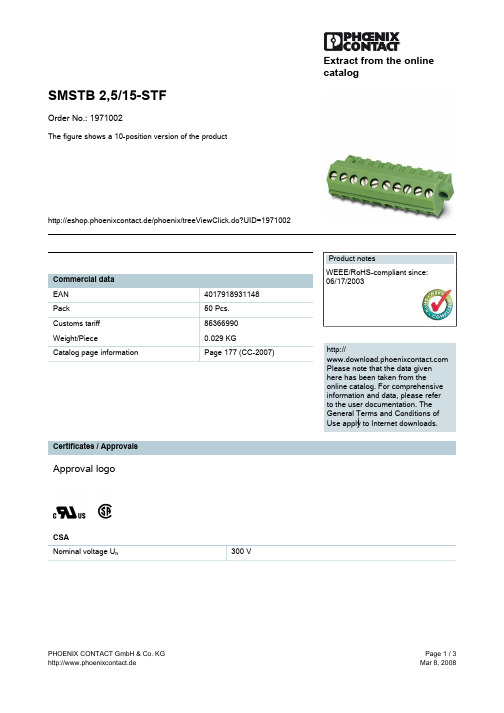
http://eshop.phoenixcontact.de/phoenix/treeViewClick.do?UID=1971002 Product notes Commercial data EAN Pack Customs tariff Weight/Piece Catalog page information 4017918931148 50 Pcs. 85366990 0.029 KG Page 177 (CC-2007) http:// Please note that the data given here has been taken from the online catalog. For comprehensive information and data, please refer to the user documentation. The General Terms and Conditions of Use apply to Internet downloads. WEEE/RoHS-compliant since: 06/17/2003
V23833-G9909-Z100资料
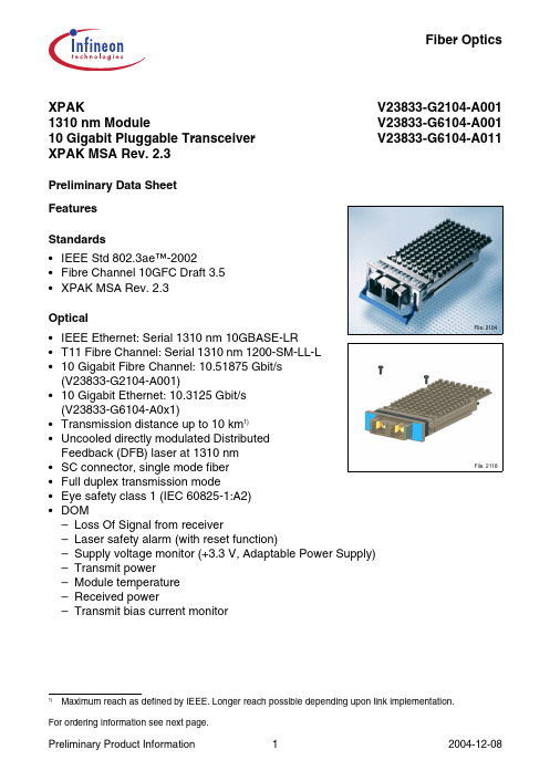
XPAK1310 nm Module10 Gigabit Pluggable Transceiver XPAK MSA Rev. 2.3V23833-G2104-A001 V23833-G6104-A001 V23833-G6104-A011Preliminary Data SheetFiber OpticsFor ordering information see next page.File: 2104 File: 2118FeaturesStandards•IEEE Std802.3ae™-2002•Fibre Channel 10GFC Draft 3.5•XPAK MSA Rev. 2.3Optical•IEEE Ethernet: Serial 1310 nm 10GBASE-LR•T11 Fibre Channel: Serial 1310 nm 1200-SM-LL-L•10 Gigabit Fibre Channel: 10.51875 Gbit/s(V23833-G2104-A001)•10 Gigabit Ethernet: 10.3125 Gbit/s(V23833-G6104-A0x1)•Transmission distance up to 10 km1)•Uncooled directly modulated DistributedFeedback (DFB) laser at 1310 nm•SC connector, single mode fiber•Full duplex transmission mode•Eye safety class 1 (IEC 60825-1:A2)•DOM–Loss Of Signal from receiver–Laser safety alarm (with reset function)–Supply voltage monitor (+3.3 V, Adaptable Power Supply)–Transmit power–Module temperature–Received power–Transmit bias current monitor1)Maximum reach as defined by IEEE. Longer reach possible depending upon link implementation.FeaturesElectrical•Hot pluggable•Power supply: +5.0 V, +3.3 V, Adaptable Power Supply (APS: +1.8 V)•Total power consumption: 3.3 W typical•XAUI electrical interface– 3.125 Gbit/s Ethernet (V23833-G61xx-xxxx)– 3.1875 Gbit/s Fibre Channel (V23833-G21xx-xxxx)•Management and control via MDIO 2-wire bus•70-pin connectorMechanical•Mezzanine profile: 2.68" L x 1.42" W x 0.38" H (68.07 mm x 35.99 mm x 9.8 mm)•Mezzanine module height for PCI card applications and mid-board mounting •Separated signal/chassis ground•Belly-to-belly applications•De-latch mechanism with low extraction force (V23833-Gxxxx-Ax0x only)•Built-in heat sinkApplications•10 Gbit/s Ethernet and Fibre Channel transmission systems for Long Range (LR) •Integration on PCI card•Mid-board mounting•Belly-to-belly for high density applications•Enterprise and campus network applications•Storage applications•Backplane and switch applications•Core and edge routers•Aggregation point for lower date rate•XPAK evaluation kit V23833-G9909-Z001 available upon requestOrdering InformationConnector Laser Class Part Number Standard De-LatchMechanismV23833-G2104-A001Fibre Channel Bail SC1V23833-G6104-A001Ethernet Bail SC1V23833-G6104-A011Ethernet None SC1Pin ConfigurationFigure1XPAK Transceiver Electrical Pad LayoutConnector Pin AssignmentsPin No.Signal Name Pin No.Signal Name 1GND70GND2GND69GND3GND68Reserved4+5.0 V DC Power67Reserved5+3.3 V DC Power66GND6+3.3 V DC Power65TX LANE3–7APS64TX LANE3+ 8APS63GND9LASI62TX LANE2–10RESET61TX LANE2+ 11Vendor Specific60GND12TX ON/OFF59TX LANE1–13Reserved58TX LANE1+ 14MOD DETECT57GND15Vendor Specific56TX LANE0–16Vendor Specific55TX LANE0+ 17MDIO54GND18MDC53GND19PRTAD452GND20PRTAD351RX LANE3–21PRTAD250RX LANE3+ 22PRTAD149GND23PRTAD048RX LANE2–24Vendor Specific47RX LANE2+ 25APS SET46GND26Reserved45RX LANE1–27APS SENSE44RX LANE1+ 28APS43GND29APS42RX LANE0–30+3.3 V DC Power41RX LANE0+ 31+3.3 V DC Power40GND32+5.0 V DC Power39Reserved33GND38Reserved34GND37GND35GND36GNDPin DescriptionSignal Name Level I/O Pin No.DescriptionManagement and Monitoring PortsMDIO Open Drain I/O17Management Data I/O. Requiresexternal 10 - 22 kΩ pull-up to 1.8 Von host.MDC 1.2 VCMOSI18Management Data Clock InputPRTAD4 1.2 VCMOSI19Port Address Input bit 4PRTAD3 1.2 VCMOSI20Port Address Input bit 3PRTAD2 1.2 VCMOSI21Port Address Input bit 2PRTAD1 1.2 VCMOSI22Port Address Input bit 1PRTAD0 1.2 VCMOSI23Port Address Input bit 0LASI Open Drain O9Link Alarm Status Interrupt Output.Open Drain Compatible Output with10 - 20 kΩ pull-up on host.Logic high = Normal OperationLogic low = Status Flag Triggered RESET Open Drain I10Reset Input.Open Drain Compatible Input with22 kΩ pull-up to APS internal totransceiver.Logic high = Normal OperationLogic low = RESETVendor Specific 11,15,16,24Vendor Specific Pins. Leaveunconnected when not used.TX ON/OFF Open Drain I12TX ON/OFF Input.Open Drain Compatible Input with22kΩ pull-up to APS internal totransceiver.Logic high = Transmitter OnLogic low = Transmitter OffMOD DETECT O14Pulled low inside transceiverthrough a 1 kΩ resistor to GroundTransmit FunctionsReserved Reserved II6867Reserved For Future UseReserved For Future UseTX LANE 3–TX LANE 3+AC-coupled,InternallybiaseddifferentialXAUIII6564Module XAUI Input Lane 3–Module XAUI Input Lane 3+TX LANE 2–TX LANE 2+II6261Module XAUI Input Lane 2–Module XAUI Input Lane 2+TX LANE 1–TX LANE 1+II5958Module XAUI Input Lane 1–Module XAUI Input Lane 1+TX LANE 0–TX LANE 0+II5655Module XAUI Input Lane 0–Module XAUI Input Lane 0+Receive FunctionsReserved Reserved OO3839Reserved For Future UseReserved For Future UseRX LANE 0+ RX LANE 0–AC-coupled,InternallybiaseddifferentialXAUIOO4142Module XAUI Output Lane 0+Module XAUI Output Lane 0–RX LANE 1+ RX LANE 1–OO4445Module XAUI Output Lane 1+Module XAUI Output Lane 1–RX LANE 2+ RX LANE 2–OO4748Module XAUI Output Lane 2+Module XAUI Output Lane 2–RX LANE 3+ RX LANE 3–OO5051Module XAUI Output Lane 3+Module XAUI Output Lane 3–Pin Description (cont’d)Signal Name Level I/O Pin No.DescriptionDC Power GND 0 V DCI1,2,3,33,34,35,36,37,40,43,46,49,52,53,54,57,60,63,66,69,70Ground connection for signal ground on the moduleAPS +1.8 V I 7,8,28,29Input from Adaptive Power Supply APS SENSE +1.8 V O 27APS Sense Output. Connected to the APS input inside transceiver.APS SETGNDI25Feedback input from APS. Connected to GND through a zero Ω resistor inside the transceiver.3.3 V +3.3 V DC I 5,6,30,31DC Power Input, +3.3 V DC, Nominal5.0 V +5.0 V DCI4,32DC Power Input, +5.0 V DC, NominalReserved 26Reserved for APD. Do not connect.Reserved13Reserved. Do not connect.Pin Description (cont’d)Signal Name Level I/O Pin No.DescriptionDescriptionSystem Block Diagram (10 Gbit/s Ethernet)Figure 2Optical Interface Standard Specifications•IEEE Std 802.3ae™-2002 clause 52, 10GBASE-LR •Fibre Channel 10GFC Draft 3.5, 1200-SM-LL-L •XPAK MSA 2.3Fiber Type Differential Group Delay Maximum (ps)Operating Range (meters)1)1)Operating range as defined by IEEE and Fibre Channel standards. Longer reach possible depending upon link implementation.B1.1 SMF 10 2 to 10,000B1.3 SMF102 to 10,000Electrical Interface Standard Specifications•IEEE Std802.3ae™-2002 clause 45 & 47•XPAK MSA 2.3Environment: Thermal Management RecommendationsOperating air inlet temperature:0°C - 50°COperating Airflow: 3 m/s maximum defined per XPAK MSA Operating Humidity:0% - 95% RH non-condensingModule can withstand and operate with case temperature of 75°C for up to 96 hrs/yr. Transceiver requires airflow across cooling fins. Maximum airflow required per XPAK MSA is 3 m/s. Actual airflow required to provide adequate cooling for module is 1 m/s with a maximum air inlet temperature of 50°C. A maximum case temperature of 70°C must be observed.Fibers and ConnectorsThe transceiver has SC receptacles for both Tx and Rx. The transceiver is designed for single mode SC cables, 0° polished endface (PC).70-pin ConnectorThe module interface connector is a 70-pin, printed circuit board edge connection with a 0.5 mm pitch. The appropriate mating connector for the customer PCB is a 70-pin SMT, dual row, right angled, edge connector, 0.5 mm pitch (TycoAmp part number 1367337-1, Molex part number 74441-0003 or equivalent).Cage RequirementThe cage assembly required to mount the XPAK module is defined by the MSA. There are two cage designs for the module, tall and mezzanine profile. For correct operation and EMI design the correct cage size must be selected for the appropriate module. Alternatively a flangeless cage design is specified where there is limited size. A sufficient EMI gasket that connects from the cage to the face plate must be fitted. The mechanical design must ensure that no air gaps exist between the cage and the face plate while the module is plugged in.Recommended XPAK rail assembly, Molex part number 74732-0200.DOM ParametersParameter Values Unitmin.typ.max. Transceiver Temperature MonitorAccuracy1)±5°C Transmit Bias Current Monitor Accuracy2)±10% Transmit Power Monitor Accuracy3)±3dB Receive Power Monitor Accuracy3)±3dB1)0 to 70°C case temperature.2)0 to 12.5 mA.3)0 to 6.5 mW.Regulatory ComplianceFeature Standard CommentsESD:Electrostatic Discharge to the Electrical Pins (HBM)EIA/JESD22-A114-B(MIL-STD 883DMethod 3015.7)Class 1a (> 500 V)Immunity:Against Electrostatic Discharge (ESD) to the Module Receptacle EN 61000-4-2IEC 61000-4-2Discharges ranging from ±2kV to±25kV to the front end / faceplate /receptacle cause no damage tomodule (under recommendedconditions).Immunity:Against Radio Frequency Electromagnetic Field EN 61000-4-3IEC 61000-4-3With a field strength of 10V/m,noise frequency ranges from10MHz to 2GHz. No effect onmodule performance between thespecification limits.Emission: Electromagnetic Interference (EMI)FCC 47 CFRPart 15, Class BEN 55022 Class BCISPR 22Noise frequency range:30MHz to 40GHzRadiated emission does not exceedspecified limits when measuredinside a shielding enclosure withMSA conform cutout.Technical DataExceeding any one of these values may permanently destroy the device.Note:Infineon XPAK transceivers are neither solderable nor aqueous washable and arenot intended for these processes.Absolute Maximum Ratings ParameterSymbol Limit Values Unit min.max.Storage Ambient Temperature 1)1)Non condensing.T S –2085°C Operating Ambient Temperature 1)T A 065°C Operating Case Temperature 1)T C 080°C Supply Voltage +5.0 V V 506V Supply Voltage +3.3 V V 304V Supply Voltage APSV aps2V Static Discharge Voltage, All Pins ST d 500V Average Receive Optical PowerRx P max1.5dBmRecommended Operating Conditions ParameterSymbolValues Unit min.typ.max.Operating Case Temperature 1)1)Worst case thermal location, see Figure 12.See also Environment: Thermal Management Recommendations .T C 070°C Transceiver Total Power ConsumptionP 3.33.5W Supply Voltage +5.0 V V CC54.755.0 5.25V Supply Current +5.0 V I CC550mA Supply Voltage +3.3 V V CC3 3.14 3.3 3.47V Supply Current +3.3 V I CC3550mA Supply Voltage APS V CC aps 1.7461.8 1.854V Supply Current APSI CC aps700mAOptical Characteristics(V CC5 = 4.75 V to 5.25 V, V CC3 = 3.14 V to 3.47 V, V CC aps = 1.746 V to 1.854 V, T C = 0°C to 70°C) Parameter Symbol Values Unitmin.typ.max. TransmitterLaunch Power in OMA minus TDP PO-OMA–6.2dBmAverage Launch Power P O-Avg–8.2–10.5dBm Center Wavelength RangeλC-Tx129013101330nm Spectral Width (–20 dB)σI0.50.6nm Side Mode Suppression Ratio SMSR30dB Extinction Ratio ER 3.55dB Relative Intensity Noise12OMA RIN–128dB/Hz Optical Modulation Amplitude(OMA)OMA–5.2dBmTransmitter and DispersionPenaltyTDP 3.2dBAverage Launch Power of OFF Transmitter PO-OFF–30dBmOptical Return Loss Tolerance ORL T12dB Transmitter Reflectance REF Tx–12dB Eye Mask Definition According to IEEE and Fibre Channel ReceiverStressed Receiver Sensitivity P IN-S–10.3dBm Sensitivity in OMA1)P IN–12.6dBm Average Receive Power P IN-max0.5dBm Loss Of Signal Assert Level P LOSa–17–13dBm Loss Of Signal Hysteresis P LOSh12dB Receiver Reflectance REFRx–12dB Center Wavelength RangeλC-Rx12601355nm 1)Receiver sensitivity, which is defined for an ideal input signal is informative only.Electrical DC Characteristics(V CC5 = 4.75 V to 5.25 V, V CC3 = 3.14 V to 3.47 V, V CC aps = 1.746 V to 1.854 V, T C = 0°C to 70°C)Parameter SymbolValues Unitmin.typ.max.1.2 V CMOS (1.8 V CMOS Compatible 1)) I/O DC Characteristics (PRTAD; LASI; RESET; TX_ONOFF)1)For 1.8 V CMOS V oh = 1.65 V min., V ol = 0.15 V max., V ih = 1.17 V min., V il = 0.63 V max.External Pull-up Resistor for Open DrainR pullup 1022k ΩOutput High Voltage 2)2)R pull-up = 10 k Ω to 1.8 V.V oh 1VOutput Low Voltage 2)V ol 0.15V Input High Voltage V ih 0.84 1.854V Input Low Voltage V il 0.36V Input Pull-down Current 3)3)V in = 1.8 V.I pd20120µAXAUI I/O DC Characteristics (TXLANE[0..3]; RXLANE[0..3])Differential Input Amplitude (pk-pk)4)4)AC coupled.V in_xaui 2002500mV Differential Output Amplitude (pk-pk)4)V out_xaui8001600mVMDIO I/O DC Characteristics (MDIO; MDC)Output Low Voltage 5)5)I OL = 100 µA.V OL –0.30.2V Output Low Current I OL 4mA Input High Voltage V IH 0.84 1.854V Input Low Voltage V IL –0.30.36V Pull-up Supply Voltage V PU 1.7461.81.854V Input Capacitance C IN 10pF Load CapacitanceC LOAD 470pF External Pull-up ResistanceR LOAD200ΩElectrical AC CharacteristicsCharacteristics(V CC5 = 4.75 V to 5.25 V, V CC3 = 3.14 V to 3.47 V, V CC aps = 1.746 V to 1.854 V, T C = 0°C to 70°C) Parameter Symbol Values Unitmin.typ.max.XAUI Input AC Characteristics(TXLANE[0..3])Baud Rate Fibre Channel Ethernet R XAUIIN3.18753.125Gbit/sBaud Rate Tolerance R TOLXAUI–100100ppm Differential Input Impedance Z INXAUI80100120ΩDifferential Return Loss1)|S11|10dB Input Differential Skew2)t SKEWIN75ps Jitter Amplitude Tolerance3)J XAUITOL0.65UI p-p XAUI Output AC Characteristics(RXLANE[0..3])Baud Rate Fibre Channel Ethernet R XAUIOUT3.18753.125Gbit/sBaud Rate Variation R XAUIVAR–100100ppm XAUI Eye Mask (far-end)According to IEEE and Fibre Channel Output Differential Skew t SKEWOUT15ps Output Differential Impedance Z OUTXAUI80100120ΩDifferential Output Return Loss1)|S22|10dB Total Jitter4)TJ XAUI0.35UI Deterministic Jitter4)DJ XAUI0.17UI Power-On Reset AC CharacteristicsPower-On Reset andTX_ONOFF Characteristics According to XENPAK MSA Issue 3.0 Draft 4.0,2002-9-9MDIO I/O AC Characteristics (MDIO; MDC)MDIO Data Hold Timet HOLD10ns MDIO Data Setup Time t SU 10ns Delay from MDC Rising Edge to MDIO Data Changet DELAY300ns MDC Clock Ratef MAX2.5MHz1)100 MHz to 2.5 GHz.2)At crossing point.3)Per IEEE Std 802.3ea.4)At near-end. No pre-equalization. 1 UI = 320 ps.Mechanical CharacteristicsParameterSymbolValues Unit min.typ.max.Module Retention Force (latch strength)F RET 200N Module Insertion Force F IN 40N Module Extraction Force (with kick-out)F EXT-K 16N Module Extraction Force (without kick-out)F EXT25N 0-80 UNF Screw Torque 1)1)Two 0-80 UNF screws are used to secure the XPAK module (no bail de-latch version V23833-Gxxxx-Ax1x) in the cage. The XPAK module is supplied with the screws assembled, and removal is required prior to insertion into the cage.τ0-80 UNF10cNmElectrical AC CharacteristicsCharacteristics (cont’d)(V CC5 = 4.75 V to 5.25 V, V CC3 = 3.14 V to 3.47 V, V CC aps = 1.746 V to 1.854 V, T C = 0°C to 70°C)ParameterSymbolValues Unitmin.typ.max.Eye SafetyEye SafetyThis laser based single mode transceiver is a Class 1 product. It complies with IEC 60825-1/A2: 2001 and FDA performance standards for laser products (21 CFR 1040.10and 1040.11) except for deviations pursuant to Laser Notice 50, dated July 26, 2001.CLASS 1 LASER PRODUCTTo meet laser safety requirements the transceiver shall be operated within the Absolute Maximum Ratings.Note:All adjustments have been made at the factory prior to shipment of the devices.No maintenance or alteration to the device is required.Tampering with or modifying the performance of the device will result in voided product warranty.Failure to adhere to the above restrictions could result in a modification that isconsidered an act of “manufacturing”, and will require, under law, recertification of the modified product with the U.S. Food and Drug Administration (ref. 21 CFR 1040.10 (i)).Figure 3Required LabelsFigure 4Laser EmissionLaser Emission Data Wavelength1310 nmMaximum total output power(as defined by IEC: 7mm aperture at 14mm distance)15.6 mW / 11.9 dBm Beam divergence (full angle) / NA (half angle)11° / 0.1 radApplication NotesNVRAM Register ContentsAddress Group XENPAK MSA 3.0Value Comment Dec Hex Definition Dec Hex 327758007Header XENPAK MSA version supported301E Rev. 3.0 327768008NVR size in bytes11256 3277780090032778800A Number of bytes used00181 32779800B181B532780800C Basic field address11B B 32781800D Customer field address1197777 32782800E Vendor field address167A7A7 32783800F Extended vendor field address000 327848010000 327858011Reserved000 327868012Basic Transceived type44XPAK 327878013Connector11SC 327888014Encoding11NRZ 327898015Bit rate402810313 3279080167349327918017Protocol1110GBE 327928018Standards compliance codes22LR 32793801900not used 32794801A00not used 32795801B00not used 32796801C00not used 32797801D00not used 32798801E00not used 32799801F00not used 32800802000not used 32801802100not used 328028022Range3310 km 328038023232E8NVRAM Register Contents (cont’d)Address Group XENPAK MSA 3.0Value Comment Dec Hex Definition Dec Hex 328048024Basic Fiber type3220SM 32805802500328068026Wavelength channel 0111310 nm 328078027255FF 328088028184B8328098029Wavelength channel 100not used 32810802A00not used 32811802B00not used 32812802C Wavelength channel 200not used 32813802D00not used 32814802E00not used 32815802F Wavelength channel 300not used 32816803000not used 32817803100not used 328188032Package OUI1100-0A-CB 3281980336743 328208034764C 3282180353220328228036Vendor OUI3300-13-19 3282380373422 3282480389660 3282580390032826803A Vendor name7349I 32827803B784E N 32828803C7046F 32829803D7349I 32830803E784E N 32831803F6945E 328328040794F O 328338041784E NNVRAM Register Contents (cont’d)Address Group XENPAK MSA 3.0Value Comment Dec Hex Definition Dec Hex 328348042Basic Vendor name3220 3283580437046F 328368044794F O 3283780453220 3283880467147G 3283980471096D m 3284080489862b 3284180497248H 32842804A Vendor part number8656V 32843804B50322 32844804C51333 32845804D56388 32846804E51333 32847804F51333 328488050452D-3284980517147G 3285080521)1)1) 32851805348311 32852805448300 32853805553344 3285480566541A 32855805748300 3285680582)2)2) 32857805949311 32858805A Vendor revision6642B 32859805B5032232860805C Basic Vendor serial number32861805D32862805E32863805F32864806032865806132866806232867806332868806432869806532870806632871806732872806832873806932874806A32875806B32876806C Year code32877806D32878806E32879806F328808070Month code328818071328828072Day code328838073328848074Lot code328858075328868076 5 V stressed environmentreference11250 mA328878077 3.3 V stressed environmentreference11500 mA328888078APS stressed environmentreference 22750 mANVRAM Register Contents (cont’d)Address Group XENPAK MSA 3.0Value Comment Dec Hex Definition Dec Hex328898079BasicNominal APS voltage 2014+1.8 V 32890807A DOM capability 195C3not default 32891807B Optional capability 00none32892807C reserved32893807D Basic checksum 32894to 32941807E to 80AD Customer area32942to 3303080AE to 8106Vendor specific1)V23833-G2104-A001: Dec = 50, Hex = 32, Comment = 2V23833-G6104-A001: Dec = 54, Hex = 36, Comment = 6V23833-G6104-A011: Dec = 54, Hex = 36, Comment = 62)V23833-G2104-A001: Dec = 48, Hex = 30, Comment = 0V23833-G6104-A001: Dec = 48, Hex = 30, Comment = 0V23833-G6104-A011: Dec = 49, Hex = 31, Comment = 1NVRAM Register Contents (cont’d)Address Group XENPAK MSA 3.0Value Comment Dec Hex DefinitionDec HexPCB Cage FootprintsFigure 5Standard MountingFigure 6Belly-to-Belly MountingHost Board LayoutsFigure7Host PCB, Board Connector Layout and Bezel OpeningFigure8Host Board Pad LayoutPackage OutlinesFigure 9XPAK with Bail De-Latch MechanismFigure 10XPAK with No De-Latch MechanismFigure11Label DescriptionFigure12XPAK Temperature Reference PointEdition 2004-12-08Published by Infineon Technologies AG,St.-Martin-Strasse 53,81669 München, Germany© Infineon Technologies AG 2004.All Rights Reserved.Attention please!The information herein is given to describe certain components and shall not be considered as a guarantee of characteristics.Terms of delivery and rights to technical change reserved.We hereby disclaim any and all warranties, including but not limited to warranties of non-infringement, regarding circuits, descriptions and charts stated rmationFor further information on technology, delivery terms and conditions and prices please contact your nearest Infineon Technologies Office ( ).WarningsDue to technical requirements components may contain dangerous substances. For information on the types in question please contact your nearest Infineon Technologies Office.Infineon Technologies Components may only be used in life-support devices or systems with the express written approval of Infineon Technologies, if a failure of such components can reasonably be expected to cause the failure of that life-support device or system, or to affect the safety or effectiveness of that device or system. Life support devices or systems are intended to be implanted in the human body, or to support and/or maintain and sustain and/or protect human life. If they fail, it is reasonable to assume that the health of the user or other persons may V23833-G2104-A001, V23833-G6104-A001, V23833-G6104-A011Revision History:2004-12-08DS3Previous Version:2004-05-13Page Subjects (major changes since last revision)2Mechanical Features changed 5Pin Description changed10Table “Regulatory Compliance ” changed 11Note added 12, 14, 17Tables changed16Eye Safety changedTable “Laser Emission Data ” changed。
14040229 MEG6 R-5775 R-5670 (-50GHz)
中英文-2FPDE1003MW-20161008
技術創新、團隊成長、品質卓越、顧客滿意Technical innovation、Team growth、Quality excellence、Customer Satisfaction產品規格承認書PRODUCT SPECIFICATION客戶名稱:东莞市黄江大顺电子有限公司Customer:產品名稱:銅箔積層板—2Layer2FPDE1003MWProduct Name:2Layer copper-clad laminates2FPDE1003MW客戶確認欄:Approved:台虹科技TAIFLEX Scientific Co.,Ltd業務代表Sales 研發處R.D.生產處Manu.品保處Q.A.擔當Drafter董丰伟Dicky黃慧貞Maggie Huang洪士恒Joseph莊育祿Kevin Juang石雪彦Shi xue yan 深圳台虹电子有限公司Shenzhen TAIFLEX Scientific Co.,Ltd一、適用範圍Scope:本規格書提供东莞市黄江大顺电子有限公司,向深圳台虹电子有限公司採購2 Layer銅箔積層板,使用在軟式印刷電路板的基材用途。
製造者為台虹科技(股)公司,有關品質保証規範事項。
This specification shall apply to2layer copper-clad laminated sheets as follows (hereafter called2layer)二、2Layer銅箔積層板編碼原則2Layer Composition of product2layer雙面板生產方式,TPI壓合在銅箔上。
2layer Double Side material is manufactured by laminating TPI with copper foil.Copper foilTPI film(Thermal Plastic Polyimide)Copper foilFigure1Double sided2layer copper-clad laminatedFigure1疊構圖composition2FP D E1003MW(1)(2)(3)(4)(5)(6)(1)2layer銅箔積層板產品名稱2layer Product namePI Film type(2)S:單面板D:雙面板S:Single Side D:Double Side(3)R:RA Cu E:ED Cu(4)聚醯亞胺薄膜厚度05:1/2mil(13um)、08:4/5mil(20um)、10:1mil(25um)、20:2mil(50um) PI film thickness05:1/2mil(13um)、08:4/5mil(20um)、10:1mil(25um)、20:2mil(50um)(5)銅箔厚度01:1/6(6um)、02:1/4(9um)、03:1/3oz(12um)、05:1/2oz(18um)、10:1oz(35um)、20:2oz(70um)Copper foil thickness01:1/6(6um)、02:1/4(9um)、03:1/3oz(12um)、05:1/2oz(18um)、10:1oz(35um)、20:2oz(70um)(6)JY/JA/JB/JC:RA Cu ME/MS/WP/MW/WD:ED Cu三、檢測方法Test methods1.剝離強度測試---------參考IPC-TM-650No.2.4.9。
MS3102E-16S-1P中文资料
Straight Plug w/Socket
97-3106A-10SL-3S-ND 97-3106A-10SL-4S-ND
97-3106A-12S-3P-ND 97-3106A-12S-3S-ND
97-3106A-14S-1P-ND 97-3106A-14S-1S-ND 97-3106A-14S-2P-ND 97-3106A-14S-2S-ND
20-16
9/2#12, Straight Plug w/Pins 9/7#16 Straight Plug w/Socket
20-27
14/16 Straight Plug w/Pins Straight Plug w/Socket
20-29
17/16 Straight Plug w/Pins Straight Plug w/Socket
Y
Amphenol
Ref. Part No.
97-3106A-10SL-3S
—
97-3106A-10SL-4S
—
97-3106A-12S-3P
97-3106A-12S-3S
97-3106A-14S-1P
97-3106A-14S-1S
—
97-3106A-14S-2P
97-3106A-14S-2S
(Continued)
DC
250
700
1250
1750
Voltages at Sea Level AC(rms)
200
500
900
1250
TEST CURRENT: Contact Size 16 = 13 amperes, Contact Size 12 = 23 amperes
诺信 encore 手动粉末喷涂系统-墙装或轨道安装 客户产品使用手册说明书
日常操作. . . . . . . . . . . . . . . . . . . . . . . . . . . . . . . . . . . . . . . . . . . . . . . . . 3-1 启动. . . . . . . . . . . . . . . . . . . . . . . . . . . . . . . . . . . . . . . . . . . . . . 3-1 出厂预设值. . . . . . . . . . . .. . . . . . . . . . . . . . . . . . . . . . . . . . . . . . 3-2 喷枪操作. . . . . . . . . . . . . . .. . . . . . . . . . . . . . . . . . . . . . . . . . . . . 3-3 使用设置扳机更改预设值. . . . . . . . . . . . . . . . . .. . . . . . . . . . . 3-3 使用设置扳机更改粉末流量. . . . . . . . . . . . . . . . . . . . . . . 3-3 吹扫喷枪. . . . . . . . . . . . . .. . . . . . . . . . . . . . . . . . . . . . . . . . . . . 3-3 备用按钮. . . . . . . . . . . . . . . . . . . . . . . . . . . . . . . . . . . . . . . . . . . 3-4 流化空气操作. . . . .. . . . . . . . . . . . . . . . . . . . . . . . . . . . . . . . . . 3-4 粉末料斗. . . . . . . . . . . . . . . . . . . . . . . . . . . . . . . . . . . . . . . 3-4 振动式给料箱. . . . . . . . . . . . . . . . . . . . . . . . . . . . . . . . . 3-4 电极气洗操作. . . . . . . . . . . . . . . . .. . . . . . . . . . . . . . . . . . . . . . . . 3-4 更换扁平喷嘴. . . . . . . . . . . . . . . . . . . . . . . . . . . . . . . . . . . . . . . 3-5 更换导流器或锥形喷嘴. . . . . . . . . . . . . . . . . . . . . . . . . . . . . . . . . 3-6
Extreme Networks ExtremeSwitching X460-G2 系列产品数据手册
Data SheetExtremeSwitching ™ X460-G2 SeriesScalable advanced aggregation switch with ExtremeXOS® modular operating system.The X460-G2 series is based on Extreme Networks revolutionary ExtremeXOS, a highly resilient OS that provides continuous uptime,manageability and operational efficiency. Each switch offers the same high-performance, non-blocking hardware technology, in the Extreme Networks tradition of simplifying network deployments through the use of common hardware and software throughout the network.The X460-G2 switches are effective campus edge switches that support Energy Efficient Ethernet (EEE – IEEE 802.3az) with IEEE 802.3at PoE-plus and can also serve as aggregation switches for traditional enterprise networks. The X460-G2 series is also an option for DSLAM or CMTS aggregation, or for active Ethernet access.The X460-G2 can also be used as a top-of-rack switch for many data center environments with features such as high-density Gigabit Ethernet for concentrated data center environments; XNV™ (ExtremeXOS Network Virtualization) for centralized network-based Virtual Machine (VM) inventory, VM location history and VM provisioning; Direct Attach™ to offload VM switching from servers, thereby improving performance; high-capacity Layer 2/Layer 3 scalability for highly virtualized data centers; and intra-rack and cross-rack stacking with industry leading flexibility.Comprehensive Security Management• User policy and host integrity enforcement, and identity management • Universal Port Dynamic Security Profiles to provide fine granular security policies in the networkHighlightsPerformance• 48-port or 28-port GbE models • 4 ports of SFP+ 10GbE or 4 ports of SFP 1GbE on front faceplate • 16 port multi-rate (100Mb/1/2.5Gb) PoE+ switch with 32 10/100/1000 PoE+ ports• All configurations Non-blocking full duplex• Two new 48 port switches with10GbE uplinks that support 24 ports with half/full-duplex operation • Copper, Fiber, and PoE-Plus models • Optional two-port 10 GbE fiber and copper options to provide additional 10Gbps streams of uplink bandwidth • Optional two-port 40 GbE to provide 80 Gbps uplinks or SummitStack- V160 stacking• 40 Gbps stacking via front- panel 10Gb Ethernet ports or optional SummitStackForm Factor• 1 RU w/ 1 expansion slot for additional interface ports and 1 expansion slot for timing optionsFeatures• Secure Network Access through role based policy or Identity Management • Front-to-Back or Back-to-Front airflow• SyncE G.8232 and IEEE 1588 PTP Timing• 850W of PoE-Plus budget with 1 PSU • 1440W of PoE-Plus budget with 2 PSUs• Multi-rate Ethernet(100Mb/1/2.5Gb) support • Y .1731 OAM Measurements in hardware for accuracy• Energy Efficient Ethernet – IEEE 802.3az on 10/100/1000 ports • Hot-Swappable Power Supplies and Fan Tray• Threat detection and response instrumentation to react to network intrusion with CLEAR-Flow SecurityRules Engine• Denial of Service (DoS) protection and IP security against man-in-the-middle and DoS attacks to hardenthe network infrastructure• Role Based Policy enables support for policy profiles to secure and provision network resources based upon the role the user or device plays within the network Flexible Port ConfigurationThe X460-G2 offers flexible port configurations. X460-G2 24 port copper models with 10G uplinks can have up to8 fiber GbE ports (four dedicated ports + four shared ports) and 20 GbE copper ports (PoE-plus or non-PoE). The X460-G2 24 port copper models with 1Gb uplinks can provide up to 12 SFP ports with 20 Gigabit Ethernet ports or eight SFP ports with 24 copper GbE ports.All models come equipped with either 4 ports of SFP+10 GbE or 4 ports of SFP 1GbE resident on the faceplateof each model. Through an optional VIM slot, X460-G2 switches can be equipped with an additional 2 ports of 10 GbE for a total of six 10 Gigabit Ethernet ports on the 10Gb uplink models.As another option, each unit can be equipped with 2 ports of QSFP+ 40 Gigabit Ethernet for uplinks or stacking. High-Performance StackingUp to eight X460-G2 switches can be stacked usingthree different methods of stacking: SummitStack, SummitStack-V, and SummitStack-V160.SummitStack — Stacking Using CopperCX4 ConnectionsThe X460-G2 supports SummitStack by using the X460-G2-VIM-2ss module, which offers high-speed 40 Gbps stacking performance and provides compatibility with the X440,X460, X460-G2 and X480 stackable switches running the same version of ExtremeXOS.SummitStack-V — Flexible Stacking Over 10GbE ExtremeXOS supports the SummitStack-V capabilityusing 2 of the native 10 GbE ports on the faceplate as stacking ports, enabling the use of standard cabling and optics technologies used for 10 GbE SFP+, SummitStack-V provides long-distance 40 Gbps stacking connectivityof up to 40 km while reducing the cable complexity of implementing a stacking solution. SummitStack-V is compatible with X440, X440-G2, X450, X450-G2, X460,X460-G2, X480, X670, X670V, X670-G2 and X770 switches running the same version of ExtremeXOS. SummitStack-V enabled 10 GbE ports must be physically direct-connected.Note: SummitStack-V is NOT supported on the 1GbE (SFP) front panel faceplate ports of non-10Gb X460-G2 models but SummitStack-V is supported on the 10GbE VIM cards (VIM-2x or VIM-2t) when used in the non-10GbE switches.SummitStack-V160 — Flexible StackingOver 40GbEThe X460-G2 also supports high-speed 160 Gbps stacking, which is ideal for demanding applications where a high volume of traffic traverses through the stacking links, yet bandwidth is not compromised through stacking. SummitStack-V160 can support passive copper cable(up to 3m), active multi-mode fiber cable (up to 100m), and QSFP+ optical transceivers for 40 GbE up to 10km. With SummitStack-V160, the X460-G2 provides a flexible stacking solution inside the data center or central officeto create a virtualized switching infrastructure across rows of racks. SummitStack-V160 is compatible with X460-G2, X480, X670V, X670-G2 and X770 switches running the same version of ExtremeXOS.Note: The 40Gb Ethernet ports CANNOT be fanned out into four10Gb ports.Intelligent Switching and MPLS/ H-VPLS SupportThe X460-G2 supports sophisticated and intelligentLayer 2 switching, as well as Layer 3 IPv4/IPv6 routing including policy-based switching/routing, Provider Bridges, bidirectional ingress and egress Access Control Lists, and bandwidth control by 8 Kbps granularity both for ingress and egress.T o provide scalable network architectures used mainlyfor Carrier Ethernet network deployment, the X460-G2 supports MPLS LSP-based Layer 3 forwarding and Hierarchical VPLS (H-VPLS) for transparent LAN services. With H-VPLS, transparent Layer 3 networkscan be extended throughout the Layer 3 network cloud by using a VPLS tunnel between the regional transparent LAN services typically built by Provider Bridges (IEEE 802.1ad) technology.IEEE 802.3at PoE-plusIEEE 802.3af Power over Ethernet has been widely usedin the campus enterprise edge network for Ethernet-powered devices such as wireless access points, Voice over IP phones, and security cameras. Ethernet port extenders such as Extreme Networks ReachNXT™ 100-8t can also utilize PoE, making installation and management easier and reducing maintenance costs. The newer IEEE 802.3at PoEplus standard expands upon Power over Ethernet by increasing the power limit up to 30 watts, and by standardizing power negotiation by using LLDP. TheX460-G2 supports IEEE 802.3at PoE-plus and supports standards-compliant PoE devices today and into the future. 1588 Precision Time Protocol (PTP) The X460-G2 offers Boundary Clock (BC), Transparent Clock (TC), and Ordinary Clock (OC) for synchronizing phase and frequency and allowing the network andthe connected devices to be synchronized down to microseconds of accuracy over Ethernet connection. Audio Video Bridging (AVB)The X460-G2 series supports IEEE 802.1 Audio Video Bridging to enable reliable, real-time audio/video transmission over Ethernet. AVB technology delivers the quality of service required for today’s high-definition and time-sensitive multimedia streams.Role-based PolicyUtilizing NetSight Policy Management, the role-based policy framework empowers a network administrator to define distinct roles or profiles that represent industry specific operational groups that may exist in an education or a business environment (e.g., administrator, teacher, student, guest). Each defined role is granted individualized access to specific network services and applications and these access privileges remain associated with users as they move across both wired and wireless network access points.Users can be authenticated via IEEE 802.1X, MAC address, or web authentication, and then assigned a pre-defined operational role. Network operations can be seamlessly tailored to meet business-oriented requirements by providing each role with individualized access to network services and applications, thus aligning network resource utilization with business goals and priorities.In addition, administrators can easily transition from basic VLAN and complex ACL deployments to the Extreme Networks role based policy framework in a seamless fashion, without the need to make changes to their RADIUS infrastructure.Ordering NotesThe X460-G2 base switches do not ship with fan traysor power supplies. The fan tray, power supplies, and any optional VIM cards must be ordered separately. There is only one optional VIM slot on each X460-G2 switch. The optional Timing Module has a separate dedicated slot on the back of the X460-G2 switch. Beginning with EXOS 22.1, all X460-G2 base systems will include an Advanced Edge license -- an upgrade over the Edge License bundled with earlier EXOS releases.SpecificationsPerformance/Scale• Less than 4 microsecond latency (64-byte)• Layer 2/MAC Addresses: 96K (98,304)• IPv4 Host Addresses: 62K• IPv4 LPM Entries: 12K, 16K on X460-G2-16mp- 32p-10GE4• IPv6 Host Addresses: 24K• IPv6 LPM Entries: 6K, 8K on X460-G2-16mp-32p-10GE4• 4096 VLAN/VMANs• 9216 Byte Max Packet Size (Jumbo Frame)• 128 load sharing trunks, up to 32 members per trunk • 4,096 ingress bandwidth meters• Ingress and egress bandwidth policing/rate limiting per flow/ACL• 8 QoS egress queues/port• Egress bandwidth rate shaping per egress queue and per port• Rate Limiting Granularity: 8 Kbps• All ports Full Duplex - half duplex operation is not supported except for 24 ports on X460-G2-24p-24hp-10GE4 and X460-G2-24t-24ht-10GE4• Policy Capabilities• Rules per Profile: Up to 1464• Authenticated Policy Users per Switch: Up to 12,288• Authenticated Policy Users per Port: Up to 12,288• Unique Permit/Deny Rules per switch: 1464• The following number of rules listed below can be affected by the switch configuration options in EXOS22.4 or greater• MAC Rules: up to 512• IPv4 Rules: up to 1280• IPv6 Rules: up to 256• L2 Rules: up to 184• Rate Limiting: Per Class of ServiceNOTE: Policy and rule limits here reflect support available in EXOS 22.4 or greaterFront-Panel PortsFront-Panel Ports (cont.)NOTE: All X460-G2 switches have a USB 2.0 port that is supported as a port to a storage device with all EXOS versions of 22.1 or higher NOTE: The multi-rate ports do NOT support SynchEPhysicalPhysical (cont.)NOTE: Switch weights include installed fan module. They do not include installed VIM2 modules or PSUs.* Please refer to the Summit Family Switches Hardware Installation Guide for packaged weight and dimensions.CPU/Memory• 64-bit MIPS Processor, 1 GHz clock • 1GB ECC DDR3 DRAM • 4GB eMMC Flash• 5MB packet buffer on X460-G2-16mp-32p-10GE4, 4MB packet buffer on other X460-G2 switchesLED Indicators• Per port status LED including power status • System Status LEDs: management, fan and power • 7 segment display of stack numberPower Supply Units (Each Has Front-to-Back and Back-to-Front Models)PoE Power BudgetPower Supply Units (Each Has Front-to-Back and Back-to-Front Models)* Based on a peak of 720 watts PoE for 24 port PoE switches and 1440 watts PoE for 48 port PoE switches. All switches at 50C.Environmental Specifications• EN/ETSI 300 019-2-1 v2.1.2 - Class 1.2 Storage• EN/ETSI 300 019-2-2 v2.1.2 - Class 2.3 Transportation • EN/ETSI 300 019-2-3 v2.1.2 - Class 3.1e Operational • EN/ETSI 300 753 (1997-10) - Acoustic Noise• ASTM D3580 Random Vibration Unpackaged 1.5 G Operating Conditions• T emp: 0° C to 50° C (32° F to 122° F)• Humidity: 10% to 95% relative humidity,non-condensing• Altitude: 0 to 3,000 meters (9,850 feet)• Shock (half sine): 30 m/s2 (3 G), 11 ms, 60 shocks • Random vibration: 3 to 500 Hz at 1.5 G rmsEnvironmental Compliance• EU RoHS 2011/65/EU• EU WEEE 2012/19/EU• China RoHS SJ/T 11363-2006• T aiwan RoHS CNS 15663(2013.7)Packaging and Storage Specifications• T emp: -40° C to 70° C (-40° F to 158° F)• Humidity: 10% to 95% relative humidity, non-condensing • Packaged Shock (half sine): 180 m/s2 (18 G), 6 ms,600 shocks• Packaged Vibration: 5 to 62 Hz at velocity 5 mm/s, 62 to 500 Hz at 0.2 G• Packaged Random Vibration: 5 to 20 Hz at 1.0 ASDw/–3 dB/oct. from 20 to 200 Hz• Packaged Drop Height: 14 drops minimum on sides and corners at 42 inches (<15 kg box)Regulatory and Safety• North American ITE• UL 60950-1 2nd edition A2:2014, Listed Device (U.S.)• CSA 22.2 No. 60950-1 2nd edition 2014 (Canada)• Complies with FCC 21CFR 1040.10 (U.S. Laser Safety)• CDRH Letter of Approval (US FDA Approval)• European ITE• EN 60950-1:2006+A11:2009+A1:2010+A12:2011+A2:2013 2nd Ed.• EN 60825-1:2007 / IEC 60825-1:2007 Class 1(Lasers Safety)• 2014 / 35/ EU Low Voltage Directive• International ITE• CB Report & Certificate per IEC 60950-1 :2005+A1:2009+A2:2013 + National Differences• AS/NZX 60950-1 (Australia /New Zealand)EMI/EMC Standards• North American EMC for ITE• FCC CFR 47 part 15 Class A (USA)• ICES-003 Class A (Canada)• European EMC Standards• EN 55032:2015 Class A• EN 55024:2010• EN 61000-3-2: 2014 (Harmonics)• EN 61000-3-3: 2013 (Flicker)• EN 300 386 v1.6.1 (EMC T elecommunications)• 2014/30/EU EMC Directive• International EMC Certifications• CISPR 32:2015, Class A (International Emissions)• AS/NZS CISPR32:2015• CISPR 24:2010 Class A (International Immunity)• IEC 61000-4-2:2008/EN 61000-4-2:2009 ElectrostaticDischarge, 8kV Contact, 15 kV Air, Criteria B• IEC 61000-4-3:2010/EN 61000-4-3:2006 +A1:2008+A2:2010 Radiated Immunity 10V/m, Criteria A• IEC 61000-4-4:2012. / EN 61000-4-4:2012 TransientBurst, 1 kV, Criteria A• IEC 61000-4-5:2014 /EN 61000-4-5:2014 Surge, 1 kVL-L, 2 kV L-G, Level 3, Criteria B• IEC 61000-4-6:2013/EN 61000-4-6:2014 ConductedImmunity, 0.15-80 MHz, 10Vrms, 80%AM (1kHz)Criteria A• IEC/EN 61000-4-11:2004 Power Dips & Interruptions,>30%, 25 periods, Criteria CCountry Specific• VCCI Class A (Japan Emissions)• ACMA RCM (Australia Emissions)• CCC Mark• KCC Mark, EMC Approval (Korea)TELECOM STANDARDS• CE 2.0 CompliantIEEE 802.3 Media Access Standards• IEEE 802.3ab 1000BASE-T• IEEE 802.3z 1000BASE-X• IEEE 802.3ae 10GBASE-X• IEEE 802.3at PoE Plus• IEEE 802.3az (EEE) - EEE is not supported on themulti-rate 100Mb/1.0Gb/2.5Gb ports• IEEE 802.3bz 2.5G/5GBASE-T• 2.5Gb Ethernet implemented via NBase-T AllianceFan and Acoustic NoiseFan Acoustics (cont.)* Bystander Sound Pressure is presented for comparison to other products measured using Bystander Sound Pressure. **Declared Sound Power is presented in accordance with ISO-7779:2010(E), ISO 9296:2010 per ETSI/EN 300 753:2012-01AccessoriesX460-G2 POWER SUPPLIESAll X460-G2 series switches are sold a la carte sopower supplies and fans must be ordered separately. If redundancy or higher power Power-over-Ethernet plus capability is required, an additional power supply can be installed in the system. Each power supply has a front-to-back model and an equivalent back-to-front model for air flow control.• 300W AC PSU• 300W AC PSU is compatible with X460-G2-24t/48t/24x/48x switches.• 300W DC PSU• 300W DC PSU is compatible with X460-G2-24t/48t/24x/48x switches.• 350W PoE AC PSU• 350W PoE AC PSU is compatible with all X460-G2PoE switches and provides 150 watts of PoE-pluspower budget per one supply. When two PSUs areinstalled, the total PoE-plus power budget becomes300 watts.• 715W PoE AC PSU• 715W PoE AC PSU is compatible with all X460-G2PoE switches switches and provides 500 watts ofPoE-plus power budget per one supply. When twoPSUs are installed, the total PoE-plus power budgetbecomes 1031 watts.• 1100W PoE AC PSU• 1100W PoE AC PSU is compatible with all X460-G2PoE switches switches and provides 850 watts ofPoE-plus power budget per one supply. When twoPSUs are installed, the total PoE-plus power budgetbecomes 1440 watts.• Optional Rear Rail Mounting Kit• The Rear Rail Kit (order code 16776) is an optionalaccessory for certain X460-G2 non-PoE and SFPmodels. It enables four post mounting for non-PoE andSFP X460-G2 models when needed. Please note that"deeper" X460-G2 PoE models already ship with thismounting option included.X460-G2 Optional ModulesX460-G2 series switches have two slots, VIM and Timing, to support optional modules that support 10 Gigabit Ethernet, 40Gigabit Ethernet, stacking and timing modules. The VIM slot supports a two-port SFP+ 10 Gigabit Ethernet module, a two-port 10GBase-T Gigabit Ethernet module, a two-port SummitStack module, or a two-port QSFP+ 40 Gigabit Ethernet module. The Timing slot supports a timing module for SyncE and 1588PTP.• VIM Modules• X460-G2 VIM-2x• X460-G2 VIM-2t• X460-G2 VIM-2ss• X460-G2 VIM-2q• Timing Modules• X460-G2 TM-CLKX460-G2 VIM-2X2-port 10 Gigabit Ethernet module - provides twoSFP+ ports. These two SFP+ ports can support both10 Gigabit Ethernet SFP+ transceivers and Gigabit Ethernet transceivers.X460-G2 VIM-2T2-port 10 Gigabit Ethernet module, provides two 10GBase-T copper ports.X460-G2 VIM-2SSSummitStack module has two SummitStack stacking ports, and provides a 40 Gigabit stacking solution. This stacking module offers compatibility with other Extreme Networks stackable switches, which are Summit X440, Summit X460, and Summit X480.X460-G2 VIM-2Q2-port 40 Gigibit Ethernet module – provides 2 fully functional QSFP+ ports for uplinks or can be used for SummitStack-V160 providing a 160 Gigabit stacking solution.X460-G2 TM-CLKModule required for supporting G.8232 Synchronous Ethernet (SyncE) and ITU 1588 Precision Time Protocol (PTP) – available on all X460–G2.WarrantyLtd. Lifetime with eAHR-2For warranty details, visit /go/warrantyPower Supplies, Fan Tray. Timing Modules and VIMS Are Ordered SeparatelyOrdered EmptyShipped Empty with blank panels for 1 PSU slot, VIM slot & Timing Module slotOptional : Timing Module for SyncE and 1588 PTP ordered separatelyOptional : VIM Cards ordered separatelyRequired : Fan Tray with Air Flow Direction ordered separatelyRequired : First Power Supply with Air Flow Direction ordered separatelyOptional : Redundant/Additive Power Supply with Air Flow Direction ordered separatelyTransceiver Support MatrixTransceiver Support Matrix (cont.)Ordering Information¹ 1x40Gb Mode Only2 Data networking, not stacking³ Supported configuration is to populate every other SFP+ port in system, with a maximum of half the 10Gb SFP+ ports configured with 10GBASE-T transceivers. An adjacent SFP+ port should remain unused for every 10GBASE-T SFP+ installedNOTE: Power supplies and fan tray MUST be ordered separately. They are NOT INCLUDED in the base switch model./contact Phone +1-408-579-2800©2018 Extreme Networks, Inc. All rights reserved. Extreme Networks and the Extreme Networks logo are trademarks or registered trademarks of Extreme Networks, Inc. in the United States and/or other countries. All other names are the property of their respective owners. For additional information on Extreme Networks Trademarks please see /company/legal/trademarks. Specifications and product availability are subject to change without notice. 8904-0518-29。