夹具设计_机械外文翻译-
基于事例推理的夹具设计研究与应用
摘要:根据基于事例的设计方法,提出采用工序件的特征信息和夹具的结构特征信息来描述夹具的相似性,并建立了包括这2方面主要特征信息为基础的事例索引码,设计了事例库的结构形式,创建了层次化的事例组织方式;同时,提出了基于知识引导的夹具事例检索算法,以及事例的修改和采用同族事例码进行相似事例的存贮,形成了基于事例推理的夹具设计.所开发的原型系统在型号工程夹具设计等项目的设计过程中得到了应用,并取得了令人满意的使用效果.
关键词: 基于事例的推理夹具设计CAD
夹具是以确定工件安全定位准确为目的的装置,并在加工过程中保持工件与刀具或机床的位置一致不变。因为夹具的结构依赖于产品的特点和在企业规划中加工工序的地位,所以它的设计是制造过程中的瓶颈,制约着效率的提高. 夹具设计是一个复杂的过程,需要有从大量的设计论文中了解质量知识的经验,这些设计论文包括工件的结构设计、涉及加工工艺,和加工环境。当用这些擅长绘制详细设计图的传统的CAD工具(如Unigraphics、CATIA、Pro/E)时,这仍然是一项非常耗时的工作,但是利用以往的设计经验和资源也不能提供一些益处,而这正是提高效率的关键因素. 基于事例推理(CBR) 的方法适应以往个案解决的办法,建立一个新问题的方法,主要有以下四步骤:检索、利用、修改,并保留.这是一个比用专业系统模仿人类思维有用的使用方法,因为提出一个类似的情况,和采用一些修改,似乎不言自明,而且比人类更直观.所以支持不同事例的设计工具已经在诸多领域中发展起来,如在注射成型及设计、建筑设计、模具设计投死, 规划过程中,还有夹具设计. 孙用六个数字组成代码参数,包括工件的形状、机械部分、轴衬,第一定位装置,第二定位装置和夹紧装置. 但这个系统不能用于除钻床夹具外的其他夹具类型,不能解决储存需要保留的同一参数代码的问题,这在CBR中是非常重要的.
1事例参数和事例图书馆的建立
1.1事例参数
事例参数应该由工件的所有的特征组成,来区别不同的夹具. 使用他们能够使操作方便. 因为零件的形状是多种多样的, 在生产企业中制造的技术要求也不断发展,许多特征作被用做事例参数将会使搜索速度降低,其主要特征是不重要的,因为分配给每个特征的比重必须减少. 另一方面,事例参数包含所有的特征是困难的。
因此,考虑到实际和快速设计的需求,事例参数要包含工件的主要特征和夹具的结构。事例参数代码由16位数组成:13位数是事例特征3位数是事例识别数字。
前13位数代表13个特征。每个数字与特征的一个属性相一致,这可能是"*"、"?"、"1"、"2",…,"A"、"B",…,"Z",…,等其中的一个。其中,"*"是指任何一个,"?"代表不确定,"0"代表没有。
系统规定:夹具的类型,工件的形状,位置模式不能是"*"和"?"。在设计系统时,三个项目的属性信息没有这些选择,这就意味着必须选择确定的属性。
最后三位数是事例识别号码,如果事例特征的13位数是一样的,这三个数字就用来区别他们。
该系统还规定:"000"是用于修正的一个典型事例,其他事例"001"、"002"、…,这些是用于设计师查找参考事例的. 如果其中一个偶尔需要改变成典型事例,首先它必须要求改成"000",前面的自动变成参考事例.
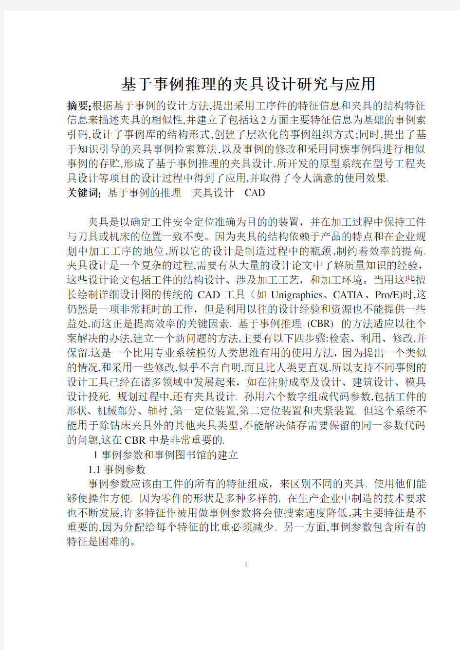
事例索引码的结构如图1所示。
1—夹具类型;6—工件重量;11—夹紧模型;
2—工件形状;7—工件刚度;12—夹具体;
3—工件材料;8—加工内容;13—其他;
4—批量;9—过程所有物;14到16—事例识别码;
5—工件比例;10—定位模型;
图1 事例索引码的结构
1.2事例库
事例库由许多预定义的事例组成。事例的描述是基于事例推理的最重要的问题之一。所以由索引码复合。
1.3 事例的层次化
夹具的结构相似被认为是整个夹具,成分和内容相似。所以,整个夹具事例库,成分事例库,夹具的成分事例库形成相同。整个夹具的设计资料通常是由工件资料和工件加工资料组成,这就意味着夹具的设计应满足特别功能的需求.全部夹具事例是由功能成分组成,它是用功能成分的名字和数字来进行描述的。成分事例代表成员(成分功能和其他结构成分,主要驱动参数,数字,和它们的约束关系)。成分事例(夹具的最低层)是功能成分和和其他成分的结构。
在现代夹具设计中有很多参数化准件和普通非标准件。所以成分事例图书馆应记录特殊参数和保持它们的方法。
2事例修改的策略
在基于事例的夹具设计中,最重要的是相似点的修改,这样能有助于获得最相似的事例,以及缩短适应时间。根据夹具设计的需求,事例修改的策略使最接近的事例方法和知识指导结合起来。首先在深度上查找,然后在宽度上;知识指导策略意味着在来自客观事物根源的知识规则上查找,这就要首先查找固定类型,然后查找工件的形状,第三查找定位方法。例如,如果事例索引码包括夹具类型的磨削夹具,就只查找所有的磨削夹具,然后查找工件形状的盒子,第三查找一个平面两个销的定位方法。如果没有合适的,就查找深度标点,然后回到最上层,然后再找所有与宽度相关的事例。
修改方法:
1)根据夹具事例库的事例索引信息,查找有关事例库。
2)将事例索引码与事例库的每个事例码匹配,然后计算相似尺寸的价值。
3)整理相似尺寸的次序,最大的架子是最类似的事例。
两个事例之间的相似点是基于两个事例特征之间的相似点。相似点尺寸的计算依靠特征的类型。相似点的价值可以通过数字化的价值来计算,例如比较重量分别是50kg 和20kg的工件。非数字化的价值也能计算,例如,现在前13位索引码都是非数字化的价值。一个夹具的相似尺寸的计算公式如下:
其中S表示通用夹具的相似尺寸,n表示索引特性数,表示每个特性的重量,
表示事例库中特性和相关夹具的特性的相似尺寸。同时,
,数值计算如下:
其中表示第i个特征的索引特性值,表示事例库中第j个事例的第i个特
征的特性值。
所以有两种方法选择相似夹具。一个方法是建立数值。如果通用事例的相似尺寸值比给定的数值小,这些事例就不能选来作相似事例。事例库最初建立的时候,只有一些事例,数值可以建小一点。如果有大量的相似事例,数值就应该建的大一些。另外一个方法是只建立相似事例的数字(例如10),这是类型单里相似尺寸的最大值。
3 事例的修改和存储
3.1事例的修改
夹具设计中相似事例的修改包括以下三个阶段:
1)成分的替代
2)保持形式不变,调整成分的特性
3)模型重新设计
如果夹具的成分是普通的物品,它们能通过使用工具被修改,代替以及删除,这些已经被设计好了。
3.2事例的存储
在将一个新的事例保存到事例库之前,设计者必须考虑保存是否有价值。如果这个事例不能增加系统的知识,就没有必要把它保存到事例库里。如果它有价值的话,设计者在保存之前必须分析一下,看看这个事例是否作为标准事例或参考事例被存储了。一个标准事例是一个描述同族事例主要特征的标准。一个同族事例是有事例库中索引码前13位相同而最后三位不同的那些事例组成的。一个标准事例的最后三位通常是“000”。一个参考事例属于同族标准事例,
最后三位用不同数字区分。
从被解释的概念中,可采用以下方法:
1)如果一个新的事例和任何一个存在的事例族一致,和一个存在的标准事例的前13位数相同,那么这个事例就不能存储因为已经这种标准事例了。或者只能作为一个参考事例保存(最后三位不是“000”,而且和其它的不一样)在事例库中。
2)如果一个新的事例和任何一个存在的事例族一致,并且被认为代替这个事例族要比以前的标准事例好,那么这个标准事例就被这个新的事例代替,以前的标准事例作为一个参考事例保存。
3)如果一个新的事例和任何一个存在的事例族不一致,一个新的事例族将会自动产生,并作为标准事例保存到事例库中。
4夹具设计中基于事例推理的过程
根据夹具设计的特性,夹具设计的基本信息,例如夹具的名字,零件,生产和设计者等等,必须先输入。然后,输入或设计工件的模型。输入有关工件的细节信息,建立事例索引码,然后CBR开始依靠相似尺寸查找相似事例,选出最相似的事例。如果需要的话,事例要满足通用性设计,再存储到事例库中。程序流程图如图2所示
图2 基于事例推理的夹具设计流程图
5基于事例推理的夹具设计说明
这是一个工件如图3所示。材料是45钢,底座,形状为块状,生产批量为中批等。需要设计成一个用来旋转孔的旋转夹具。
图3 需要设计夹具的一个工件
(最大尺寸80mmx49mmx22mm)
工件的特征值,属性值,事例索引码和重量在表1中列出。
表1 工件的事例索引码和重量
特征名称特性值索引码重量
夹具类型车床夹具 1 100
工件形状块状9 90
工件材料中碳钢 3 70
批量中批 2 60
工件比例小 5 60
工件重量轻 5 60
工件刚度硬度强 1 60
加工内容孔 3 80
程序要求完成加工 3 70
定位方法三个平面 1 100
夹紧方法不确定?90
夹具体复合 4 80
其他没有0 60
通过查找和计算相似点,最相似的事例的事例索引码是19325513321402000,细节信息在表2中列出。
表2 最相似事例的事例索引码
特征名称特性值索引码
夹具类型车床夹具 1
工件形状块状9
工件材料中碳钢 3
批量中批 2
工件比例小 5
工件重量轻 5
工件刚度硬度强 1
加工内容孔 3
程序要求完成加工 3
定位方法三个平面 1
夹紧方法不确定?
夹具体复合 4
其他没有0
相似点的计算如下:
所以夹具的相似尺寸值是0.806,这是在事例库中用于设计的最相似的事例,最相似的事例的结构如图4所示
图4 最相似的夹具
当成分替代,修改定位模型和夹紧模型,以及调节相关尺寸之后,新的夹具被设计出来,图形如图6所示
图5 需要设计的新夹具
因为在事例库中没有相似夹具,新夹具被储存到事例库中。事例索引码是19325523311402000。
6 结论
基于事例推理,作为一个问题解决的方法,是一个比模仿人类思想的专业系统更有效的方法,已经在很多难获取知识的领域里得到发展。基于事例推理的优点如下:它和人类的思想很相似;一个事例库通过保存新事例获得自学能力,它比有惯例库更快更容易,它可以更好的传递和解释新的知识,这和惯例库有
很大的不同。基于事例推理中提出的一个夹具设计的框架已经被实行了,使用的是支持基础数据的VC++,UG电脑绘图软件。这个框架也已经和普通成分库和典型夹具库结合起来。这个发展的标准系统,用于航空项目,帮助夹具设计者提高设计效率和重新使用先前的设计资源。
Application and development
Of case based reasoning in fixture design
Abstract: Based on the case based designing (CBD) methodology, the fixture similarity is in two respects: the function and the structure information. Then, the computer aided fixture design system is created on case based reasoning (CBR),in which the attributes of the main features of work piece and structure of fixture as case index code are designed for the retrieve of the similar cases, and the structure and hierarchical relation of case library are set up for store. Meanwhile, the algorithm based on the knowledge guided in the retrieve of the similar cases, the strategy of case adapt at ion and case storage in which the case indent if cat ion number is used to distinguish from similar cases are presented. The application of the system in some projects improves the design efficiency and gets a good result .
Keywords: case based reasoning ;fixture design; computer aided design(CAD)
Fixtures are devices that serve as the purpose of holding the work piece securely and accurately, and maintaining a consistent relationship with respect to the tools while machining. Because the fixture structure depends on the feature of the product and the status of the process planning in the enterprise, its design is the bottleneck during manufacturing, which restrains to improve the efficiency and lead-time. And fixture design is a complicated process, based on experience that needs comprehensive qualitative knowledge about a number of design issues
including work piece configuration, manufacturing processes involved, and machining environment. This is also a very time consuming work when using traditional CAD tools (such as Epigraphic, CATIA or Pro/E), which are good at performing detailed design tasks, but provide few benefits for taking advantage of the previous design experience and resources, which are precisely the key factors in improving the efficiency. The methodology of case based reasoning (CBR) adapts the solution of a previously solved case to build a solution for a new problem with the following four steps: retrieve, reuse, revise, and retain [1]. This is a more useful method than the use of an expert system to simulate human thought because proposing a similar case and applying a few modifications seems to be self explanatory and more intuitive to humans .So various case based design support tools have been developed for numerous areas[2-4], such as in injection molding and design, architectural design, die casting die design, process planning, and also in fixture design. Sun used six digitals to compose the index code that included work piece shape, machine portion, bushing, the 1st locating device, the 2nd locating device and clamping device[5]. But the system cannot be used for other fixture types except for drill fixtures, and cannot solve the problem of storage of the same index code that needs to be retained, which is very important in CBR[6].
1 Construction of a Case Index and Case Library
1.1 Case index
The case index should be composed of all features of the work piece, which are distinguished from different fixtures. Using all of them would make the
operation in convenient. Because the forms of the parts are diverse, and the technology requirements of manufacture in the enterprise also develop continuously, lots of features used as the case index will make the search rate slow, and the main feature unimportant, for the reason that the relative weight which is allotted to every feature must diminish. And on the other hand, it is hard to include all the features in the case index.
Therefore, considering the practicality and the demand of rapid design, the case index includes both the major feature of the work piece and the structure of fixture. The case index code is made up of 16 digits: 13 digits for case features and 3 digits for case identification number.
The first 13 digits represent 13 features. Each digit is corresponding to an attribute of the feature, which may be one of“*”, “?”, “1”, “2”,…,“A”,“B”,…,“Z”,…, etc. In which, “*”means anyone, “?”uncertain, “0”nothing.
The system rules: fixture type, work piece shape, locating model cannot be “*”or“?”. When the system is designed, the attribute information of the three items does not have these options, which means the certain attribute must be selected.
The last three digits are the case identification number, which means the 13 digits of the case feature are the same, and the number of these three digits is used for distinguishing them.
The system also rules: “000”is a prototype case, which is used for retrieval, and other cases are “001”,“002”,…,which are used for reference cases to be
searched by designers. If occasionally one of them needs to be changed as the prototype case, first it must be required to apply to change the one to “000”, and the former is changed to referential case automatically.
The construction of the case index code is shown in Fig.1.
1.2 Case library
The case library consists of lots of predefined cases. Case representation is one of the most important issues in case based reasoning. So compounding with the index code,.
1.3 Hierarchical form of Case
The structure similarity of the fixture is represented as the whole fixture similarity, components similarity and component similarity. So the whole fixture case library, components case library, component case library of fixture are formed correspondingly. Usually design information of the whole fixture is composed of work piece information and work piece procedure information, which represent the fixture satisfying the specifically designing function demand. The whole fixture case is made up of function components, which are described by the function components’names and numbers. The components case represents the members.
(function component and other structure components,main driven parameter, the number, and their constrain relations.) The component case (the lowest layer of the fixture) is the structure of function component and other components. In the modern fixture design there are lots of parametric standard parts and common non standard parts. So the component case library should record the specification parameter and the way in which it keeps them.
2 Strategy of Case Retrieval
In the case based design of fixtures ,the most important thing is the retrieval of the similarity, which can help to obtain the most similar case, and to cut down the time of adaptation. According to the requirement of fixture design, the strategy of case retrieval combines the way of the nearest neighbor and knowledge guided. That is, first search on depth, then on breadth; the knowledge guided strategy means to search on the knowledge rule from root to the object, which is firstly searched by the fixture type, then by the shape of the work piece, thirdly by the locating method. For example, if the case index code includes the milling fixture of fixture type, the search is just for all milling fixtures, then for box of work piece shape, the third for 1plane+ 2pine of locating method. If there is no match of it, then the search stops on depth, and returns to the upper layer, and retrieves all the relative cases on breadth.
Retrieval algorithms:
1)According to the case index information of fixture case library, search the relevant case library;
2)Match the case index code with the code of each case of the case library, and
calculate the value of the similarity measure;
3)Sort the order of similarity measure, the biggest value, which is the most analogical case.
Similarity between two cases is based on the similarity between the two cases. features. The calculation of similarity measure depends on the type of the feature. The value of similarity can be calculated for numerical values, for example, compare Work piece with the weight of 50kg and 20kg. The value can also be calculated between non numerical values, for example, now the first 13 digits index code is all non numerical values. The similarity measure of a fixture is calculated as follows:
where S is the similarity measure of current fixture, n is the number of the
index feature, is the weight of each feature, is the similarity
measure of the attribute of the i2th feature with the attribute of relative
feature of the j-th case in the case library. At the same time, , the value counts as follows:
.
Where is the value of the index attribute of the i-th feature, and is the value of attribute of the relative i-th feature of the j-th case in case library.
So there are two methods to select the analogical fixture. One is to set the value. If the values of similarity measure of current cases were less than a given value, those cases would not be selected as analogical cases. When the case library is initially set up, and there are only a few cases, the value can be set smaller. If there are lots of analogical cases, the value should get larger. The other is just to set the number of the analogical cases (such as10), which is the largest value of similarity measure from the sorted order.
3 Case adaptation and Case Storage
3.1 Case adaptation
The modification of the analogical case in the fixture design includes the following three cases:
1) The substitution of components and the component;
2) Adjusting the dimension of components and the component while the form remains;
3) The redesign of the model.
If the components and component of the fixture are common objects, they can be edited, substituted and deleted with tools, which have been designed.
3.2 Case storage
Before saving a new fixture case in the case library, the designer must consider whether the saving is valuable. If the case does not increase the knowledge of the system, it is not necessary to store it in the case library. If it is valuable, then the designer must analyze it before saving it to see whether the case is stored as a prototype case or as reference case. A prototype case is a representation that can describe the main features of a case family. A case family consists of those cases whose index codes have the same first 13 digits and different last three digits in the case library. The last three digits of a prototype case are always “000”. A reference case belongs to the same family as the prototype case and is distinguished by the different last three digits.
From the concept that has been explained, the following strategies are adopted:
1) If a new case matches any existing case family, it has the same first 13 digits as an existing prototype case, so the case is not saved because it is represented well by the prototype case. Or is just saved as a reference case (the last 3 digits are not “000”, and not the same with others) in the case library.
2) If a new case matches any existing case family and is thought to be better at representing this case family than the previous prototype case, then the prototype case is substituted by this new case, and the previous prototype case is saved as a reference case.
3) If a new case does not match any existing case family, a new case family will be generated automatically and the case is stored as the prototype case in the case
library.
4 Process of CBR in Fixture Design
According to the characteristics of fixture design, the basic information of the fixture design such as the name of fixture, part, product and the designer, etc. must be input first. Then the fixture file is set up automatically, in which all components of the fixture are put together. Then the model of the work piece is input or designed. The detailed information about the work piece is input, the case index code is set up, and then the CBR begins to search the analogical cases, relying on the similarity measure, and the most analogical case is selected out. If needed, the case is adapted to satisfy the current design, and restored into the case library. The flowchart of the process is shown in Fig.3.
5 Illustrating for Fixture Design by CBR
This is a work piece (seeFig.4). Its material is 45# steel. Its name is seat. Its
shape is block, and the product batch size is middle, etc. A fixture is turning fixture that serves to turn the hole, which needs to be designed.
The value of feature, attribute, case index code and weight of the work piece is show n in Tab.2.
Through searching, and calculating the similarity, the case index code of the
most similar case is 19325513321402000, and the detailed information is show n in Tab. 3.
The similarity is calculated as follows:
So the value of similarity measure of the fixture which needs to be designed with the most analogical case in case library is 0.806, and the structure of the most analogical case is shown in Fig.5.
机械毕业设计英文外文翻译71车床夹具设计分析
附录A Lathe fixture design and analysis Ma Feiyue (School of Mechanical Engineering, Hefei, Anhui Hefei 230022, China) Abstract: From the start the main types of lathe fixture, fixture on the flower disc and angle iron clamp lathe was introduced, and on the basis of analysis of a lathe fixture design points. Keywords: lathe fixture; design; points Lathe for machining parts on the rotating surface, such as the outer cylinder, inner cylinder and so on. Parts in the processing, the fixture can be installed in the lathe with rotary machine with main primary uranium movement. However, in order to expand the use of lathe, the work piece can also be installed in the lathe of the pallet, tool mounted on the spindle. THE MAIN TYPES OF LATHE FIXTURE Installed on the lathe spindle on the lathe fixture
曲轴的加工工艺及夹具设计外文翻译
毕业设计 外文翻译 题目曲轴的加工工艺及夹具设计学院航海学院 专业轮机工程 学生佟宝诚 学号 10960123 指导教师彭中波 重庆交通大学 2014年
Proceedings of IMECE2008 2008 ASME International Mechanical Engineering Congress and Exposition October 31-November 6, 2008, Boston, Massachusetts, USA IMECE2008-67447 MULTI-OBJECTIVE SYSTEM OPTIMIZATION OF ENGINE CRANKSHAFTS USING AN INTEGRATION APPROACH Albert Albers/IPEK Institute of Product Development University of Karlsruhe Germany Noel Leon/CIDyT Center for Innovation andDesign Monterrey Institute of Technology,Mexico Humberto Aguayo/CIDyT Center forInnovation and Design, Monterrey Institute ofTechnology, Mexico Thomas Maier/IPEK Institute of Product Development University of Karlsruhe Germany ABSTRACT The ever increasing computer capabilities allow faster analysis in the field of Computer Aided Design and Engineering (CAD & CAE). CAD and CAE systems are currently used in Parametric and Structural Optimization to find optimal topologies and shapes of given parts under certain conditions. This paper describes a general strategy to optimize the balance of a crankshaft, using CAD and CAE software integrated with Genetic Algorithms (GAs) via programming in Java. An introduction to the groundings of this strategy is made among different tools used for its implementation. The analyzed crankshaft is modeled in commercial parametric 3D CAD software. CAD is used for evaluating the fitness function (the balance) and to make geometric modifications. CAE is used for evaluating dynamic restrictions (the eigenfrequencies). A Java interface is programmed to link the CAD model to the CAE software and to the genetic algorithms. In order to make geometry modifications to
基于solidworks机床夹具设计外文翻译详解
2604130359 CNC Cutting Technology Review Numerical control high speed cutting technology (High Speed Machining, HSM, or High Speed Cutting, HSC), is one of the advanced manufacturing technology to improve the machining efficiency and quality, the study of related technology has become an important research direction of advanced manufacturing technology at home and abroad. China is a big manufacturing country, in the world of industry transfer to accept the front instead of back-end of the transfer, to master the core technology of advanced manufacturing, or in a new round of international industrial structure adjustment, our country manufacturing industry will further behind. Imminent research on the theory and application of advanced technology. 1, high-speed CNC machining meaning High speed cutting theory put forward by the German physicist Carl.J.Salomon in the last century and early thirty's. He concluded by a lot of experiments: in the normal range of cutting speed, cutting speed if the increase, will cause the cutting temperature rise, exacerbating the wear of cutting tool; however, when the cutting speed is increased to a certain value, as long as more than the inflection point, with the increase of the cutting speed, cutting temperature can not rise, but will decline, so as long as the cutting speed is high enough, it can be solved very well in high cutting temperature caused by tool wear is not conducive to the cutting problem, obtained good processing efficiency. With the development of manufacturing industry, this theory is gradually paid more attention to, and attracted a lot of attention, on the basis of this theory has gradually formed the field of high-speed cutting technology of NC, relatively early research on NC High-speed Machining Technology in developed countries, through the theoretical basis of the research, basic research and applied research and development application, at present applications have entered the substantive stage in some areas. The high-speed cutting processing category, generally have the following several kinds of classification methods, one is to see that cutting speed, cutting speed over conventional cutting speed is 5-10 times of high speed cutting. Also has the scholar to spindle speed as the definition of high-speed processing standards, that the spindle speed is higher than that of 8000r\/min for high speed machining. And from the machine tool spindle design point of view, with the product of DN diameter of spindle and spindle speed, if the value of DN to (5~2000) * 105mm.r\/min, is considered to be of high speed machining. In practice, different processing methods, different materials, high speed cutting speed corresponding to different. Is generally believed that the turning speed of (700~7000) m\/min, milling speed reaches m\/min (300~6000), that is in the high-speed cutting. In addition, from the practical considerations, high-speed machining concept not only contains the high speed cutting process, integration and optimization also contains the process of cutting, is a
夹具设计英文文献
A review and analysis of current computer-aided fixture design approaches Iain Boyle, Yiming Rong, David C. Brown Keywords: Computer-aided fixture design Fixture design Fixture planning Fixture verification Setup planning Unit design ABSTRACT A key characteristic of the modern market place is the consumer demand for variety. To respond effectively to this demand, manufacturers need to ensure that their manufacturing practices are sufficiently flexible to allow them to achieve rapid product development. Fixturing, which involves using fixtures to secure work pieces during machining so that they can be transformed into parts that meet required design specifications, is a significant contributing factor towards achieving manufacturing flexibility. To enable flexible fixturing, considerable levels of research effort have been devoted to supporting the process of fixture design through the development of computer-aided fixture design (CAFD) tools and approaches. This paper contains a review of these research efforts. Over seventy-five CAFD tools and approaches are reviewed in terms of the fixture design phases they support and the underlying technology upon which they are based. The primary conclusion of the review is that while significant advances have been made in supporting fixture design, there are primarily two research issues that require further effort. The first of these is that current CAFD research is segmented in nature and there remains a need to provide more cohesive fixture design support. Secondly, a greater focus is required on supporting the detailed design of a fixture’s physical structure. 2010 Elsevier Ltd. All rights reserved. Contents 1. Introduction (2) 2. Fixture design (2) 3. Current CAFD approaches (4) 3.1 Setup planning (4) 3.1.1 Approaches to setup planning (4) 3.2 Fixture planning (4) 3.2.1 Approaches to defining the fixturing requirement (6) 3.2.2 Approaches to non-optimized layout planning (6) 3.2.3 Approaches to layout planning optimization (6) 3.3 Unit design (7) 3.3.1 Approaches to conceptual unit design (7)
夹具设计--翻译
基于事例推理的夹具设计研究与应用 摘要:根据基于事例的设计方法,提出采用工序件的特征信息和夹具的结构特征信息来描述夹具的相似性,并建立了包括这2方面主要特征信息为基础的事例索引码,设计了事例库的结构形式,创建了层次化的事例组织方式;同时,提出了基于知识引导的夹具事例检索算法,以及事例的修改和采用同族事例码进行相似事例的存贮,形成了基于事例推理的夹具设计.所开发的原型系统在型号工程夹具设计等项目的设计过程中得到了应用,并取得了令人满意的使用效果. 关键词: 基于事例的推理夹具设计CAD 夹具是以确定工件安全定位准确为目的的装置,并在加工过程中保持工件与刀具或机床的位置一致不变。因为夹具的结构依赖于产品的特点和在企业规划中加工工序的地位,所以它的设计是制造过程中的瓶颈,制约着效率的提高. 夹具设计是一个复杂的过程,需要有从大量的设计论文中了解质量知识的经验,这些设计论文包括工件的结构设计、涉及加工工艺,和加工环境。当用这些擅长绘制详细设计图的传统的CAD工具(如Unigraphics、CATIA、Pro/E)时,这仍然是一项非常耗时的工作,但是利用以往的设计经验和资源也不能提供一些益处,而这正是提高效率的关键因素. 基于事例推理(CBR) 的方法适应以往个案解决的办法,建立一个新问题的方法,主要有以下四步骤:检索、利用、修改,并保留.这是一个比用专业系统模仿人类思维有用的使用方法,因为提出一个类似的情况,和采用一些修改,似乎不言自明,而且比人类更直观.所以支持不同事例的设计工具已经在诸多领域中发展起来,如在注射成型及设计、建筑设计、模具设计投死, 规划过程中,还有夹具设计. 孙用六个数字组成代码参数,包括工件的形状、机械部分、轴衬,第一定位装置,第二定位装置和夹紧装置. 但这个系统不能用于除钻床夹具外的其他夹具类型,不能解决储存需要保留的同一参数代码的问题,这在CBR中是非常重要的. 1事例参数和事例图书馆的建立 1.1事例参数 事例参数应该由工件的所有的特征组成,来区别不同的夹具. 使用他们能够使操作方便. 因为零件的形状是多种多样的, 在生产企业中制造的技术要求也不断发展,许多特征作被用做事例参数将会使搜索速度降低,其主要特征是不重要的,因为分配给每个特征的比重必须减少. 另一方面,事例参数包含所有的
机械设计工艺夹具设计开题报告(含文献综述、外文翻译)
毕业设计开题报告 (含文献综述、外文翻译) 题目 姓名 学号 班级 专业机械设计制造及其自动化 学院机械工程学院 指导教师(职称)
1. 获得广泛的应用,1.1 1.2 选题意义 2.设计内容 2.1 主要设计内容 …………………………… 2.2 拟解决的关键问题 …………………………… 3.设计的方法及措施 3.1 可行性分析 ……………………………
3.2 方法及措施 …………………………… 4.预期设计成果 …………………………… 5.设计工作进度计划 本毕业设计的阶段划分与进度安排如下: 第一阶段:第七学期第10~12周(2010.11.1~2010.11.19),查阅文献和撰写 第二阶段:第七学期第13 第三阶段:第八学期第1~ ……….; ……; ……….; ……….; ……….; 第六阶段:第八学期第10~12周(2011…..~2011…..),整理和撰写设计论文,形成终稿,送审、修改、并装订。
1. 获得广泛的应用,分子合成技术,……2.研究方向 2.1 2.1.1 机械结构设计
参考文献(含开题报告和文献综述) [1] 蒋继红, 虞贤颖, 王效岳. 塑料成型模具典型结构图册 出版社, 2006. [2] 朱祖超. ARKKIO A. Determination [S]. 北京: 中国标准出版社, 1996. 期刊 [序号] 主要责任者. 文献题名[J]. 刊名, 出版年份,卷号(期号): 起止页码. 专著 [序号] 主要责任者. 文献题名[M]. 其他责任者. 出版地: 出版者, 出版年. 国际、国家标准 [序号] 标准代号, 标准名称[S]. 出版地: 出版者, 出版年. 学位论文 [序号] 主要责任. 文献题名[D]. 保存地: 保存单位, 年份.
夹具设计-英外文翻译
基于案例学习的夹具设计 石奇,杨海成,李元, 国家重点实验室计算机辅助设计/计算机辅助制造,西北工业大学 西安710072,中国 【摘要】:夹具是生产活动中不可或缺的一部分。本文提出了一个基于案例推理的夹具设计系统。提出的一种新方法的基础上,案例的情况表示是由工件加工特征的知识,处理功能知识和夹具特征知识构成。运行原型系统的知识表示方法,使用的情况下,是一个更好的方式来改造和解释的设计知识。 【关键词】:基于案例的推理,夹具设计,知识表示,案例检索 1.引言 工件夹持装置用于在大部分的制造操作,如机加工,装配,检查等。作为制造规划的一部分,夹具设计的制造可以是一个主要因素。夹具设计是一个可以在制造,交货时间和产品的成本上的主要贡献者。由于种类繁多的零部件和制造业务,夹具设计的过程变得更加复杂和不加控制。此外,设计一个夹具在很大程度上依赖于专业设计师和经验,以及生产,加工,技术,和零件的数据。计算机辅助夹具设计(CAFD)技术的CAD/ CAM集成的一部分已经得到开发。如今,CAFD柔性制造系统(FMS)和计算机集成制造系统(CIMS)在其中起着重要的作用。在夹具设计中采用计算机必须考虑的第一件事情是建立一个合适的设计规划模型。同时也必须建立一个成功的夹具设计系统的知识表示方法,来用于设计和设计师的经验。 相对于经典的以规则为基础的推理和基于模型的推理,基于案例的推理(CBR)尝试使用以前的情况下,从案例库和适应的解决方案中类似的问题,根据新形势下的参数,解决新问题。多以规则为基础的推理或基于模型的推理这种方法的主要优点是将减少规则或模型,设计中采用的多是比较复杂的知识。解决机械设计问题的方法占有重要的好处。有系统已设计系统CBR文献记载。一个系统,称为DEJA VU使用基于案例的推理,以协助机械设计。另一种的系统称为CADSYM是一个混合的情况为基础的设计模型,它建议将特定领域知识。在本文中,案例主要来阐述专业知识和设计经验。夹具设计的基础上灯具功能的情况下表示的方法的建议。第2节介绍了基于案例推理的概念。第3节提供夹具的
夹具设计文献综述
ZQ350减速器传动轴键槽铣夹具设计文献综述机械电子工程专业机械A1321班李雪指导老师:张玉英 前言 夹具最早出现在18世纪后期,随着人们生活水平的提高,科学的不断发展进步,从辅助工具慢慢发展为门类齐全的加工装备的夹具,在机械加工焊接,热处理,装配中有着不可取代的地位,在机械加工过程中,为了保证加工精度,固定工件,使之占在正确位置以接受加工或检测的工艺装备称为机床夹具。其组成包括定位元件、夹紧装置、夹具与机床之间的连接元件、对刀或导向元件、其他装置或元件、夹具体。使用机床夹具可以保证工件的加工精度,减少辅助工时,大幅提高生产效率,还能扩大机床使用范围,实现“一机多能”。机床夹具在机械加工中起着重要的作用,它直接影响着机械加工的质量、生产效率和成本。夹具不仅用于金属切削加工,还可以应用在检验、装配、焊接零件、生产线制造等过程中,是机械加工过程中必不可少的工艺装备。机床夹具设计的效率和质量对产品的上市时间和质量的影响很大,在产品生产制造中具有重要的意义,各个企业都在不断地增加人力和物力来加快其设计和生产速度。 机床夹具的功能 (1)保证加工精度工件加工过程通过机床夹具进行定位、加紧,以保证加工表面稳定的位置精度。 (2)缩短辅助时间,提高生产率夹具的使用,可以减少划线、找正、对刀等辅助时间,多件,多工位的夹具及气动、液动的夹紧装置能进一步减少辅助时间,提高生产率。 (3)扩大了机床的使用范围有的机床夹具实质上对机床进行了局部改造,扩大了原来机床的功能和使用范围。 (4)降低了对工人技术水平的要求和减轻工人的劳动强度,保证生产安全。夹具的发展历程,大约可以分为三个阶段: 第一个阶段主要表现在夹具与人的结合上,这是夹具主要是作为人的单纯的辅助工具,使得加工过程进一步提高效率和趋于完善.这一阶段使用夹具旨在提高生产率。 第二阶段,夹具成为人与机床之间的桥梁,夹具的机能发生变化,它主要用于工件的定位和夹紧。 第三阶段表现为夹具与机床的结合,夹具作为机床的一部分,成为机械加工中不可缺少的工艺装备,夹具是实现工艺的手段之一。 夹具分类 随着机械制造业的不断发展,机床夹具的种类日趋繁多,常可按照应用范围、使用机床、夹具动力源来分类。 (1)按夹具的应用范围分类 根据夹具在不同生产类型中的通用特性,机床夹具可分为通用夹具、专用夹具、可调整夹具和组合夹具等。
汽车焊接夹具设计中英文对照外文翻译文献
汽车焊接夹具设计中英文对照外文翻译文献(文档含英文原文和中文翻译)
汽车焊接夹具的设计 1摘要 依据车体焊装线夹具设计理论,对各工位焊接夹具及其焊装总线进行规划、设计,之后进行夹具建模、装配,插入焊钳确定其数量、型号及判断其可达性,最终设计出符合要求的焊接夹具。 关键词:焊接部件;基础;夹紧;位置 1.介绍 装配和焊接夹具在汽车车身装配和焊接生产线与生产制造优质的汽车设备息息相关。焊装夹具,是焊接工艺的重要组成部分。装配和焊接夹具除了是完成这个过程中零部件装配的途径和定位,同时在生产线上也作为一个测试和校准程序,完成检测焊接配件和焊接质量的任务。因此焊装夹具的设计和制造,直接影响焊接过程中汽车的生产能力和产品质量。汽车焊装夹具是保证其制造质量、缩短其制造周期的重要手段。因此,正确理解焊装夹具设计要点,改善和提高焊装夹具的设计手段和设计水平,并提高夹具的调整和验证水平等三方面都是必不可少的,也是汽车制造公司在激烈的竞争中得以生存所必须解决的问题。
汽车的风格不同,焊接夹具的形状,因而有着很大的不同,但在设计、制造和调整都是共同的,可以借鉴采用。 2.焊接夹具的结构设计 焊接夹具的结构设计,确保该夹具有良好的操作方便性、装夹定位的可靠性。焊装夹具的制造商也很容易集成的调整,以保证结构各部分的表面应该允许足够的空间用于调整,以确保立体可调。当然,在确保焊接夹具质量准确性的前提下,焊接夹具的结构应尽可能简单。夹具设计通常是夹具上全部元件的位置都是直接根据设计基准确定的,最终保证制造出合格的焊接工装结构。根据作业高度可初步决定夹具底板的高度,即夹具固定位置的高度。焊接夹具设计首先要考虑夹紧方式,一般有手动和气动两种,手动夹紧一般适合于小件、外协件、小批量工件焊装,对于大型车体部件、规划于生产线内、自动化程度要求高的焊接夹具宜选用气动夹紧,汽车生产的一般采用气动夹紧,然后手工大批量夹紧可作为辅助夹紧。这样可以相应的降低成本。部分手动夹紧产品已拥有标准的型号和数量,需要时可以到市场购买即可。对于某些装置,规定采用气动夹紧,但如果直接使用气动夹紧,可能损坏的工件,所以,可以由人工先按地方,来提供一种气动夹紧力夹紧工件,这是手动-气动。该夹具夹紧系统是安装在一个大平台,所有固定在此保证焊接位置的焊接条件应符合设计尺寸的工件坐标系定位夹具,这牵涉到的基准。 3.装配和焊接夹具的基准和他们所选择的支撑面 3.1设计基准的确定 每个夹具必须具有固定坐标系统,在这个坐标系统, 它的支撑基础坐标尺寸应该支持工件以及坐标对应于同样的大小。所以在整个的焊装夹具系统
夹具设计英文文献翻译
讨论和分析现代计算机辅助夹具设计方法Iain 波以耳、Yiming Rong,戴维布朗关键字:计算机辅助夹具设计;夹具设计;夹具设计;夹具确认;装备设计;元件设计摘要现代市场是一个主要为满足消费者多样性需求的地方。为了种有效地回应这要求,制造业者确定他们的制造业拥有充分的柔性以满足他们迅速的生产发展的需要。夹具设计,是指使用夹具在制造过程中装夹工件,以便他们能被加工成满足设计规格的产品,是提高制造业柔性一个重要的有利因素。为了使有柔性的夹具成为可能,已经有相当程度的研究努力热衷于使用计算机辅助夹具设计(CAFD)工具和方法发展辅助夹具设计。这篇文献包含这些研究努力的讨论。超过七十五个CAFD 工具和方法在夹具设计方面被讨论并逐步实行计算机辅助和以其为基础的技术。讨论的主要结论是当已经被在辅助夹具设计方面有重要的进步时,主要地有两个需要进一步的努力的研究议题。第一,现在的CAFD 研究在本质上被分割,而且需要提供更多前后关联的夹具设计支持。第二,更多聚焦于一个夹具的自身结构的详细设计。2010 Elsevier 公司版权所有目录1. 介绍……………………………………………………………………………………………22. 夹具设计………………………………………………………………………………………23. 目前CAFD 的方
法.......................................................................................4 3.1 设置规划.............................................................................................4 3.1.1 满足要求的设置规划 (4) 3.2 夹具设计.............................................................................................4 3.2.1 达成定义夹具需求的方式...............................................................6 3.2.2 达成方法优化的布局规划...............................................................6 3.2.3 达成规划优化的方式 (6) 3.3 元件设计…………………………………………………………………………………7 3.3.1 达成概念上的元件设计的方式…………………………………………………7 3.3.2 达成详细的元件设计的方式……………………………………………………7 3.4 确认………………………………………………………………………………………8 3. 4.1 达成约束需求确认的方式………………………………………………………8 3.4.2
外文翻译---基于事例推理的夹具设计研究与应用
附录一 英文文献 Application and development Of case based reasoning in fixture design Fixtures are devices that serve as the purpose of holding the workpiece securely and accurately, and maintaining a consistent relationship with respect to the tools while machining. Because the fixture structure depends on the feature of the product and the status of the process planning in the enterprise, its design is the bottleneck during manufacturing, which restrains to improve the efficiency and leadtime. And fixture design is a complicated process, based on experience that needs comprehensive qualitative knowledge about a number of design issues including workpiece configuration, manufacturing processes involved, and machining environment. This is also a very time consuming work when using traditional CAD tools (such as Unigraphics, CATIA or Pro/E), which are good at performing detailed design tasks, but provide few benefits for taking advantage of the previous design experience and resources, which are precisely the key factors in improving the efficiency. The methodology of case based reasoning (CBR) adapts the solution of a previously solved case to build a solution for a new problem with the following four steps: retrieve, reuse, revise, and retain [1]. This is a more useful method than the use of an expert system to simulate human thought because proposing a similar case and applying a few modifications seems to be self explanatory and more intuitive to humans .So various case based design support tools have been developed for numerous areas[2-4], such as in injection molding and design, architectural design, die casting die design, process planning, and also in fixture design. Sun used six digitals to compose the index code that included workpiece shape, machine portion, bushing, the 1st locating device, the 2nd locating device and clamping device[5]. But the system cannot be used for other fixture types except for drill fixtures, and cannot solve the problem of storage of the same index code that needs to be retained, which is very important in CBR[6]. 1 Construction of a Case Index and Case Library 1.1 Case index
机械类外文翻译-基于事例推理的夹具设计研究与应用
外文翻译 基于事例推理的夹具设计研究与应用 摘要:根据基于事例的设计方法,提出采用工序件的特征信息和夹具的结构特征信息来描述夹具的相似性,并建立了包括这2方面主要特征信息为基础的事例索引码,设计了事例库的结构形式,创建了层次化的事例组织方式;同时,提出了基于知识引导的夹具事例检索算法,以及事例的修改和采用同族事例码进行相似事例的存贮,形成了基于事例推理的夹具设计.所开发的原型系统在型号工程夹具设计等项目的设计过程中得到了应用,并取得了令人满意的使用效果. 关键词: 基于事例的推理夹具设计CAD 夹具是以确定工件安全定位准确为目的的装置,并在加工过程中保持工件与刀具或机床的位置一致不变。因为夹具的结构依赖于产品的特点和在企业规划中加工工序的地位,所以它的设计是制造过程中的瓶颈,制约着效率的提高. 夹具设计是一个复杂的过程,需要有从大量的设计论文中了解质量知识的经验,这些设计论文包括工件的结构设计、涉及加工工艺,和加工环境。当用这些擅长绘制详细设计图的传统的CAD工具(如Unigraphics、CATIA、Pro/E)时,这仍然是一项非常耗时的工作,但是利用以往的设计经验和资源也不能提供一些益处,而这正是提高效率的关键因素. 基于事例推理(CBR) 的方法适应以往个案解决的办法,建立一个新问题的方法,主要有以下四步骤:检索、利用、修改,并保留.这是一个比用专业系统模仿人类思维有用的使用方法,因为提出一个类似的情况,和采用一些修改,似乎不言自明,而且比人类更直观.所以支持不同事例的设计工具已经在诸多领域中发展起来,如在注射成型及设计、建筑设计、模具设计投死, 规划过程中,还有夹具设计. 孙用六个数字组成代码参数,包括工件的形状、机械部分、轴衬,第一定位装置,第二定位装置和夹紧装置. 但这个系统不能用于除钻床夹具外的其他夹具类型,不能解决储存需要保留的同一参数代码的问题,这在CBR中是非常重要的. 1事例参数和事例图书馆的建立 1.1事例参数 事例参数应该由工件的所有的特征组成,来区别不同的夹具. 使用他们能够使操作方便. 因为零件的形状是多种多样的, 在生产企业中制造的技术要求也不断发展,许多特征作被用做事例参数将会使搜索速度降低,其主要特征是不
外文翻译---传动轴凸缘叉夹具的设计
附录 Fork Shaft Lugs fixture design Shell group processing according to the results of the machine and the group chosen type design group clamps, group clamps Realize that the group process, favorable to reasonable design, if no group clamps or design group clamps, convenient adjustment group processing can realize smoothly. The machine tool's fixture priority is to ensure machining accuracy, especially that of the machining process and positioning surface and processed surface between the position precision. After using this fixture mainly rely on precision tools and fixtures to ensure no longer rely on workers, the technical level. Second is to improve labor productivity, reduce cost, use fixture after is crossed, can reduce the auxiliary time, and easy to implement and multistage process. In modern times, is widely used in the machine tool's fixture etc mobile pneumatic, hydraulic clamping device, can make the assistant time do step. In the group technology group clamps are under the guidance of the principle, process and design for the implementation of the group, and special fixture Compared with the design group clamps, not for a certain parts of a process, but a group of some parts, Which group clamps to adapt to all parts of the group parts in a process of processing. Design of the key and difficult. When the workpiece in machine processing, the first to make workpiece in machine or a fixture in the correct position, it is the location, to prevent the process of cutting force or other forces destroyed the correct position, still must be fastened clamping workpiece, this is the clamping workpiece position and clamping workpiece installation process is called. Due to the workpiece position and orientation error, error called for clamping deformation and the error is called clamping error. Positioning error and clamping workpiece installation error named error. Because of this all parts for 21 kinds of workpieces, so the scheme is key to determine the fixture clamping deformation control at will The smallest. While clamping deformation control cannot rely on operators to realize in the past shell parts and machining by small and reliable clamping force to reduce clamping deformation, this will inevitably produce adverse product. In the introduction of domestic product technology at the same time, don't