Large-Scale Photonic Integrated Circuits
超快贝塞尔光束在硫化锌晶体表面制备纳米孔

270 μm。
关 键 词:硫化锌晶体;高深径比纳米孔;光子器件;高斯-贝塞尔光束
中图分类号:TN249
文献标志码:A
doi:10.37188/CO.2020-0101
1 Introduction
The mid-infrared photonics has attracted considerable attention because its wavebands cover thermal imaging bands, multiple atmospheric windows (3~5 μm and 8~14 μm) necessary for free space communication, as well as main absorption bands of most chemical and biological molecules. It is an inevitable trend for photonic integration to cut costs, improve performance and miniaturize special optical instruments, for example, micro-scale photonic circuits are manufactured in optical materials with a transparent window up to 20 μm. The application of integrated photonics has promoted the rapid development of optical communication technology and the expansion of applied wavelength from near infrared to middle and far infrared. However, the infrared window materials in medium and long wave bands are very limited, mainly including GaAs, GaP, ZnSe, ZnS, InSb, etc.[1-4]. Considering the optical and mechanical properties of these materials, ZnS crystal has become one of the most
Ultrahigh-bandwidth silicon photonic nanowire waveguides for on-chip

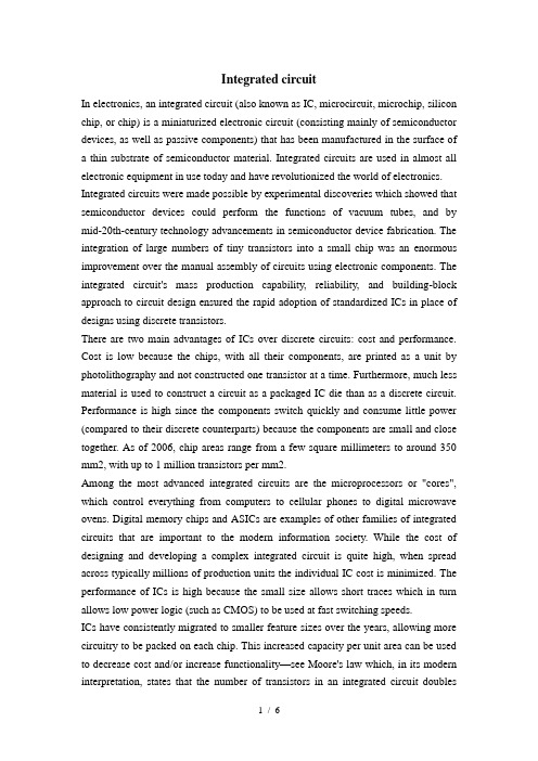
398IEEE PHOTONICS TECHNOLOGY LETTERS,VOL.20,NO.6,MARCH 15,2008Ultrahigh-Bandwidth Silicon Photonic NanowireWaveguides for On-Chip NetworksBenjamin G.Lee,Xiaogang Chen,Aleksandr Biberman,Xiaoping Liu,I-Wei Hsieh,Cheng-Yun Chou,Jerry I.Dadap,Fengnian Xia,William M.J.Green,Lidija Sekaric,Yurii A.Vlasov,Richard M.Osgood,Jr.,andKeren BergmanAbstract—An investigation of signal integrity in silicon pho-tonic nanowire waveguides is performed for wavelength-division-multiplexed optical signals.First,we demonstrate the feasibility of ultrahigh-bandwidth integrated photonic networks by transmit-ting a 1.28-Tb/s data stream (32wavelengths 40-Gb/s)through a 5-cm-long silicon wire.Next,the crosstalk induced in the highly confined waveguide is evaluated,while varying the number of wavelength channels,with bit-error-rate measurements at 10Gb/s per channel.The power penalty of a 24-channel signal is 3.3dB,while the power penalty of a single-channel signal is 0.6dB.Finally,single-channel power penalty measurements are taken over a wide range of input powers and indicate negligible change for launch powers of up to 7dBm.Index Terms—Multiprocessor interconnection,optical commu-nication,optical crosstalk,optical waveguides,wavelength-division multiplexing (WDM).I.I NTRODUCTIONRECENT advances in the density and complexity of pho-tonic integrated circuits (PICs)have enabled the viable integration of complete optical systems on a monolithic semi-conductor chip.As a result,PICs are envisioned as a plausible means of implementing on-chip and chip-to-chip intercon-nection networks [1],[2].Because of the high modulation rates and wavelength parallelism made available by optical transmission and wavelength-division-multiplexing (WDM),the large bandwidth demands of high-performance computingManuscript received September 27,2007;revised December 10,2007.The work of B.G.Lee,A.Biberman,and K.Bergman was supported by the National Science Foundation (NSF)under Grant CCF-0523771and Grant ECS-0725707.The work of X.Chen,X.Liu,I-W.Hsieh,C.-Y.Chou,J.I.Dadap,and R.M.Osgood,Jr.was supported by the Department of Defense (DoD)Small Business Technology Transfer (STTR)under Con-tract FA9550-05-C-1954and by the Air Force Office of Scientific Research (AFOSR)under Grant FA9550-05-1-0428.The work of F.Xia,W.M.J.Green,L.Sekaric,and Y .A.Vlasov was supported by the Defense Advanced Research Projects Agency (DARPA)under Grant N00014-04-C-0455.B.G.Lee,X.Chen, A.Biberman,X.Liu,I-W.Hsieh,C.-Y.Chou,R.M.Osgood,Jr.,and K.Bergman are with the Department of Elec-trical Engineering,Columbia University,New York,NY 10027USA (e-mail:benlee@;oliver@;ab2795@;xl2165@;ih2109@;cc2535@;osgood@;bergman@).J.I.Dadap is with the Department of Applied Physics and Applied Mathematics,Columbia University,New York,NY 10027USA (e-mail:dadap@).F.Xia,W.M.J.Green,L.Sekaric,and Y. A.Vlasov are with the IBM Thomas J.Watson Research Center,Yorktown Heights,NY 10598USA (e-mail:fxia@;wgreen@;lidija@;yvlasov@).Digital Object Identifier 10.1109/LPT.2008.916912systems can be met with integrated optics.Further advantages can be realized by implementing such a system in the com-plementary metal–oxide–semiconductor (CMOS)-compatible silicon-on-insulator platform [3].These benefits include ultra-compact footprint resulting from high index contrast,simple integration of electrical and optical components,and low-cost while at the same time extremely high-quality plex active and passive components have been envisioned and successfully fabricated in this material system [3]–[5].An equally important consideration,however,is the performance of the interconnection medium:the waveguide or photonic wire .High-bandwidth WDM transmission schemes have been demonstrated in III–V materials without emphasizing the importance of the photonic waveguide,and without offering compatibility with the CMOS electronics platform [6],[7].Here,we confirm that the low-loss silicon-wire-waveguide technology can be used both for on-chip networks and for chip-to-chip networks,where off-chip bandwidth is crucial.In this letter,we investigate the suitability of silicon photonic wires for carrying ultrahigh-bandwidth WDM data streams.Our central result is to demonstrate the successful transmission of a 1.28-Tb/s stream through a 5-cm-long wire waveguide.The aggregate data rate,composed of 32wavelengths,each mod-ulated at 40-Gb/s,is the largest reported in a silicon photonic wire to date [8],[9].Moreover,considering the area of conven-tional semiconductor dice (typically about 1cm ),this length is sufficient to route a signal anywhere on the die,regardless of the network topology or routing scheme.Additionally,we eval-uate the interchannel crosstalk induced by nonlinearities in the photonic wire with bit-error-rate (BER)measurements.These results,made possible by the recent improvements in the design and fabrication of the low-loss silicon wires,represent a signifi-cant step toward developing a complete toolbox for PIC design.II.E XPERIMENTAL S ETUP AND W A VEGUIDE D EVICE The experimental setup [Fig.1(a)]for the BER measure-ments employs 24continuous-wave communications lasers with outputs combined by a 32-channel multiplexer with 100-GHz channel spacing.The laser wavelengths are located on theITU -band,comprising channels C22–C32,C35–C38,and C43–C51.ALiNbO modulator encodesapseu-dorandom bit sequence onto each lightwave at 10Gb/s using the nonreturn-to-zero format.The signals are then decorrelated by 425ps/nm using 25km of single-mode fiber,which results in about 3.4bits of delay between adjacent wavelengths.The light is coupled in and out of the chip through tapered fibers [Fig.1(b)].Following the silicon chip,the signal is amplified1041-1135/$25.00©2008IEEELEE et al.:ULTRAHIGH-BANDWIDTH SILICON PHOTONIC NANOWIRE WA VEGUIDES FOR ON-CHIP NETWORKS399Fig.1.(a)Diagram of the experimental setup,(b)schematic of the fiber cou-pling and wire waveguide layout,and (c)scanning electron microscope (SEM)image of the silicon photonic wire cross section.by an erbium-doped fiber ampli fier (EDFA),after which some of the power is tapped for monitoring on an optical spec-trum analyzer (OSA).One wavelength channel is selected for measurement using a tunable filter,which is followed by an at-tenuator and a receiver module consisting of a p-i-n photodiode (PIN),transimpedance ampli fier (TIA),and limiting ampli fier (LA).The detected signal is evaluated with a communications signal analyzer (CSA)and a BER tester (BERT),which is synchronized directly to the pulse pattern generator (PPG)by a 10-GHz clock source.Polarization controllers (PCs)are used throughout.The setup for the 1.28-Tb/s demonstration employs 32chan-nels,C21(1560.61nm)through C52(1535.82nm),each modu-lated at 40Gb/s and decorrelated by 94ps/nm in 5.5km of fiber,resulting in about 3bits of delay between adjacent wavelengths.In addition,a 40-Gb/s PIN-TIA replaces the former 10-Gb/s PIN-TIA-LA.The silicon photonic wire is a single-mode waveguide with a height of 220nm and a width of 520nm [Fig.1(c)].The de-vice was fabricated using the CMOS production line at the IBM T.J.Watson Research Center.Each end has an inverse-taper mode converter covered with index matching polymer,which al-lows ef ficient coupling(1dB per facet)[10].The 5-cm length was achieved by snaking the wire across the chip [Fig.1(b)],making a total of 2490-bends with bending radii of6.5m.Dispersion and nonlinear parameters of the wire are similar to those shown in previous work [11]–[13].III.E XPERIMENTS AND R ESULTSFirst,we con firm the feasibility of ultrahigh-bandwidth net-works utilizing silicon photonic wires by generating a 1.28-Tb/s data stream,composed of 3240-Gb/s wavelength channels,and propagating the stream through the 5-cm wire.The input spec-trum and a selection of eye diagrams before and after the wave-guide propagation are shown (Fig.2).A major source of degra-dation results from the ampli fication required to compensate the on-chip propagation loss(3dB/cm).It should also be noted that the polarization states of the 32channels,which are aligned prior to the multiplexer,drift slightly in the decorrelator by various amounts.Therefore,for the 40-Gb/s measurements only,the state of the PCprecedingFig.2.(a)Input spectrum for the 1.28-Tb/s signal with a resolution bandwidth of 0.06nm;(b)input (top)and output (bottom)eye diagrams for channels (from left to right)C23,C28,C46,and C51with 10ps/div.the polarization-sensitive photonic wire was optimized for each channel while viewing the eye diagram.This drifting of the states of polarization across the wavelength channels,however,arises from the manner in which we simultaneously modulate the entire spectrum with a single modulator,and then decorre-late the channels to emulate 32independent streams.In actual network implementations where independent data are encoded onto each channel separately before wavelength-multiplexing,this problem does not exist,because only a short length of fiber is required between the multiplexing and the fiber-to-chip coupling.The second experiment characterizes the crosstalk be-tween wavelength channels in the photonic wire with a peak launch power (i.e.,“1”bit power)of approximately 6dBm per channel.The BER characteristics are evaluated at 10Gb/s rather than 40Gb/s,because a 40-Gb/s BERT was not available.Receiver sensitivity curves are taken before and after propa-gation through the 5-cm wire for a single probe wavelength,C36(1548.51nm).The observed power penalty is 0.6dB (Fig.3).Then,20additional wavelength channels are enabled and passed through the silicon wire alongside the probe,with the nearest channel being greater than 3nm in wavelength from the probe.A degradation of 1.5dB in the sensitivity curve ata BERofis noticed.Next,three more wavelengths are enabled,totaling 24wavelength channels or 240Gb/s.These wavelengthsoccupy -band channels adjacent to the probe (C35,C37,and C38).The additional crosstalk from these channels further increases the power penalty by 1.1dB.Finally,a sensitivity curve is taken for the 24-channel signal before entering the photonic wire.The resulting 24-channel power penalty is 3.3dB.Given the length of the silicon photonic wire and the number of channels in the input signal,the measured penalty is quite tolerable.The reasonable overlap between the two extreme back-to-back curves (1-channel and 24-channels)in Fig.3indicates that the measured degradation is a result of crosstalk in the silicon wire,rather than crosstalk occurring elsewhere in the setup (e.g.,the EDFA).400IEEE PHOTONICS TECHNOLOGY LETTERS,VOL.20,NO.6,MARCH 15,2008Fig.3.BER curves at 10Gb/s showing wavelength crosstalk in a 5-cm wire waveguide with symbols denoting single-(),21-( ),and 24-channel ()WDM signals.Measurements are taken for signals going through (solid lines,filled symbols)and bypassing (dashed lines,open symbols)thewire.Fig.4.BER curves at 10Gb/s for a single wavelength channel injected into the 5-cm wire waveguide with more than 7dBm of peak power.Measurements are taken for signals going through ()and bypassing ()the wire.Previously,self-phase modulation (SPM)has been observed in silicon wires using picosecond pulses [12].Typically,the in-jected powers required to observe SPM are a few tens of mil-liwatts with 0.4-cm-long wires.It is important to consider the power penalty induced when high-power signals are launched into much longer wires.Fig.4shows the BER curves for a single wavelength at 1550nm with a peak (i.e.,“1”bit)power of more than 7dBm injected into the wire.The resulting 0.5-dB power penalty is within the experimental error of the previous single-channel measurement (0.6dB,shown in Fig.3),taken with a much lower launch power.(Of the seven BER curves shown in Figs.3and 4,the average of the root-mean-square (rms)errors for each curve is 0.1dB with a maximum rms error of 0.2dB.)This result con firms consistent power penalties over an input power dynamic range of more than 10dB.IV .C ONCLUSIONWe have successfully demonstrated the transport of ter-abit-per-second-scale WDM data signals using silicon photonic wires over suf ficient distances for any on-chip network.An extensive investigation of the crosstalk is performed using 10-Gb/s channels.The interchannel nonlinear processes (e.g.,cross-phase modulation and four-wave mixing)are more no-ticeable than intrachannel processes (e.g.,SPM)for signals with many wavelengths.Yet even in a 5-cm-long dense WDM 10-Gb/s link,the wire exhibits only a 3.3-dB power penalty ata BERof.Finally,single-channel 10-Gb/s measurements with input powers ranging across approximately 13dB,show no change in power penalty,indicating there could be enough power margin to meet at least a single-channel network ’s optical power budget.A CKNOWLEDGMENTThe authors would like to thank Dr.N.C.Panoiu for helpful discussions on nonlinear optics.R EFERENCES[1]ler,“Rationale and challenges for optical interconnects toelectronic chips,”Proc.IEEE ,vol.88,no.6,pp.728–749,Jun.2000.[2]A.Shacham,K.Bergman,and L.P.Carloni,“On the design of aphotonic network-on-chip,”in works-On-Chip (NOCS),Princeton,NJ,May 2007,Paper 2.1.[3]M.Lipson,“Guiding,modulating,and emitting light on silicon-chal-lenges and opportunities,”J.Lightw.Technol.,vol.23,no.12,pp.4222–4238,Dec.2005.[4]B.G.Lee,B.A.Small,Q.Xu,M.Lipson,and K.Bergman,“Charac-terization of a 424Gb/s parallel electronic bus to WDM optical link silicon photonic translator,”IEEE Photon.Technol.Lett.,vol.19,no.7,pp.456–458,Apr.1,2007.[5]F.Xia,L.Sekaric,and Y.Vlasov,“Ultracompact optical buffers on asilicon chip,”Nature Photon.,vol.1,no.1,pp.65–71,Jan.2007.[6]M.Arai,T.Kondo,A.Matsutani,T.Miyamoto,and F.Koyama,“Growth of highly strained GaInAs –GaAs quantum wells on patterned substrate and its application for multiple-wavelength vertical-cavity surface-emitting laser array,”IEEE J.Sel.Topics Quantum Electron.,vol.8,no.4,pp.811–816,Jul.2002.[7]R.Nagarajan et al.,“Large-scale photonic integrated circuits forlong-haul transmission and switching,”w.,vol.6,no.2,pp.102–111,Feb.2007.[8]X.Chen et al.,“Demonstration of 300Gbps error-free transmissionof WDM data stream in silicon photonic wires,”in sers Electro-Optics (CLEO),Baltimore,MD,May 2007,Paper CTuQ5.[9]B.G.Lee et al.,“Ultrahigh-bandwidth WDM signal integrity in sil-icon-on-insulator nanowire waveguides,”in sers Electro-Op-tics Soc.Annu.Meeting (LEOS),Lake Buena Vista,FL,Oct.2007,Paper WG2.[10]S.McNab,N.Moll,and Y.Vlasov,“Ultra-low loss photonic integratedcircuit with membrane-type photonic crystal waveguides,”Opt.Ex-press ,vol.11,no.22,pp.2927–2939,Nov.3,2003.[11]E.Dulkeith,F.Xia,L.Schares,W.M.J.Green,and Y.A.Vlasov,“Group index and group velocity dispersion in silicon-on-insulator photonic wires,”Opt.Express ,vol.14,no.9,pp.3853–3863,May 1,2006.[12]E.Dulkeith,Y.A.Vlasov,X.Chen,N.C.Panoiu,and R.M.Osgood,Jr.,“Self-phase-modulation in submicron silicon-on-insulator photonic wires,”Opt.Express ,vol.14,no.12,pp.5524–5534,Jun.12,2006.[13]I.-W.Hsieh et al.,“Ultrafast-pulse self-phase modulation and third-order dispersion in Si photonic wire-waveguides,”Opt.Express ,vol.14,no.25,pp.12380–12387,Dec.11,2006.。
LARGE-SCALE INTEGRATED CIRCUIT

专利名称:LARGE-SCALE INTEGRATED CIRCUIT 发明人:TAKAHATA SUNAO申请号:JP29572985申请日:19851227公开号:JPS62155551A公开日:19870710专利内容由知识产权出版社提供摘要:PURPOSE:To enable a division test at the unit of functional blocks, and to eliminate the need for the formation of an output terminal exclusive for the test by forming a bidirectional buffer and a bidirectional terminal, shunting the signals of connections among the functional blocks wired in wiring regions among the functional blocks to the bidirectional buffer, observing signal levels by the bidirectional terminal and driving a circuit as signal input terminals to the functional blocks. CONSTITUTION:Connections 100 among functional blocks are wired in a wiring region 5 among the functional blocks, the signals of the connections 100 are shunted to bidirectional buffers 7, signal levels can be observed by bidirectional terminals 8 by control circuits 9, and the circuits can be driven by connections 101 as signal input terminals to the functional blocks. On the tests of the circuits, outputs from test patterns can be observed by the bidirectional terminals, and the circuits can be driven as the signal input terminals to the functional blocks, thus allowing division tests at the units of the functional blocks.申请人:NEC CORP更多信息请下载全文后查看。
Integrated-circuit
Integrated circuitIn electronics, an integrated circuit (also known as IC, microcircuit, microchip, silicon chip, or chip) is a miniaturized electronic circuit (consisting mainly of semiconductor devices, as well as passive components) that has been manufactured in the surface of a thin substrate of semiconductor material. Integrated circuits are used in almost all electronic equipment in use today and have revolutionized the world of electronics. Integrated circuits were made possible by experimental discoveries which showed that semiconductor devices could perform the functions of vacuum tubes, and by mid-20th-century technology advancements in semiconductor device fabrication. The integration of large numbers of tiny transistors into a small chip was an enormous improvement over the manual assembly of circuits using electronic components. The integrated circuit's mass production capability, reliability, and building-block approach to circuit design ensured the rapid adoption of standardized ICs in place of designs using discrete transistors.There are two main advantages of ICs over discrete circuits: cost and performance. Cost is low because the chips, with all their components, are printed as a unit by photolithography and not constructed one transistor at a time. Furthermore, much less material is used to construct a circuit as a packaged IC die than as a discrete circuit. Performance is high since the components switch quickly and consume little power (compared to their discrete counterparts) because the components are small and close together. As of 2006, chip areas range from a few square millimeters to around 350 mm2, with up to 1 million transistors per mm2.Among the most advanced integrated circuits are the microprocessors or "cores", which control everything from computers to cellular phones to digital microwave ovens. Digital memory chips and ASICs are examples of other families of integrated circuits that are important to the modern information society. While the cost of designing and developing a complex integrated circuit is quite high, when spread across typically millions of production units the individual IC cost is minimized. The performance of ICs is high because the small size allows short traces which in turn allows low power logic (such as CMOS) to be used at fast switching speeds.ICs have consistently migrated to smaller feature sizes over the years, allowing more circuitry to be packed on each chip. This increased capacity per unit area can be used to decrease cost and/or increase functionality—see Moore's law which, in its modern interpretation, states that the number of transistors in an integrated circuit doublesevery two years. In general, as the feature size shrinks, almost everything improves—the cost per unit and the switching power consumption go down, and the speed goes up. However, ICs with nanometer-scale devices are not without their problems, principal among which is leakage current (see subthreshold leakage for a discussion of this), although these problems are not insurmountable and will likely be solved or at least ameliorated by the introduction of high-k dielectrics. Since these speed and power consumption gains are apparent to the end user, there is fierce competition among the manufacturers to use finer geometries. This process, and the expected progress over the next few years, is well described by the International Technology Roadmap for Semiconductors (ITRS).Only a half century after their development was initiated, integrated circuits have become ubiquitous. Computers, cellular phones, and other digital appliances are now inextricable parts of the structure of modern societies. That is, modern computing, communications, manufacturing and transport systems, including the Internet, all depend on the existence of integrated circuits.Integrated circuits can be classified into analog, digital and mixed signal (both analog and digital on the same chip).Digital integrated circuits can contain anything from one to millions of logic gates, flip-flops, multiplexers, and other circuits in a few square millimeters. The small size of these circuits allows high speed, low power dissipation,and reduced manufacturing cost compared with board-level integration. These digital ICs, typically microprocessors, DSPs, and micro controllers work using binary mathematics to process "one" and "zero" signals.Analog ICs, such as sensors, power management circuits, and operational amplifiers, work by processing continuous signals. They perform functions like amplification, active filtering, demodulation, mixing, etc. ICs can also combine analog and digital circuits on a single chip to create functions such as A/D converters and D/A converters. Such circuits offer smaller size and lower cost, but must carefully account for signal interference.The semiconductors of the periodic table of the chemical elements were identified as the most likely materials for a solid state vacuum tube by researchers like William Shockley at Bell Laboratories starting in the 1930s. Starting with copper oxide, proceeding to germanium, then silicon, the materials were systematically studied in the 1940s and 1950s. Today, silicon monocrystals are the main substrate used forintegrated circuits (ICs) although some III-V compounds of the periodic table such as gallium arsenide are used for specialized applications like LEDs, lasers, solar cells and the highest-speed integrated circuits. It took decades to perfect methods of creating crystals without defects in the crystalline structure of the semiconducting material.Semiconductor ICs are fabricated in a layer process which includes these key process steps:ImagingDepositionEtchingThe main process steps are supplemented by doping and cleaning.Integrated circuits are composed of many overlapping layers, each defined by photolithography, and normally shown in different colors. Some layers mark where various dopants are diffused into the substrate (called diffusion layers), some define where additional ions are implanted (implant layers), some define the conductors (polysilicon or metal layers), and some define the connections between the conducting layers (via or contact layers). All components are constructed from a specific combination of these layers.In a self-aligned CMOS process, a transistor is formed wherever the gate layer (polysilicon or metal) crosses a diffusion layer.Since a CMOS device only draws current on the transition between logic states, CMOS devices consume much less current than bipolar devices.A random access memory is the most regular type of integrated circuit; the highest density devices are thus memories; but even a microprocessor will have memory on the chip. Although the structures are intricate –with widths which have been shrinking for decades – the layers remain much thinner than the device widths. The layers of material are fabricated much like a photographic process, although light waves in the visible spectrum cannot be used to "expose" a layer of material, as they would be too large for the features. Thus photons of higher frequencies (typically ultraviolet) are used to create the patterns for each layer. Because each feature is so small, electron microscopes are essential tools for a process engineer who might be debugging a fabrication process.The earliest integrated circuits were packaged in ceramic flat packs, which continued to be used by the military for their reliability and small size for many years.Commercial circuit packaging quickly moved to the dual in-line package (DIP), first in ceramic and later in plastic. In the 1980s pin counts of VLSI circuits exceeded the practical limit for DIP packaging, leading to pin grid array (PGA) and leadless chip carrier (LCC) packages. Surface mount packaging appeared in the early 1980s and became popular in the late 1980s, using finer lead pitch with leads formed as either gull-wing or J-lead, as exemplified by small-outline integrated circuit -- a carrier which occupies an area about 30 –50% less than an equivalent DIP, with a typical thickness that is 70% less. This package has "gull wing" leads protruding from the two long sides and a lead spacing of 0.050 inches.In the late 1990s, PQFP and TSOP packages became the most common for high pin count devices, though PGA packages are still often used for high-end microprocessors. Intel and AMD are currently transitioning from PGA packages on high-end microprocessors to land grid array (LGA) packages.Ball grid array (BGA) packages have existed since the 1970s. Flip-chip Ball Grid Array packages, which allow for much higher pin count than other package types, were developed in the 1990s.Most integrated circuits large enough to include identifying information include four common sections: the manufacturer's name or logo, the part number, a part production batch number and/or serial number, and a four-digit code that identifies when the chip was manufactured. Extremely small surface mount technology parts often bear only a number used in a manufacturer's lookup table to find the chip characteristics.The manufacturing date is commonly represented as a two-digit year followed by a two-digit week code, such that a part bearing the code 8341 was manufactured in week 41 of 1983, or approximately in October 1983.Structure and function of the MCS-51 seriesStructure and function of the MCS-51 series one-chip computer is a name of a piece of one-chip computer series which Intel Company produces. This company introduced 8 top-grade one-chip computers of MCS-51 series in 1980 after introducing 8 one-chip computers of MCS-48 series in 1976. It belong to a lot of kinds this line of one-chip computer the chips have,such as 8051, 8031, 8751, 80C51BH, 80C31BH,etc., their basic composition, basic performance and instruction system are all the same. 8051 daily representatives- 51 serial one-chip computers .An one-chip computer system is made up of several following parts: ( 1) One microprocessor of 8 (CPU). ( 2) At slice data memory RAM (128B/256B),it use notdepositting not can reading /data that write, such as result not middle of operation, final result and data wanted to show, etc. ( 3) Procedure memory ROM/EPROM (4KB/8KB ), is used to preserve the procedure , some initial data and form in slice. But does not take ROM/EPROM within some one-chip computers, such as 8031 , 8032, 80C ,etc.. ( 4) Four 8 run side by side I/O interface P0 four P3, each mouth can use as introduction , may use as exporting too. ( 5) Two timer / counter, each timer / counter may set up and count in the way, used to count to the external incident, can set up into a timing way too, and can according to count or result of timing realize the control of the computer. ( 6) Five cut off cutting off the control system of the source . ( 7) One all duplexing serial I/O mouth of UART (universal asynchronous receiver/transmitter (UART) ), is it realize one-chip computer or one-chip computer and serial communication of computer to use for. ( 8) Stretch oscillator and clock produce circuit, quartz crystal finely tune electric capacity need outer. Allow oscillation frequency as 12 megahertas now at most. Every the above-mentioned part was joined through the inside data bus .Among them, CPU is a core of the one-chip computer, it is the control of the computer and command centre, made up of such parts as arithmetic unit and controller , etc.. The arithmetic unit can carry on 8 persons of arithmetic operation and unit ALU of logic operation while including one, the 1 storing device temporarilies of 8, storing device 2 temporarily, 8's accumulation device ACC, register B and procedure state register PSW, etc. Person who accumulate ACC count by 2 input ends entered of checking etc. temporarily as one operation often, come from person who store 1 operation is it is it make operation to go on to count temporarily , operation result and loopback ACC with another one. In addition, ACC is often regarded as the transfer station of data transmission on 8051 inside . The same as general microprocessor, it is the busiest register. Help remembering that agreeing with A expresses in the order. The controller includes the procedure counter , the order is depositted, the order decipher, the oscillator and timing circuit, etc. The procedure counter is made up of counter of 8 for two, amounts to 16. It is a byte address counter of the procedure in fact, the content is the next IA that will carried out in PC. The content which changes it can change the direction that the procedure carries out . Shake the circuit in 8051 one-chip computers, only need outer quartz crystal and frequency to finely tune the electric capacity, its frequency range is its 12MHZ of 1.2MHZ. This pulse signal, as 8051 basic beats of working, namely the minimum unit of time. 8051 is the same as other computers, the work in harmonyunder the control of the basic beat, just like an orchestra according to the beat play that is commanded.。
Integrated-circuit

Integrated circuitIn electronics,an integrated circuit (also known as IC, microcircuit, microchip, silicon chip, or chip)is a miniaturized electronic circuit (consisting mainly of semiconductor devices, as well as passive components) that has been manufactured in the surface of a thin substrate of semiconductor material。
Integrated circuits are used in almost all electronic equipment in use today and have revolutionized the world of electronics.Integrated circuits were made possible by experimental discoveries which showed that semiconductor devices could perform the functions of vacuum tubes,and by mid—20th—century technology advancements in semiconductor device fabrication。
The integration of large numbers of tiny transistors into a small chip was an enormous improvement over the manual assembly of circuits using electronic components. The integrated circuit's mass production capability,reliability, and building—block approach to circuit design ensured the rapid adoption of standardized ICs in place of designs using discrete transistors。
advanced optical materials分区

Advanced Optical MaterialsIntroductionAdvanced optical materials are a class of materials that possess unique optical properties and are engineered to enhance light-matter interactions. These materials have revolutionized various fields such as photonics, optoelectronics, and nanotechnology. In this article, we will explore the different types of advanced optical materials, their applications, and the future prospects of this exciting field.Types of Advanced Optical MaterialsPhotonic CrystalsPhotonic crystals are periodic structures that can manipulate the propagation of light. They consist of a periodic arrangement ofdielectric or metallic components with alternating refractive indices. These structures can control the flow of light by creating energy bandgaps, which prohibit certain wavelengths from propagating through the material. Photonic crystals find applications in optical communication, sensing, and solar cells.MetamaterialsMetamaterials are artificially engineered materials that exhibit properties not found in nature. They are composed of subwavelength-sized building blocks arranged in a periodic or random manner. Metamaterials can manipulate electromagnetic waves by achieving negative refractive index, perfect absorption, and cloaking effects. These unique properties have led to applications in invisibility cloaks, super lenses, and efficient light harvesting.Plasmonic MaterialsPlasmonic materials exploit the interaction between light and free electrons at metal-dielectric interfaces to confine light at nanoscale dimensions. This confinement results in enhanced electromagnetic fields known as surface plasmon resonances. Plasmonic materials have diverse applications such as biosensing, photothermal therapy, and enhanced solar cells.Quantum DotsQuantum dots are nanoscale semiconductor crystals with unique optical properties due to quantum confinement effects. Their size-tunable bandgap enables them to emit different colors of light depending ontheir size. Quantum dots find applications in display technologies (e.g., QLED TVs), biological imaging, and photovoltaics.Organic Optoelectronic MaterialsOrganic optoelectronic materials are based on organic compounds that exhibit electrical conductivity and optical properties. These materials are lightweight, flexible, and can be processed at low cost. They find applications in organic light-emitting diodes (OLEDs), organic photovoltaics (OPVs), and organic field-effect transistors (OFETs).Applications of Advanced Optical MaterialsInformation TechnologyAdvanced optical materials play a crucial role in information technology. Photonic crystals enable the miniaturization of optical devices, leading to faster and more efficient data transmission. Metamaterials offer possibilities for creating ultra-compact photonic integrated circuits. Plasmonic materials enable the development of high-density data storage devices.Energy HarvestingAdvanced optical materials have revolutionized energy harvesting technologies. Quantum dots and organic optoelectronic materials are used in next-generation solar cells to enhance light absorption and efficiency. Plasmonic nanoparticles can concentrate light in solar cells, increasing their power output. These advancements contribute to the development of sustainable energy sources.Sensing and ImagingThe unique optical properties of advanced optical materials make them ideal for sensing and imaging applications. Quantum dots are used as fluorescent probes in biological imaging due to their bright emissionand excellent photostability. Metamaterial-based sensors offer high sensitivity for detecting minute changes in refractive index ormolecular interactions.Biomedical ApplicationsAdvanced optical materials have significant implications in biomedical research and healthcare. Plasmonic nanomaterials enable targeted drug delivery, photothermal therapy, and bioimaging with high spatial resolution. Organic optoelectronic materials find applications in wearable biosensors, smart bandages, and flexible medical devices.Future ProspectsThe field of advanced optical materials is rapidly evolving with continuous advancements being made in material synthesis, characterization techniques, and device fabrication processes. Thefuture prospects of this field are promising, with potential breakthroughs in areas such as:1.Quantum Optics: Integration of advanced optical materials withquantum technologies could lead to the development of quantumcomputers, secure communication networks, and ultra-precisesensors.2.Flexible and Wearable Electronics: Organic optoelectronicmaterials offer the potential for flexible and wearable electronic devices, such as flexible displays, electronic textiles, andimplantable medical devices.3.Optical Computing: Photonic crystals and metamaterials may pavethe way for all-optical computing, where photons replace electrons for faster and more energy-efficient data processing.4.Enhanced Optoelectronic Devices: Continued research on advancedoptical materials will lead to improved performance and efficiency of optoelectronic devices such as solar cells, LEDs, lasers, andphotodetectors.In conclusion, advanced optical materials have opened up newpossibilities in various fields by enabling unprecedented control over light-matter interactions. The ongoing research and development in this field promise exciting advancements in information technology, energy harvesting, sensing and imaging, as well as biomedical applications. The future looks bright for advanced optical materials as they continue to revolutionize technology and shape our world.。
OTN 关键技术及发展趋势

OTN关键技术及发展趋势一、OTN技术简介OTN技术也就是光传网络技术,它是继SDH传统传送技术之后的新一代光传送技术体系,它具有传统传输技术的很多优势功能,也增加了新的功能特征,以满足如今信息数据传递的需求。
OTN技术可以进行透明传输,并可以进行多种客户信号的封装,OTN的相应技术可以对多种客户的信号进行映射。
相对于传统技术的处理颗粒,OTN技术进行处理的颗粒要大很多,传递范围和传递效率也就能够得到很大的提升。
OTN具有强大的开销和维护管理能力,同时增强了组网和保护能力。
此外,OTN 技术能够支持多种设备类型,在具体应用的时候,可以综合考虑选择最合适的设备。
二、OTN关键技术OTN技术具有很多的关键技术,主要有接口技术、交叉技术、光子集成技术、保护恢复技术等。
下面主要对各个关键技术进行探讨分析。
1.接口技术OTN接口技术中,主要分为物理接口和逻辑接口两个部分。
物理接口中的各个参数,在该技术行业中都有了具体的规范和标准。
逻辑接口是接口技术的关键部分,在逻辑接口中,不同电域子层面的开销字节也有了行业的规范和标准。
在目前的OTN设备中,电层具有较好的开销支持程度,能够对开销进行查询以及对特定开销进行设置。
但是由于没有规范光域维护信号的具体实施方案,光域的支持程度较低。
2.交叉技术目前的OTN交叉技术中,交叉模块的目标是全光交叉,它可以分为纯电层、纯光层和光电混合一体三种实现方式。
下面对光交叉和电交叉各自的特点进行讨论和分析。
光交叉的应用主要是在两个方面:基于空间的和基于波长的。
以光交叉设备为基础构成的OTN技术,具有传输、交换和故障恢复等多种功能,在传输信号的时候,能够对信号进行扩展和重构,而且整个信息传递过程非常透明。
光交叉中没有O-E-O的转换,这也就大大降低了ONT技术设备的网络成本。
但是在光交叉技术中,光的色散以及非线性等传送特性使传输的距离受到了一定的限制,而且初期的投入成本相对较高。
电交叉的应用规模随着半导体技术的发展也在不断的壮大,电交叉采用了O-E-O技术,虽然网络成本有一定的增加,但是整个信息传输的距离得以延长,它不再受光的传输特性的限制。
ASML光刻机介绍

Basic Operation
Material Handling Within this window, wafers and reticles can be loaded or unloaded from the machine.
Basic Operation
Cmdtool Low level unix commands can be executed in this window.
The PAS 5500 is a fully automatic step-and-repeat camera for exposing wafers used for manufacturing of integrated circuits. The system forms part of a lithographic process, and is suitable for batch production of large and very large scale integrated circuits.
- 1、下载文档前请自行甄别文档内容的完整性,平台不提供额外的编辑、内容补充、找答案等附加服务。
- 2、"仅部分预览"的文档,不可在线预览部分如存在完整性等问题,可反馈申请退款(可完整预览的文档不适用该条件!)。
- 3、如文档侵犯您的权益,请联系客服反馈,我们会尽快为您处理(人工客服工作时间:9:00-18:30)。
Large-Scale Photonic Integrated CircuitsRadhakrishnan Nagarajan ,Senior Member,IEEE ,Charles H.Joyner ,Member,IEEE ,Richard P.Schneider,Jr.,Jeffrey S.Bostak ,Member,IEEE ,Timothy Butrie,Andrew G.Dentai ,Fellow,IEEE ,Vincent G.Dominic,Peter W.Evans,Masaki Kato,Mike Kauffman,Damien mbert,Sheila K.Mathis,Atul Mathur,Richard es,Matthew L.Mitchell,Mark J.Missey,Sanjeev Murthy,Alan C.Nilsson,Frank H.Peters,Stephen C.Pennypacker,Jacco L.Pleumeekers,Randal A.Salvatore ,Member,IEEE ,Rory K.Schlenker,Robert B.Taylor,Huan-Shang Tsai,Michael F.Van Leeuwen,Jonas Webjorn,Mehrdad Ziari,Drew Perkins,Jagdeep Singh,Stephen G.Grubb,Michael S.Reffle,David G.Mehuys ,Member,IEEE ,Fred A.Kish ,Senior Member,IEEE ,and David F.Welch ,Senior Member,IEEEAbstract—In this paper,100-Gb/s dense wavelength division multiplexed (DWDM)transmitter and receiver photonic in-tegrated circuits (PICs)are demonstrated.The transmitter is realized through the integration of over 50discrete functions onto a single monolithic InP chip.The resultant DWDM PICs are capable of simultaneously transmitting and receiving ten wave-lengths at 10Gb/s on a DWDM wavelength grid.Optical system performance results across a representative DWDM long-haul link are presented for a next-generation optical transport system using these large-scale PICs.The large-scale PIC enables significant reductions in cost,packaging complexity,size,fiber coupling,and power consumption.Index Terms—Integrated optoelectronics,optical fiber commu-nication,optical receivers,optical transmitters.I.I NTRODUCTIONTHE EXPLOSIVE “Moore’s Law”growth of integrated electronics [1],along with the similarly explosive growth of the Internet,has contributed to growing demand for commu-nications networks offering greater bandwidth and flexibility at lower cost.Monolithic InP-based photonic integrated circuits (PICs),if able to provide sufficient functionality,performance,and cost reduction,offer compelling solutions for such net-works,while also providing the same inherent scalability that has benefited Si-based integrated electronics.However,since the early proposals for photonic integration [2]–[5],progress in InP PIC technology has been relatively slow.Today,large-scale PICs (LS-PICs)with high levels of integration(50components/chip)remain confined to the laboratory.There are myriad reasons for this slow rate of maturity.Numerous technological barriers associated with InP semiconductor pro-cessing have been one of the strongest inhibitors—including difficulty in achieving the requisite process uniformity and reproducibility—on a manufacturing scale—in such processes as epitaxy,lithography,dry etching,etc.Additionally,mono-lithically integrating numerous devices and functions,while at the same time minimizing process complexity,has proven challenging from a design standpoint,due to requirements associated with active/active and active/passive transitions,electrical and optical isolation,compromises in discrete deviceManuscript received July 23,2004;revised November 30,2004.The authors are with Infinera Corporation,Sunnyvale,CA 94089USA (e-mail:fkish@infi).Digital Object Identifier 10.1109/JSTQE.2004.841721performance,etc.As a result,early versions of LS-PICs,even if successful in demonstrating useful functionality,have fallen short in demonstrating the levels of performance and manu-facturability necessary to achieve commercial viability.It is also interesting to note that “industry pull”may have played a role in this slow development path,particularly in the past 10years.Since all-optical wavelength division multiplexing (WDM)networks based on Erbium doped fiber amplifier (EDFA)technology rose to prominence in the 1990s,meeting the demands of telecommunications bandwidth while in effect circumventing the need for optical-electronic-optical (OEO)conversion,the motivation for commercial development of large scale photonic integration that would enable such ap-proaches was somewhat dampened.In this paper,we report the design and operating characteristics of the first commercially deployed monolithic large-scale PICs providingtransmitandreceivefunctions.TheseLS-PICswerede-velopedtobeconsistentwiththefunctionality,cost,andreliability requirements of a new telecommunications network architecture termeda“digitalopticalnetwork”whereinOEOregenerationand add–drop functionality can be drastically increased throughout the network due to the cost reduction enabled by the integration of ten transmitter channels and ten receiver channels onto pho-tonic integrated circuits.The transmitter (TX)PIC includes over 50discrete functions integrated monolithically on a single chip,spread over ten channels with an aggregate data capacity of 100Gb/s.The monolithic receiver (RX)PIC supports a similar aggre-gate data rate of 100Gb/s—the first time a matched TX/RX pair operating at this data rate has been produced.The chips are man-ufactured on InP substrates,leveraging many of the advances in III-V semiconductor processes manufacturing that have arisen in the past decade.This level of integration is more than an order of magnitude greater than previously demonstrated in a commercial system,and thus represents a significant milestone in PIC devel-opment.II.P ROGRESSION OF P HOTONIC I NTEGRATEDC IRCUITD EVELOPMENTRecent concurrent trends suggest that the timing may be right for commercial development of LS-PICs,both from the perspective of technological capability and market receptive-ness.Steady progress in the InP components field in the last 10years has led to improved InP process capability,which has1077-260X/$20.00©2005IEEEcontributed to not only signi ficant progress in the performance and commercial availability of discrete devices,but also the commercial introduction of the first InP-based PICs,with 2–4integrated functions.Such progress has helped to lay the groundwork for a LS-PIC technology meeting increasingly aggressive cost requirements,as will be further described in this paper.Additionally,it is increasingly clear that the economics of current WDM networks are optimal only for maximum capacity and reach,and do not scale well to new demands for greater flexibility (e.g.,add –drop functionality).As a result,industry acceptance for complex LS-PICs as the enabling foundation technology in new OEO-based telecommunications schemes may prove stronger in the future.Improvements in InP fabrication/process capability have progressed on multiple fronts,and have had profound impact on technological capability.InP substrate quality has improved consistently over the past 20years,and now conductive sub-strates are available to 4inch diameters with dislocation etch pit densities (EPD)of less that 500cm ,rivaling GaAs.Fe-doped semi-insulating substrates have also improved;boules grown using the vertical gradient freeze (VGF)technique and ex-hibiting EPDs of less than 5000cm have become recently available.Manufacturers are also now reporting availability of substrates up to 6in in diameter.Metalorganic vapor phase epitaxy (MOVPE)equipment has undergone an even more dramatic revolution.The current generation of manu-facturing-capable multiple wafer MOVPE reactors became available in the early 1990s,and with re finements since then,are now capable of consistently producing wavelength unifor-mitiesofnm or better,thickness uniformities of betterthan 2%,and defect (particle)densities approaching 1cm ,on 3-and 4-in InP substrates.These levels of demonstrated performance,along with concurrent improvements in system reliability and increasing use of statistical process control methodologies,have been essential to enabling manufacture of progressively more complex photonic integrated circuits by ensuring a consistent materials baseline from which to build.Developments in the dry etching field,in particular in the areas of improved sidewall roughness and cross-section targeting,have also contributed to overall improvement in InP process capability.Relevant etching techniques include reactive ion etching (RIE),and its more versatile variants:electron cyclotron resonance (ECR)and inductively coupled plasma (ICP)etching,which employ high-density plasmas to achieve high etch rates with good uniformity and reduced damage.Other areas in which improvement has made signi ficant impact on overall InP process capability includes fine-line lithography and interconnect metallization.Improved InP process capability has led directly to commer-cial impact with the growing deployment of the first photonic integrated circuits in the optical transport network.The simplest photonic integrated devices are spot size converter (SSC)inte-grated lasers [6].Electroabsorption modulated lasers (EMLs),consisting of a continuous-wave (CW)DFB or DBR laser integrated with a passive transition element and an electroab-sorption modulator (EAM)to provide modulation bandwidths in excess of 10Gb/s,were introduced more than a decade ago [7],[8].The communication data rate possible using the EML exceeds that possible using commercially available directly modulated lasers (DMLs)for long-reach and intermediate reach telecommunications applications [including dense WDM (DWDM)applications].Commercial tunable lasers,to address sparing and emerging optical add/drop multiplexer (OADM)applications,have taken advantage of integration techniques in a variety of ways.The tunable sampled grating (SG)DBR laser represents one such approach [9],[10],employing a four-section DBR laser with integrated gain,phase,and two tunable grating sections.More recently,single channel DBR and SG-DBR lasers have been integrated with EAMs to provide a tunable 10Gb/s EML [11],[12]and a single-channel tunable SG-DBR laser with integrated SOA has also been developed [13].Both of these innovations have resulted in an increase in PIC complexity (in terms of functions/chip)by 2–4times.Another example of a commercially available PIC developed to address the tunable laser market is the wavelength selectable laser array [14].This device employs multiple laser (DFB)channels that are combined to a single output,so provide no increase in functionality despite a somewhat more complex integration scheme.All of these small-scale PICs meet the per-formance,cost and reliability requirements for deployment in the telecommunications network.However,their functionality remains limited with the relatively low level of integration(5integrated functions/chip),and as such they cannot address more complex system needs,such as full-scale OEO conversion in a DWDM system.Higher levels of integration (up to 12in-dependently addressable channels)have been achieved in data communication using parallel optical arrays of GaAs-based vertical cavity surface emitting lasers operating at 10Gb/s [15],[16].However,such devices are currently limited to short-reach applications and cannot provide for sophisticated functions such as OEO conversion.More complex PICs have been demonstrated in the laboratory,and while this work has not yet proven commercially viable,it has proven crucial in furthering the groundwork for commercial LS-PICs.Multiple wavelength EMLs [17],[18]include an array of DFBs integrated with a multimode interference (MMI)combiner into a single output channel,followed by an SOA and an EAM.Aside from the discrete wavelength steps between channels in the array,continuous wavelength tuning of the entire array is possible using a thermoelectric cooler (TEC).Arrayed waveguide grating(AWG)[also known asa phasedarray grating (PHASAR)]technology [19]enables more complex frequency-selective integration schemes,and such functionality may be indispensable to LS-PIC design.Demonstrations of AWG integration into transmitter and receiver PICs include multiplexed laser sources [20]–[22]and demultiplexing receiver PICs [23]–[26].In the latter demonstrations,the AWG is used to demultiplex from a multiwavelength input,into a multiple element array of photodetectors,for channel-level detection.Other uses of AWGs in more complex PIC ’s include a lossless 16-channel wavelength selector,making use oftwo AWGs in series with an array of SOAs [27],a22optical cross-connect using four AWGs in a single chip with Mach –Zehnder Interferometers (MZIs)[28],and a multichannel modulation circuit employing eight channels of SOAs and EAMs with a single AWG with 25-GHz spacing [29].While crucial in establishing a technological foundation from which to build,these examples provide neither the requisite functionality nor the demonstrated performance and yield/man-ufacturability upon which to base commercial DWDM carrier network architectures.These failures have several origins.For one,much of the PIC research described in the literature is not closely coupled to a network systems development.As a result,critical functionality required for commercial network operation is missing.Moreover,academic R&D is by nature focused on early-stage demonstration,while largely neglecting manufac-turability and reliability concerns that are of principal impor-tance to enabling commercial network deployment of LS-PICs.That InP device and PIC development has made such signi fi-cant progress is a testament both to the amenability of this mate-rials system to various integration strategies,and to steady mat-uration of the underlying process technologies.However,until now the feasibility of producing PICs with a high level of in-tegration(10components),and with performance and yield suf ficient to meet the demands of commercial networks,has been generally regarded to be extraordinarily low —and corpo-rate spending toward such development has re flected this notion.Indeed,with the complexities presented by relatively immature InP process technologies,and given the high level of synergy required between PIC design and fabrication on the one hand,and system architectural design and construction on the other,the barrier to demonstrating a commercially relevant and viable large-scale PIC technology has been extraordinarily high.III.P HOTONIC I NTEGRATED C IRCUIT A RCHITECTURE AND F ABRICATIONA.DWDM Transmitter PIC ArchitectureIn the “Digital Optical Network,”the transmitter (TX)LS-PIC is responsible for electrical to optical conversion,while the paired receiver (RX)PIC is used for complementary optical to electrical conversion.This architecture features a 100Gb/s(10channels10Gb/s)LS-PIC DWDM transmitter,with each channel operating at an aggregate data rate of 10Gb/s (line rate of 11.1Gb/s with forward error correction (FEC)overhead)on a 200-GHz International Telecommunication Union (ITU)wavelength grid in the C-band.A schematic of the TX LS-PIC is shown in Fig.1.In simplest terms,the optical signals in each of the ten monolithic channels originate in an active section,and are multiplexed into a single output channel in a monolithically integrated passive region.The active train of each monolithically integrated channel includes a tunable EML —a tunable DFB laser integrated with an EAM operating at a data rate of 10Gb/s.The EMLs are individually controlled with DC bias on the DFBs,and 10Gb/s input on the EAMs.The wavelength is chirped across the monolithically integrated DFB array to yield ten distinct and highly controllable wavelengths that can each be fine-tuned to the ITU grid individually at the channel level.A photodiode is monolithically integrated into the back of each channel,to provide optical power monitoring (OPM)of the DFB over the lifetime of the chip.Control of the output power pro file across all channels is enabled with a monolithically integrated variable optical attenuator (VOA),essentially an absorber in the active train light path ofeachFig.1.Schematic of the architecture of the ten-channel LS-PIC transmitter chip.The transmitter PIC incorporates over 50functions monolithically integrated on a single chip.channel.Multiplexing the ten wavelengths into a single output channel is accomplished with an AWG router monolithically integrated in the passive section of the chip.The single output channel is terminated in a spot size converter for optimized fiber coupling.AWGs are ideally suited for LS-PICs,given their integrability in InP,high channel count and low insertion loss characteristics.This chip represents the first realization of the combined functionality —10Gb/s modulated source integrated with continuous tunability,AWG frequency selective multiplexing,and power pro filing through the use of VOAs,all operating at performance levels required by commercial class carrier networks (as will be described in detail in subsequent sections of the paper).B.DWDM Receiver PIC ArchitectureThe RX PIC is similarly con figured.A single input channel is routed into a spot-size converter and subsequently through a polarization independent demultiplexing AWG in the passive section of the chip.Here,the frequency selectivity of the AWG filter is optimized to achieve suf ficiently low channel-to-channel crosstalk,as well as acceptably low insertion loss.PIN photo-diodes (PDs)are monolithically integrated into the waveguides at the output of the AWG.Key operating characteristics of the PD ’s include responsivity,modulation bandwidth and dark cur-rent.These RX PICs represent the first demonstration of such a combination of integrated functionality and performance —high speed (10Gb/s)waveguide photodetectors integrated with a 10channel demultiplexing AWG.Further quantitative details of the operating characteristics of these RX PICs will be described in the following sections of this paper and will demonstrate the via-bility of such devices in achieving ten-channel DWDM PIC-PIC links with performance consistent with that required for deploy-ment in a carrier-class long-haul telecommunications network.C.PIC Fabrication and PackagingThe LS-PICs are fabricated using conventional,yet state-of-the-art InP processing techniques.A block diagram of the PIC fabrication flow is show in Fig.2.The fabrication of the PICsFig. 2.Process flow for the fabrication of photonic integrated circuits described herein.An array of 10DFBs,10EAMs,10OPMs,10VOAs,and an AWG are simultaneously monolithically integrated on a single LS-PIC transmitter chip.In addition,10PIN PDs and an AWG are simultaneously monolithically integrated on singe PIC receiver chip.begins with the formation of the multiple epitaxial layer struc-tures required to achieve the simultaneous monolithic integra-tion of the numerous active and passive devices on the PIC chips.The epitaxial layers are grown using MOVPE in multiwafer reactors.The active elements (DFB,EAM,OPM,and VOA)of the monolithic transmitter LS-PIC consist of multiquantum well (MQW)active regions whereas the passive regions (waveg-uides and AWG)consist of bulk double heterostructure (DH)waveguides.For the Rx PIC chip,the active region of the PIN PD is a bulk DH as are the passive regions (waveguides and AWG).Conventional growth-etch-regrowth techniques (e.g.,as described in [5],[30],and [31])are utilized to monolithically in-tegrate the multiple epitaxial layers.The epitaxial reactors and growth processes require control of compositional,strain,and thickness uniformity (in-wafer,wafer-to-wafer,and run-to-run)similar to or exceeding that required for the growth of vertical cavity surface-emitting lasers [32],making the epitaxy that is employed in the fabrication of the DWDM PICs described in this paper among the mostly highly controlled of any III-V de-vice.After the epitaxial (re)growths and front-end wafer fabrica-tion (patterning and etching)are complete,the PIC wafers are subjected to a back-end wafer fabrication process sequence.These wafer fabrication processes are similar to that used to form a heterostructure bipolar transistor (HBT)integrated circuits [33],[34],both in complexity and number of mask levels.Speci fically,the back-end wafer fabrication is performed to de fine the active/passive waveguides,form interdevice and channel –channel electrical isolation,contactand regions of the active devices,form DC and RF bondpads,and facili-tate passivation of the devices,The precise control of critical dimensions (e.g.,waveguides)are realized via dry-etching (using both conventional RIE and high-density plasmas).These processes result in a very high degree of control of such param-eters as waveguide width,etch depth,sidewall roughness,etc.that are required to achieve the precise control of wavelengths while simultaneously maintaining low loss of all elementswithin a channel,from channel-to-channel,and between the active and passive regions.Finally,conventional metallizations and dielectric deposition techniques utilized to fabricate III-V optoelectronic devices are employed in the fabrication of the DWDM PIC devices described herein.After the wafer fabrication steps are complete,the wafers are subjected to a die fabrication sequence wherein they are singu-lated into individual die (via cleaving)and each die is coated with an antire flection coating.The die are subsequently solder die-attached to a submount.Next,the resultant chip-on-carriers are subjected to a test and reliability screening/burn-in sequence to screen for performance and wavelength stability.Wavelength stability is extremely critical in a monolithic DWDM PIC to en-sure that all devices can maintain their requisite performance on the ITU grid over life.The PIC fabrication sequence is com-pleted by a rigorous final test sequence that includes DC and RF testing (including the measurement of the bit-error rate (BER).Many of the fabrication speci fications —from epitaxy to etching —are highly demanding,even using current state-of-the-art processes.The combination of these factors underlies the long-held concern that LS-PIC manufacturing is infeasible from a yield and cost standpoint.However,we have found that through appropriate attention to process de-velopment,diligent simpli fication of the processes and process sequence,and application of rigorous manufacturing process controls,suf ficiently high yields are in fact possible to realize large-scale integration with the requisite performance.This will be evidenced by the high degree of uniformity achieved within the LS-PICs reported in Sections IV and V .Subsequent to the assembly of the DWDM PIC transceiver line cards,the monolithically integrated PIC chip-on-carriers are soldered on a thermoelectric cooler (TEC)and enclosed in a metal package.For the TX LS-PIC,one single mode fiber is optically coupled to the output of the TX multiplexer,and a ten-channel monolithic modulator-driver ASIC array is elec-trically coupled in a hybrid fashion to the modulators.A pho-tograph and block diagram of the fully packaged TX LS-PIC is shown in Fig.3.The RX PIC packaging is similar,including a lensed fiber coupling to the input of the RX multiplexer,and a transimpedance ampli fier (TIA)array electrically coupled in a hybrid fashion to the PDs on the PIC.IV .P HOTONIC I NTEGRATED C IRCUIT P ERFORMANCE A.100-Gb/s DWDM Transmitter PIC PerformanceThe DFBs have been optimized for high yield manufacturing and integration into the transmitter PIC.A typical light versus current/voltage (L-I-V)plot of the DFB laser array is shown with all ten channels superimposed in Fig.4.The data was taken using the per channel OPM shown in Fig.1as the detector.The lasing threshold (Ith)for all channels ranges from 20–28mA.A typical voltage at turn on is 1.2V .The devices exhibit a forwardresistance of 5.5(0.3)and operate in a current range of 60–80mA,typically.This bias allows the DFBs to deliver suf-ficient power per channel into the fiber at the output of the in-tegrated transmitter chip to effectively transmit data across all long-haul links encountered in real world networks (see Sec-tion IV).Fig.3.Photograph and schematic of the 100Gb/s DWDM LS-PIC transmitter module with the hermetic lidremoved.Fig.4.Typical light-current-voltage (L-I-V)characteristics for the LS-PIC transmitter.The optical power is monitored via the monitor photodiode.Narrow laser linewidth is critical for a transmission link in which an external modulator is used.A broad linewidth results in signal distortion which degrades the BER performance and optical-signal-to-noise (OSNR)in the link.A typical linewidth spectrum of a single DFB on the LS-PIC transmitter is shown in Fig.5.The linewidth was measured using a delayed self-hetero-dyne technique.The DFB is running CW at an operating current of 67mA(3Ith),and the light is transmitted through the en-tire LS-PIC and into the fiber.The data fits well to a Lorentzian curve giving a full-width-half maximum (FWHM)linewidth of 2.3MHz.Thus,the linewidth performance of the LS-PIC trans-mitter exceeds the 10-MHz spec of most state-of-the-art com-mercial standalone DFBs [35]–[37],and the 10MHz [38]to 20MHz speci fication [39]of commercial EMLs.Data is encoded for optical transmission on each channel of the LS-PIC via electro-absorption modulators (EAMs).The dc transfer characteristic of the modulator is key in minimizing the waveform distortion in the network.A typical transfer function for an EAM on the LS-PIC transmitter is shown in Fig.6.The modulator is capable of a dc extinction of 19dB at less than 3V reverse bias and is representative of the performance of other channels of the array.The maximum extinction as well as the extinction per volt realized in the LS-PIC is comparable to or exceeds the speci fication of currently sold two-element EMLs [38],[39].Fig.5.Linewidth spectrum of a single DFB from a LS-PIC transmitter chip under direct current (DC)operation at 20C.Fig.6.Power transfer function of the electrabsorption (EA)modulator on the LS-PIC transmitter.Extinction ratio and extinction per volt rival that of the best commercial two-element (single-channel)EMLs.Fig.7.Small signal frequency response for the EAM of a DWDM LS-PIC transmitter chip.The small signal frequency response for a chip on carrier was measured using an Agilent 8703B Lightwave Component Ana-lyzer.The response versus frequency curves for all ten channels have been superimposed and are shown in Fig.7.The 3-dB bandwidth is better than 17GHz for the worst channel.The vari-ation in frequency response from channel-to-channel is on the order of 0.5dB and largely due to variation in error of measure-ment with probe placement.The ripple on the plots is a combi-nation of small electrical re flections from the PIC layout and re-flections internal to the probe.This data indicates that the unifor-Fig.8.Power transfer function of a VOA from the DWDM LS-PICtransmitter.Fig.9.Superposition of the ten-channel DFB spectrum with the AWG multiplexer transmission function for the ten-channel DWDM LS-PIC transmitter.The DFB and AWG are aligned using the per channel tuning elements with <0.1dB power loss resulting from misalignment between the AWG and DFB.mity of the modulator capacitance and the impedance matching of the bond pad con figuration across the array is very high.The variable optical attenuators are used to control the shape of the ten-channel output power spectrum.They are the last ele-ment in the transmitter signal chain before multiplexing the sig-nals from all channels via the AWG.This capability is critical to flattening the transmitter power spectrum before it is launched into the fiber as we will show in Section IV .In addition the VOAs can be used to compensate for any small differences in output power between the DFBs over their lifetime.The dc transfer function for a typical VOA element is shown in Fig.8.An at-tenuation range of 5.5dB is possible by employing between 0and 2V reverse bias.In Fig.9,we superimpose the DFB spectrum with the AWG multiplexer transmission function.This is achieved by forward biasing the EAMs to produce an spontaneous emission source to map the AWG passbands.The center position of the AWG passband comb is tuned using the TEC in the packaged module to match the ITU grid.Each DFB is subsequently individually thermally tuned onto the ITU grid as well.The tunable DFBs are further employed to account for small frequency drifts tomaintain the frequency of each channel towithin3GHz over life.The tuning range of the DFBs exceeds 300GHz (data not shown).Control of the relative channel spacing aperiodicityon the 200GHz grid for the AWG passbands is better than4Fig.10.Propagation loss measured using a series of waveguides of varying lengths for the passive waveguide structure employed in the DWDM transmitter PIC.The best fit to the data indicates a propagation loss of 0.7dB/cm.GHz (one sigma of a normal distribution).The loss penalty dueto misalignment of any AWG passband to the ITU grid for the transmitter is less than 0.1dB.Another point highlighted by the data in Fig.9is the tight manufacturing tolerance needed to maintain accurate alignment of the DFB and AWG arrays to the ITU grid over life.The AWGs are low loss but require precise epitaxial control in thickness and composition as well as tight waveguide width tolerances to ensure uniform passband spectra and high yield to alignment of the center channel to the ITU grid at a pre-determined initial chip temperature.The DFB arrays must be fabricated to emit over a narrow range of initial wavelengths across all 10channels in order to allow enough margin for the tuning elements to maintain the wavelength on the ITU grid over life.This alignment implies excellent manufacturing control of the DFB grating pitch,waveguide width,coupling length,epitaxial thickness and composition during both growth and mercial viability requires this manufacturing accuracy where per channel power leveling,absolute power output,and wavelength drift over life are essential to achieve the requisite performance for use in an optical telecommunications network.A key element to large scale integration is low loss passive waveguides to link the individual elements in a PIC.The total power loss from straight sections of passive waveguides of dif-ferent lengths is plotted in Fig.10.A linear least-squares-fit to the data,provides a propagation loss valueof 0.7dB/cm for the integrated waveguide structure in a TX LS-PIC.This prop-agation loss value for the transmitter waveguide competes with the best wet etched rib loaded slab structures at 0.2dB/cm [40],and is superior to the more typical 1.5–2dB/cm for dry etched ridge waveguides [40]–[42].B.100Gb/s DWDM Receiver PIC PerformanceThe receiver PIC consists of a wavelength demultiplexer monolithically integrated with an array of high speed pho-todetectors (PD).The demultiplexer is an AWG and the PDs are each a waveguide PIN diode.Like the transmitter PIC the channel spacing is 200GHz in the receiver.There are several reports of AWG/PIN integrated receiver chips in the literature;。