LTC1064-4CSW#PBF中文资料
LTC1864中文资料

The q denotes the specifications which apply over the full operating temperature range, otherwise specifications are at TA = 25°C. (Note 5)
SYMBOL PARAMETER Analog Input Range CIN tACQ Analog Input Capacitance for CH0 to CH7/COM Sample-and-Hold Acquisition Time Input Leakage Current On Channels, CHX = 0V or VDD CONDITIONS Unipolar Mode (Note 9) Bipolar Mode Between Conversions (Sample Mode) During Conversions (Hold Mode)
The LTC®1863/LTC1867 are pin-compatible, 8-channel 12-/16-bit A/D converters with serial I/O, and an internal reference. The ADCs typically draw only 1.3mA from a single 5V supply. The 8-channel input multiplexer can be configured for either single-ended or differential inputs and unipolar or bipolar conversions (or combinations thereof). The automatic nap and sleep modes benefit power sensitive applications. The LTC1867’s DC performance is outstanding with a ±2LSB INL specification and no missing codes over temperature. The signal-to-noise ratio (SNR) for the LTC1867 is typically 89dB, with the internal reference. Housed in a compact, narrow 16-pin SSOP package, the LTC1863/LTC1867 can be used in space-sensitive as well as low-power applications.
Valtek MaxFlo 4 Eccentric Rotary Plug Control Valv

Valtek MaxFlo 4 Eccentric Rotary Plug Control ValveMaxFlo 4 Eccentric Rotary Plug Control Valve2The Flowserve Valtek MaxFlo 4 control valve is a high performance eccentric rotary plug valve designed for the process industry. It features a large capacity, standard hardened trim and superior shaft blow-out protection. This valve is available in sizes 1 through 12 inches, ASME Class 150, 300 and 600 as well as DIN PN 10, PN16, PN 25, PN40 and PN63.An optional ISA 75.08.01 or DIN EN 558 series 1 long-pattern body makes this valve an easy drop-in replacement for a globe control valve.The MaxFlo 4 is suitable for most applications; its control valve features include:• Highest Rated Cv • Precise Control • Reliable Shut-off• Most Current Safety Standards • Fugitive Emissions Elimination •Integral Noise Reduction PlatesHighest Rated CvThe unique design of the MaxFlo 4 shaft and plug provide as much as 70% more Cvcompared to the competition. This allows customers to get more flow when neededand sometimes allows for a smaller, more economical valve to be used.Precise ControlThe MaxFlo 4 polygon connection between the shaft and plug is a proven superiormethod for making demanding mechanical connections that are stronger, more preciseand have a substantially longer service life. This reduces backlash and the high strengthof the polygon connections makes them capable of withstanding greater shock loadsunder extreme torque reversal conditions.Reliable Shut-offThe MaxFlo 4 double-offset eccentric plug rotates into the seat at an angle that eliminatessliding over the seat surface. This design reduces seat wear, and thereby decreases main-tenance requirements and costs. At the same time, a tight ANSI Class VI shutoff is easilyobtainable using the soft seat design.Safety StandardThe shaft is designed to meet the safety requirements of industry standard ASME B16.34to ensure that the shaft is retained even if the actuator is removed when the valve is stillpressurized. This is standard on every MaxFlo 4 to provide our customers with confidenceand safety.3Separate bonnet ensures positive anti-blowout, accommodates multiple packing options, and offers flexibility in material selection for demandingapplications.Heavy-duty rigid metal seat,with hardfaced or soft-seat options, provides tighter shutoff, and easier maintenance. Available in full area and several reductions in every size to suit your process needs.Blow out proof shaft required by ASME B16.34 2004 Sec 6.5 ensures safety. Standard on every MaxFlo 4.An economical flangeless configuration of the MaxFlo 4 is also available. The standard flanged body is the same length. To replace existing globe valves we offer the flanged body with the same face to face length as a globe valve (Per ISA 75.08.01).4Open Flow Path gives as much as 70%more C v than competitive valves that have the shaft obstructing the flow. In many cases it is possible to use a smaller, more economical MaxFlo 4.Flanged end post allows for easy maintenance.Hard stainless steel plug requires no breakout torque and increases valve life as the plug lifts off the seat immediately when it begins rotating.Precision NC machined plug and shaft significantly reduces maintenance costs byallowing replacement of only the necessary parts.Polygon shaft/plug connection for precise robust control.Shimless seat offers simplified assembly and easy maintenance.5Eliminate Fugitive EmissionsSpecial Flowserve packing sets, such as SureGuard XT live loaded packing, are available to control fugitive emissions. Packing options include: PTFE V-Ring, Braided PTFE, Graphite, Sureguard XT, Garlock SVS, LATTYflon 3265 LM and LATTYgraf 6995 NG (meeting requirements for TA-Luft, ISO 15848-1 class B and A, and EPA standards).Integral Noise-Reduction Plate OptionDesigned to reduce noise levels by 5 to 10 dBA, our integral plate fits into the valve body. It can be easily maintained using the same tools required for the seat retainer. It is perfectly suitable with all gases in the shaft-downstream direction, and the plate does not change the length of the valve.Integrated Control Valve SolutionOperated by a diaphragm, piston, or rack-and-pinion actuator coupled with a Logix digital positioner, the MaxFlo 4 maintains high positioning accuracy, repeatability, controlled high speed and reliable response. With the advanced diagnostic solutions that can be seamlessly integrated into a host control and/or plant asset management system, along with state-of-the-art features and performance, the MaxFlo 4 is the most economical Eccentric Rotary Plug valve in the market.NR Diaphragm Rotary ActuatorThe Flowserve NR diaphragm rotary actuator is a rugged single-acting actuator designed to provide high performance, long life and reliability. The diaphragm actuator is very sensitive to small changes in air supply, which allows it toprecisely move the valve plug without over shoot.6Logix 3000MD+ Digital PositionerEasiest calibration and configuration of any positioner available. Single, push-button calibration and DIP switch configuration allow you to fully commission the positioner in a matter of minutes. Using ValveSight Software DTM brings the availability of 24/7 diagnostics.For more information see document number LGENIM0059 and LGENIM3404 at .Logix 500MD+ Series Digital PositionerTo minimize your total cost of ownership and maximize productivity, Flowserve developed the Logix MD+ digital positioner. The Logix MD+ digital positioner allows for fast, simple commis-sioning, extremely accurate and reliable control, and diagnostic features that provide powerfuland easy ways to determine when maintenance is required.ValveSight™ Diagnostic Software – Prevention deliveredValveSight is a diagnostic solution for control valves that can be seamlessly integrated into a host control and/or plant asset management system. The power of ValveSight is the intel-ligent diagnostic engine -- which detects an emerging condition in the valve, actuator, posi-tioner, and control signal -- that may indicate a performance, safety, or environmental problem. ValveSight advises which corrective actions totake to prevent a failure.VR Spring Cylinder Rotary ActuatorThe Flowserve VR spring cylinder rotary actuator combines high torque and pneu-matic stiffness with excellent throttling capabilities. These characteristics are designed into a lightweight, rugged and compact assembly, making the Flowserve spring cylinder rotary actuator an excel-lent choice for quarter-turn applications.SuperNova Rack & Pinion Rotary ActuatorThe Flowserve SuperNova rack & pinion rotary actuator is designed forreliability, versatility and safety. Rugged, yet compact construction combined with technical solutions make this product extremely reliable in the severest of operating conditionsLogix 420 Digital PositionerThe Logix 420 is the latest addition to the digital positioner family from Flowserve. When mounted to the MaxFlo 4 eccentric rotary plugcontrol valve, Logix 420 provides the user with a cost competitive solutionfor the general service, explosion proof market. For more information see document numberLGENIM0106 at www .Unparalleled Service: Day or Night, WorldwideFlowserve Quick Response Centers (QRCs) are equipped with thousands of parts, including OEM andFlowserve custom-built products. Each has the manpower andequipment to expedite time-sensitiverepairs of any size.7To find your local Flowserve representative:For more information about Flowserve Corporation, visit or callUSA 1 800 225 6989 or International +1 972 910 0774FCD VLENBR0064-01-AQ Printed in USA. November 2015. © 2015 Flowserve Corporation United States Flowserve1350 N. Mt. Springs Parkway Springville, UT 84663USAPhone: +1 801 489 8611Fax: +1 801 489 3719AustriaFlowserve Control Valves GmbH Kasernengasse 69500 Villach AustriaPhone: +43 (0)4242 41181 0Fax: +43 (0)4242 41181 50FranceFlowserve France S.A.S.BP 60 63307 Thiers Cedex FrancePhone: 33 4738 04266Fax: 33 4738 01424IndiaFlowserve India Controls Pvt. Ltd Plot # 4, 1A, E.P .I.P , Whitefield Bangalore Kamataka India 560 066Phone: +91 80 284 10 289Fax: +91 80 284 10 286SingaporeFlowserve Pte. Ltd.12 Tuas Avenue 20Republic of Singapore 638824SingaporePhone: +65 6879 8900Fax: +65 6862 4940Saudi ArabiaFlowserve Abahsain Flow Control Co., Ltd.Makkah Road, Phase 4Plot 10 & 12, 2nd Industrial City Damman, Kingdom of Saudi ArabiaPhone: +966 3 857 3150 ext. 243Fax: +966 3 857 4243ChinaFlowserve Fluid Motion and Control (Suzhou) Co., Ltd.No. 35, Baiyu RoadSuzhou Industrial Park, Suzhou Jiangsu Province, P .R. 215021ChinaPhone: 86 512 6288 8790Fax: 86 512 6288 8736。
Elatec TWN4 MultiTech M User Manual
1. IntroductionThe transponder reader module TWN4 MultiTech M is a device for reading and writing RFID transponders. There are different versions of TWN4 devices available, which cover a large range of transponder types both in the frequency range of 125kHz and 13.56MHz.2. Getting Started2.1 Cable ConnectionIn order to start operating a TWN4 transponder reader, it simply has to be connected to a host.2.2 EnumerationOnce the device has been powered up, it is waiting for completion of the enumeration by the USB host. As long as the device is not enumerated, it is entering a minimum power consumption mode, where both LEDs are turned off.2.3 InitializationAfter powering up and enumeration, the device is turning on the built-in transponder reader logic. The green LED is turned on permanently. Some transponder readers need some kind of initialization, which is performed inthis step. After successful initialization, the device sounds a short sequence, which consists of a lower tone followed by a higher tone.2.4 Normal OperationAs soon as the device has completed the initialization, it is entering normal operation. During normal operation the device is searching for a transponder continuously.Detection of a TransponderIf a transponder is detected by the reader, following actions are performed ∙Send the ID to the host. By default, the USB device sends by emulating keystrokes of a keyboard.∙Sound a beep∙Turn off the green LED∙Blink the red LED for two seconds∙Turn on the green LEDWithin the two seconds timeout, where the red LED is blinking, the transponder, which just has been recognized will not be accepted again. This prevents the reader from sending identical IDs more than one time to the host.If during the two seconds timeout of the red LED a different transponder is detected, the complete sequence restarts immediately.Suspend ModeThe transponder reader supports the USB suspend mode. If the USB host is signaling suspend via the USB bus, the transponder reader is turning off most of its power consuming peripherals. During this operation mode, no detection of transponders is possible and all LEDs are turned off.Once the host is resuming to normal operation mode, this is also signaled via the USB bus. Therefore, the transponder reader will resume to normal operation, too.3. List of Antennas HF antennaLF antenna4. Compliance statementsFCC(RF module)Compliance statement:This device complies with Part 15 of the FCC Rules. Operation is subject to the following two conditions: (1) this device may not cause harmful interference, and (2) this device must accept any interference received, including interference that may cause undesired operation.Modification of equipment:The instruction manual of the host shall include the following statement: Changes or modifications made to this equipment not expressly approved by the party responsible for compliance may void the FCC authorization to operate this equipment.Information to the user:(The instruction manual of the host shall include the following statement) A compliance statement as applicable, e.g., for devices subject to part 15 of CFR 47 as specified in §15.19(a)(3), that the product complies with the rules; and the identification, by name, address and telephone number or Internet contact information, of the responsible party, as defined in §2.909. The responsible party for Supplier’s Declaration of Conformity must be located within the United States.Host devicesFCC notes for a host subject to verification or SDoC:For a host device assembled with the certified module and subject to 47 CFR Part 15 verification of class A digital devices, the following statements have to be included in the user manual and the host device has to be labelled as noted below. If the host device is subject to other authorization procedures or parts the appropriate requirements of these authorization procedures or parts apply.Important note:OEM integrator is still responsible for the FCC compliance requirements of the end product, which integrates this module. Appropriate measurements (e.g. 15B compliance) and if applicable additional equipment authorization of the host device to be addressed by the integrator/ manufacturerThe end device must be labeled with:Contains FCC ID: WP5TWN4F17Contains IC: 7948A-TWN4F17HVIN: EL20208Example for SDoC:The compliance information statement shall be included in the user's manual or as a separate sheet. In cases where the manual is provided only in a form other than paper, such as on a computer disk or over the Internet, the information required by this section may be included in the manual in that alternative form, provided the user can reasonably be expected to have the capability to access information in that form. The information may be provided electronically as permitted in §2.935.NOTE: The Commission does not have a required SDoC format. This is an example only and is provided to illustrate the type of information that may be supplied with the product at the time of marketing or importation for meeting the FCC SDoC requirement.For class B devices:FCC §15.105 (b):Note: This equipment has been tested and found to comply with the limits for a Class B digital device, pursuant to part 15 of the FCC Rules. These limits are designed to provide reasonable protection against harmful interference in a residential installation. This equipment generates, uses and can radiate radio frequency energy and, if not installed and used in accordance with the instructions, may cause harmful interference to radio communications. However, there is no guarantee that interference will not occur in a particular installation. If this equipment does cause harmful interference to radio or television reception, which can be determined by turning the equipment off and on, the user is encouraged to try to correct the interference by one or more of the following measures:- Reorient or relocate the receiving antenna.- Increase the separation between the equipment and receiver.- Connect the equipment into an outlet on a circuit different from that to which the Receiver is connected.- Consult the dealer or an experienced radio/TV technician for help.For class A devices:FCC §15.105 (b):NOTE: This equipment has been tested and found to comply with the limits for a Class A digital device, pursuant to part 15 of the FCC Rules. These limits are designed to provide reasonable protection against harmful interference when the equipment is operated in a commercial environment. This equipment generates, uses, and can radiate radio frequency energy and, if not installed and used in accordance with the instruction manual, may cause harmful interference to radio communications. Operation of this equipment in a residential area is likely to cause harmful interference in which case the user will be required to correct the interference at his own expense.CANADA:This device complies with Industry Canada’s license-exempt RSSs. Operation is subject to the following two conditions:(1) This device may not cause interference; and(2) This device must accept any interference, including interference that may cause undesired operation of the device.Le présent appareil est conforme aux CNR d’Industrie Canada applicables aux appareils radio exempts de l icence. L’exploitation est autorisée aux deux conditions suivantes:1) l’appareil ne doit pas produire de brouillage;2) l’utilisateur de l’appareil doit accepter tout brouillage radioélectrique subi, même si le brouillage est susceptible d’en compr omettre le fonctionnement. Special accessories:Where special accessories such as shielded cables and/or special connectors are required to comply with the emission limits, the instruction manual shall include appropriate instructions on the first page of the text describing the installation of the device.Simultaneous transmission:When the host product supports simultaneous-transmission operations the host manufacturer needs to check if there are additional RF exposure filing requirements due to the simultaneous transmissions. When additionalapplication filing for RF exposure compliance demonstration is not required (e. g. the RF module in combination with all simultaneously operating transmitters complies with the RFexposure simultaneous transmission SAR test exclusion requirements), the host manufacturer may do his own evaluation without any filing, using reasonable engineering judgment and testing for confirming compliance with out-of-band, restricted band, and spurious emission requirements in the simultaneous-transmission operating modes. If additional filing is required please contact the person at ELATEC GmbH responsible for certification of the RF module.5. Service AddressIn case of any technical questions, please contact: Elatec GmbHZeppelinstr. 182178 PuchheimGermanyPhone: +49 (0) 89 5529961 0Fax: +49 (0) 89 5529961 29Email: ********************6. TrademarksAll referenced brands, product names, service names and trademarks mentioned in this document are the property of their respective owners.。
逆变器用到的IC
KA5H0165RN 原装正品 06年份 FSC 4000 现货
FSDM0265RNB 原装正品 06年份 FSC 40000 香港现货
FSDL0165RN 原装正品 06年份 FSC 9000 香港现货
FSDH321 原装正品 06年份 FSC 12000 香港现货
STP10NK60 原装正品 04年份 ST 10000 现货
IRF640B 原装正品 04年份 FSC 3800 现货
IRF630B 原装正品 06年份 FSC 2000 现货
FDP2532 原装正品 06年份 FSC 4200 现货
FQP50N06 原装正品 07年份 FSC 20000 现货
SSH70N10A 原装正品 07年份 FSC 480 香港现货
FQA160N08 原装正品 06年份 FSC 1300 现货
FQA40N25 原装正品 05年份 FSC 340 现货
FQA16N50 原装正品 04年份 FSC 2600 现货
FQPF10N60C 原装正品 07年份 FSC 6000 现货
FQPF12N60C 原装正品 07年份 FSC 550 现货
KA5L0380RYDTU 原装正品 07年份 FSC 10000 香港现货
FQPF8N60C 原装正品 07年份 FSC 20000 香港现货
2SK2645 原装正品 06年份 FUJI 5400 现货
2SK2765 原装正品 06年份 FUJI 2500 现货
FQA90N15 原装正品 06年份 FSC 500 现货
IRFP460C 原装正品 06.07年份 FSC 5600 香港现货
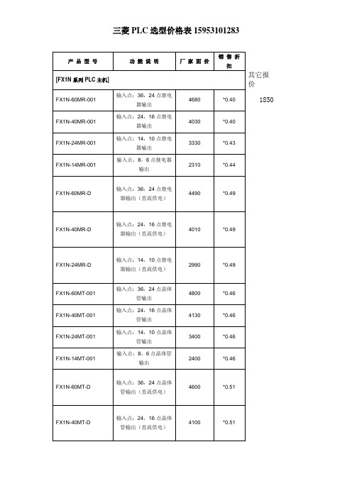
三菱变频器PLC选型价格表
0.6
FX-EEPROM-8
8K EEPROM MEMORY CASSETTE
620
0.6
FX-EEPROM-16
16K EEPROM MEMORY CASSETTE
1020
0.6
[通讯模块]
FX2NC-232-ADP
RS232通讯模块
1230
*0.60
FX2NC-485-ADP
RS485通讯模块
输入点:16,16继电器输出(直流供电)
5180
*0.49
FX2N-128MT-001
输入点:64,64点晶体管输出
10330
*0.44
FX2N-80MT-001
输入点:40,40点晶体管输出
7180
*0.42
FX2N-64MT-001
输入点:32,32点晶体管输出
6410
*0.42
FX2N-48MT-001
输入点:36,24点晶体管输出
4800
*0.46
FX1N-40MT-001
输入点:24,16点晶体管输出
4130
*0.46
FX1N-24MT-001
输入点:14,10点晶体管输出
3400
*0.46
FX1N-14MT-001
输入点:8,6点晶体管输出
2400
*0.46
FX1N-60MT-D
输入点:36,24点晶体管输出(直流供电)
4通道D/A
3270
*0.46
FX2N-5A
4通道A/D, 1通道D/A
3400
*0.53
FX2N-8AD
8通道A/D
7630
*0.46
LTC4263CS LTC4263CDE 示例电路981A B主板, 单端口自主PSE DAUGHT

LTC4263 in single port Power Over Ethernet (PoE) Power Sourcing Equipment (PSE) Midspan and End-point solutions. The LTC4263 is an autonomous sin-gle-channel PSE controller for use in IEEE802.3af compliant PoE systems. It includes an on-board pla-nar power MOSFET, internal inrush, current limit, and short circuit control, Powered Device (PD) detection and classification circuitry, and selectable AC or DC disconnect sensing. On-board control algorithms provide complete PSE Control operation without the need of a microcontroller. The LTC4263 simplifies ply and a small number of passive support compo-nents. Other options shown on the DC981A include Legacy PD detection enable, Midspan back off timer enable, power class enforce mode, power manage-ment enable. An LED for each port is driven by the respective LTC4263 to indicate the state of the port. Design files for this circuit board are available. Call the LTC factory.LTC is a trademark of Linear Technology CorporationTable 1. Typical DC981 Performance Summary (T A = 25°C)PARAMETER CONDITION VALUE Supply Voltage Voltage for IEEE802.3af Compliance at Port Output 46V to 57V Midspan Mode Detection Backoff Midspan Enabled, Failed Detection 3.2 seconds Detection Range Valid IEEE802.3af PD Detection 17k to 29.7k Set Maximum Allocated Power Power Management Enabled 17WEthernet Powered Pairs Pinout Endpoint PSE, Alternative A (MDI)Midspan PSE, Alternative B1/2(+), 3/6(-)4/5(+) , 7/8 (-)QUICK START PROCEDUREDemonstration circuit 981 is easy to set up to evaluate the performance of the LTC4263. Refer to Figure 2 for proper measurement equipment setup and follow the procedure below.1.Place jumpers in the following positions:ENENDISACACEN 2.Insert daughter card (DC981B) to main board (DC981A) at polarized connector J3.3.Apply 48V across VDD48 and VSS.4.Connect a scope probe at VOUT_MD and VOUT_EP both referenced to positive rail VDD48.5.Connect a valid PD to either Midspan PSE or Endpoint PSE.6.Connect a second PD to the open port.JP1 JP2 JP3 JP4 JP5 JP6Figure 1.Basic DC981A/B Equipment Setupto power the board. This in turn provides power to the Midspan PSE and Endpoint PSE outputs. On each solution, an LTC4263 provides detection of a PD, classification, power management, safe power on of the PD, port current limit, and disconnect detection. Midspan PSE and Midspan ModeIn the Midspan solution, a device (router, switch, etc.) that does not have PoE is connected to MIDSPAN IN. Data is passed through to MIDSPAN OUT along with PoE which goes out to a PD. Power is applied di-rectly to Ethernet pairs 4/5 and 7/8. The LTC4263 circuitry sits in a small layout area behind the RJ45 connector and switches power on the negative rail. To show the different functions of the LTC4263, jumpers allow for the user to select the options of AC or DC disconnect, legacy detection, Midspan backoff timing, and class enforcement. An LED that shows the status of the port is driven by a switcher in the LTC4263 to improve efficiency when VDD5 is pro-vided internally. Push button switch SW1 ties the shutdown pin to ground to disable the LTC4263 in the Midspan solution.A PSE implementing AlternativeB pin out must back off from detection for at least 2 seconds after a failed attempt. This is to avoid conflict of Detection, for ex-ample, should a potential Endpoint PSE and Midspan PSE be connected to the same PD. To enable this feature, set JP2 to DIS. JP2 ties the MIDSPAN pin to VDD5 to enable the LTC4263 backoff timer or to VSS to disable. A 3.2 second delay occurs after every failed detect cycle unless the result is open circuit. If held at VSS, no delay occurs after failed detect cycles. Endpoint PSEThe Endpoint solution is primarily shown on a small daughter card (DC981B). This card is the same height and width as the integrated RJ45 connector that it slides behind on the main board (DC981A). The RJ45 includes Ethernet magnetics and common ter card are VSS, VDD48 and VOUT. Power is switched over from the daughter card out to the Ethernet data pairs (1/2 and 7/8). A PHY can be con-nected to the “TO PHY” to pass data through to the data pairs along with PoE. LED drive and power management pins are also brought out for additional board functions. The board is set up for AC discon-nect, but can be reworked for DC disconnect by re-moving components and replacing with shorts in cer-tain locations. Two solder jumpers also provide se-lectable options for legacy detection and class en-force.Power ManagementThe Midspan and Endpoint PSE, although separate solutions on the DC981, are tied together at the PWRMGT pin for demonstration of the LTC4263 power management capability. Programmable on-board power management circuitry allows multiple LTC4263s to allocate and share power in multi-port systems, allowing maximum utilization of the 48V power supply – all without the intervention of a host processor.The LTC4263 sources current at the PWRMGT pin proportional to the class of the PD that it is powering. The voltage of this pin is checked before powering the port. The port will not turn on if this pin is more than 1V above VSS. The PWRMGT pins of the LTC4263s are tied together and connect to a resistor (RPM) and capacitor (CPM) in parallel to VSS to implement power management among multiple ports. This re-sistor is selected with the following equation:RPM= 213k * W / PFULL_LOADOn the DC981A, the default RPMis 12.4k for a full load power of 17W.19 33 73*RPM= 12.4kTable 3. Powered Device CombinationsPD COMBINATION 1ST PD 2ND PDClass 1 / Class 1 Powered PoweredClass 1 / Class 2 Powered PoweredClass 1 / Class 3** Powered Power Denied Class 2 / Class 2 Powered PoweredClass 2 / Class 3** Powered Power Denied Class 3 **/ Class 3** Powered Power Denied**Class 3 substitutable with Class 0 or 4.If power management is not used, move JP6 to DIS to tie the PWRMGT pins to VSS and disable this fea-ture.Class Enforce ModeENFORCE CLASS jumper JP1 ties the ENFCLS pin of the LTC4263 to either VDD5 or VSS to respectively enable or disable class enforce current limits. If held at VDD5, the LTC4263 will reduce the ICUT threshold for Class 1 or Class 2 PDs. If ENFCLS is held at VSS, ICUT remains at 375mA (typical) for all classes. Table 4. Port Current Limit According to ClassPD CLASS CURRENT THRESHOLD (TYPICAL)Class 1 100mAClass 2 175mAClass 0, 3, 4, or Class En-force Disabled375mALED DriveAn LED pin indicates the state of the port controlled by the LTC4263. When the port is powered, the LED is on; when disconnected or detecting, the LED is off. If an invalid signature is detected or a fault occurs, the LED will flash a pattern that the user or host sys-The logic 5V power supply can be supplied from the internal LTC4263 5V supply or an external 5V supply when above the internal supply. If the internal regula-tor is used, this pin should only be connected to the bypass capacitor and to any logic pins of the LTC4263 that are being held at VDD5.AC and DC DisconnectAC and DC disconnect are two different methods of detecting whether a valid PD is present and requires power. AC disconnect is the default method for the DC981 but can be converted to DC disconnect in the Midspan solution through two jumpers. Moving DISCON (JP4) to DC will short the ACCOUT pin to VSS and configure the LTC4263 to DC disconnect. Moving jumper setting for ACCOMP (JP5) to DC by-passes the AC blocking diode and removes the RC used for AC disconnect from the main circuit. Legacy DetectionLEGACY jumper JP3 controls whether legacy detect is enabled. If the LEGACY pin is held at VDD5 (EN se-lected), legacy detect is enabled and testing for a large capacitor is performed to detect the presence of a legacy PD on the port. If held at VSS (DIS se-lected), only IEEE 802.3af compliant PDs are de-tected. If left floating (no jumper), the LTC4263 enters force-power-on mode and any PD that generates be-tween 1V and 10V when biased with 270µA of detec-tion current will be powered as a legacy device. This mode is useful if the system uses a differential detec-tion scheme to detect legacy devices. Warning: Leg-acy modes are not IEEE 802.3af compliant.Figure 2.DC981 Options。
斩波稳定高精度低温漂锁存型霍尔效应开关 IC CC6103 4说明书
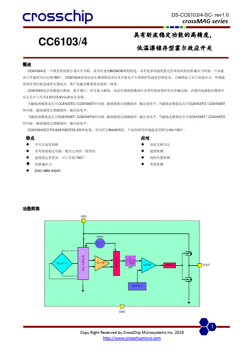
CC6103/4具有斩波稳定功能的高精度, 低温漂锁存型霍尔效应开关概述CC6103/4是一个锁存型的霍尔效应开关IC ,采用先进的BiCMOS 制程制造,具有优异的温度稳定性和很高的抗机械应力性能,产品最高工作温度可以达到150℃。
CC6103/4采用动态失调消除技术以及芯进电子专利保护的温度补偿技术,大幅降低了由于封装应力,环境温度变化等因素造成的失调电压,使产品磁灵敏度持高度的一致性。
CC6103/4包含电源稳压模块,霍尔薄片,信号放大模块,动态失调消除模块以及带有限流保护的功率输出级。
内置的电源稳压模块可以让芯片工作在2.5V 至5.5V 电源电压范围。
当磁场南极靠近芯片CC6103TO / CC6104ST 丝印面,磁场强度达到阈值时,输出低电平。
当磁场北极靠近芯片CC6103TO / CC6104ST 丝印面,磁场强度达到阈值时,输出高电平;当磁场南极靠近芯片CC6103ST / CC6104TO 丝印面,磁场强度达到阈值时,输出高电平。
当磁场北极靠近芯片CC6103ST / CC6104TO 丝印面,磁场强度达到阈值时,输出低电平。
CC6103/4提供TO-92S 和SOT23-3两种封装,均为符合RoHS 规范,产品的使用环境温度范围为-40~150℃。
功能框图动态失调消除放大器预驱动采样保持比较器50KHzLPF基准电压霍尔单元GND特点◆ 开关点高度对称◆ 具有斩波稳定功能,批次之间的一致性好 ◆ 温度稳定性优异,可工作到150℃ ◆ 抗机械应力◆ ESD HBM 4000V 应用◆ 直流无刷马达 ◆ 速度检测 ◆ 线性位置检测 ◆角度检测名称 封装型号 备注 CC6103TO TO-92S 袋装,1000片/包 CC6103ST SOT23-3 卷盘,3000片/卷 CC6104TO TO-92S 袋装,1000片/包 CC6104STSOT23-3卷盘,3000片/卷开关输出 vs. 磁场极性VoutS poleV OHV OLB HB RPB OPN pole CC6103TO / 6104STVoutN poleV V OL 0B HB RP B OPS poleCC6103ST / 6104TO注意: 磁场加在芯片的丝印面管脚描述CC6103XXYYWW132V DD V OUTGND1236103V DDGND V OUTCC6104XXYYWW132V DD V OUTGND1236104V DDGNDV OUT名称 管脚编号 功能 TO-92SSOT23-3V DD 1 1 电源电压 GND 2 3 地 V OUT32输出参数符号数值单位电源电压V DD-0.3~5.5 V输出脚耐压V OUT-0.3~VDD+0.3 V磁场强度 B 无限制Gauss工作环境温度T A-40~150 ℃存储环境温度Ts -50至160 ℃ESD(HBM) 4000 V电气参数参数符号测试环境最小值典型值最大值单位电源电压V DD- 2.5 - 5.5 V静态电流I DD25℃,V DD=5.0V - 2 3 mA输出电流I OUT25℃,V DD=5.0V,纯阻性负载- - 50 mA 输出饱和压降V SAT25℃,I OUT=50mA - - 0.4 V上升时间tr R L=820Ω,C L=10pF - 1.0 - us下降时间tf R L=820Ω,C L=10pF - 2.5 - us磁参数参数符号测试环境最小值典型值最大值单位工作点B OP25℃15 30 45 Gauss释放点B RP25℃-45 -30 -15 Gauss迟滞B HYS25℃50 60 70 Gauss 典型应用电路静态电流vs. 工作电压磁感应点vs. 工作电压磁感应点vs. 温度封装信息(1)TO-92S package0.730.414.093.0214.991.270.431.02MAXHall 感应点位置1.442.01CC6103打标信息: 第一行: CC6103-产品名称 第二行: XXYYWW XX – 代码YY – 封装年份的后两位数 WW – 封装时的星期数CC6104打标信息: 第一行: CC6104-产品名称第二行: XXYYWW XX – 代码YY – 封装年份的后两位数 WW – 封装时的星期数注意: 所有单位均为毫米。
LTC4054

器从改脚引出,控制输出电压。关断模式下,此电阻分压器从改脚断开连接。 VCC(4):电源输入正极。向充电器供电,电压范围 4.5V 至 6.5V。接 1μF 对地电容以减少纹波。 PROG(5):充电电流编程器脚,充电电流监测与充电开关。可通过此脚与地之间链接的 1%电阻来设定
工作范围(2)
2of 6
参数 输入电压
结温
LTC4054
独立线性锂电池充电器
符号
V CC
TJ
数值 -0.3 ~ +10 -40 ~ +80
单位 V °C
直流电学特性
(VCC = 5V, TJ= 25 °C,特别标注除外)
参数
符号 整流输出电压 BAT脚电流 涓流充电电流 涓流隔值电压
4of 6
应用说明
LTC4054
独立线性锂电池充电器
稳定性:
恒流反馈控制环路无需输出电容即可输出稳定的电压给外接在充电器输出端上的电池。如无外接电 池,输出应接一输出电容以 减少纹波。如使用大容量、低ESR的陶瓷电容,则应在电容上串一个1Ω为 佳;如使用钽电容则无需串联电阻。
恒流模式下,PROG脚为反馈环路。恒流模式的稳定性受PROG脚的阻抗影响。如无外加电容于 PROG脚上,则当编程电阻高至20KΩ时,充电器仍能保持稳定;然而,如有外加电容,最大允许编程 电阻将减小。
1of 6
管脚描述
LTC4054
独立线性锂电池充电器
管脚号
1 2 3 4 5
管脚名
CHRG GND BAT VCC PROG
功能
- 1、下载文档前请自行甄别文档内容的完整性,平台不提供额外的编辑、内容补充、找答案等附加服务。
- 2、"仅部分预览"的文档,不可在线预览部分如存在完整性等问题,可反馈申请退款(可完整预览的文档不适用该条件!)。
- 3、如文档侵犯您的权益,请联系客服反馈,我们会尽快为您处理(人工客服工作时间:9:00-18:30)。
1210644fbPARAMETERCONDITIONSMINTYP MAX UNITS Passband Gain Referenced to 0dB, 1Hz to 0.05f CUTOFF ●–0.50.1dB Gain TempCo0.0002dB/°C Passband Edge Frequency, f C 20 ± 1%kHz Gain at f CReferenced to Passband Gain, f C = 20kHz ●–0.40.7dB –3dB Frequency 50:1 (Cauer Response)21.5kHz 100:1 (Transitional Response)10kHz Passband Ripple (Note 2)0.1f C to 0.95f C Referenced to Passband Gain ●–0.150.6dB Stopband Attenuation At 1.7f CUTOFF ●–56–60dB Stopband Attenuation At 2f CUTOFF –80dB Input Frequency Range 50:1, Pin 10 at V +0f CLK kHz 100:1, Pin 10 at V –0f CLK /2kHz Output Voltage Swing and V S = ±2.37V ●±1.1V Operating Input Voltage Range V S = ±5V ●±3.1V V S = ±7.5V●±5.0VTotal Harmonic Distortion V S = ±5V, Input = 1V RMS at 1kHz 0.015%V S = ±7.5V, Input = 3V RMS at 1kHz 0.03%Wideband NoiseV S = ±5V, Input = GND 1Hz to 999kHz 120µV RMS V S = ±7.5V, Input = GND 1Hz to 999kHz135µV RMS(Note 1)Total Supply Voltage (V + to V –)............................16.5V Input Voltage at Any Pin......V – –0.3V ≤ V IN ≤ V + +0.3V Power Dissipation..............................................400mW Storage Temperature Range.................–65°C to 150°CLead Temperature (Soldering, 10 sec)..................300°C Operating Temperature RangeLTC1064-4M (OBSOLETE)...............–55°C to 125°C LTC1064-4C .......................................–40°C to 85°CThe ● denotes the specifications which apply over the full operatingtemperature range, otherwise specifications are at T A = 25°C. V S = ±7.5V, 50:1, f CLK = 1MHz, f C = 20kHz, R1 = 10k, TTL clock input level unless otherwise specified.ELECTRICAL CHARACTERISTICSABSOLUTE AXI U RATI GSW W WU3410644fbPower Supply Current vs Power Supply VoltageTable 1. Wideband Noise (µV RMS ). Input Grounded, f CLK = 1MHzGain vs Frequency with CompensationDevice to Device Phase MatchingTotal Harmonic DistortionFREQUENCY (Hz)10kG A I N (d B )50–5–10–15–20–25–30–35100k1M1064-4 G04INPUT LEVEL (V RMS )0.01D I S T O R T I O N (%)0.11.01064-4 G06FREQUENCY (kHz)6P H A S E M A T C H(±D E G )5.55.04.54.03.53.02.52.01.51.00.50101214161820221064-4 G05248Transient Responsef CLK = 1MHz, Ratio = 50:1,f C = 20kHz, V S = ±7.5V, 1kHz Square Wave InputTOTAL POWER SUPPLY VOLTAGE (V)02610141822P O W E R S U P P L Y C U RR E N T (m A )484440363228242016128404812161064-4 G0720242V /D I V0.1ms/DIVV S = ±2.37VV S = ±5V V S = ±7.5V Noise Noise Noise Pin 10 tof CLK /f CUTOFFµV RMS µV RMS µV RMS V +50:1120135145V –100:1100120130TYPICAL PERFOR A CE CHARACTERISTICSU W510644fbTable 2. Gain/Phase, Pin 10 at V +, Typical Responsef CUTOFF = 1kHz, V S = ±5V, T A = 25°C, f CLK = 50kHz, Ratio = 50:1Table 3. Gain/Delay, Pin 10 at V +, Typical Responsef CUTOFF = 1kHz, V S = ±5V, T A = 25°C, f CLK = 50kHz, Ratio = 50:1FREQUENCY(kHz)GAIN (dB)PHASE (deg)0.200–0.075–59.9900.400–0.050–122.4000.6000.020169.3000.8000.06088.5001.0000.090–26.1001.200–15.640–175.1001.400–34.700126.5001.600–51.70087.6001.800–68.60038.4002.000–84.110–47.860FREQUENCY(kHz)GAIN (dB)DELAY (ms)0.200–0.0740.8440.300–0.0700.8670.400–0.0500.8990.500–0.0200.9490.6000.020 1.0210.7000.050 1.1220.8000.060 1.2750.9000.120 1.5921.0000.090 2.1601.100–5.020 2.0701.200–15.6501.288Table 4. Gain/Phase, Pin 10 at V –, Typical Responsef –3dB = 1kHz, V S = ±5V, T A = 25°C, f CLK = 100kHz, Ratio = 100:1FREQUENCY(kHz)GAIN (dB)PHASE (deg)0.200–0.179–60.0900.400–0.440–122.0000.600–0.810170.8000.800–1.48091.9001.000–3.500–16.3001.200–17.720–140.5001.400–35.700164.8001.600–52.700135.0001.800–71.900114.0002.000–96.160–49.670Table 5. Gain/Delay, Pin 10 at V –, Typical Responsef –3dB = 1kHz, V S = ±5V, T A = 25°C, f CLK = 100kHz, Ratio = 100:1Table 6. Gain/Phase, Pin 10 at GND V S = ±5V, T A = 25°CFREQUENCY(kHz)GAIN (dB)PHASE (deg)0.200–0.383–47.1400.400–1.000–92.0000.600–1.300–134.3000.800–0.280–178.8001.000 2.670109.2001.200–3.500 6.0001.400k –12.510–47.4001.600–20.000–88.8001.800–27.300–127.8002.000–35.000–164.200FREQUENCY(kHz)GAIN (dB)DELAY (ms)0.200–0.1740.8420.300–0.3000.8610.400–0.4400.8880.500–0.6100.9330.600–0.8100.9990.700–1.090 1.0950.800–1.480 1.2420.900–2.080 1.5031.000–3.500 1.8321.100–8.720 1.7241.200–17.7201.183TYPICAL PERFOR A CE CHARACTERISTICSU W610644fbTYPICAL PERFOR A CE CHARACTERISTICSU WFREQUENCY (kHz)GAIN (dB)PHASE (deg)10.000–0.094–75.90012.000–0.100–91.40014.000–0.090–107.20016.000–0.080–123.30018.000–0.060–139.60020.000–0.040–156.50022.000–0.020–173.80024.0000.000168.20026.0000.020149.40028.0000.030130.00030.0000.020109.40032.0000.01087.70034.000–0.02064.60036.000–0.03039.50038.000–0.01011.40040.000–0.070–22.00042.000–0.920–64.10044.000–4.000–110.10046.000–8.970–147.00048.000–14.320–173.50050.000–19.460166.800FREQUENCY (kHz)GAIN (dB)PHASE (deg)10.000–0.096–32.39020.000–0.100–64.90030.000–0.080–98.10040.000–0.040–132.30050.0000.020–168.20060.0000.070153.60070.0000.040112.10080.000–0.12066.40090.000–0.46014.600100.000–1.310–49.300110.000–5.640–129.000120.000–14.530167.800130.000–23.800126.700140.000–32.60096.200150.000–41.00071.300160.000–49.20049.200170.000–57.50029.000180.000–66.5009.800190.000–77.770–2.320200.000–92.05076.740FREQUENCY (kHz)GAIN (dB)PHASE (deg)110.000–7.420172.100120.000–18.240119.400130.000–28.00083.300140.000–37.00054.000150.000–45.700–27.600160.000–54.300 2.100170.000–63.300–24.900180.000–73.610–60.210190.000–85.300–138.990200.000–83.390129.580Table 7. Gain/Phase for Figure 6.Typical Response, Pin 10 at V +, f CUTOFF = 40kHz,V S = ±7.5V, f CLK = 2MHz, Ratio = 50:1Table 8. Gain/Phase for Figure 7.Typical Response, Pin 10 at V +, f CUTOFF = 100kHz,V S = ±7.5V, T A = 25°C, f CLK = 5MHz, Ratio = 50:1Table 9. Gain/Phase for Figure 7.Typical Response, Pin 10 at V + f CUTOFF = 100kHz,V S = ±7.5V, T A = 125°C, f CLK = 5MHz, Ratio = 50:1FREQUENCY (kHz)GAIN (dB)PHASE (deg)10.000–0.071–33.80020.000–0.040–67.80030.0000.050–102.50040.0000.190–138.30050.0000.410–176.10060.0000.670143.10070.0000.92098.40080.000 1.15048.20090.000 1.530–10.900100.0001.110–96.500UUUPI FU CTIO SINV C, COMP1, INV A, COMP2 (Pins 1, 6, 7 and 13): To obtain a Cauer response with minimum passband ripple and cutoff frequencies above 20kHz, compensating com-ponents are required. Figure 6 uses ±7.5V power supplies and compensation components to achieve up to 40kHz sweepable cutoff frequencies and ±0.1dB passband ripple. Table 7 lists the typical amplitude response of Figure 6. Figure 7 illustrates the compensation scheme required to obtain a 100kHz cutoff frequency; Graph 4 and Tables 8 and 9 list the typical response of Figure 7 for 25°C and 125°C ambient temperature. As shown the ripple in-creases at high temperatures but still a ±0.25dB figure can be obtained for ambient temperatures below 70°C. V IN, V OUT (Pins 2, 9): The input Pin 2 is connected to a 12k resistor tied to the inverting input of an op amp. Pin2 is protected against static discharge. The device’s output, Pin 9, is the output of an op amp which can typically source/sink 3mA/1mA. Although the internal op amps are unity gain stable, driving long coax cables is not recom-mended.When testing the device for noise and distortion, the output, Pin 9, should be buffered (Figure 4). The op amp power supply wire (or trace) should be connected directly to the power source.To eliminate any output clock feedthrough, Pin 9 should be buffered with a simple R, C lowpass filter (Figure 5). The cutoff frequency of the output filter should be f CLK/3.AGND (Pins 3, 5): For dual supply operation these pins should be connected to a ground plane. For single supply operation both pins should be tied to one half supply (Figure 2).V+, V– (Pins 4, 12): Should be bypassed with a 0.1µF capacitor to an adequate analog ground. Low noise, nonswitching power supplies are recommended. To avoid latchup when the power supplies exhibit high turn-on transients, a 1N5817 Schottky diode should be added from the V+ and V– pins to ground (Figures 1 and 2). INV A, R(h, I) (Pins 7, 14):A very short connection between Pin 7 and Pin 14 is recommended. This connec-tion should be preferably done under the IC package. In a breadboard, use a one inch, or less, shielded coaxial cable; the shield should be grounded. In a PC board, use a one inch trace or less; surround the trace by a ground plane. NC (Pin 8 ): Pin 8 is not internally connected, it should be preferably grounded.50/100 Ratio (Pin 10):F or an f CLK/f C ratio of 50:1, Pin 10 should be tied to V+. For an f CLK/f–3dB ratio of 100:1, Pin 10 should be tied to V–. When Pin 10 is at midsupplies (i.e. ground), the filter response is neither Cauer nor transitional. Table 6 illustrates this response. Bypassing Pin 10 with a 0.1µF capacitor reduces the already small clock feedthrough.(Pin Numbers Refer to the 14-Pin Package)710644fb810644fbFigure 3. Level Shifting the Input T 2L Clock for Single Supply Operation ≥6V.Figure 4. Buffering the Filter Output. The Buffer Op Amp Should Not Share the LTC1064-4 Power Lines.Figure 5. Adding an Output Buffer-Filter to Eliminate Any Clock Feedthrough.Passband Error of Output Buffer is ±0.1dB to 50kHz, –3dB at 94kHz.V 1064-4 F030.1µ2LV INV 0.1µOUTµFV Figure 1. Using Schottky Diodes to Protectthe IC from Power Supply SpikesFigure 2. Single Supply Operation. If Fast Power Up or DownTransients are Expected, Use a 1N5817 Schottky Diode Between Pin 4 and Pin 5.V V –µFV +TYPICAL APPLICATIO SU91010644fbN Package14-Lead PDIP (Narrow 0.300)(LTC DWG # 05-08-1510)UPACKAGE DESCRIPTIO*THESE DIMENSIONS DO NOT INCLUDE MOLD FLASH OR PROTRUSIONS. MOLD FLASH OR PROTRUSIONS SHALL NOT EXCEED .010 INCH (0.254mm)11Information furnished by Linear Technology Corporation is believed to be accurate and reliable.However, no responsibility is assumed for its use. Linear Technology Corporation makes no represen-tation that the interconnection of its circuits as described herein will not infringe on existing patent rights.LTC1064-41210644fbLinear Technology Corporation1630 McCarthy Blvd., Milpitas, CA 95035-7417(408) 432-1900 ● FAX: (408) 434-0507 ● LINEAR TECHNOLOGY CORPORA TION 1991LW/TP 1202 1K REV B • PRINTED IN USAFigure 6. Compensating LTC1064-4 for PassbandRipple of ±0.1dB and f CUTOFF Sweeps to 40kHz.–7.5VµF–7.5VµFFigure 7. Compensating LTC1064-4 for f CUTOFF = 100kHz,Gain at f CUTOFF = –1.3dB, Table 8.TYPICAL APPLICATIO SUPART NUMBER DESCRIPTIONCOMMENTSLTC1069-18th Order Elliptic LowpassS0-8 Package, Low Power LTC1069-6Single Supply, 8th Order Elliptic Lowpass S0-8 Package, Very Low PowerLTC1569-6DC Accurate, 10th Order Lowpass Internal Precision Clock, Low Power, S0-8 Package LTC1569-7DC Accurate, 10th Order LowpassInternal Precision Clock, Delay Equalized, S0-8 PackageRELATED PARTS。