MXP-488MD中文资料
J.Nanopart.Res.,2009,11,1513–Rheological behaviour of ethylene glycol-titanate nanotube nano

BRIEF COMMUNICATIONRheological behaviour of ethylene glycol-titanate nanotube nanofluidsHaisheng Chen ÆYulong Ding ÆAlexei Lapkin ÆXiaolei FanReceived:11July 2008/Accepted:4February 2009/Published online:26February 2009ÓSpringer Science+Business Media B.V.2009Abstract Experimental work has been performed on the rheological behaviour of ethylene glycol based nanofluids containing titanate nanotubes over 20–60°C and a particle mass concentration of 0–8%.It is found that the nanofluids show shear-thinning behaviour particularly at particle concentrations in excess of *2%.Temperature imposes a very strong effect on the rheological behaviour of the nanofluids with higher temperatures giving stronger shear thinning.For a given particle concentration,there exists a certain shear rate below which the viscosity increases with increasing temperature,whereas the reverse occurs above such a shear rate.The normalised high-shear viscosity with respect to the base liquid viscosity,however,is independent of temperature.Further analyses suggest that the temperature effects are due to the shear-dependence of the relative contributions to the viscosity of the Brownian diffusion and convection.The analyses also suggest that a combination of particle aggregation and particle shape effects is the mechanism for the observed high-shear rheological behaviour,which is also supported by the thermal conductivity measure-ments and analyses.Keywords Rheological behaviour ÁEthylene glycol ÁTitanate nanotube ÁNanofluid ÁThermal conductivityNanofluids are dilute suspensions of particles with at least one dimension smaller than about 100nm (Choi 1995).Such a type of materials can be regarded as functionalized colloids with special requirements of a low-particle loading,a high-thermal performance,favourable flow/rheolgocial behaviour,and a great physical and chemical stability over a wide range of process and solution chemistry conditions.Nano-fluids have been shown to be able to enhance heat transfer (Choi 1995;Wang and Mujumdar.2007),mass transfer (Krishnamurthy et al.2006),and wetting and spreading (Wasan and Nikolov 2003),and have been a hot topic of research over the past decade (Wang and Mujumdar 2007;Keblinski et al.2005).Most published studies have focused on the heat transfer behaviour including thermal conduction (Choi 1995;Wang et al.1999;Wang and Mujumdar 2007;Keblinski et al.2005;Eastman et al.2001;He et al.2007;Ding et al.2006),phase change (boiling)heat transfer (Das et al.2003;Pak and Cho 1998),and convective heat transfer (Wang and Mujumdar 2007;Keblinski et al.2005;He et al.2007;Ding et al.2006,Chen et al.2008;Prasher et al.2006a and Yang et al.2005).Only few studies have been devoted to the rheological behaviour ofH.Chen ÁY.Ding (&)Institute of Particle Science and Engineering,University of Leeds,Leeds,UK e-mail:y.ding@pkin ÁX.FanDepartment of Chemical Engineering,University of Bath,Bath,UKJ Nanopart Res (2009)11:1513–1520DOI 10.1007/s11051-009-9599-9nanofluids(He et al.2007;Chen et al.2008;Prasher et al.2006a,b;Kwak and Kim2005;Lee et al.2006), although there is a large body of literature on suspensions rheology;see for example,Russel et al. (1991);Chow(1993);Petrie(1999),Larson(1999); Goodwin et al.(2000)l;Mohraz et al.(2004);Larson (2005);Egres and Wagner(2005);Abdulagatov and Azizov(2006).Particularly,there is little in the literature on the effect of temperature on the rheo-logical behaviour of nanofluids.Clearly,there is a gap in the current rheological literature for this type offluids.Furthermore,recent work has shown that the thermal behaviour of nanofluids correlates well with their rheological behaviour(Prasher et al.2006a, b;Chen et al.2007a;Abdulagatov and Azizov2006). In a recent study,we investigated systemically the rheological behaviour of ethylene glycol(EG)based spherical TiO2nanofluids(Chen et al.2007b).The results show that the nanofluids are Newtonian over a shear rate range of0.5–104s-1and the shear viscosity is a strong function of temperature,particle concentration and aggregation microstructure.This work is concerned about the rheological behaviour of EG based nanofluids containing titanate nanotubes (TNT).The specific objectives of the work are to investigate the effects of particle shape,particle concentration and temperature on nanofluids viscosity, and to understand the relationship between the rheo-logical behaviour and the effective thermal conductivity of nanofluids.It is for thefirst time that the rheological behaviour of a highly viscous EG based TNT nanofluids is investigated in a systematic manner.As will be seen later,the results of this work provide further evidence that the rheological measure-ments could provide information of particle structuring for predicting the effective thermal conductivity of nanofluids.The EG-TNT nanofluids used in this work were formulated by using the so-called two-step method with EG purchased from Alfa Aesar and TNT synthesized in our labs using a method described elsewhere(Bavykin et al.2004).The details of nanofluids formulation can be found elsewhere(Wen and Ding2005;He et al.2007;Chen et al.2007b). The TNT particles have a diameter(b)of*10nm and a length(L)of*100nm,giving an aspect ratio of(r=L/b)of*10.To avoid complications in interpreting the experimental results,no dispersants/ surfactants were used in the formulation.The nanofluids formulated were found stable for over 2months.The rheological behaviour of the nano-fluids was measured by using a Bolin CVO rheometer (Malvern Instruments,UK)over a shear rate range of 0.03–3,000s-1,a nanoparticle mass concentration of w=0–8%,and a temperature range of20–60°C (293–333K).The nanofluids were characterised for their size by using a Malvern Nanosizer(Malvern Instruments,UK)and a scanning electron microscope (SEM).The average effective particle diameter was found to be*260nm for all nanofluids formulated. This size is much larger than the equivalent diameter of the primary nanoparticles due to aggregation;see later for more discussion.Note that the particle size characterisation was performed both before and after the rheological measurements and no detectable changes to particle size were found.Figure1shows the viscosity of pure EG and EG-TNT nanofluids as a function of shear rate at 40°C.The results at other temperatures are similar.It can be seen that the EG-TNT nanofluids exhibit highly shear-thinning behaviour particularly when the TNT concentration exceeds*2%.Such behaviour is different from the observed Newtonian behaviour of EG-TiO2nanofluids containing spherical nanoparti-cles over similar shear rate range(Chen et al.2007b) where the base liquid,EG,is the same as that used in the current wok.The behaviour is similar to the observations of carbon nanotube nanofluids(Ding et al.2006)and CuO nanorod nanofluids(Kwak and Kim2005),although there are important differencesbetween them such as temperature dependence as will be discussed later.The shear-thinning behaviour of well-dispersed suspensions can be interpreted by the structuring of interacting particles(Doi and Edwards1978a,b and Larson1999).In a quiescent state,a rod-like particle has three types of motion due to Brownian diffusion: rotational(end-over-end)motion around the mid-point and translational motion in parallel or perpendicular to the long axis.For dilute suspensions with a number density,c,ranging between0and1/L3or volume fraction,u,ranging between0and1/r2),the average spacing between the particles is larger than the longest dimension of the rod,and zero shear viscosity can be approximated by gð0Þ%g0ð1þAÁcL3Þwith g0the base liquid viscosity and A,a numerical constant(Doi and Edwards1978a).For suspensions with 1/L3\c\1/bL2or1/r2\f/\1/r,the rod-like particles start to interact.The rotational motion is severely restricted,as well as the translational motion perpendicular to the long axis,and the zero shear viscosity can be estimated by gð0Þ%g0ð1þðBcL3Þ3Þ; with B a numerical constant(Doi and Edwards1978b). As a consequence,the zero shear viscosity can be much greater than the base liquid viscosity.The large viscosity is due to the rod-like shape effect and the viscosity is very sensitive to shear,which tends to align particles and hence the shear-thinning behaviour as shown in Fig.1.Note that the above mechanism can give a qualitative explanation for the experimental observations at low-shear rates and the shear-thinning behaviour as shown in Fig.1,it does not explain the high-shear viscosity of the nanofluids,which will be discussed later.It should also be noted that the criteria for classifying nanofluids given above need to be modified due to the presence of aggregates;see later for more discussion.Figure2shows the shear viscosity of4.0%EG-TNT nanofluids as a function of shear rate at different temperatures.The results under other concentrations are similar.It can be seen that the temperature has a very strong effect on the rheological behaviour of nanofluids with higher temperatures giving stronger shear thinning.For shear rates below*10s-1,the shear viscosity increases with increasing temperature, whereas the trend is reversed when the shear rate is above*10s-1.As mentioned above,this behaviour was not observed for carbon nanotube(Ding et al. 2006)and CuO nanorod(Kwak and Kim2005)nanofluids and we have not seen reports on such behaviour for nanofluids in the literature;see later for more discussion on the underlying mechanisms. Figure2also shows that the strongest shear thinning occurs at40–60°C,whereas very weak-shear thinning takes places at20–30°C.It is also noted that the shear viscosity of nanofluids at all temperatures investigated approaches a constant at high-shear rates.If the high-shear viscosity is plotted against temperature,Fig.3is obtained where the shear rate corresponding to the high-shear viscosity is taken as *2,000s-1.An inspection of all the data indicates that theyfit the following equation very well:ln g¼AþBÂ1000=TþCðÞð1Þwhere g is the shear viscosity(mPaÁs),T is the absolute temperature(K),and A,B and C areconstants given in Table1.Equation(1)takes a similar format as that widely used for liquid viscosity (Bird et al.2002)and for EG based nanofluids containing spherical particles(Chen et al.2007b).If the measured high-shear viscosity is normalized with respect to the shear viscosity of the base liquid, the relative increaseðg i¼ðgÀg0Þ=g0Þof the high-shear viscosity is found to be only a function of concentration but independent of temperature over the temperature range investigated in this work.The relative increments in the shear viscosities of nano-fluids containing0.5%,1.0%,2.0%,4.0%and8.0% particles are 3.30%,7.00%,16.22%,26.34%and 70.96%,respectively.Similar temperature indepen-dence of the shear viscosity was also observed for EG-TiO2and water-TiO2nanofluids containing spherical nanoparticles(Chen et al.2007b).The experimentally observed temperature depen-dence can be interpreted as follows.Given the base liquid and nanoparticles,the functional dependence of viscosity on shear rate is determined by the relative importance of the Brownian diffusion and convection effects.At temperatures below*30°C,the contribu-tion from the Brownian diffusion is weak due to high-base liquid viscosity.As a consequence,the shear dependence of the suspension is weak(Fig.2).The contribution from the Brownian diffusion becomes increasingly important with increasing temperature particularly above40°C due to the exponential dependence of the base liquid viscosity on temperature (Fig.3).At very high-shear rates,the Brownian diffusion plays a negligible role in comparison with the convective contribution and hence independent of the high-shear viscosity on the temperature.We now start to examine if the classical theories for the high-shear viscosity predict the experimental measurements(note that there is a lack of adequate theories for predicting the low shear viscosity).Figure4shows the shear viscosity increment as a function of nanoparticle volume concentration together with the predictions by the following Brenner &Condiff Equation for dilute suspensions containing large aspect ratio rod-like particles(Brenner and Condiff1974):g¼g01þg½ uþO u2ÀÁÀÁð2Þwhere the intrinsic viscosity,½g ;for high-shear rates has the following form(Goodwin and Hughes2000):½g ¼0:312rln2rÀ1:5þ2À0:5ln2rÀ1:5À1:872rð3ÞAlso included in Fig.4are the data for EG-TiO2 nanofluids with spherical nanoparticles(Chen et al. 2007b)and predictions by the Einstein Equation (Einstein1906,1911)for dilute non-interacting suspensions of spherical particles,g¼g01þ2:5uðÞ: It can be seen that both the Einstein and Brenner& Condiff equations greatly underpredict the measured data for the EG-TNT nanofluids.The high-shear viscosity of EG-TNT nanofluids is much higher than that of the EG-TiO2nanofluids containing spherical nanoparticles,indicating a strong particle shape effect on the shear viscosity of nanofluids.Although the shear-thinning behaviour of the nanofluids could be partially attributed to the structuring of interacting rod-like particles,the large deviation between the measured high-shear viscosity and the predicted ones by the Brenner&Condiff equation cannot fully be interpreted.In the following,an attempt is made to explain the experimental observations from the viewpoint of aggregation of nanaoparticles,which have been shown to play a key role in thermal behaviour of nanofluids in recent studies(Wang et al. 2003;Xuan et al.2003;Nan et al.1997;Prasher et al. 2006a,b;Keblinski et al.2005).Such an approach is also supported by the SEM and dynamic lightTable1Empirical constants for Eq.(1)a Maximum discrepancies;b Minimum discrepancies Concentration(wt%)A B C MaxD a(%)MinD b(%)0.0-3.21140.86973-154.570.62-1.440.5-3.42790.94425-148.490.93-0.471.0-2.94780.81435-159.14 1.11-0.692.0-2.2930.65293-174.57 1.64-0.694.0-2.63750.7574-165.820.99-0.948.0-2.73140.93156-145.010.88-1.57scattering analyses,which,as mentioned before, show clear evidence of particle aggregation.According to the modified Krieger-Dougherty equation(Goodwin and Hughes2000;Wang et al. 2003;Xuan et al.2003;Nan et al.1997),the relative viscosity of nanofluids,g r,is given as:g r¼1Àu a=u mðÞÀ½g u mð4Þwhere u m is the maximum concentration at which the flow can occur and u a is the effective volume fraction of aggregates given by u a¼u=u ma with u ma the maximum packing fraction of aggregates.As aggre-gates do not have constant packing throughout the structure,the packing density is assumed to change with radial position according to the power law with a constant index(D).As a result,u a is given as u a¼uða a=aÞ3ÀD;with a a and a,the effective radii of aggregates and primary nanoparticles,respectively. The term D is also referred as the fractal index meaning the extent of changes in the packing fraction from the centre to the edge of the aggregates.Typical values of D are given in normal textbook as D= 1.8–2.5for diffusion limited aggregation(DLA)and D=2.0–2.2for reaction limited aggregation(RLA); see for example Goodwin and Hughes(2000).For nanofluids containing spherical nanoparticles,the value of D has been shown experimentally and numerically to be between1.6and1.8(Wang et al. 2003,Xuan et al.2003)and between1.8and2.3, respectively(Waite et al.2001).A typical value of 1.8is suggested for nanofluids made of spherical nanoparticles(Prasher et al.2006a,b).However,little research has been found on the fractal index for nanofluids containing rod-like nanoparticles.The colloid science literature suggests a fractal index of 1.5–2.45for colloidal suspensions depending on the type of aggregation,chemistry environment,particle size and shape and shearflow conditions(Haas et al. 1993;Mohraz et al.2004;Hobbie and Fry2006; Micali et al.2006;Lin et al.2007).In a recent study, Mohraz et al.(2004)investigated the effect of monomer geometry on the fractal structure of colloi-dal rod aggregates.They found that the fractal index is a non-linear function of the monomer aspect ratio with the D increasing from*1.80to*2.3when the aspect ratio of the rod-like nanoparticles increases from1.0to30.6.Based on the above,a value of D=2.1is taken for nanofluids used in this work (Mohraz et al.2004,Lin et al.2007).Although the fractal model may appear to simplify the complexity of microstructures in aggregating systems containing rod-like particles,excellent agreement between the model prediction and experimental measurements exists when a a/a=9.46;see Fig.4.Here the aggregates are assumed to formflow units of an ellipsoidal shape with an effective aspect ratio of r a¼L a=b a;where L a and b a are the effective length and diameter,respectively.In the calculation,a typical value of u m of0.3is taken(Barnes et al.1989),and the intrinsic viscosity[g]is calculated by Eq.(3).It is to be noted that the aggregate size thatfits well to the rheological data(Fig.4)is consistent with the particle size analyses using both the SEM and the Malvern Nanosizer.A comparison between the EG-TNT data (a a/a=9.46,D=2.1,u m=0.30)and the EG-TiO2 data(a a/a=3.34,D=1.8,u m=0.605)(Chen et al. 2007b)in Fig.4suggests that the larger aggregate size in TNT nanofluids be an important factor responsible for the stronger shear-thinning behaviour and higher shear viscosity of TNT nanofluids.An inspection of Eq.(4)indicates that the effec-tive volume fraction u a u a¼u a a=aðÞ3ÀDis much higher than the actual volume fraction(u).This leads to the experimentally observed high-shear viscosity even for very dilute nanofluids,according to the classification discussed before.As a consequence,the demarcations defining the dilute and semi-concen-trated dispersions should be changed by using the effective volume fraction.The model discussed above can also provide a macroscopic explanation for the temperature indepen-dence of the high-shear viscosity.From Eq.(4),one can see that the relative high-shear viscosity depends on three parameters,the maximum volume fraction, u m,the effective volume fraction,u a and the intrinsic viscosity,[g].For a given nanofluid at a temperature not far from the ambient temperature,the three parameters are independent of temperature and hence the little temperature dependence of the relative shear viscosity.Microscopically,as explained before,the temperature-independent behaviour is due to negligi-ble Brownian diffusion compared with convection in high-shearflows.To further illustrate if the proposed aggregation mechanism is adequate,it is used to predict the effective thermal conductivity of the nanofluids by using the following conventional Hamilton–Crosser model(H–C model)(Hamilton and Crosser1962):k=k0¼k pþðnÀ1Þk0ÀðnÀ1Þuðk0Àk pÞk pþðnÀ1Þk0þuðk0Àk pÞð5Þwhere k and k0are,respectively,the thermal conductivities of nanofluids and base liquid,n is the shape factor given by n=3/w with w the surface area based sphericity.For TNT used in this work,the sphericity w is estimated as0.6(Hamilton and Crosser1962).For suspensions of aggregates,the above equation takes the following form:k=k0¼k aþðnÀ1Þk0ÀðnÀ1Þu aðk0Àk aÞa0a0að6Þwhere k a is the thermal conductivity of aggregates.To calculate k a,Eq.(6)is combined with the following Nan’s model(Nan et al.2003)for randomly dispersed nanotube-based composites:k a=k0¼3þu in½2b xð1ÀL xÞþb zð1ÀL zÞ3Àu in½2b x L xþb z L zð7Þwhere/in is the solid volume fraction of aggregates, b x¼ðk xÀk0Þ=½k mþL xðk tÀk mÞ and b z¼ðk zÀk0Þ=½k mþL zðk tÀk mÞ with k x,k m and k t being the thermal conductivities of nanotubes along trans-verse and longitudinal directions and isotropic thermal conductivity of the nanotube,respectively. In this work,k x,k m and k t are taken the same value as k p for afirst order of approximation due to lack of experimental data,and L x and L z are geometrical factors dependent on the nanotube aspect ratio given by L x¼0:5r2=ðr2À1ÞÀ0:5r coshÀ1r=ðr2À1Þ3=2 and L z¼1À2L x:Figure5shows the experimental results together with predictions by the original H–C model(Eq.5) and revised H–C model(Eq.6).Here the experiment data were obtained using a KD2thermal property meter(Labcell,UK)(Murshed et al.2005;Chen et al. 2008).One can see that the measured thermal conductivity is much higher than the prediction by the conventional H–C model(Eq.5),whereas the modified H–C model taking into account the effect of aggregation(Eq.6)agrees very well with the exper-imental data.The above results suggest that nanoparticle aggregates play a key role in the enhancement of thermal conductivity of nanofluids. The results also suggest that one could use the rheology data,which contain information of particle structuring in suspensions,for the effective thermal conductivity prediction.In summary,we have shown that EG-TNT nano-fluids are non-Newtonian exhibiting shear-thinning behaviour over20–60°C and a particle mass concen-tration range of0–8%,in contrast to the Newtonian behaviour for EG-TiO2nanofluids containing spher-ical particles.The non-Newtonian shear-thinning behaviour becomes stronger at higher temperatures or higher concentrations.For a given particle concen-tration,there exists a certain shear rate(e.g.*10s-1 for4wt%)below which the viscosity increases with increasing temperature,whereas the reverse occurs above such a shear rate.The normalised high-shearviscosity with respect to the base liquid viscosity, however,is found to be independent of temperature. These observations have not been reported in the literature for nanofluids.Further analyses suggest that the temperature effects are due to the shear-depen-dence of the relative contributions to the viscosity of the Brownian diffusion and convection.The analyses also suggest that a combination of particle aggregation and particle shape effects is the mechanism for the observed high-shear rheological behaviour,which is supported not only by the particle size measurements but also by the thermal conductivity measurements and analyses using a combination of the H–C and Nan’s models.The results of this work also indicate that one could use the information of aggregation from the rheological experiments for predicting the effec-tive thermal conductivity of nanofluids. Acknowledgement The work was partially supported by UK EPSRC under grants EP/E00041X/1and EP/F015380/1.ReferencesAbdulagatov MI,Azizov ND(2006)Experimental study of the effect of temperature,pressure and concentration on the viscosity of aqueous NaBr solutions.J Solut Chem 35(5):705–738.doi:10.1007/s10953-006-9020-6Barnes HA,Hutton JF,Walters K(1989)An introduction to rheology.Elsevier Science B.V.,NetherlandsBavykin DV,Parmon VN,Lapkin AA,Walsh FC(2004)The effect of hydrothermal conditions on the mesoporous struc-ture of TiO2nanotubes.J Mater Chem14(22):3370–3377 Bird RB,Steward WE and Lightfoot EN(2002)Transport Phenomena,2nd edn.Wiley,New YorkBrenner H,Condiff DW(1974)Transport mechanics in sys-tems of orientable particles,Part IV.Convective Transprort.J Colloid Inter Sci47(1):199–264Chen HS,Ding YL,He YR,Tan CQ(2007a)Rheological behaviour of ethylene glycol based titania nanofluids.Chem Phys Lett444(4–6):333–337Chen HS,Ding YL,Tan CQ(2007b)Rheological behaviour of nanofluids.New J Phys9(367):1–25Chen HS,Yang W,He YR,Ding YL,Zhang LL,Tan CQ,Lapkin AA,Bavykin DV(2008)Heat transfer andflow behaviour of aqueous suspensions of titanate nanotubes under the laminar flow conditions.Powder Technol183:63–72Choi SUS(1995)Enhancing thermal conductivity offluids with nanoparticles In:Siginer DA,Wang HP(eds) Developments applications of non-newtonianflows,FED-vol231/MD-vol66.ASME,New York,pp99–105 Chow TS(1993)Viscosities of concentrated dispersions.Phys Rev E48:1977–1983Das SK,Putra N,Roetzel W(2003)Pool boiling characteristics of nano-fluids.Int J Heat Mass Transfer46:851–862Ding YL,Alias H,Wen DS,Williams RA(2006)Heat transfer of aqueous suspensions of carbon nanotubes(CNT nanofluids).Int J Heat Mass Transf49(1–2):240–250 Doi M,Edwards SF(1978a)Dynamics of rod-like macro-molecules in concentrated solution,Part1.J Colloid Sci 74:560–570Doi M,Edwards SF(1978b)Dynamics of rod-like macro-molecules in concentrated solution,Part2.J Colloid Sci 74:918–932Eastman JA,Choi SUS,Li S,Yu W,Thompson LJ(2001) Anomalously increased effective thermal conductivities of ethylene glycol-based nanofluids containing copper nanoparticles.Appl Phys Lett78:718–720Egres RG,Wagner NJ(2005)The rheology and microstructure of acicular precipitated calcium carbonate colloidal sus-pensions through the shear thickening transition.J Rheol 49:719–746Einstein A(1906)Eine neue Bestimmung der Molekul-dimension(a new determination of the molecular dimensions).Annal der Phys19(2):289–306Einstein A(1911)Berichtigung zu meiner Arbeit:Eine neue Bestimmung der Molekul-dimension(correction of my work:a new determination of the molecular dimensions).Ann der Phys34(3):591–592Goodwin JW,Hughes RW(2000)Rheology for chemists—an introduction.The Royal Society of Chemistry,UK Haas W,Zrinyi M,Kilian HG,Heise B(1993)Structural analysis of anisometric colloidal iron(III)-hydroxide par-ticles and particle-aggregates incorporated in poly(vinyl-acetate)networks.Colloid Polym Sci271:1024–1034 Hamilton RL,Crosser OK(1962)Thermal Conductivity of heterogeneous two-component systems.I&EC Fundam 125(3):187–191He YR,Jin Y,Chen HS,Ding YL,Cang DQ(2007)Heat transfer andflow behaviour of aqueous suspensions of TiO2nanoparticles(nanofluids)flowing upward through a vertical pipe.Int J Heat Mass Transf50(11–12):2272–2281Hobbie EK,Fry DJ(2006)Nonequilibrium phase diagram of sticky nanotube suspensions.Phys Rev Lett97:036101 Keblinski P,Eastman JA and Cahill DG(2005)Nanofluids for thermal transport,Mater Today,June Issue,36–44 Krishnamurthy S,Lhattacharya P,Phelan PE,Prasher RS (2006)Enhanced mass transport of in nanofluids.Nano Lett6(3):419–423Kwak K,Kim C(2005)Viscosity and thermal conductivity of copper oxide nanofluid dispersed in ethylene glycol.Korea-Aust Rheol J17(2):35–40Larson RG(1999)The structure and rheology of complex fluids.Oxford University Press,New YorkLarson RG(2005)The rheology of dilute solutions offlexible polymers:progress and problems.J Rheol49:1–70Lee D,Kim J,Kim B(2006)A new parameter to control heat transport in nanofluids:surface charge state of the particle in suspension.J Phys Chem B110:4323–4328Lin JM,Lin TL,Jeng U,Zhong Y,Yeh C,Chen T(2007) Fractal aggregates of fractal aggregates of the Pt nano-particles synthesized by the polyol process and poly(N-vinyl-2-pyrrolidone)reduction.J Appl Crystallogr40: s540–s543Micali N,Villari V,Castriciano MA,Romeo A,Scolaro LM (2006)From fractal to nanorod porphyrin J-aggregates.Concentration-induced tuning of the aggregate size.J Phys Chem B110:8289–8295Mohraz A,Moler DB,Ziff RM,Solomon MJ(2004)Effect of monomer geometry on the fractal structure of colloidal rod aggregates.Phys Rev Lett92:155503Murshed SMS,Leong KC,Yang C(2005)Enhanced thermal conductivity of TiO2-water based nanofluids.Int J Therm Sci44:367–373Nan CW,Birringer R,Clarke DR,Gleiter H(1997)Effective thermal conductivity of particulate composites with inter-facial thermal resistance.J Appl Phys81(10):6692–6699 Nan CW,Shi Z,Lin Y(2003)A simple model for thermal conductivity of carbon nanotube-based composites.Chem Phys Lett375(5–6):666–669Pak BC,Cho YI(1998)Hydrodynamic and heat transfer study of dispersedfluids with submicron metallic oxide parti-cles.Exp Heat Transf11:150–170Prasher R,Song D,Wang J(2006a)Measurements of nanofluid viscosity and its implications for thermal applications.Appl Phys Lett89:133108-1-3Prasher R,Phelan PE,Bhattacharya P(2006b)Effect of aggregation kinetics on thermal conductivity of nanoscale colloidal solutions(nanofluids).Nano Lett6(7):1529–1534Russel WB,Saville DA,Scholwater WR(1991)Colloidal dispersions.Cambridge University Press,Cambridge Waite TD,Cleaver JK,Beattie JK(2001)Aggregation kinetics and fractal structure of gamma-alumina assemblages.J Colloid Interface Sci241:333–339Wang XQ,Mujumdar AS(2007)Heat transfer characteristics of nanofluids:a review.Int J Therm Sci46:1–19Wang XW,Xu XF,Choi SUS(1999)Thermal conductivity of nanoparticle–fluid mixture.J Thermphys Heat Transf 13:474Wang BX,Zhou LP,Peng XF(2003)A fractal model for predicting the effective thermal conductivity of liquid with suspension of nanoparticles.Int J Heat Mass Transf 46:2665–2672Wasan DT,Nikolov AD(2003)Spreading of nanofluids on solids.Nature423(6936):156–159Wen DS,Ding YL(2005)Formulation of nanofluids for natural convective heat transfer applications.Int J Heat Fluid Flow26:855–864Xuan YM,Li Q,Hu J,WF(2003)Aggregation structure and thermal conductivity of nanofluids.AIChE J49(4):1038–1043Yang Y,Zhong ZG,Grulke EA,Anderson WB,Wu G(2005) Heat transfer properties of nanoparticle-in-fluid dispersion (nanofluids)in laminarflow.Int J Heat Mass Transf 48:1107–1116。
NI-488.2

© 2002–2019 National Instruments. All rights reserved.
371333F-01
May19
4 | | NI-488.2™ for macOS Getting Started Guide
NI corporate headquarters is located at 11500 North Mopac Expressway, Austin, Texas, 78759-3504. NI also has offices located around the world. For telephone support in the United States, create your service request at /support or dial 1 866 ASK MYNI (275 6964). For telephone support outside the United States, visit the Worldwide Offices section of / niglobal to access the branch office websites, which provide up-to-date contact information, support phone numbers, email addresses, and current events.
MXF系列滑动桌面用户手册说明书
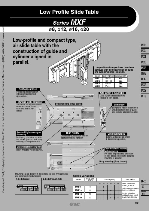
Series MXFø8, ø12, ø16, ø2020161281020305075100MXF20MXF16MXF12MXF8MXF8MXF12MXF16MXF2016 x 5818.5 x 6821 x 8027 x 92Low Profile Slide TableLow-profile and compact type, air slide table with the construction of guide and cylinder aligned in parallel.Low-profile and compactness have been achieved with the construction of guide and cylinder aligned in parallel.Model Height x Width (mm)Height comparison to MXS Stronger thread for mounting workHigh rigidityOptional portingReproducibility for mounting and dismountingAuto switch is mountableSlim bodyStandard stroke adjustmentReproducibility for mounting and dismountingNeat appearanceStroke can be adjusted at each stroke end within 5 mm each end and 10 mm is total.Insert thread for mounting work.Cross roller guide allows smooth operation without vibration.Lateral and axial piping from 2 directions is possible.Pin holes for positioning on bottom of slide allows precise and accurate mounting of actuator.Body mounting (Body tapped)Auto switch is recessed in the groove to save space.Low-profile has been achieved with the construction of guide and cylinder aligned in parallel.Body mounting (Body tapped)Protecting stopper section with cover realizes neat appearance.Positioning pin holes on table top allows precise and easy mounting to change workpiece.2. Body through-hole1. Body tappedMounting can be done from 2 directions top side (through-hole) and bottom side (body tapped).Bore size (mm)Auto switchStroke (mm)Series VariationsModelReed auto switch D-A9 , D-A9 V Solid state auto switch D-M9 , D-M9 V 2-color indicationsolid state auto switch D-M9 W, D-M9 WV133MXH MXU MXS MXQ MXF MXW MXJ MXP MXY MTSIndividual -XD- -XC o u r t e s y o f C M A /F l o d y n e /H y d r a d y n e ▪ M o t i o n C o n t r o l ▪ H y d r a u l i c ▪ P n e u m a t i c ▪ E l e c t r i c a l ▪ M e c h a n i c a l ▪ (800) 426-5480 ▪ w w w .c m a f h .c o m3-13-23-33-4123L 2+A 5L 3L 1Series MXFModel SelectionModel Selection StepFormula/Data Selection ExampleOperating ConditionsKinetic EnergyLoad FactorLoad factor of load massLoad factor of the static momentLoad factor of dynamic momentSum of the load factorsFind the kinetic energy E (J) of the load.Find the allowable kinetic energy Ea (J).Confirm that the kinetic energy of the load does not exceed the allowable kinetic energy.Use is possible if the sum of the load factors does not exceed 1.Enumerate the operating conditions considering the mounting position and workpiece configuration.• Model to be used • Type of cushion• Workpiece mounting position • Mounting orientation • Average speed Va (mm/s)• Load mass W (kg): Fig. (1)• Overhang Ln (mm): Fig. (2)E = -· W (-)2Collision speed V = 1.4 ·Va Ea = K·EmaxWorkpiece mounting coefficient K: Fig. (3)Max. allowable kinetic energy Emax: Table (1)Kinetic energy (E) Allowable kinetic energy (Ea)—∗12V1000∗) Correction factor (Reference values)Cylinder: MXF20-50Cushion: Rubber bumper Workpiece table mounting Mounting: Horizontal wall mounting Average speed: Va = 300 [mm/s]Allowable load: W = 0.5 [kg]L 1 = 10 mm L 2 = 30 mm L 3 = 30 mmRollingYawingPitchingYawing134C o u r t e s y o f C M A /F l o d y n e /H y d r a d y n e ▪ M o t i o n C o n t r o l ▪ H y d r a u l i c ▪ P n e u m a t i c ▪ E l e c t r i c a l ▪ M e c h a n i c a l ▪ (800) 426-5480 ▪ w w w .c m a f h .c o mSymbolAn (n = 1 to 6)E Ea EmaxLn (n = 1 to 3)M (Mp, My, Mr)Ma (Map, May, Mar)Me (Mep, Mey)Mea (Meap, Meay)Mmax (Mpmax, Mymax, Mrmax)VUnit mm J J J mm N·m N·m N·m N·m N·m mm/sSymbol Va W Wa We WmaxUnit mm/s kg kg kg kg ——————————MXF8MXF12MXF16MXF20100.56——————200.781.65————300.982.223.416.6650——3.345.699.1475————7.9613.70100——————18.271.00.70.50.40.30.2501002003005007001.00.70.50.40.30.250100200300500700MXF8MXF12MXF16MXF20MXF8MXF12MXF16MXF200.61 2 4WWWWK = 1K = 0.6MepWWMpWMpL 1A 1L 1A 2L 3A 2WMrWMrL 3A 5L 3A 6L 2A 3L 2A 4WMyWMyMeyL 2A 4MXF8MXF12MXF16MXF20A 16101011A 210111217A 36101011A 421232834A 521232834A 610111217SymbolTable (4) Maximum Allowable Moment: Mmax (N·m)Fig. (1) Load mass: W (kg)Fig. (2) Overhang: Ln (mm), Correction Values for Moment Center Distance: An (mm)Table (1) Maximum Allowable KineticEnergy: Emax (J)Table (2) Maximum AllowableLoad mass: Wmax (kg)Fig. (3) Workpiece MountingCoefficient: KTable (3) Moment Center Position DistanceCompensation Amount: An (mm)Pitch momentY aw momentRoll momentD y n a m i c m o m e n tS t a t i c m o m e n tNote) Static moment: Moment generated by gravityDynamic moment:Moment generated by impact whencolliding with stopperNote) No need to consider this load factor inthe case of using perpendicularly in a vertical position.T able mountingEnd plate mountingModelAllowable kinetic energyRubber bumper0.0270.0550.110.16ModelMaximum allowable load massNote) 16 mm for MXF8-10 only.ModelMoment center position distance compensation amount (Refer to Fig. (2).)Note)Note)Average speed Va (mm/s)Note) Use the average speed when calculating static moment.Use the collision speed when calculating dynamic moment.Average speed Va (mm/s)Collision speed V (mm/s)DefinitionCorrection values of moment center position distance Kinetic energyAllowable kinetic energyMax. allowable kinetic energy OverhangStatic moment (pitch, yaw, roll)Allowable static moment (pitch, yaw, roll)Dynamic moment (pitch, yaw)Allowable dynamic moment (pitch, yaw)Maximum allowable moment (pitch, yaw, roll)Collision speedDefinitionAverage speed Load massAllowable load mass Mass equivalent to impact Max. allowable load mass Load factorA llowable load mass coefficient Allowable moment coefficient Damper coeficientWorkpiece mounting coefficient ModelStroke (mm)135Low Profile Slide Table SeriesMXFMXHMXU MXS MXQ MXF MXW MXJ MXPMXY MTSIndividual -XD- -XC o u r t e s y o f C M A /F l o d y n e /H y d r a d y n e ▪ M o t i o n C o n t r o l ▪ H y d r a u l i c ▪ P n e u m a t i c ▪ E l e c t r i c a l ▪ M e c h a n i c a l ▪ (800) 426-5480 ▪ w w w .c m a f h .c o m10, 20, 3020, 30, 5030, 50, 7530, 50, 75, 100ø8ø12ø16ø20Nil S nMXF 1250M9BWø8ø12ø16ø208121620MXF A 16X11Nil X11X125 mm 15 mm 25 mm27∗ Lead wire length symbols: 0.5 m ·················Nil (Example) M9NW 1 m ·················M (Example) M9NWM 3 m ·················L (Example) M9NWL 5 m ·················Z (Example) M9NWZA96V A93V A90VM9NV M9PV M9BV M9NWV M9PWV M9BWV A96A93A90M9N M9P M9B M9NW M9PW M9BW 3-wire (NPN equivalent)—24 V24 V 2-wireN o3-wire (NPN)3-wire (PNP)2-wire 3-wire (NPN)3-wire (PNP)2-wire DC ACPerpendicularIn-line0.5(Nil)5(Z)—100 V 100 V or less ———————1(M)—————Diagnostic indication (2-color indication)5 V 12 V5 V,12 V12 V 5 V,12 V 12 V3(L)How to OrderMade to OrderRefer to page 137 for details.2 pcs. 1 pc. “n” pcs.Number of auto switches∗ For the applicable auto switch model, refer to the table below.Auto switchNilWithout auto switch (Built-in magnet)Bore size/Stroke (mm)How to Order Stroke Adjusting Bolt (Accessory)Applicable bore sizeAdjustment rangeStandard Option∗ -X12 (adjustable range 25 mm) is not available in Series MXF8/MXF12.Applicable Auto Switch /Refer to pages 1719 to 1827 for the detailed specifications of auto switches.Special functionT ype Electrical entry Wiring (Output)Load voltage Auto switch model Lead wire length (m)Applicable load Pre-wiredconnectorI n d i c a t o r l i g h tIC circuit ICcircuit ICcircuit IC circuit Relay,PLC Relay,PLC————Y e sY e s GrommetGrommetR e e d s w i t c hS o l i d s t a t e s w i t c h∗ Solid state auto switches marked with “ ” are produced upon receipt of order.∗ Since there are other applicable auto switches than listed, refer to page 145 for details.∗ For details about auto switches with pre-wired connector, refer to pages 1784 and 1785.∗ Auto switches are shipped together (not assembled).136Low Profile Slide TableSeries MXFLow Profile Slide TableC o u r t e s y o f C M A /F l o d y n e /H y d r a d y n e ▪ M o t i o n C o n t r o l ▪ H y d r a u l i c ▪ P n e u m a t i c ▪ E l e c t r i c a l ▪ M e c h a n i c a l ▪ (800) 426-5480 ▪ w w w .c m a f h .c o mSymbolMXF 8MXF 120.060.040.02102030400.08MXF8-30MXF8-20MXF8-10102030MXF8-10MXF8-20MXF8-300.030.020.01102030400.04MXF8-20MXF8-30MXF8-100.030.020.010000.060.040.02204060MXF12-30MXF12-20MXF12-500.080.10204060MXF12-30MXF12-50MXF12-2020406080MXF12-30MXF12-20MXF12-500.080.060.040.020.060.040.02000Lr = 20 mmLr = 30 mmFAALrTable Deflection (Reference Values)Table displacement due to pitch moment loadTable displacement due to yaw moment loadTable displacement due to roll moment loadT able displacement when loads are applied to the section marked with the arrow at the full stroke.T able displacement when loads are applied to the section marked with the arrow at the full stroke.T able displacement of section A when loads are applied to the section F with the slide table retracted.Load (N)T a b l e d i s p l a c e m e n t a m o u n t (m m )Load (N)T a b l e d i s p l a c e m e n t a m o u n t (m m )Load (N)T a b l e d i s p l a c e m e n t a m o u n t (m m )Load (N)T a b l e d i s p l a c e m e n t a m o u n t (m m )Load (N)T a b l e d i s p l a c e m e n t a m o u n t (m m )Load (N)T a b l e d i s p l a c e m e n t a m o u n t (m m )138Series MXFC o u r t e s y o f C M A /F l o d y n e /H y d r a d y n e ▪ M o t i o n C o n t r o l ▪ H y d r a u l i c ▪ P n e u m a t i c ▪ E l e c t r i c a l ▪ M e c h a n i c a l ▪ (800) 426-5480 ▪ w w w .c m a f h .c o mMXF 16MXF 200.080.160.040.120.2020406080100MXF16-50MXF16-30MXF16-751206004080100MXF16-75MXF16-50MXF16-3020406080100MXF16-75MXF16-50MXF16-300.010.030.050.060.020.040.070.010.030.050.060.020.040.07000.160.240.08MXF20-100MXF20- 75MXF20- 50MXF20- 300.120.200.28MXF20-100MXF20-75MXF20-50MXF20-30MXF20-100MXF20- 30MXF20- 50MXF20- 750.100.080.040.020.060.040.020.0650100150408012024020016020050100150200000Lr = 40 mmLr = 50 mmFAALr200.04Load (N)T a b l e d i s p l a c e m e n t a m o u n t (m m )Load (N)T a b l e d i s p l a c e m e n t a m o u n t (m m )Load (N)T a b l e d i s p l a c e m e n t a m o u n t (m m )Load (N)T a b l e d i s p l a c e m e n t a m o u n t (m m )Load (N)T a b l e d i s p l a c e m e n t a m o u n t (m m )Load (N)T a b l e d i s p l a c e m e n t a m o u n t (m m )Table displacement due to pitch moment loadTable displacement due to yaw moment loadTable displacement due to roll moment loadTable displacement when loads are applied to the section marked with the arrow at the full stroke.Table displacement when loads are applied to the section marked with the arrow at the full stroke.Table displacement of section A when loads are applied to the section F with the slide table retracted.The graphs below show the table displacement when the static moment load is applied to the table. The graphs do not show the loadable mass. Refer to the Model Selection for the loadable mass.139Low Profile Slide Table SeriesMXFMXHMXU MXSMXQ MXF MXW MXJ MXPMXYMTSIndividual -XD- -XC o u r t e s y o f C M A /F l o d y n e /H y d r a d y n e ▪ M o t i o n C o n t r o l ▪ H y d r a u l i c ▪ P n e u m a t i c ▪ E l e c t r i c a l ▪ M e c h a n i c a l ▪ (800) 426-5480 ▪ w w w .c m a f h .c o mMXF8-PS MXF12-PS MXF16-PS MXF20-PS8121620MXF-A827MXF-A827-X11MXF-A1227MXF-A1227-X11MXF-A1627MXF-A1627-X11MXF-A1627-X12MXF-A2027MXF-A2027-X11MXF-A2027-X125155155152551525172723.533.526.536.546.53040506781222.534M4 x 0.7M5 x 0.8M6 x 1M8 x 1MXF8MXF12MXF16MXF20ABCMAMCB w!9!8i!5u !7q!0!6t!3!4!2rey o!1No.123456Description Material Note Component PartsDescription Material NoteNo.16171819Component Parts789101112131415Body Table End plate Rail Guide RodPiston assembly Seal support Head capFloating bushing OrificeRoller stopper Cylindrical roller Roller spacer Rod bumperAluminum alloy Aluminum alloy Aluminum alloy Carbon tool steel Carbon tool steel Stainless steel—Brass Resin Stainless steelBrass Stainless steel High carbon chrome bearing steelResin PolyurethaneHard anodized Hard anodized Hard anodized Heat treated Heat treated With magnet Electroless nickel plated Electroless nickel plated Adjust bumper Piston seal Rod seal O-ring PolyurethaneNBR NBR NBRReplacement Parts: Seal KitBore size (mm)Kit no.Set of nos. above !7 to !9∗ Seal kit includes !7, !8, !9. Order the seal kit, based on each bore size.ContentsReplacement Part: Grease PackApplied part GuideCylinderGrease pack part no.GR-S-005 (5 g) GR-S-010 (10 g)GR-S-020 (20 g)GR-S-050 (50 g)GR-L-005 (5 g) GR-L-010 (10 g)GR-L-020 (20 g)GR-L-050 (50 g)Applicable sizeModel Stroke adjustable range (mm)140Series MXFConstructionDimensions: Stroke Adjusting BoltC o u r t e s y o f C M A /F l o d y n e /H y d r a d y n e ▪ M o t i o n C o n t r o l ▪ H y d r a u l i c ▪ P n e u m a t i c ▪ E l e c t r i c a l ▪ M e c h a n i c a l ▪ (800) 426-5480 ▪ w w w .c m a f h .c o m14618211358F (Equal pitch)A4N x M3 x 0.5 thread depth 6.5(Insert)3H 9 d e p t h 3+0.02503H 9 d e p t h 3+0.0250486A´GH192 x M3 x 0.5 thread depth 6159.54.584.74 x ø6.54.74 x ø3.24 x M4 x 0.70.315M(T able length)8164.5Max. 9J Z ZZ2.4821HG 4ModelMXF8-10MXF8-20MXF8-30F202626G13.514.514.5H222640J212641M495469Z49.554.569.5ZZ586378N446Operating port 2 x M3 x 0.510.5353120.5Note) If long bolts are used, they cantouch the guide block and cause malfunction, etc.Refer to the Specific ProductPrecautions.Stroke adjuster at extension end Stroke adjuster at retraction endWidth across hexagon socket hole 2Width across flats 6ø3H9 +0.0250 depth 3N2( – 1) x F ∗Note)Blanking plug (M-3P 2 points)Possible to use asoperating port 2 x M3 x 0.5N2∗ ( – 1): The number of pitches Section AA´ø3H9 depth 3+0.0250(mm)141Dimensions: MXF8Low Profile Slide Table SeriesMXFMXH MXU MXS MXQ MXFMXWMXJ MXP MXYMTSIndividual -XD- -XC o u r t e s y o f C M A /F l o d y n e /H y d r a d y n e ▪ M o t i o n C o n t r o l ▪ H y d r a u l i c ▪ P n e u m a t i c ▪ E l e c t r i c a l ▪ M e c h a n i c a l ▪ (800) 426-5480 ▪ w w w .c m a f h .c o mModelMXF12-20MXF12-30MXF12-50N446H223065I111213J364580M6575111Z6575111ZZ76861225869.85.52010254A20.5231668A´25H168.5204M(Table length)10J Z ZZ318.55.5H25230.3176.54 x M4 x 0.76.54 x ø6.54 x ø3.2I10.54524.535Stroke adjuster at extension end Stroke adjuster at retraction end Width across hexagon socket hole 2.5Width across flats 72 x M3 x 0.5 thread depth 6ø3H9 +0.0250 depth 3N 2( – 1) x 25∗N x M3 x 0.5 thread depth 5.5(Insert)Note)Blanking plug (M-5P 2 points)Possible to use asoperating port 2 x M5 x 0.83H 9 d e p t h 3+0.0250Max. 10.5Operating port 2 x M5 x 0.83H 9 d e p t h 3+0.025ø3H9depth 3+0.0250(mm)Note) If long bolts are used, they cantouch the guide block and cause malfunction, etc.Refer to the Specific ProductPrecautions.N2∗ ( – 1): The number of pitches Section AA´142Series MXFDimensions: MXF12C o u r t e s y o f C M A /F l o d y n e /H y d r a d y n e ▪ M o t i o n C o n t r o l ▪ H y d r a u l i c ▪ P n e u m a t i c ▪ E l e c t r i c a l ▪ M e c h a n i c a l ▪ (800) 426-5480 ▪ w w w .c m a f h .c o mModelMXF16-30MXF16-50MXF16-75N466G292939H255545NN446I121213J5080125M83113159Z83113159ZZ94124170243558027.520HG2312.55.511.5182597M(Table length)100.319.5J Z ZZ3HG 27.556876.76.7N N x ø8NN x M5 x 0.8N N x ø4.2IAA´12.55241.528.521Width across hexagon socket hole 3Width across flats 8Stroke adjuster at retraction end Stroke adjuster at extension end2 x M4 x 0.7 thread depth 10ø4H9 +0.0300 depth 4N 2( – 1) x 35∗NN 2( – 1) x H 4H 9d e p t h 4 +0.030 0N x M4 x 0.7 thread depth 6.5(Insert)Note)Blanking plug (M-5P 2 points)Possible to use asoperating port 2 x M5 x 0.8Operating port 2 x M5 x 0.8Max. 9ø4H9+0.030depth 44H 9d e p t h 4 +0.030 0Section AA´N2∗ ( – 1): The number of pitches(mm)Note) If long bolts are used, they cantouch the guide block and cause malfunction, etc.Refer to the Specific ProductPrecautions.143Dimensions: MXF16Low Profile Slide Table SeriesMXFMXHMXU MXS MXQMXF MXWMXJ MXP MXY MTSIndividual-XD- -XC o u r t e s y o f C M A /F l o d y n e /H y d r a d y n e ▪ M o t i o n C o n t r o l ▪ H y d r a u l i c ▪ P n e u m a t i c ▪ E l e c t r i c a l ▪ M e c h a n i c a l ▪ (800) 426-5480 ▪ w w w .c m a f h .c o mModelMXF20-30MXF20-50MXF20-75MXF20-100N4466G29364059H30454560NN4466J5777125175M91113162211Z91113162211ZZ104126175224286069233.525A789HG0.525M(T able length)1227712Z ZZ3HG 33.562230122611.5135.58.58.5N N x ø8NN x M5 x 0.8N N x ø4.2J 641551.537Width across hexagon socket hole 4Width across flats 12Stroke adjuster at retraction end Stroke adjuster at extension end2 x M5 x 0.8 thread depth 12N2( – 1) x 60∗ø5H9 +0.030depth 5NN2( – 1) x H 5H 9d e p t h 5 +0.030 0Note)Blanking plug (M-5P 2 points)Possible to use asoperating port 2 x M5 x 0.8Operating port 2 x M5 x 0.8Max. 9.5Section AA´N2∗ ( – 1): The number of pitches A´Note) If long bolts are used, they cantouch the guide block and cause malfunction, etc.Refer to the Specific ProductPrecautions.ø5H9+0.030depth 55H 9d e p t h 5 +0.030 0(mm)144Series MXFDimensions: MXF20N x M5 x 0.8 thread depth 9.5(Insert)C o u r t e s y o f C M A /F l o d y n e /H y d r a d y n e ▪ M o t i o n C o n t r o l ▪ H y d r a u l i c ▪ P n e u m a t i c ▪ E l e c t r i c a l ▪ M e c h a n i c a l ▪ (800) 426-5480 ▪ w w w .c m a f h .c o mReed Auto Switch: D-A90, D-A93, D-A96, D-A90V, D-A93V, D-A96VSolid State Auto Switch: D-M9B, D-M9N, D-M9P, D-M9BW, D-M9NW, D-M9PWSolid State Auto Switch: D-M9BV, D-M9NV, D-M9PV, D-M9BWV, D-M9NWV, D-M9PWVEABMXF8MXF12MXF16MXF209.51217.219.41010———20513.1——301013.115.820.750—29.125.822.775——46.846.2100———70.710———20——3050—75——100———BE MXF8MXF12MXF16MXF2013.51621.223.41014———20917.1——301417.119.824.750—33.129.826.775——50.850.2100———74.710———20——3050—75——100———BE MXF8MXF12MXF16MXF2013.51621.223.41014———20917.1——301417.119.824.750—33.129.826.775——50.850.2100———74.7106———2019.1——3069.111.816.750—25.121.818.775——42.342.2100———66.7BE 48(5.5)3(0.5)11.1(8.6)8(5.5)11.1(8.6)13.8(11.3)18.7(16.2)27.1(24.6)23.8(21.3)20.7(18.2)44.8(42.3)44.2(41.7)68.7(66.2)–17.147.19.814.723.119.816.740.840.264.7AAA(mm)(mm)(mm)D-A9 (V)D-M9 , M9 V D-M9 W, M9 WV84.5312531664.52075Tightening Torque of Auto Switch Mounting Screw Tightening torque 0.10 to 0.200.05 to 0.15D-A9 (V)D-M9 (V)D-M9 W(V)(N ·m)Other than the models listed in “How to Order”, the following auto switches are applicable.∗ Normally closed (NC = b contact) solid state auto switches (D-F9G/F9H types) and solid state auto switch D-F8 are also available.For details, refer to pages 1745 and 1746.Auto Switch Mounting Tool• When adjusting the auto switch mounting screw (included with auto switch), use a watchmaker´s screwdriver with a handle about 5 to 6 mm in diameter.Tightening TorqueStroke StrokeModel Stroke StrokeModel Stroke StrokeModel ∗ ( ): Denotes the values of D-A93.Note) Adjust the auto switch after confirming the operating conditions in the actual setting.Operating RangeApplicable bore size (mm)Auto switch modelAuto switch modelAuto Switch Mounting CautionAuto switch mounting screw (included with auto switch)Watchmaker´s screwdriverAuto switch∗ Since the operating range is provided as a guideline including hysteresis, it cannot be guaranteed (assuming approximately ±30 dispersion). It may vary substantially depending on an ambient environment.145Low Profile Slide Table SeriesMXFAuto Switch Proper Mounting Position (Detection at Stroke End)MXH MXU MXS MXQMXF MXW MXJ MXP MXYMTSIndividual -XD--XC o u r t e s y o f C M A /F l o d y n e /H y d r a d y n e ▪ M o t i o n C o n t r o l ▪ H y d r a u l i c ▪ P n e u m a t i c ▪ E l e c t r i c a l ▪ M e c h a n i c a l ▪ (800) 426-5480 ▪ w w w .c m a f h .c o mSeries MXFSpecific Product PrecautionsBe sure to read before handling. Refer to front matters 42 and 43 for Safety Instructions and pages 3 to 11 for Actuator and Auto Switch Precautions.MXF8MXF12MXF16MXF20M4 x 0.7M4 x 0.7M5 x 0.8M5 x 0.82.12.14.44.44.76.56.78.5MXF8MXF12MXF16MXF20M3 x 0.5M3 x 0.5M4 x 0.7M4 x 0.71.21.22.82.84.76.56.78.5MXF8MXF12MXF16MXF20M3 x 0.5M3 x 0.5M4 x 0.7M5 x 0.80.90.92.14.4661012MXF8MXF12MXF16MXF20M3 x 0.5M3 x 0.5M4 x 0.7M5 x 0.80.90.92.14.46.55.56.59.5LLLLMountingCautionCautionCautionPositioningSelection1.Do not scratch or dent the mounting side of the body, table or end plate. It causes play in the guide section and increases sliding resistance.2.Do not scratch or dent on the forward side of the rail or guide. It will result in looseness of the guide section and increased sliding resistance.3.Keep away from objects which are influenced by magnets.As the piston part has magnets built-in, do not allow close contact with magnetic disks, magnetic cards or magnetic tapes. Data may be erased.4.When mounting the body, use screws with appropriate length and do not exceed the maximum tightening torque.Tightening with a torque above the limit could malfunction. Whereas tightening insufficiently could result in misalignment or come to a drop.5.Be careful when adjusting stroke not to allow cylinder end plate to bottom out against cylinder body.1. The positioning hole on the table and on the bottom of the body does not have the same center. Positioning hole is meant to be for reproducibility for mounting and dismounting.1.If intermediate stop by external stopper is done, avoid ejection.If ejection occurs, it may cause damage.In the case the slide table is stopped at an intermediate position by an external stopper then forwarded to the front, return the slide table to the back for just a moment to retract the stopper, then supply pressure to the opposite port to operate slide table.2.Do not use it in such a way thatexcessive external force or impact force could work on it.This could result in damage.Mounting of BodyMounting of WorkpieceThe slide table can be mounted from 2 directions. Select the best direction according to your application.Work can be mounted on two sides of the body.1. Body Tapped2. Body Through-holeModel Bolt Maximumtightening torque (N·m)Maximum screw-indepth L (mm)Model Bolt Maximumtightening torque (N·m)Maximum screw-indepth L (mm)Model Bolt Maximumtightening torque (N·m)Maximum screw-indepth L (mm)Model Bolt Maximumtightening torque (N·m)Maximum screw-indepth L (mm)0.02 mm or less of flatness is recommended for the body mounting surface.An uneven mounting surface of a workpiece or a base may cause vibration or increase sliding resistance.Caution1. Front Mounting2. Top MountingFixing bolt for guideCautionTo prevent the workpiece holding bolts from touching the guide holding bolts, use bolts that are 0.5 mm or more shorter than the maximum screw-in depth.If the bolts are too long, they hit the end plate and may cause malfunctions.146C o u r t e s y o f C M A /F l o d y n e /H y d r a d y n e ▪ M o t i o n C o n t r o l ▪ H y d r a u l i c ▪ P n e u m a t i c ▪ E l e c t r i c a l ▪ M e c h a n i c a l ▪ (800) 426-5480 ▪ w w w .c m a f h .c o m。
AO4882;中文规格书,Datasheet资料

415
pF
112
pF
11
pF
1
2.2 3.5
Ω
SWITCHING PARAMETERS
Qg(10V) Total Gate Charge
6.5 12 nC
Qg(4.5V) Total Gate Charge
Qgs
Gate Source Charge
VGS=10V, VDS=20V, ID=8A
3
6
nC
VGS=4.5V, ID=4A
21
27 mΩ
gFS
Forward Transconductance
VDS=5V, ID=8A
33
S
VSD
Diode Forward Voltage
IS=1A,VGS=0V
0.75 1
V
IS
Maximum Body-Diode Continuous Current
2.5
1.2
nC
Qgd
Gate Drain Charge
1.1
nC
tD(on)
Turn-On DelayTime
4
ns
tr
Turn-On Rise Time
VGS=10V, VDS=20V, RL=2.5Ω,
3
ns
tD(off)
Turn-Off DelayTime
RGEN=3Ω
15
ns
tf
Turn-Off Fall Time
ID=250µA, VGS=0V
40
V
IDSS
Zero Gate Voltage Drain Current
VDS=40V, VGS=0V
MX Sheet 版本1操作手册(入门篇)

注意
三菱电机公司不对在本手册中提及的基于 Windows 的软件产品提供保证。 三菱电机保有此软件的版权。 未得到三菱电机事先授权,不得以任何形式翻录或复制本手册中的内容。 三菱电机公司在修订本手册时,尽量同时对所有软硬件的内容进行更新。 确保一套软件只用在一台个人计算机上。 基于软件许可协议范围内,允许用户使用本软件(包括本手册)。
A-5
A-5
关于手册
相关手册
以下列出的是和本软件相关的手册,在订购这些手册时请参阅下表。
手册名
MX Sheet 版本 1 操作手册
介绍 MX Sheet 操作流程、设置和使用方法。
(另购)
MX Component Version 3 Operating Manual
介绍 MX Component 版本各效用的设置和使用方法。
[设计上的说明] ! 危险
在 PLC 系统外部设立一个安全电路,以确保在修改运行中的 PLC 数据或在个人计算机上控制 PLC 的状态时,整个系统也能安全工作。 另外,从外围设备连接到运行中的 PLC CPU 时,由于线缆质量低劣可能发生通讯错误,请结合 矫正操作处理通讯错误。
[操作时注意事项] ! 注意
A-6
A-6
术语定义
本手册中所用的术语有如下的定义和含义。
(1)逻接逻目辑辑标站站号进号是行指通这讯样所的需的数信据组息。群的号码,此数据组群为通讯设置实用中所设置的与连
ϾҎ䅵ㅫᴎ
4+&38
І㸠䗮ֵ &20 ᯊ䯈⑶ߎᳳ䯈
⊶⡍⥛Ӵ䕧ࠊ
ᇚࠄ䗮䆃Ⳃᷛキ&38Ўℶⱘ᠔᳝䖲ᇍ䈵ⱘֵᙃЎϔϾᭈԧ᭄ᑊߚ䜡㒭ᅗⱘϔϾ䘏䕥キোDŽ
1 概述
1- 1 到 1- 2
MXP7000 商品说明书

MISSION-CRITICAL CONVERGED TETRA AND LTE PORTABLE DEVICEThe MXP7000 provides versatile communications. It delivers mission-critical TETRA and 4G LTE broadband voice and data communications, in a secure and rugged Android device.It’s easy to use and operate the MXP7000. The large push-to-talk button lets users connect instantly, and the field-swappable battery helps them stay connected longer. Innovative audio technology enables your personnel to hear and be heard clearly, even in noisy and windy conditions. It has a 5-inch touchscreen and the device can run applications for optimal workforce productivity.The MXP7000 is easy to deploy and manage, and it supports Bluetooth® 5.1 for data transfer. It has a GCAI-mini connector, so you can provide your teams with accessories tailored to their needs.No matter their mission, the MXP7000is a device that helps your teams getthe job done.MXP7000TETRA AND LTE PORTABLE DEVICE YOUR APPS. YOUR COMMS. YOUR TEAM. TOGETHERGENERAL SPECIFICATIONSDimensions Height: 210mm (with antenna) Height: 150mm (without antenna) Width: 80mmDepth: 29.85mm (with battery)Weight440g (with battery and antenna) Battery Options5600mAh IMPRES™ 2Housing Colour BlackGreen (selected models)Display 5.0”, 1280 x 720 Capacitive, touch-screen with Corning® Gorilla® glassSupports use with disposable and combat glovesControls Large Push-to-talk button Emergency buttonDual function rotary knob 2 configurable side buttonsMemory 4GB RAM64GB Internal Storage Supports microSDSIM Slots TETRA SIM: 2FF (Mini SIM) LTE: 4FF (Nano SIM)Camera Rear 13MP, with integrated flash Front 8MPVideo Recording Quality1080p at 60 fpsSensors Proximity Ambient Light Accelerometer Barometer GyroscopeE-CompassPorts GCAI-mini USB-CDEVICE SECURIITYUser Authentication PIN or passwordKey Storage Hardware-backed encryption with Trusted Execution Environment (TEE)Trusted Boot Process Included with the use of tamper resistant hardware OS Hardening Android OS hardening and SELinux access controlAuditing Auditing / logging functionality, with security logs captured and stored in a secured mannerData-at-Rest Using Android’s AES256 File Based Encryption Data-in-Transit Encryption with IPSec VPN supportSecured Device Management With the use of Integrated Terminal Management (iTM) solutionRestricted Recovery Mode Included to avoid unauthorised access to features AUDIOAudio Power at Rated2WAudio Distortion at Rated<1%Audio Power at Maximum3WMax loudness99PhonNoise supression Adaptive Multi-Microphone Beam-Forming Number of Microphones3 dedicated + 1 loudspeaker as microphone TETRA SERVICEAuthentication Infrastructure initiated and made mutual by radio terminal Air Interface Encryption- AlgorithmsTEA 1, TEA 2, TEA 3Protocols - Security ClassesClass 1 (Clear)Class 2 (SCK)Class 3 (DCK/CCK, OTAR-CCK, OTAR-SCK)Class 3G (GCK, OTAR-GCK)End-to-End Encryption SIM based encryption including BSIOther Security FeaturesTemporary disable (stun)Permanent disable (either ETSI standard orcustomer restorable)CONNECTIVITYBluetooth Versions Supported Bluetooth 5.1 (data transfer only)Bluetooth Profiles Generic Attribute (GATT)Attribute Protocol (ATT)Generic Access Profile (GAP)Serial Port Profile (SPP)Personal Area Networking Profile (PAN) Object Push Profile (OPP)Headset Profile (HSP)LOCATION SERVICESConstellation Supported GPS, aGPS, Galileo, GLONASS, BDS (BeiDou) GNSS Antenna Internal antennaGNSS Tracking Sensitivity GPS:-158dBm (50% Fix losses) -162dBm (typical)Horizontal Accuracy, 2D <5m (95% probable, -130dBm) TTFF Cold Start<60 sec (95% probable at -130dBm) ProtocolsETSI LIP (short and long), Motorola Solutions LRRP KEY FEATURES & SETTINGSTalkgroup Management User friendly, flexible, fast and efficient interface TalkgroupsTMO folders: up to 256, TMO talkgroups: up to 10000DMO folders: up to 128, DMO talkgroups: up to 2000 Favourite Talkgroup Folders Up to 3Contacts Management Rapid search to find the contact easilyContacts Up to 1000 contactsMultiple Dialling Methods Dialling direct, scroll and select via touchscreenCall Alert Vibrate alert and set ringtones via Android SettingsFall Alert (Man-down)Triggers an emergency alert if the device is continuouslytilted beyond a pre-defined angleMessage ManagementDistinct folders for each message type forflexible message managementText Message ListUp to 200 entries (short messages)At least 20 entries for outbox(long messages up to 1000 characters)At least 10 entries for inbox(long messages up to 1000 characters)Status ListUp to 100 user-defined messagesAssignable to One Touch ButtonsText Entry Touchscreen for ease of useTransmit Inhibit Disables TETRA transmit and puts device into Airplane Mode 1 TETRA communications is still availableDEVICE MANAGEMENT SOLUTIONSIntegrated Terminal Management (iTM)Supports iTM version 8.0 onwardsENVIRONMENTAL SPECIFICATIONSOperating Temperature 2-20°C to + 60°C Storage Temperature -40°C to +85°CHumidity (High) , Low and High Temperature ETSI 300 019-1-7 class 7.3E Shock (bumps & shock), vibration (random)ETSI 300-019 1-7 class 5M3Dust and Water Ingress ProtectionBlack model: IP68 per IEC 60529Green model: IP67 per IEC 60529 Compliance to US Military Standard 810See table to the right2Performance may be limited when operating at extreme temperatures.US MILITARY STANDARD MATRIXMethodProc/CatLow Pressure 500.6II High Temperature 501.7I/A1,II Low Temperature 502.7I,II Thermal Shock 503.7I-C Solar Radiation 505.7I/A1Humidity 507.6II / AggravatedSalt Fog509.7-Blowing Sand 510.7II Vibration 514.8I/Cat 24,II/Cat 5Shock 3516.8I,IV,VI3Drop test is covered as part of Shock Method 516.8 Proc IV, VIMotorola Solutions UK Limited, Nova South, 160 Victoria Street, London, SW1E 5LB.All specifications are subject to change without notice.MOTOROLA, MOTO, MOTOROLA SOLUTIONS and the Stylised M Logo are trademarks or registered trademarks of Motorola Trademark Holdings, LLC and are used under licence. The Bluetooth ® word mark and logos are registered trademarks owned by Bluetooth SIG, Inc. and any use of such marks by Motorola Solutions, Inc. is under licence. All other trademarks are the property of their respective owners. © 2023 Motorola Solutions, Inc. All rights reserved. (09-23)For more information, please visit us at /mxp7000。
MXP4004BT,MXP4004BE,MXP4004BF (S23) Preliminary Datasheet Dec10-13

40V N-Channel MOSFETApplications:● Power Supply I D ● DC-DC Converters 170A● DC-AC InvertersFeatures:● Lead Free● Low R DS(ON) to Minimize Conductive Loss ● Low Gate Charge for Fast Switching Application ● Optimized V (BR)DSS RuggednessOrdering InformationPackage BrandTO220 Pin Definition and Inner CircuitTO263-2L TO263-3LAbsolute Maximum RatingsT C =25℃unless otherwise specifiedSymbolValueUnitV DSS 40V 17080I DM 679P D 231W V GS+/-20V T J and T stg-55 to 175℃Avalanche CharacteristicsT C =25℃unless otherwise specifiedSymbolValueUnitI ASFigure 9AThermal ResistanceSymbolMaxUnitR θJC 0.65℃/W R θJA62℃/WThermal Resistance, Junction-to-AmbientParameter Thermal Resistance, Junction-to-Case Power Dissipation Single Pulse Avalanche CurrentParameter Operating Junction and Storage Temperature RangeR DS(ON)(MAX)Silicon LimitedV DS 40V 3m ΩParameter Drain-to-Source Voltage Continuous Drain CurrentPackage Limited200mJ MXP4004BT I DMXP4004BF MXP4004BEA Pulsed Drain Current @V GS =10V Gate-to-Source VoltagePark Number MXPE AS ①Single Pulse Avalanche Energy(V DS =20V, V GS =10V, Rg=25Ω, L=1mH)40V N-Channel MOSFET OFF CharacteristicsT J =25℃unless otherwise specified SymbolMin Typ Max UnitV (BR)DSS 40--V --1--100--100--100ON CharacteristicsT J =25℃unless otherwise specified SymbolMin Typ Max UnitR DS(ON)- 2.33.0m ΩV GS(th)2-4VDynamic CharacteristicsT J =25℃unless otherwise specified SymbolMin Typ Max UnitCiss -5016-Coss -787-Crss -292-Qg -74-Qgs -23-Qgd -26-Td(on)-18.7-Tr -67.1-Td(off)-48.8-Tf -31-Source-Drain Diode Characteristics T J =25℃unless otherwise specifiedSymbolMinTypMaxUnitV SD -- 1.2V Trr -51.6-ns Qrr-35.1-nCGate-to-Source Charge Total Gate Charge Gate-to-Drain ("Miller") Charge Static Drain-to-Source On-ResistanceI GSSGate-to-Source Forward Leakage nAV GS =+20V Gate-to-Source Reverse LeakageV GS = -20VI DSS Drain-to-Source Leakage Current uA V DS =32V, V GS =0VV DS =32V, V GS =0V, T J =125 ℃I S =80A, V GS =0V nsV DD =20V, I D =40A,V GS =10V, R G =10Ω, R L =0.5ΩV DD =20V, I D =80A, V GS =10VTest ConditionsDrain-to-Source Breakdown VoltageV GS =0V, I D =250uA V GS =0V, V DS =20V,f=1.0MHz Output Capacitance Reverse Transfer Capacitance Parameter pFPublished by MaxPower Semiconductor Inc.V GS =10V, I D =80A ParameterTest ConditionsInput Capacitance Test ConditionsTurn-off Delay Time Fall Time Diode Forward Voltage Reverse Recovery Time Is=80A, di/dt=100A/μsReverse Recovery ChargeParameterTest ConditionsGate Threshold VoltageV GS =V DS , I D =250uATurn-on Delay Time Rise Time Parameter nC40V N-Channel MOSFET40V N-Channel MOSFET40V N-Channel MOSFETTO220Published by MaxPower Semiconductor Inc. UNIT : mm1. Outline DimensionPublished by MaxPower Semiconductor Inc.TO263-2L1. Outline DimensionTO263-3L1. Outline DimensionPublished by MaxPower Semiconductor Inc.UNIT : mmDisclaimers:MaxPower Semiconductor Inc. (MXP) reserves the right to make changes without notice in order to improve reliability, function or design and to discontinue any product or service without notice. Customers should obtain the latest relevant information before orders and should verify that such information is current and complete. All products are sold subject to MXP's terms and conditions supplied at the time of order acknowledgement.MaxPower Semiconductor Inc., its affiliates, agents, and employees, and all persons acting on its or their behalf, disclaim any and all liability for any errors, inaccuracies or incompleteness contained herein or in any other disclosure relating to any product.MaxPower Semiconductor Inc. disclaims any and all liability arising out of the use or application of any product described herein or of any information provided herein to the maximum extent permitted by law. The product specifications do not expand or otherwise modify MXP's terms and conditions of purchase, including but not limited to the warranty expressed therein, which apply to these products.MaxPower Semiconductor Inc. warrants performance of its hardware products to the specifications at the time of sale, testing, reliability and quality control are used to the extent MXP deems necessary to support this warrantee. Except where agreed upon by contractual agreement, testing of all parameters of each product is not necessarily performed.MaxPower Semiconductor Inc. does not assume any liability arising from the use of any product or circuit designs described herein. Customers are responsible for their products and applications using MXP's components. To minimize risk, customers must provide adequate design and operating safeguards.MaxPower Semiconductor Inc. does not warrant or convey any license to any intellectual property rights either expressed or implied under its patent rights, nor the rights of others. Reproduction of information in MXP's data sheets or data books is permissible only if reproduction is without modification or alteration. Reproduction of this information with any alteration is an unfair and deceptive business practice.MaxPower Semiconductor Inc. is not responsible or liable for such altered documentation. Resale of MXP's products with statements different from or beyond the parameters stated by MaxPower Semiconductor Inc. for that product or service voids all express or implied warrantees for the associated MXP product or service and is an unfair and deceptive business practice. MaxPower Semiconductor Inc. is not responsible or liable for any such statements.Published by MaxPower Semiconductor Inc.。
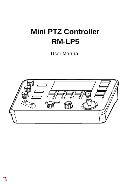
魅玛轻型迷你PTZ控制器RM-LP5用户手册说明书
Mini PTZ Controller RM-LP5User ManualParameters & Specs Communication & Control Interface Camera Control or Operation Control Signal FormatPower Supply and ConsumptionPhysical & Others Description of Button & Knob FunctionInterface Function and Connection Diagram Upgrade Interface RS422/RS485 Interface RS232 Interface LAN Interface12V DC Power InterfaceSystem Menu Operation Instructions System Menu Function Explanation Keyboard System Menu System Setting Comm Setting Ethernet SettingPassword SettingSystem Menu Guide Products DimensionsContent2 2 2 2223 7 7788910 10 10 10 11 11 12 12 13④⑤⑪⑮①This Rotation Knob which was to adjustment the Camera Exposure Parameter or Red Gain Value, Turn Right Rotation was to changed the valued Increased, Turn Left Rotation was changed the Valued Decreased.②This Rotation Knob which was to adjustment the Camera Exposure Parameter or Blue Gain Value, Turn Right Rotation was to changed the valued Increased, Turn Left Rotation was changed the Valued Decreased.③This Rotation Knob which was to adjustment the Camera Exposure Parameter, Turn Right Rotation was to changed the valued Increased, Turn Left Rotation was changed the Valued Decreased.④LED Display, Real-time display of items and parameter values of adjusted by " knob ①".⑤LED Display, Real-time display of items and parameter values of adjusted by " knob ②".⑥LED Display, Real-time display of items and parameter values of adjusted by " knob ③".⑦Zoom Bridge KeyIt is used to control the camera to Zoom In/Out, for example, press the TELE end of the bridge key, the camera will Zoom in the TELE direction object, When you Press with more Large Pressure, then the Zoom Speed changed more Faster.⑧ Focus Function ZoonWhen the Backlight of [AUTO]Button is Light up, it means that the current focusing mode is the automatic; When the Backlight of [AUTO] Button is Light Off, it means that Current Focus Mode is changed to Manual. User can Press this button to switch the mode.[OPT key] is used to trigger the single focus of the camera.At the same time, the camera enters the one-shot auto focus mode.⑨PTZ Speed Adjustment KnobThis knob is used to adjust the speed of Camera Pan, Tlit and Zoom, with a total of 7 gears.The Current Gear will be display at Led Display. The Gear Value is more small then the pan/tilt rotation speed or the zoom speed of the camera controlled by the keyboard will be more Slowly.⑩ 2-Aixs JoystickThe joystick supports control camera to Up/Down, Left and Right movement. When the camera or keyboard menu is opened, the joystick is used to control the menu cursor Up/Down,Left/Right movement and modify parameters.⑪ Channel Button Zone[ CAM1 ] to [ CAM5 ] are shortcut keys for camera channels, which can be Freely switched and selected according to your need. When you select any camera channel, the backlight of the corresponding camera channel will be light up in green, and all the parameters and settings of the keyboard will be changed to the current Channel.Note: The communication parameters (address ID, protocol, baud rate, IP address, port number, etc.) of each channel can be set individually.Support mixed use of multiple protocols through different channel.⑫ Presets Function Zone●[ Number Keys ]SETING PRESETS :Long Press and hold the number key for 2 seconds (such as [Number key 1], when the screen displays "Set Preset 1” means that preset 1 has been saved) CALL PRESETS :Short press the preset number to be call Presets, (for example, [Number key 1],when you press the [Number key 1]the screen displays "Show Preset 1", it means that preset 1 has been call).●[ RESET Key ]TO BE CLEAR THE PRESET SETTINGPress[RESET key]+[Number key]to clear the preset position setting. After pressing the [RESET key], the green backlight starts to flash, Then press the preset number that needs to be cleared, (for example,[RESET]+ [Number key 1], at this time, the green Backlight of button of the [RESET key]stops flashing, and at the same time, “Reset Preset 1” is displayed on the screen, which means that preset 1 has been cleared.⑬ FOCUS KnobThis Knobs is using to adjustment camera’s focal length, Rotation right direction is adjustment focus length near, Rotation Left direction is adjustment focus length Far; (When User using this function, the keyboard’s Focus mode will be changed to Manual, It wasn’t available on AUTO Mode).⑭ Function Key Zone●[Menu Key]This key is to Turn ON/OFF Camera Menu, Long Press with 3secs will turn on Keyboard system Menu.●[AE MODE Key]This key is used to change the automatic exposure mode of the camera. Each time is pressed, the camera changes to different exposure mode. Under in difference of exposure mode, the corresponding functions of Knob 1, Knob 2 and Knob 3 are different. It is shown in real time on the display at the right of the knob.● [ WB MODE Key ]This Key is used to changed the White Balance of the camera. Each Time is pressed, the camera will be changed to different WB Mode.Under in difference ofWB mode, the corresponding functions of Knob 1, Knob 2 are different.The specific functions of the knobs are shown in Table 2:●[ Fn Keys ]This key is reserved for adding custom functions.The factory default state is: short press this key to send the command to enter theSub-menu of the camera, long press this key for 3 seconds to back Home Position of Camera.⑮ LED DISPLAYIt is used to display the current status information & Setting information of the keyboard in real time (including IP address, Port number, serial port address, communication protocol, Baud Rate and other information) and keyboard menu,the brightness of the display can be set through the keyboard menu.White Balance ModeKnob 1Knob 2AutoNOT USED NOT USED Manual Red GainBlue GainTable 2The interface is for upgrade of Hardware of keyboard by Laptop. Using Micro USB Cable direct connection with PC, And Upgrade by our upgrade tools software.This Interface is using to Connection with Camera by RS422 or RS485,detail connection diagram as follows pictures:③ RS232 InterfaceThis Interface is using to connection with Camera through RS232, detailThe LAN Interface is using for connection with Network switch or others.Network PTZ Camera, detail connection diagram as follows:●This interface is the Power supply interface, you can direct connection it with Power adapter; please don’t using non-original Power adapter.⑤ DC Power Supply Interface● Connect with multiple cameras by LAN interface detail connection diagram as follows:(When connecting multiple cameras, you need to set the IP of each camera separately1.Long Press [ MENU ] with 3secs will turn on Keyboard system Menu;2.The joystick swings up and down: control the system menu cursor to move up and down / change the parameters of the current menu item;3.The Joystick swings Right: enter the current menu item / save and exit the current menu item;4.The Joystick swings Left: Exist current Menu item/ No Saved and Exit current Menu item;5.Press [ MENU ]to exist System Menu;6.Press the number keys[0]~[9]: input numerical value (only valid for menu items that need to input numerical value). example IP Address or Port number setting.7.When the current value is number input, the green backlight of [CAM1]~[CAM5] is Light on, and at this time [CAM1]~[CAM5] Corresponds to the numbers 6~0 on the silk screen above the buttons.SYSTEM MENU 1.Long Press [ MENU ] with 3 secs will turn on Keyboard system Menu.2.The joystick swings up and down to control the menu cursor to move up and down SYSTEM SETTING The joystick swings up and down the Cursor to [ System Setting ], then Movement right to enter System Setting menu.● [ Language ]The Joystick swings up/down to [Language], then Movement right to enter setting. The Joystick swing up/down can changed the current Parameters setting, Swing the joystick to the right to save the current parameters and exit the language settingstate. The following menus operate setting is same.Optional Language: Chinese, English; other languages can be customized and developed according to customer needs.● [ LED Display Brigtness ]Change the brightness of the LED display: Low, Normal, High.● [ Automatically Standby ]Set the keyboard to automatically enter standby mode without any operation within a limited time.Select-able: Off, 1 minute, 2 minutes, 5 minutes, 10 minutes, 20 minutes, 30 minutes, 60 minutes.● [ Itself IP ]To setting Keyboard itself IP Address / Port Number, default IP is 192.168.1.88, default Port 52381.System Menu Operation & Explanation 1. System Setting 2. COMM Setting 3. Ethernet Setting 4. Password Setting1. Language : English2. LED Display Brigtness: Normal3. Automatically Standby: Off4. Itself IP: 192.168.001.0885. Itself Port: 523816. Factory default Setting7. About Keyboard●[ Factory default Setting ]To change the Keyboard restore to Factory default setting.● [ About Keyboard ]To review the relevant information of the keyboard, including: keyboard model, Firmware version, factory S/N and other information.●[ Address ]To set the serial communication address of the corresponding channel.If the current communication protocol is VISCA, the communication address can be selected from 1~7. If the current communication protocol is PELCO-D/P,The communication address can be selected from 1~255.●[ Baud Rate ]To set the serial communication Baud Rate of the corresponding channel.Available in: 2400, 4800, 9600, 19200, 38400bps.●[ Protocol ]To set the Serial communication Protocol of the corresponding channel ( Including Serial Communication Protocol and Internet Communication Protocol).Available in: VISCA, PELCO P/D, UDP .ETHERNET SETTINGTo move the cursor to [ Ethernet Setting ], then Movement right to enter Ethernet Setting:●[ Channel ]The available channels CAM1~5 correspond to the buttons [CAM1]~[CAM5].●[ Cam IP ]To set the Cam IP of the corresponding channel, which can be directly input through the number keys. When the number of input digits reaches 3, the cursor will automatically Jump to the next entry.●[ Port ]To set the UDP Port of the corresponding channel, it depend for the UDP Port 1. Channel: CAM1 2. Cam IP: 192.168.1.1623. Port: 52381PASSWORD SETTINGTo move the cursor to [ Password Setting ], then Movement right to enter Password :●[ Using Password ]How to Using the Password Function:To changed the Password setting is Enable;When the password function is Enable, a password is required to enter the menu.The default password is: 8888●[ Modify Password ]The user can change the password by himself. If the password is not changed, the password is the default password.Warning: Please use this function with caution. If the product cannot be used normally due to the password set by the customer, the manufacturer does not assume any responsibility.1. Using Password: Enabled2. Modify PasswordSYSTEM MENU GUIDE nguage: Chinese, EnglishProducts Dimensions The size for Mini Pro PTZ Controller is as below:(Unit of length: mm)。
- 1、下载文档前请自行甄别文档内容的完整性,平台不提供额外的编辑、内容补充、找答案等附加服务。
- 2、"仅部分预览"的文档,不可在线预览部分如存在完整性等问题,可反馈申请退款(可完整预览的文档不适用该条件!)。
- 3、如文档侵犯您的权益,请联系客服反馈,我们会尽快为您处理(人工客服工作时间:9:00-18:30)。
Transmitter Optical, Electrical CharacteristicsParameter Symbol Min Typ Max Unit Note Input differential impedance R in100ΩDifferential data input swing V in PP 1001200mVTransmit Disable Input High V oltage 2.0VTransmit Disable Input Low V oltage 0.8 VTransmit Fault OutputHighV oltage 2.0VTransmit Fault Output LowV oltage 0.8 VTransmit Disable Assert Time 0.14 5 µsOptical Transmit Power P O-9.5-3 dBm Average Power Extinction Ratio ER 9 dBOutput Spectrum Width(RMS) ∆λ 4 nmReceiver Optical, Electrical CharacteristicsParameter Symbol Min Typ Max Unit Note Single ended data output swing V out PP 200 800 mVReceiver Loss of Signal Output2 VV oltage -highReceiver Loss of Signal Output0.8 VV oltage -lowSensitivity Sen -20 dBm BER<1E-10 Maximum Input Power P inMAX-3 dBmSignal detect Range -30 -21 dBmSignal detect-Hysteresis 0.5 dBAbsolute Maximum RatingsParameter Symbol Min Max Unit Note Storage Temperature T S-40 +85 ℃Operating Temperature T O0 +70 ℃Power Supply V oltage V CC-0.5 6.0 VTop of board Bottom of boardPin Assignment:Pin NameDescription1 VEET Transmitter Ground2 TXFAULT Transmitter Fault.3 TXDIS Transmitter Disable.4 MOD_DEF(2) SDA Serial Data Signal5 MOD_DEF(1) SCL Serial Clock Signal6 MOD_DEF(0) Grounded within the module.7 Rate SelectNo connection required8 LOS Loss of Signal indication. Logic 0 indicates normal operation. 9 VEER Receiver Ground 10 VEER Receiver Ground 11 VEER Receiver Ground 12 RD- Receiver Inverted DATA out. 13 RD+ Receiver Non-inverted DATA out. 14 VEER Receiver Ground 15 VCCR Receiver Power Supply 16 VCCT Transmitter Power Supply 17 VEET Transmitter Ground18 TD+ Transmitter Non-Inverted DATA in. 19 TD- Transmitter Inverted DATA in. 20VEETTransmitter GroundTransmitter SectionThe transmitter sectionconsists of 1310nm FPlaser in an eye safe opticalsubassembly (OSA) whichmates to the fiber cable.The laser OSA is driven bya LD driver IC whichconverts differential inputLVPECL logic signals intoan analog laser drivingcurrent.TX-FAULTTX Fault is an open collector/drain output, which should be pulled up with a 4.7K – 10KΩ resistor on the host board. Pull up voltage between 2.0V and VccT, R+0.3V. When high, output indicates a laser fault of some kind. Low indicates normal operation. In the low state, the output will be pulled to < 0.8V.When sensing an improper power level in the laser driver, the SFP sets this signal high and turns off the laser. TX-FAULT can be reset with the TX-DISABLE line. The signal is in TTL level.TX-DISABLETX disable is an input that is used to shut down the transmitter optical output. It is pulled up within the module with a 4.7 – 10 KΩ resistor. Its states are: Low (0 – 0.8V): Transmitter on; (>0.8, < 2.0V): Undefined; High (2.0 – 3.465V): Transmitter Disabled; Open: Transmitter Disabled. The TX-DISABLE signal is high (TTL logic “1”) to turn off the laser output. The laser will turn on when TX-DISABLE is low (TTL logic “0”).TD-/+These are the differential transmitter inputs. They are AC-coupled, differential lines with 100Ω differential termination inside the module. The AC coupling is done inside the module and is thus not required on the host board. The inputs will accept differential swings of 500 – 2400 mV (250 – 1200 mV single-ended), though it is recommended that values between 500 and 1200 mV differential (250 – 600 mV single-ended) be used for best EMI performance.Receiver SectionThe receiver utilizes an InGaAs PIN photodiode mounted together with a trans-impedance preamplifier IC in an OSA. This OSA is connected to a circuit providing post-amplification quantization, and optical signal detection.RX-LOSLOS (Loss of Signal) is an open collector/drain output, which should be pulled up with a 4.7K – 10KΩresistor. Pull up voltage between 2.0V and VccT, R+0.3V. When high, this output indicates the received optical power is below the worst-case receiver sensitivity (as defined by the standard in use). Low indicates normal operation. In the low state, the output will be pulled to < 0.8V.The RX-LOS is high (TTL logic “1”) when there is no incoming light from the companion transceiver. This signal is normally used by the system for the diagnostic purpose. The signal is operated in TTL level.RD-/+These are the differential receiver outputs. They are AC coupled 100Ω differential lines which should be terminated with 100 Ω(differential) at the user SERDES. The AC coupling is done inside the module and is thus not required on the host board. The voltage swing on these lines will be between 370 and 2000 mV differential (185 – 1000 mV single ended) when properly terminated.Recommended Interface CircuitDimensions are in millimeters. All dimensions are ±0.1mm unless otherwise specified. (unit:mm).Statement:Genuine-optical company has the ultimate explanation authority to the content of the product material, if there have some modifies, we’re sorry for can’t give a notice.Users should for our company on their one's own uses performance should having prove going on of products, our company is not responsible for performance of user's products . Any standard , agreement that this text quotes are only for referential use, do not do the basis of examining the quality of the products , whether the products are qualified to produce factory's test stone to fix with our company.Version: V2.1Publishing Date: 2005-04-28Contact Information:Address: Huagong Tech BDG, Science &Technology Region of Hust,Donghu High-Tech Zone, Wuhan Hubei, P.R.ChinaPost Code: 430223Tel: +86-27-87180097Website: 。