基于zigbee的输电线路在线监测_英文翻译
基于无线传感器网络的输电线路在线监测系统
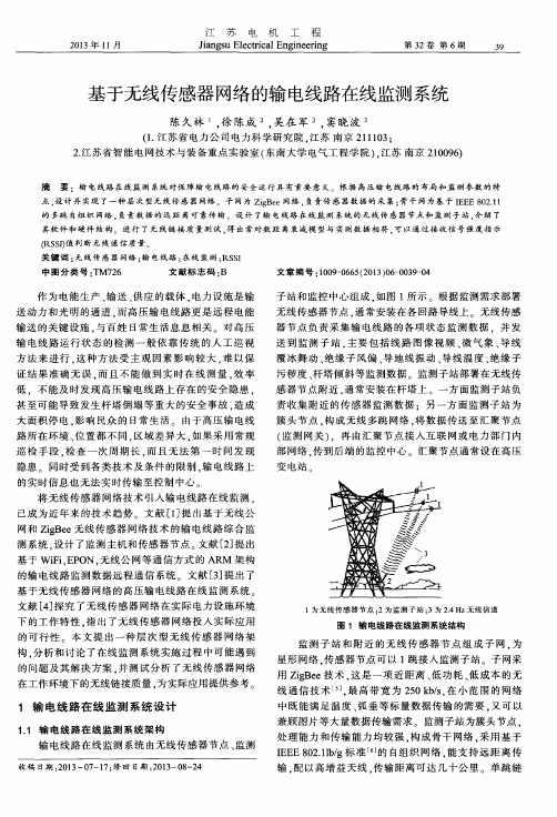
子站 和监 控 中心组 成 . 如图 1 所 示 。根据监测 需求 部署
无 线 传感器 节点 , 通 常安装 在各 回路 导线上 。无线 传感
器节 点 负责 采 集输 电线路 的各 项 状态 监 测 数据 .并 发 送 到监 测 子 站 。 主要 包 括 线 路 图像 视频 、 微气象 、 导 线
江
2 0 1 3 年 1 1 月
苏
电
机
工
程
第3 2卷 第 6 期 3 9
J i a n g s u E l e c t r i c a l E n g i n e e r i n g
基于无线传感器 网络的输 电线路在线监测系统
陈久 林 , 徐 陈成 , 吴在 军 , 窦晓 波
点. 设 计 并 实现 了一 种层 次 型 无 线传 感 器 网络 。 子 网为 z i g B e e网络 , 负责传 感 器数 据 的 采 集 : 骨 干 网为 基 于 I E E E 8 0 2 . 1 1
的 多跳 自组 织 网络 . 负责 数 据 的 远 距 离可 靠 传 输 。设 计 了输 电 线路 在 线监 测 系统 的 无 线传 感 器 节 点 和监 测子 站 , 介绍 了 其软 件 和硬 件 结构 进 行 了无 线 链接 质 量 测 试 . 得 出 常 对数 距 离衰 减模 型 与 实测 数 据 相 符 . 可 以通 过 接 收 信 号 强度 指 示
变 电站
证结 果 准 确 无误 . 而且 不能 做 到 实 时在 线 测 量 , 效率
低 .不 能 及 时发 现高 压输 电线路 上存 在 的安 全 隐患 . 甚至 可能 导致 发 生杆 塔倒 塌 等重 大 的安 全事 故 . 造成
大面 积停 电 . 影 响 民众 的 日常生 活 。 由于高 压输 电线
基于 RFID 和 ZigBee 的接地线在线监测系统设计

基于 RFID 和 ZigBee 的接地线在线监测系统设计孔英会;傅向苑;陈智雄;李春晓【期刊名称】《电测与仪表》【年(卷),期】2015(000)016【摘要】针对现有接地线缺乏自动化管理的现状,设计了一种基于RFID和ZigBee技术的临时接地线在线监测系统。
系统中采用基于ISO 14443 A标准的RC522读卡芯片实现接地线状态信息的可靠采集,通过基于IEEE 802.15.4标准的CC2530芯片实现信息的准确传输。
文章实现了系统硬件电路和软件架构设计,并进行了全面测试,针对变电站环境中的电磁干扰、障碍遮挡和网络拥塞等问题,提出了增加路由节点、调整发信间隔等通信可靠性改进方案。
该系统可以实现对变电站作业现场临时接地线挂接状态的在线实时监测,可靠性高,效果良好,有较高的推广价值。
【总页数】5页(P1-5)【作者】孔英会;傅向苑;陈智雄;李春晓【作者单位】华北电力大学电子与通信工程系,河北保定071003;华北电力大学电子与通信工程系,河北保定071003;华北电力大学电子与通信工程系,河北保定071003;华北电力大学电子与通信工程系,河北保定071003; 衡水供电公司,河北衡水053000【正文语种】中文【中图分类】TM862;TP277【相关文献】1.基于混合RFID技术的变电站临时接地线全过程管理系统设计 [J], 陈樑;盛志波;付军;郑原;朱彦升;2.基于ZigBee技术的输电杆塔倾斜在线监测系统设计 [J], 黄秀超;钟建伟;张建业;黄谋甫;田家俊;朱涧枫3.基于ZigBee和CAN总线的高压开关柜温度在线监测预警系统设计 [J], 陈凯彬; 耿新; 郭营生; 张宁; 陈森4.基于ZigBee网络的盾构滚刀磨损在线监测系统设计 [J], 肖静;刘琦;陈锐;廖志良5.基于接地线电流法的多线路电缆绝缘在线监测系统设计 [J], 郭大江;陈泉林因版权原因,仅展示原文概要,查看原文内容请购买。
zigbee无线传感器网络英文文献
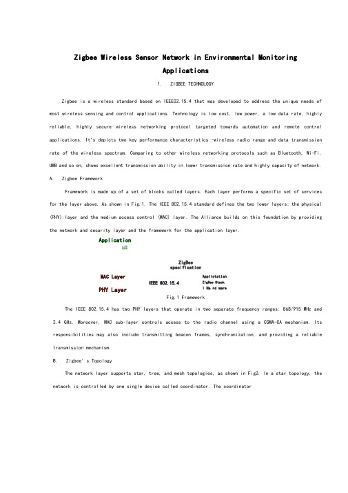
zigbee无线传感器网络英文文献兰州交通大学毕业设计(英文文献)Zigbee Wireless Sensor Network in Environmental MonitoringApplicationsI. ZIGBEE TECHNOLOGYZigbee is a wireless standard based on IEEE802.15.4 that was developed to address theunique needs of most wireless sensing and control applications. Technology is low cost, low power, a low data rate, highly reliable, highly secure wireless networking protocol targeted towards automation and remote control applications. It’s depicts two keyperformance characteristics – wireless radio range and data transmission rate of the wireless spectrum. Comparing to other wireless networking protocols such as Bluetooth, Wi-Fi, UWB and so on, shows excellent transmission ability in lower transmission rate and highly capacity of network.A. Zigbee FrameworkFramework is made up of a set of blocks called layers. Each layer performs a specificset of services for the layer above. As shown in Fig.1. The IEEE 802.15.4 standard definesthe two lower layers: the physical (PHY) layer and the medium access control (MAC) layer. The Alliance builds on this foundation by providingthe network and security layer and the framework for the application layer.Fig.1 FrameworkThe IEEE 802.15.4 has two PHY layers that operate in two separate frequency ranges: 868/915 MHz and 2.4GHz. Moreover, MAC sub-layer controls access to the radio channel using a CSMA-CA mechanism. Its responsibilities may also include transmitting beacon frames, synchronization, and providing a reliable transmission mechanism. B. Zigbee’s TopologyThe network layer supports star, tree, and mesh topologies, as shown in Fig.2. In a startopology, the network is controlled by one single device called coordinator. The coordinator1兰州交通大学毕业设计(英文文献)is responsible for initiating and maintaining the devices on the network. All other devices, known as end devices, directly communicate with the coordinator. In mesh and tree topologies, the coordinator is responsible for starting the network and for choosing certain key network parameters, but the network may be extended through the use ofrouters. In tree networks, routers move data and control messagesthrough the network using a hierarchical routing strategy. Mesh networks allow full peer-to-peer communication.Fig.2 Mesh topologiesFig.3 is a network model, it shows that supports both single-hopstar topology constructed with one coordinator in the center and the end devices, and mesh topology. In the network, the intelligent nodes are composed by Full Function Device (FFD) and Reduced Function Device (RFD). Only the FFN defines the full functionality and can become a network coordinator. Coordinator manages the network, it is to say that coordinator can start a network and allow other devices to join or leave it. Moreover, it can provide binding and address-table services, andsave messages until they can be delivered.Fig.3 Zigbee network model2兰州交通大学毕业设计(英文文献)II. THE GREENHOUSE ENVIRONMENTAL MONITORINGSYSTEM DESIGNTraditional agriculture only use machinery and equipment which isolating and no communicating ability. And farmers have to monitor crops’ growth by themselves. Even ifsome people use electrical devices, but most of them were restricted to simple communication between control computer and end devices like sensors instead of wire connection, which couldn’t be strictly defined as wireless sensor network. Therefore, bythrough using sensor networks and, agriculture could become more automation, more networking and smarter.In this project, we should deploy five kinds of sensors in the greenhouse basement. By through these deployed sensors, the parameters such as temperature in the greenhouse, soil temperature, dew point, humidity and light intensity can be detected real time. It is key to collect different parameters from all kinds of sensors. And in the greenhouse, monitoring the vegetables growing conditions is the top issue. Therefore, longer battery life and lower data rate and less complexity are very important. From the introduction about above, we know that meet the requirements for reliability, security, low costs and low power.A. System OverviewThe overview of Greenhouse environmental monitoring system, which is made up by one sink node (coordinator), many sensor nodes, workstation and database. Mote node and sensor node together composed of each collecting node. When sensors collect parameters real time, such as temperature in the greenhouse, soil temperature, dew point, humidity and light intensity, these data will be offered to A/D converter, then by through quantizing and encoding become the digital signal that is able to transmit by wireless sensor communicating node. Each wireless sensor communicating node has ability of transmitting, receiving function.In this WSN, sensor nodes deployed in the greenhouse, which can collect real time data and transmit data to sink node (Coordinator) by the way of multi-hop. Sink node complete the task of data analysis and data storage. Meanwhile, sink node is connected with GPRS/CDMA can provide remote control and data download service. In the monitoring and controlling room, by running greenhouse management software, the sink node can periodically receives the data from the wireless sensor nodes and displays them on monitors.3兰州交通大学毕业设计(英文文献)B. Node Hardware DesignSensor nodes are the basic units of WSN. The hardware platform is made up sensor nodes closely related to the specific application requirements. Therefore, the most important work is the nodes design which can perfect implement the function of detecting and transmissionas a WSN node, and perform its technology characteristics. Fig.4 shows the universal structure of the WSN nodes. Power module provides the necessary energy for the sensor nodes. Data collection module is used to receive and convert signals of sensors. Data processing and control module’s functions are node device control, task scheduling, and energy computing and so on. Communication module is used to senddata between nodes and frequency chosen and so on.Fig.4 Universal structure of the wsn nodesIn the data transfer unit, the module is embedded to match the MAC layer and the NET layer of the protocol. We choose CC2430 as the protocol chips, which integrated the CPU,RF transceiver, net protocol and the RAM together. CC2430 uses an 8 bit MCU (8051), andhas 128KB programmable flash memory and 8KB RAM. It also includesA/D converter, some Timers, AES128 Coprocessor, Watchdog Timer, 32K crystal Sleep mode Timer, Poweron Reset, Brown out Detection and 21 I/Os. Based on the chips, many modules for theprotocol are provided. And the transfer unit could be easily designed based on the modules.As an example of a sensor end device integrated temperature, humidity and light, the design is shown in Fig. 5.4兰州交通大学毕业设计(英文文献)Fig.5 The hardware design of a sensor nodeThe SHT11 is a single chip relative humidity and temperature multi sensor module comprising a calibrated digital output. It can test the soil temperature and humidity. The DS18B20 is a digital temperature sensor, which has 3 pins and data pin can link MSP430directly. It can detect temperature in greenhouse. The TCS320 is a digital light sensor.SHT11, DS18B20 and TCS320 are both digital sensors with small size and low powerconsumption. Other sensor nodes can be obtained by changing the sensors.The sensor nodes are powered from onboard batteries and the coordinator also allows to be powered from an external power supply determined by a jumper.C. Node Software DesignThe application system consists of a coordinator and several end devices. The general structure of the code in each is the same, with an initialization followed by a main loop.The software flow of coordinator, upon the coordinator being started, the first action of the application is the initialization of the hardware, liquid crystal, stack and application variables and openingthe interrupt. Then a network will be formatted. If this net has been formatted successfully, some network information, such as physical address, net ID, channel number will be shown on the LCD. Then program will step into application layer and monitor signal. If there is end device or router want to join in this net, LCD will shown this information, and show the physical address of applying node, and the coordinator will allocate a net address to this node. If the node has been joined in this network, the data transmitted by this node will be received by coordinator and shown in the LCD.The software flow of a sensor node, as each sensor node is switched on, it scans all5兰州交通大学毕业设计(英文文献)channels and, after seeing any beacons, checks that the coordinatoris the one that it is looking for. It then performs a synchronizationand association. Once association is complete, the sensor node enters a regular loop of reading its sensors and putting out a frame containing the sensor data. If sending successfully, end device will step into idle state; by contrast, it will collect data once again and send to coordinator until sending successfully.D. Greenhouse Monitoring Software DesignWe use VB language to build an interface for the test and this greenhouse sensor network software can be installed and launched on any Windows-based operating system. It has 4dialog box selections: setting controlling conditions, setting Timer, setting relevant parameters and showing current status. By setting some parameters, it can perform the functions of communicating with port,data collection and data viewing.6兰州交通大学毕业设计(英文文献)无线传感器网络在环境监测中的应用Zigbee技术I. Zigbee是一种基于802.15.4的无线标准上被开发用来满足大多数无线传感ZigbeeIEEE和控制应用的独特需求。
电子信息及自动化 外文翻译 外文文献 英文文献 基于ZigBee无线传感器网络的矿工的位置探测研究

基于ZigBee无线传感器网络的矿工的位置探测研究张秀萍, 韩广杰, 朱昌平, 窦燕, 陶剑锋河海大学计算机与信息工程学院中国常州E-mail:zhangxiup@ Zhucp315@摘要:随着计算机的飞速发展,通信和网络技术,特别是无线传感器和嵌入式技术的应用,使得无线传感器网络(WSNs)技术在产业领域和我们的日常生活得到了广泛关注。
基于ARM7TDMI-S CPU和ZigBee 的WSNs在提速和优化网络移动节点的应用,丰富的信息采集中,以及在通信中实时时间的协调均有可取之处,具有低功耗连续作业特点,因此它是非常适合用于确定矿工在地下的位置。
本文提出和分划WSN的网络计划及信息处理与通信技术,重点专注于实时协作。
通过传感器准确获得矿工的移动信息。
之后的位置信息传送可靠的监控中心。
不断变化的运行测试结果表明没有信息丢失或者没有未被采集到的信息。
因此,这个计划是稳定和有效的,将在煤矿安全中发挥积极作用,在我看来这正是Zigbee 无线传感器网络的正确特点。
关键词:ZigBee的ARM7TDMI-S内核; CC2420的; 无线传感器网络;矿工位置确定一、简介无线传感器网络(WSNs)是规模大,无线自组织网络。
它是整合计算机通信,网络技术,嵌入式MCU和无线传感器技术,具有感知和沟通能力。
【1】节点有低低成本,小尺寸特点。
其中大部分可以工作区域传播,收集数据,并进行处理数据和通信。
无线传感器节点通常工作在无线电频率(RF)频段。
节点构成一个分层架构现场监测数据的网络。
它通常适用在工业,农业,远程医疗和环境监测。
我们都知道,煤炭生产中的威胁复杂的工作条件,如有毒气体,透水,塌陷,顶板等。
【2】一旦发生事故发生时,它会危及矿工的生命。
因此它是地面人员的当务之急,要明确矿工的确切位置,以便为及时采取措施。
因此为矿工成立一个无线传感器网络监控矿井有很大的应用价值。
二、方案优选矿工的位置监测系统主要技术规范要求归纳如下:(1)定位精度为10米。
基于Zigbee(CC2530)的温湿度上位机监测系统设计——毕业设计

基于ZigBee技术的温湿度远程监测系统设计学生:陈园(指导老师:吴琰)(淮南师范学院电子工程学院)摘要: 针对目前温室大棚农作物大面积种植,迫切需要科学的方法进行智能远程监测的研究现状,设计出一套温湿度远程监测系统。
该系统是有多个采集终端和一个协调控制器组成。
多个终端分别放置不同的大棚内进行实时采集数据,协调控制器的作用就是将多个采集终端通过无线传输过来的的数据进行分析并和PC机连接。
PC机上运行上位机软件实时的监测各大棚的温湿度信息。
多个终端和协调控制器均采用TI公司新一代CC2530芯片;温湿度传感器采用市场上比较流行的DHT11;无线传输采用ZigBee协议;上位机软件采用labVIEW编写,并通过RS-232与协调控制器连接通信。
通过实物测试了ZigBee无线传输的稳定可靠性,丢包率在误差范围内。
温湿度采集有0.5s延时时间,满足实时性要求。
关键词:终端;协调控制器;DHT11;CC2530;ZigBee;上位机Design of Remote Monitoring System for Temperature andHumidity based on ZigBee TechnologyStudent: Chen Yuan(Faculty Adviser:Wu Yan)(college of electronic engineering, Huainan Normal University)Abstract:According to the current situation of the research on the intelligent remote monitoring of greenhouse crops, the research status of intelligent remotemonitoring is urgently needed, and a set of remote monitoring system fortemperature and humidity is designed. The system is composed of a plurality ofacquisition terminals and a coordinated controller. Multiple terminals are placed indifferent greenhouses for real-time collection of data, the role of the coordinationcontroller is to collect more than one collection terminal through wireless datatransmission over the data analysis and PC machine connection. Temperature andhumidity information operation software of PC real-time monitoring of thegreenhouse on PC. A plurality of terminals and a coordinated controller are used ina new generation of CC2530 chip of TI company; temperature and humidity sensorused on the market more popular DHT11; wireless transmission based on ZigBeeprotocol; PC software using LabVIEW, and connected with the communicationthrough the RS-232 and coordination controller. The reliability of ZigBee wirelesstransmission stability test through the physical, the packet loss rate is in the rangeof error. Temperature and humidity acquisition 0.5s time delay, meet the real-timerequirements.Keywords:Terminal; coordination controller; DHT11;CC2530; ZigBee; host computer1. 绪论1.1 设计背景和研究意义现如今我国已经成为世界第一粮食生产大国,据有关统计说明,我国农作物设施栽培面积已经超过210万hm2。
基于ZigBee技术的双核远程实时电力监测系统设计

电力系统54丨电力系统装备 2019.2Electric System2019年第2期2019 No.2电力系统装备Electric Power System Equipment随着电力系统的快速发展,电网容量扩大,使其结构更为复杂,使得电力系统的稳定性问题日益突出,社会对电网可靠性、安全性、高效性的要求日益提高,迫切需要双向智能的电网[1]。
电力系统中的各项参数,包括电流、电压、有功和无功功率、频率、温度等,是电力系统安全运行和电网电能质量的重要参数指标[2-4]。
电力系统安全稳定的运行不仅保障了各类用户生产生活安全,还可以延长设备使用寿命,确保生产加工产品质量。
现有的电力监测系统大多采用有线数据采集及传输,布线容易杂乱,调动设备困难,且无法实时有效地对电网进行监控,对于电力系统的监测还有待完善[5]。
常规的利用无线公用网络可以充分利用现有资源,但数据传送速率有限,还存在付费运行以及网络管理的问题[6]。
针对上述实际情况,研究开发一种综合、智能、高效的电力远程监测体系意义重大。
1 无线远程监测系统整体设计由于电网监测系统的特殊性,对监测设备的传输数据通[摘 要]为了更有效地实时监测电网的各项电力参数,需提高电网数据参数高效综合的通信,使电力系统在不断自我监测和自我纠错中保持高质量、高可靠性的电力传输。
无限远程监测系统综合运用ZigBee 无线通信技术,可分析部署在各区域的多个采样点的数据,提高采样精度,并将监测数据汇集到监测中心进行数据分析。
实验和现场测试表明,该系统性能稳定,可对智能电网的运行提供可靠、准确、实时的数据保障。
[关键词]ZigBee ;单片机;智能电网 ;交流采样[中图分类号]TM752 [文献标志码]A [文章编号]1001–523X (2019)02–0034–02Design of Dual-core Remote Real-time Power MonitoringSystem Based on ZigBee TechnologySun Yi-wen ,Ye Jing[Abstract ]In order to monitor the power parameters more effectively in real time, improve the efficient and comprehensive communication of the data parameters of the power grid, and maintain high quality and reliability of power transmission in the continuous self-monitoring and self-correcting of the power system. The system integrates ZigBee wireless communication technology, which can analyze the data of multiple sampling points deployed in various regions, improve the sampling accuracy, and collect the monitoring data to the monitoring center for data analysis. Experiments and field tests show that the system has stable performance and improves reliable, accurate and real-time data guarantee for the operation of smart grid.[Keywords ]zigBee; single chip microcomputer; smart grid; AC sampling 基于ZigBee技术的双核远程实时电力监测系统设计孙毅文,叶 静(南京航空航天大学自动化学院,江苏南京 211106)破限制,积极推进电力自动化技术在电力工程中的运用,不断挖掘到更有价值的发展前景。
Zigbee无线传感器网络英文文献
Zigbee Wireless Sensor Network in Environmental MonitoringApplications1. ZIGBEE TECHNOLOGYZigbee is a wireless standard based on IEEE02.15.4 that was developed to address the unique needs of most wireless sensing and control applications. Technology is low cost, low power, a low data rate, highly reliable, highly secure wireless networking protocol targeted towards automation and remote control applications. It's depicts two key performance characteristics -wireless radio range and data transmission rate of the wireless spectrum. Comparing to other wireless networking protocols such as Bluetooth, Wi-Fi, UWB and so on, shows excellent transmission ability in lower transmission rate and highly capacity of network.A. Zigbee FrameworkFramework is made up of a set of blocks called layers. Each layer performs a specific set of services for the layer above. As shown in Fig.1. The IEEE 802.15.4 standard defines the two lower layers: the physical (PHY) layer and the medium access control (MAC) layer. The Alliance builds on this foundation by providing the network and security layer and the framework for the application layer.Application口导ZigBeespecificationFig.1 FrameworkThe IEEE 802.15.4 has two PHY layers that operate in two separate frequency ranges: 868/915 MHz and2.4 GHz. Moreover, MAC sub-layer controls access to the radio channel using a CSMA-CA mechanism. Its responsibilities may also include transmitting beacon frames, synchronization, and providing a reliable transmission mechanism.B. Zigbee' s TopologyThe network layer supports star, tree, and mesh topologies, as shown in Fig2. In a star topology, the network is controlled by one single device called coordinator. The coordinatorMAC LayerIEEE 802.15.4PHY Layer Applictatian ZlgSee Stack I Ha rd wareis responsible for initiating and maintaining the devices on the network. All other devices, known as end devices, directly communicate with the coordinator. In mesh and tree topologies, the coordinator is responsible for starting the network and for choosing certainkey network parameters, but the network may be extended through the use of routers. In tree networks, routers move data and control messages through the network using a hierarchicalrouting strategy. Mesh networks allow full peer-to-peer communication.• Coordinator • Router (FFD| Fig.2 Mesh topologiesFig.3 is a network model, it shows that supports both single-hop star topology constructed with one coordinator in the center and the end devices, and mesh topology. In the network, the intelligent nodes are composed by Full Function Device (FFD) and Reduced Function Device (RFD). Only the FFN defines the full functionality and can become a network coordinator. Coordinator manages the network, it is to say thatcoordinator can start a network and allow other devices to join or leave it. Moreover, it can provide binding andaddress-table services, and save messages until they can be delivered.11. THE GREENHOUSE ENVIRONMENTAL MONITORINGSYSTEM DESIGNTraditional agriculture only use machinery and equipment which isolating and no communicating ability. And farmers have to monitor crops growth by th emselves. Even if some people use electrical devices, but most of them were restricted to simple communication between control computer and end devices like sensors instead X Star NetworkEnd Device i|RF 口)Mesh Network(Best RellabihtylTree Network (Least RAM) Z\n = H Coord in atariFFD.LlnHEnd 口・*lx|甘FEI nr< A »1)rFig.3 Zigbee network modelof wire connection, which couldn ' be strictly defined as wireless sensor network. Therefore, by through using sensor networks and, agriculture could become more automation, more networking and smarter.In this project, we should deploy five kinds of sensors in the greenhouse basement. By through these deployed sensors, the parameters such as temperature in the greenhouse, soil temperature, dew point, humidity and light intensity can be detected real time. It is key to collect different parameters from all kinds of sensors. And in the greenhouse, monitoring the vegetables growing conditions is the top issue. Therefore, longer battery life and lower data rate and less complexity are very important. From the introduction about above, we know that meet the requirements for reliability, security, low costs and low power.A.System OverviewThe overview of Greenhouseenvironmental monitoring system, which is made up by one sink node (coordinator), many sensor nodes, workstation and database. Mote node and sensor node together composed of each collecting node. When sensorscollect parameters real time, such as temperature in the greenhouse, soil temperature, dew point, humidity and light intensity, these data will be offered to A/D converter, then by through quantizing and encoding become the digital signal that is able to transmit by wireless sensor communicating node. Each wireless sensor communicating node has ability of transmitting, receiving function.In this WSN, sensor nodes deployed in the greenhouse, which can collect real time data and transmit data to sink node (Coordinator) by the way of multi-hop. Sink node complete the task of data analysis and data storage. Meanwhile, sink node is connected with GPRS/CDMA can provide remote control and data download service. In the monitoring and controlling room, by running greenhouse management software, the sink node can periodically receives the data from the wireless sensor nodes and displays them on monitors.B.Node Hardware DesignSensor nodes are the basic units of WSN. The hardware platform is made up sensor nodes closely related to the specific application requirements. Therefore, the most important work is the nodes design which can perfect implement the function of detecting and transmission as a WSN node, and perform its technology characteristics. Fig.4 shows the universal structure of the WSN nodes. Power module provides the necessary energy for the sensor nodes. Data collection module is used to receive and convert signals of sensors. Data processing and control module' sanctions are node device control, task scheduling, and energy computing and so on. Communication module is used to send data between nodes and frequency chosen and so on.Fig.4 Universal structure of the wsn nodesIn the data transfer unit, the module is embedded to match the MAC layer and the NET layer of the protocol. We choose CC 2430 as the protocol chips, which integrated the CPU, RF transceiver, net protocol and the RAM together. CC2430 uses an8 bit MCU ( 8051), and has 128KB programmable flash memory and 8KB RAM. It also includes A/D converter, some Timers, AES128 Coprocessor, Watchdog Timer,32K crystal Sleep mode Timer, Power on Reset, Brown out Detection and 21 I/Os. Based on the chips, many modules for the protocol are provided. And the transfer unit could be easily designed based on the modules.As an example of a sensor end device integrated temperature, humidity and light, the design is shown in Fig.5.Fig.5 The hardware design of a sensor nodeThe SHT11 is a single chip relative humidity and temperature multi sensor module comprising a calibrated digital output. It can test the soil temperature and humidity. The DS18B20 is a digital temperature sensor, which has 3 pins and data pin can link MSP 430 directly. It can detect temperature in greenhouse. The TCS320 is a digital light sensor. SHT11, DS18B20 and TCS320 are both digital sensors with small size and low power consumption. Other sensor nodes can be obtained by changing the sensors.The sensor nodes are powered from onboard batteries and the coordinator also allows to be powered from an external power supply determined by a jumper.C.Node Software DesignThe application system consists of a coordinator and several end devices. The general structure of the code in each is the same, with an initialization followed by a main loop.The software flow of coordinator, upon the coordinator being started, the first action of theapplication is the initialization of the hardware, liquid crystal, stack and application variables and opening the interrupt. Then a network will be formatted. If this net has been formatted successfully, some network information, such as physical address, net ID, channel number will be shown on the LCD. Then program will step into application layer and monitor signal. If there is end device or router want to join in this net, LCD will shown this information, and show the physical address of applying node, and the coordinatorwill allocate a net addressto this node. If the node has been joined in this network, the data transmitted by this node will be received by coordinator and shown in the LCD.The software flow of a sensor node, as each sensor node is switched on, it scans all channels and,after seeing any beacons, checks that the coordinator is the one that it is looking for. It then performs a synchronization and association. Once association is complete, the sensor node enters a regular loop of reading its sensors and putting out a frame containing the sensor data. If sending successfully, end device will step into idle state; by contrast, it will collect data once again and send to coordinator until sending successfully.D.Greenhouse Monitoring Software DesignWe use VB language to build an interface for the test and this greenhouse sensor network software can be installed and launched on any Windows-based operating system. It has 4 dialog box selections: setting controlling conditions, setting Timer, setting relevant parameters and showing current status. By setting some parameters, it can perform the functions of communicating with port, data collection and data viewing.Zigbee无线传感器网络在环境监测中的应用I. Zigbee技术Zigbee是一种基于IEEE802.15.4的无线标准上被开发用来满足大多数无线传感和控制应用的独特需求。
基于zigbee的变电站无线温度监测系统

基于zigbee的变电站无线温度监测系统关键词:zigbee 无线测温智能电网变电站引言:基于zigbee的无线温度监测系统是利用微型温度传感器、zigbee无线组网通信技术和现代信息处理技术实现对电力电缆、高压开关柜、输配电线路、变电站高压母线接头等待测点的温度实时在线监测。
系统具有低功耗、数据无线传输、精度高、响应速度快、操作灵活、组网方便等优势。
一、应用需求输配电电缆接头、电力设备的导电母线接头、高压开关柜触头、刀闸开关、干式变压器、箱式变电站等设备,在长期运行过程中母线承接电流过大或开关接触电阻过大时,极易引起温升过高,而这些发热部位的温度无法监测,由此最终导致火灾事故。
如得不到及时解决将使绝缘部件性能降低,甚至导致击穿,造成恶性事故,从而造成重大经济损失。
及时测量高压母线接头和高压开关触点温度,为采取有限措施提供准确信息,将是电力系统安全运行的重要保障。
应用范围:1),电力电缆可实时监测电缆接头的温度、电缆本身温度、电缆分支箱内接头开关等设备的温度2),高压开关柜可实时监测高压开关柜内开关触点、母线接头、电缆接头等设备的温度3),输配电线路、变压器输配电线路的温度、变压器及其连接件设备的温度4),变压站高压母线接头温度在线监测及过热预警二,工作原理无线温度传感器直接安装在电缆、电缆接头、电容器外壳等可能发热处。
每个传感器都具有唯一ID,实际安装时要记录监测点物理位置,并一起录入主机数据库中。
传感器定时启动测量并发送监测点温度数据。
当监测点温度超过预设值时立即报警并提高工作频率。
这些温度数据通过2.4GHz无线信道传输到中心基站。
中心基站通过RS-485(CAN、以太网)总线或者GPRS将温度数据上传给主机,并响应主机的各种命令。
主机将总线温度数据进行处理并保存,用图形化的界面实时显示各监测点的温度,通过分析监测点温度变化趋势、比较设备与环境的相对温升,分析可能过热或急剧升温的情况,提前发出预警信号,提醒管理人员进行处理。
- 1、下载文档前请自行甄别文档内容的完整性,平台不提供额外的编辑、内容补充、找答案等附加服务。
- 2、"仅部分预览"的文档,不可在线预览部分如存在完整性等问题,可反馈申请退款(可完整预览的文档不适用该条件!)。
- 3、如文档侵犯您的权益,请联系客服反馈,我们会尽快为您处理(人工客服工作时间:9:00-18:30)。
Study on Monitoring System of On-Line Power Transmission Lines Based on ZigBee Technology*ZHONG Yun-ping1, CHENG Xiao-hua1, DAI Dong1, ZHANG Jian-wei2, ZHAI Shao-lei2(1.South China University of Technology, Guangzhou 510640,China.2. Electric Power Research Institute of Yunnan Electric Power Test & ResearchInstitute Group Corporation Limited, Kunming 650217, China)Received July 2012; accepted November 2012 Abstract:Combining the need of monitoring high voltage in powersystem with the technical advantages of ZigBee,this paperproposes a set of high -voltage wireless monitoring system withthe characteristics of ZigBee wireless sensor networks, thebasic principles and its composition, and it presents the useof the emerging ZigBee wireless networking technology in theon-line monitoring system. ZigBee communication module, theinducing power design on high -voltage transmission lines, solarmodule design, and the structure design of software system arealso described in detail. The system has advantages of highreliability, simple arrangement, good expandability, lowrunning cost. The laboratory test results are stable andreliable.Key words:ZigBee technology, wireless communication technology,transmission line monitoring, CC2530, wireless sensor network* Fund project: the project is supported by the national 863 plan (2011 aa05a120)1. IntroductionIn recent years, with the development of social economy, the national power consumption has skyrocketed, ultra-high voltage power grid construction and scale expands rapidly. Because of the high voltage transmission line has a long distance, wide distribution, patrol and maintenance difficulty etc[1]. In remote areas, the terrain complex work in harsh environment network of transmission lines of transmission line and its environment, meteorological parameters, the real-time remote monitoring become an urgent work, based on the transmission line running status real-time monitoring, establish corresponding natural disaster warning mechanism, can reduce the power outage caused economic losses, improve the stability of the safety of power grid operation efficiency[2]. Therefore, to establish the stable operation of the transmission line on-line monitoring system for power grid plays an important role, and the establishment of a transmission line on-line monitoring system is an important part of the smart grid[3].Traditional monitoring network is given priority to with cable, wiring complexity, low reliability, safety, high cost, low extension and maintenance difficulties and other issues. The common wireless communication technology, such as GPRS, Wi-Fi, that exist such problems as high cost, large power consumption. Designed a kind of wireless sensornetwork based on ZigBee technology, it has low power consumption, low cost, safe, reliable and network advantages of large capacity and high efficiency of the collection. At the same time because of it’s no wiring, easy extension, high flexibility, etc. it has been applied gradually in the transmission line monitoring system [4]. Transmission distance of each network node can from the standard 80 meters, after add power amplifier can be extended to a few hundred meters, even several kilometers; In addition the ZigBee network can also communicate with other existing communication network..Considering the high voltage transmission line monitoring equipment working environment and conditions, this paper designs a wireless transmission line on-line monitoring system based on ZigBee technology, combining induction way to fundamentally solve the problem of the high voltage insulation, has a large capacity of the network at the same time, small volume, light weight, low power consumption, and the advantages of convenient installation, is an ideal solution for high voltage transmission line monitoring.2. The overall frame structure of the systemWireless Sensor networks is composed of a large number of micro Sensor nodes deployed in monitoring area, through Wireless communication mode to form a multiple hops self-organizing network system, collaborativeperception, and collection and processing network coverage area by monitoring object information, and sent to the coordinator. Sensors, monitoring objects, and the coordinator constitute the three elements of the wireless sensor network.Wireless sensor network monitoring system based on ZigBee technology structure [5] is shown in figure 1.GPRSReceiverFig.1 Monitoring system’s structure of wireless sensor networkSensor network system includes sensor nodes (sensor node), routing node, the coordinator node and monitoring host. Within the scope of sensornodes deployed in monitoring area, can constitute a sensor network by way of self-organization. Sensor nodes monitoring data can be transmitted along the other sensor nodes, jumping by, monitoring data in the process of transmission is likely to be more than one node processing, through multiple hops posterior to the coordinator node. Wireless sensor monitoring system consists of sensors, wireless router nodes, the coordinator node, the data collection center, monitoring host, sensor acquisition node is installed on the high voltage transmission line and tower, can be used for the collection, transmission line conductor temperature tension, lightning current data, through the wireless network, such as temperature, tension, lightning current data through wireless router nodes is passed to the coordinator, the coordinator of the RS232 serial port to monitor host, monitoring host through the GPRS data transmission to the background.3. The design of system hardware3.1 based on CC2530 ZigBee module designSensor nodes, wireless routing node, the coordinator node adopt CC2530 chip of TI Company newly, CC2530 is based on a 2.4 GHz IEEE 802.15.4 on a real piece of ZigBee (SoC) solution. It can build strong at very low cost network nodes. CC2530 combines the leading the good performance of RF transceiver, the industry standard of enhanced 8051 CPU, the systemprogrammable flash memory, 8 KB of RAM and many other powerful features CC2530 with different operation mode, makes it especially adapted to ultra low power requirements of the system. Sensor is responsible for the monitoring area information acquisition and data transfer; Processor module is responsible for the control of the operation of sensor nodes, data storage and processing itself and data from other nodes; Wireless communication module is responsible for the wireless communication with other sensor nodes, exchange control information and to send and receive data; Running mode conversion between short time further ensures that the low energy consumption; Power supply module for sensor nodes provide the energy needed to run.In this system, according to the different functions in the network, the wireless modules can be divided into wireless sensor module (that is, the terminal nodes of the sensor data acquisition and communication module) and the coordinator module, as shown in figure 2.Fig.2 Block diagram of monitoring deviceWireless sensor nodes usually consist of four main modules: sensor (signal adjusting, transmitter), a processor module (microprocessors, memory), a wireless transceiver module, wireless network, MAC, transceiver) and a power supply module, power supply, AC-DC). Sensor module and data acquisition node (CC2530) communication using RS-485, when send sensors read data acquisition node command, if the sensor received reply read data command, the corresponding data as a response, read sensor serial data acquisition node, and the serial port read packets package check generates a message, send packets processed task, the final data to the frequency of 2.4 GHz is sent to the coordinator (or router nodes).Coordinator module and terminal node module is different is thecoordinator with the wireless sensor in the form of wireless data communication, and each terminal node receives data via a serial port RS-232 transmission to the ARM9 data collection platform.3.2 The power supply designAt present, the electronic devices at high pressure side can take way mainly include solar battery and battery laser power and electronic current induction can (i.e., induction can). Considering the high voltage power electronic device on the transmission line maintenance and working environment, etc factors, unfavorable use battery and solar battery power supply. As a result, the design of the power system is divided into two kinds of situations: the first kind of circumstance, has greater advantages for monitoring equipment on the transmission line, adopt induction way to sensor and ZigBee module power supply. Sensor module voltage grade for DC12V, ZigBee module power supply voltage is DC2.5 ~ 3.6 V, so the induction can should have two different way, and the output voltage; The second case, the tower for the monitoring equipment includes monitoring host, use of solar battery power supply.According to the law of electromagnetic induction, When alternating current flows through the set of high voltage side of the ring core bus (the equivalent of a winding), on the annular core coil (secondary winding) induction of induction electromotive force, called high voltage induction. Voltage induction power supply guarantee for high voltage side ofelectronic equipment and reliable power at the same time, and can ensure the reliability of the insulation. The change of the high voltage side bus current situation is very complicated, when resources used current minimum may be only A few A, and when happen transmission line fault transient current may reach tens of kA[6].Considering the change of the transmission line current unpredictability, electronic device for transmission line power supply increased the compensation loop, two with different magnetic ring core material, which can take core using the initial permeability significantly higher than the initial compensation core permeability of soft magnetic materials, and can take reverse series winding andcompensation winding connection[7], as shown in figure 3.highvoltagebusFig.3 Device of inducing powerInduction power supply can by taking quad, compensating winding, impact protection unit, the whole bridge rectifier, regulator, filter unit drop of subsection pressure units. When the high voltage bus bar through the electric current is small, due to large initial magneticpermeability of the compensation winding, the compensation winding induced voltage is negligible, under the condition of high current can compensation winding induction electromotive force and winding induction electromotive force partially offset each other, to reduce the heat loss, so that can take the power supply in the high voltage bus a relatively wide range change can work normally. When impact current is too large, due to the limited compensation winding, to protect can take power from damage under impulse current, between the whole bridge rectifier and induction winding to join impact protection unit. When current flows through too much impact on a bus, impact protection unit, the winding current flow only impact protection unit and the protection of the whole bridge rectifier circuit level and after, during normal working condition impact protection unit does not work. By voltage filtering unit of after full bridge rectifier voltage ripple voltage regulator and filter out noise, make its have the pulsating multiplexed output dc small, little harmonic, safe and stable operation to ensure electronic devices [8].For tower on electronic device adopt solar battery power supply mode, selects the conversion efficiency of monocrystalline silicon solar panels, the standard for the power to choose: first to calculate the consumption of hours a day, when the output power for 1P (W), if every day use 1T (h),the power consumption for 11T PP ⋅=(Wh). Calculate the solar panels: according to the daily sunshine time is T hour’s calculation effectively,and the loss in the process of considering the charging efficiency and charging, the output power of solar panels should be )(η⋅=T P P O (W). Where η is the charging process, the actual use of power of solar panels? Battery with small volume, long life, good environmental compatibility, high temperature resistant, suitable for fast charging, high safety coefficient of lithium iron phosphate batteries, battery capacity calculation formula:C T N P A B O L C ⋅⋅⋅= (Ah)Type A is the safety factor;P for daily average power consumption, as the working current multiplied by the first day working hours;L N for the longest continuous rainy days; The O T for temperature correction coefficient; C for battery discharge depth.4. The design of system softwareSystem software design is divided into the coordinator routing node software design, software design and software design of wireless sensor nodes [9,10][10], in addition to the three required different functionality, its design method and process are the same. After the system is powered on, performing ZMain file. The c of the main () function realization of the hardware initialization, including customs always interrupt osal_int_disable, initialization of board hardware setup HAL_BOARD_INIT initialization (), I/O port InitBoard (), initialize the HAL layer driverHalDriverInit (), initialize the nonvolatile memory osal_nv_init (), initialize the MAC layer ZMacInit (), distribution, a 64-bit address zmain_ext_addr osal_init_system (), initialize the operating system (), etc.When the smooth completion of initialization, execution osal_start_system () function starts running OSAL (Operating system abstraction layer) Operating system. The task scheduling function polling each task is ready or not, according to the priority of the task event. If there is a high priority task ready call the tasksArr [] processing function corresponding to the task in place to handle events, until all ready tasks. If there is no ready task the task list, you can make the processor into sleep mode to achieve low power osal_start_system () once executed, is no longer return to the Main () function.OSAL is the core of the protocol Stack, Z - any a subsystem of the Stack as a task of OSAL and therefore in the development of the application layer, must through the creation of OSAL task to run the application, in osalInitTasks () function creates OSAL tasks, including TaskID unique identification number for each task. Any OSAL task must be divided into two steps: one is to task initialization; second is processing tasks event task initialization as shown in figure 4.Fig.4 Workflow of initializingIs the application run at the bottom of the ZigBee protocol stack, the application first carries on the system initialization process, function call osal_init system (), including hardware initialization and protocol stack initialization, hardware initialization including serial port initialization, the I/O initialization; Initialization protocol stack is mainly set protocol stack the layers of the initial state. ZigBee protocol stack by adopting the idea of OSAL operating system to build, rotary circulation mechanism, namely task events after the initialization of each layer, the system to enter low power mode, if any task, system will be awakened, and began to enter the interrupt handling events, after the treatment will continue to enter low power mode, if there are several events occur at the same time, the system will determine the priority among events, successive processing events, this kind of system architecture, can greatly reduce the power consumption of the system.Because of the limitation of wireless sensors work environment and conditions for wireless sensors initialized in electricity after operation, can automatically to the coordinator (or routing nodes) automatically for the net, according to the properties of self-organization network ZigBee agreement completed network registration, distribution of assigned tasks such as operation, the node flow chart shown in figure 5.Fig.5 Workflow of nodeEntered the stage of normal work, according to the actual need real-time sensor data, CC2530 according to the set time interval to thesensor through RS485 sends a request to read data command When CC2530 detected a serial port operation, according to the serial port operation taskID serial processing function calls a corresponding task events and sensor after receiving command corresponding to the detected information via RS485 to CC2530 response, CC2530 collected sensor data carries on the preliminary processing of backwardness to the coordinator node of ZigBee network coordinator reply received after a successful close sensor node power supply, system again into dormancy stage. According to the serial port operation taskID serial processing function calls a corresponding task events and sensor after receiving command corresponding to the detected information via RS485 to CC2530 response, CC2530 collected sensor data carries on the preliminary processing of backwardness to the coordinator node of ZigBee network coordinator reply received after a successful close sensor node power supply, system again into dormancy stage.5. Application examplesUse for inspection monitoring system, with wire tension sensor as an example to test in the laboratory, node CC2530 every 10 s send a read to pull sensor measurement information command, tension sensor strain data after a successful receipt, once every 50 s read voltage information. Using serial debugging assistants, according to the pull data and thepower supply voltage as shown in figure 6, the right to left to the corresponding hexadecimal display, 796 f for the coordinator for the 16-bit network address of the sensor distribution.Fig.6 Data displayed on UART assist6. ConclusionsIn this paper, based on the ZigBee wireless communication technology, developed a transmission line conductor tension wireless monitoring system. The system is composed of ZigBee nodes that measure the wire tension and transmission to the coordinator, and then the pull data will be sent to the monitoring host via RS232, which can effectively solve the problem of measuring the insulation of wire tension, formed a set of high reliability, lower cost, easy to install, easy to manage, close to the free maintenance solutions, easy to expand (such as it can easy to join wire temperature sensor , weather sensor, lightning current sensor nodeetc.),provides the powerful guarantee for the safe and reliable operation of power system.AcknowledgmentThe authors also gratefully acknowledge the helpful comments and suggestions of the reviewers, which have improved the presentation.REFERENCES[1] LIANG Ming, MA Helou, CHEN Haibin, etal. The development of the high voltage induction can take communication power supply [J]. Electric Power, 2010, 29(21): 34-35.[2] ZHOU Yao, WANG Wei, XU Lijie, etal. Transmission Line Temperature on-line Monitoring System Based on ZigBee [C]. International Conference on Sustainable Power Generation and Supply (SUPERGEN 2009) .[3] De Rybel, Tom Singh, Arvind Pak, Phalmoniroth Marti, Jose R.Self-powered on-line signal injection based on a current transformer Electric Power Conference, EPEC, 2008 IEEE Canada.[4] WANG Lingzhi, LI Chunmao, YUAN Lixing. A Temperature-Rising Monitoring System for High V oltage Equipments based on ZigBee Wireless Technology [J]. Measurement & Control Technology, 2010, 29 (12): 1-4. [5] YANG Zengwan,WANG Yihuai,DAI Xinyu. Design of Wireless Monitoring System for High V oltage Switchgear Based on ZigBee and GPRS [J]. Power System Protection and Control, 2010, 38(23): 203-206.[6] XING Xiaomin, LI Bo, CHEN Jing. Development of Wireless Monitoring System for Power High Voltage Contacts' Temperature [J]. Power System Protection and Control, 2010, 38(22): 174-178.[7] HAN Bei,SHENG Gehao, JIANG Xiuchen, etal. An Online Thermal Condition Monitoring System with Wireless Sensor Network Based on ZigBee Technology for Transmission Line Joints [J]. Automation of Electronic Power Systems, 2008, 32(16): 72-75.[8] Frolec, Jakub Husak, Miroslav. Wireless sensor system for overhead line ampcity monitoring. International Conference on Advanced Semiconductor Devices & Microsystems (ASDAM 2010) 8th.[9] GAO Yingxia.Electronic current transformer high voltage side circuit and power research [D]. Qinhuangdao: Yanshan University, 2006.[10] LI Xiaobin. High voltage transmission line remote monitoring research [D]. Xi 'an: Northwestern Polytechnical University, 2007.Author introduction:Zhong Yunping (1986), male, han nationality, ganzhou in jiangxi province, graduate student, research directionsfor the new type of intelligent electrical equipmentEmail:zh_yunping@Cheng Xiaohua (1963), male, han ethnic group, Dr, jiangxi jiujiang, professor, engaged in the study of new type of intelligent electrical equipment at Email:epxhc@Dai Dong (1976), male, han ethnic group, Dr, jiangsu province, associate professor, engaged in gas discharge nonlinear circuit and key technology of intelligent power transmission and transformation system atEmail:ddai@Zhang (1978), male, yunnan is crucified, master's degree, engineer, work in the electric energy metering at Email:jam-zhang@Zhai Shaolei (1984), male, xi 'an, master graduate student, research directions of transmission line on-linemonitoring at Email:zslsd@Abstract date: 2012-07-23; Take back date: 2012-11-07(Chang Huimin Compiled and distributed)。