SN-CMD6100(DN)ZXX用户手册v1_7
6100系列使用说明书

2.2 产品型号说明
根据编码分辨率分两种:
.
DS-6100HC:1~4路视频,音频输入,每路的视频分辨率最高
支持CIF,也可以选择QCIF,不可以安装硬盘。
.
DS-6100HF: 1~2路视频,音频输入,每路的视频分辨率最高
支持4CIF,也可以选择DCIF,2CIF,CIF,QCIF等,不可以
置 WEB预览器,可进行IE 访问。
.
PTZ 控制功能:云台与电动镜头的控制,可以进行预置位、巡
航、轨迹、的设置与调用、支持众多解码器及球机类型;
.
报警功能:报警输入信号、移动侦测报警、报警联动输出;
.
语音对讲:双向、双工语音对讲、单向语音广播;
.
数据采集:串行设备数据采集;
流;
.
支持 Full D1(PAL:704*576,NTSC:704*480)、 DCIF (PAL:
528*384,NTSC:528*320)、 2CIF(PAL:704*288,NTSC:
704*240)、 CIF(PAL:352*288,NTSC:352*240)、QCIF(PAL:
1.2用户手册概述
第一章:用户手册简介
第二章:产品概述
第三章:硬件安装
第四章:软件安装
第五章:参数配置
第六章:广域网接入
附录A:常见问题解答
附录B:技术参数
第二章产品概述
2.1产品简介
DS-6100系列视频服务器是专为远程监控而设计的嵌入式数字监控产
品,采用最新的达芬奇平台处理芯片,LINUX嵌入式系统,完全脱离 PC
176*144,NTSC:176*120)分辨率;
SSV6100使用说明

SSV6100系列KVM交换机安装使用说明浙江海康科技有限公司目 录简介 (1)功能特点 (1)性能指标 (2)安装 (3)操作 (4)通过键盘操作 (4)通过OSD操作 (5)OSD主菜单 (5)OSD设置菜单 (6)升级固件 (8)SmartCable 1000模块软件升级 (10)菊花链堆叠 (10)附录: (12)表A:SSV6100快速参考指南 (12)简介SSV6100系列交换机,是采用先进的Cat5线做为传输介质设计的 KVM切换器,支持 USB 和 PS/2 两种接口;并可通过以下2种不同方法进行控制:屏幕显示OSD(On Screen Display)和键盘热键。
SSV6100系列交换机可实现菊花链式堆叠,最多可以控制256台服务器;其先进的自动讯号增益功能可将高质量的视频讯号传输至距离50-150M;同时通过控制端远端模块可将控制端延长至150米之外进行控制。
具有身份认证和超时密码保护功能,使用户能够安全地访问SSV6100交换机;支持热插拔操作能够实现不间断的交换和使用。
本产品如下图所示:图1.1 SSV6100系列— 端口交换机功能特点◆ 支持即插即用。
◆ 支持USB、PS/2接口的计算机, 兼容USB 1.1、USB 2.0规格。
◆ 支持VGA显示接口。
◆ 可由键盘方便快捷地使用 OSD菜单功能,具有命名主机名称、设定扫描时间、设定密码等功能。
◆ 安全机制--管理者、使用者密码授权功能,可强化安全保护(PSP)。
◆可透过热键开启或关闭警示音。
◆前面板LED数码管和指示灯分别显示设备所处的层数和当前工作通道。
◆ 采用隔离技术与仿真技术,避免键盘鼠标的串扰现象,支持同时开机及热插拔。
◆ 支持多种操作系统: Windows操作系统、Linux、Unix、Solaris等等。
◆ 在菊链式串联的安装下,可自动侦测装置的位置,无需手动设定,且其会在前板的LED上指示出位置的号码。
◆良好视频质量,自动讯号补偿功能确保在控制端和计算机之间的距离远达150米,可在显示器输出时提供足够频宽,不会导致图像变形 。
SNAC端点准入系统安装操作手册

目录第1章安装使用6100设备注意事项 (2)第2章Appliance 6100 安装 (3)2.1硬件安装 (3)2.1.1硬件概览 (3)2.1.2硬件安装标准 (5)2.2Symantec_Network_Access_Control_Enforcer_6100_App_11_0_6_MP1安装过程 (6)2.2.1全新安装 (6)2.2.2策略配置 (13)第1章安装使用6100设备注意事项1)与地区公司管理员沟通,确定6100设备的模式和放置位置,注意链路环境和条件是否成熟。
2)对于Lan Enforcer,确定交换机型号和IOS版本是否支持,必要时需要测试决定。
3)对于Gateway Enforcer我们基本上是正接模式。
4)对于没有Fail Open卡的Gateway Enforcer需要考虑是否使用两台来做容灾。
5)对于光线链路环境,需要考虑是否使用光口6100设备,或者与当地管理员和项目经理协商修改方案。
6)对于双核心的网络环境,请确认网络路由方式和工作模式,以便能够顺利实施。
第2章Appliance 6100 安装2.1 硬件安装2.1.1 硬件概览Enforcer 6100前端面板1. 1 CD-ROM 驱动器2. 2 电源开关3. 3 重置图标4. 4 USB 端口5. 5 硬盘驱动器指示灯6. 6 监视器7.7 预留,不要使用Enforcer 6100后端面板(带Failopen功能)1.电源线连接器2.鼠标连接器3.键盘连接器B 端口5.串行端口6.监视器7.预留,不要使用8.上端网络端口为Eth4,下端网络端口为Eth59.Eth0 网络端口10.Eth1 网络端口Enforcer 6100后端面板(不带Fail Open功能)1.电源线连接器2.鼠标连接器3.键盘连接器B 端口5.串行端口6.监视器7.预留,不要使用8.上端网络端口为Eth2,下端网络端口为Eth39.Eth1 网络端口10.Eth0 网络端口电口:光口:2.1.2 硬件安装标准2.2 Symantec_Network_Access_Control_Enforcer_6100_App_11_0_6_MP1安装过程2.2.1 全新安装(1)将Appliance6100 安装光盘放入光驱,然后重新启动设备,接下来会出现下面的界面,选择第一项“Setup the Symantec Enforcer from the product disc”:(2)经过一段初始化过程后,引导程序出现下面的登录界面,在login:后面输入“root”,在Password:后面输入symantec:(3)接下来需要选择Appliance 6100设备的用途,有3中用途,1)Gateway Enforcer 2)DHCP Enforcer 3)Lan Enforcer ,根据不同需求,我们输入不同的字母代表不同的功能,例如:输入“G”代表Gateway Enforcer:(4)接下来需要输入该6100设备的主机名称,例如:“DQSHGS-CYYC-G1”:备注:需要严格按照命名规范来命名(5)接下来系统提示是否需要设置DNS地址,这里我们输入“N”:(6)接下来需要给“root”帐户输入一个密码,这个密码就是日后登录6100设备的登录密码,该密码要求输入字符中包含“大写字母”“数字”“特殊字符”,如果没有,系统会报错:(7)当第一次输入密码符合规范后,系统会要求输入第二次来容错:(8)接下来系统会要求输入一个“admin”帐号的密码,该密码是使用admin帐号登录6100系统的密码,该密码要求同上,同“root”帐号一样,系统会提示第二次输入“admin”帐号密码:(9)之后系统最后一行会出现下面的提示,询问是否需要更改时区,这里我们输入“y”表示我们需要更改:(10)选择“5”代表亚洲:(11)输入“9”代表中国:(12)输入“1”代表北京时间:(13)接下来会出现询问日期时间是否正确的界面,这里有一个错误,我们所看到的UTC时间其实应该是CST时间,也就是说,我们应该关注UTC日期和时间是否正确,而不用管CST 时间,这里我们输入“1”继续安装:(14)接下来系统询问是否启用“NTP”服务,这里我们输入“N”:(15)接下来系统询问当前时间是否是XXXXX,这里所说的时间是本地时间,也就是当下的北京时间,跟上面的UTC时间对应,如果没有问题直接“回车”继续:(16)接下来系统提示输入该6100设备的IP地址,根据规划,输入相应IP:(17)紧接着输入掩码:(18)系统询问是否输入网关,这里我们输入“y”随后输入相应网关地址:(19)全部配置完成后输入“q”来结束安装过程:(20)最后系统提示是否应用上述配置,并会列出所有我们配置过的内容,如果没有异议,输入“y”结束安装:(21)最后输入“任意键”结束安装:2.2.2 策略配置当所有安装结束时,出现登录窗口,输入上面配置的密码,用户名是“root”登录后开始配置6100设备和SEPM服务器通信:configure spm ip xxx.xxx.xxx.xxx http xx group xxxxxx key xxxxx上面的一条命令是告诉6100spm服务器地址是多少,用那个端口通信,组是什么,通信密钥是多少。
6100+手册
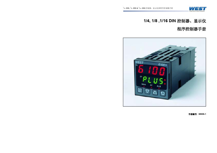
1/4, 1/8 ,1/16 DIN 控制器、显示仪 程序控制器手册
手册编号: 59305-1
1/4 -DIN, 1/8 -DIN & 1/16 -DIN 控制器、显示仪和程序控制器手册
本手册是对随机所带简易手册的补充,手册中的内容随时可能更改。恕不另行通知。 强烈建议在仪表安装时安装高压和低压保护装置以免仪表受损
7.4 产品信息显示模式 .....................................................25
7.4.1
操作指南 ..................................................................................................25
5.1 上电步骤 .............................................................21
பைடு நூலகம்
5.2 前面板及按键 .........................................................21
5.3 显示 21
4.30 输出 3 – 变送器电源 ...................................................20
5 上电 ........................................................................................................................... 21
6100说明书
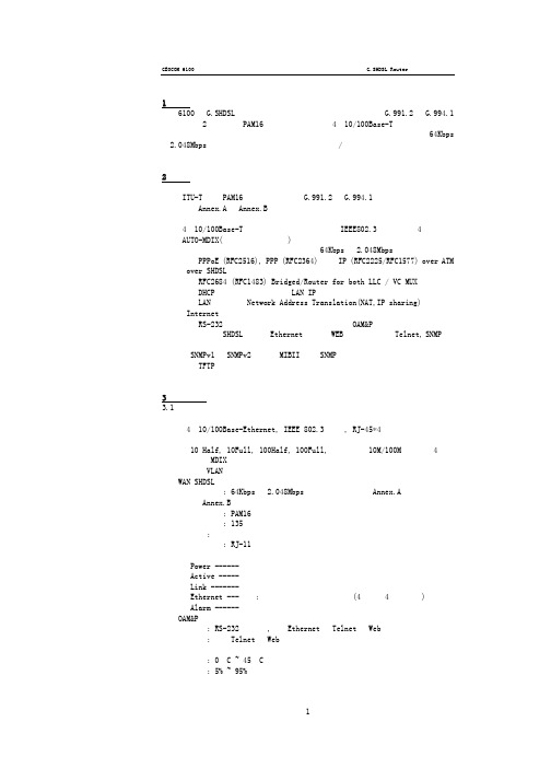
2、特性 ■ 一对双绞线上实现高速的同步对称速率数据传输。 ■ ITU-T 标准PAM16 线路编码,兼容G.991.2 和G.994.1 标准。 ■ 支持Annex.A 和Annex.B 操作模式。 ■ 内置式高级全态数据包监督防火墙。 ■ 4个10/100Base-T自适应的以太网端口,符合IEEE802.3标准,并且4口都支持
2) 根据WEB 浏览器的配置要求,PC 或NB 必须安装WEB 浏览器。IE 或NETSCAPE(注:
建议使用IE5.0 或NETSCAPE6.0,支持1024×768 分辨率)。
3) 检查超级终端接入程序。对串口操作台配置来讲使用VT100 终端仿真设置终端接
入程序。
4) 确定连接设置。用户需要知道服务商提供的以下参数:
GEOCOM 6100
G.SHDSL Router 快速配置说明书
1、概述 6100 是G.SHDSL(单对高速率数字用户线)的路由器。它符合G.991.2 和G.994.1
标准。采用2 线传输,PAM16 线路编码,并带有4个10/100Base-T自适应的交换口。 可满足企业和小型办公的需求。它在现有的单对铜线上可提供业务级,多程64Kbps —2.048Mbps 的传输速率,而且还集中了高端网桥/路由功能,允许用户把宽带的最 新技术用于他们日益增长的数据通信网络中。
6100说明

PTT和耳机话筒插孔位于机身两侧,机身上并未提供充电插孔。PTT按键上覆盖有橡胶,按键行程适中,手感不错。6100Plus采用流行的前后电池设计,一体化锂电池容量为1200MAH@7.4V,几乎是2R一倍半,这也是其4W—5W发射功率的后援保障。在包装中厂家提供了座式充电器,不像大部分进口业余手持对讲机座充需要另外高价选配。皮带卡是直接通过螺丝固定在电池板上的,坚固程度没有问题,只是如果有用户需要备两块垫板就需要2套皮带卡了。6100Plus的天线座为SMA的母头,这和大部分主流进口业余手持对讲机的接口一样,这就意味着用户可以方便地使用为业余电台设计的各种高增益天线了。很多商用对讲机采用SMA公头,正好与业余电台常用的设备相反,给换用天线带来麻烦。
6100Plus的信号强度表为真实有效的,不像有些国货只要打开静噪,不管是否收到信号信号表都会全显示,完全没有指示接收信号强弱的参考作用。我们实测了一下6100Plus在435.025MHz下的信号表情况,其S1&S2起表信号强度为—120dBm,随着信号的增强信号条以为2格为步进递增显示,最后一格S9稳定显示信号强度为-100dBm。
LT-6100Plus属于多功能小型对讲机,机身在同类对讲机中属于比较小的,握感不错,用于安全保卫场合外形虽不够威武,用于个人通信则比较讨巧。对于一些行业用户,LT-6重00Plus替代VX-2R用于专业场合不但费用会降低60%以上,而且由于LT-6100Plus的输出功率远大于VX-2R,所以通信距离更远,同时兼顾商业机的设计使得充电维护也更为方便。
LT6100Plus是在LT-6100基础上针对业余无线电市场的一款功能加强型手持对讲机,俗称“灵通6100plus”。该产品增加了很多个人业余无线电爱好者所期望的功能,同时兼顾专业市场。高发射功率、400MHz一470MHz全覆盖、真信号强度表、内置亚音编解码、标配语音加密、调频广播接收功能、标配锂电池都是这款对讲机的卖点所在,适中的价格加上众多功能卖点,使得它成为2007年度业余电台市场上国产手持对讲机中耀眼的明星,也成为入门级业余电台人员的首选设备之一。LT-6100Plus定位于单频段单通道多功能小型对讲机。
ST 6100 终端安装指南说明书

ST 6100 terminals are integrated IsatData Pro communications terminals manufactured by ORBCOMM. ORBCOMM distributes the terminals through Solution Providers who activate the terminal on the IsatData Pro network. The terminals are available with side or bottom connectors.This guide provides information required for a successful, reliable installation of the terminal on a vehicle, boat or other platform. This guide does not address the terminal’s commissioning procedures as these procedures vary depending upon the Solution Provider and their specific application.View of ST 6100 side connectorRequired ToolsInstallation of the terminal requires the following tools:•Drill and 5.5 mm drill bit•30 mm diameter hole punch or hole saw (bottom connector version only)•Screwdriver•Socket wrench setRequired MaterialsInstalling a terminal requires the following recommended materials. These materials do not ship with the terminal because they differ for each installation.•Qty 4 - M4 (8-32) 18-8 stainless steel screws (length depends on mounting surface thickness)•Qty 4 - M4 (8-32) nuts with 18-8 stainless steel flat and lock washers•Waterproof sealing tape•Dielectric grease•Qty 1 - Custom cable provided by your Solution Provider•Mating connector kit (ST100030-001)CableThe Solution Provider may provide a custom cable to connect to the terminal. Contact your Solution Provider if you did not receive a cable.Record the Mobile IDEach terminal has a unique serial number, termed a mobile ID, used by ORBCOMM to register it on the IsatData Pro network. This is a 15-digit alphanumeric identifier in the format "NNNNNNNNSKYXXXX" The mobile ID is located on the bottom of the terminal and on the shipping box. Record this number before the terminal is mounted. You need it later for commissioning the terminal on the network.Installation StepsCAUTION Most users install the terminals on a vehicle. It is very important for installers to install the terminals in a safe and secure way to avoid danger or damage topersons or property.Select the Mounting Location•Mount the terminal where it has a clear view of the sky/satellite. For a mobile installation, this means that it is preferable to install at the highest point on the vehicle or vessel where it has a clear view of the sky in all directions.•Mount the terminal on a flat surface for mobile installations such that the elevation angle does not change with rotation.Note:For fixed installations and maximum antenna gain, point the terminal’s LED in the direction of the satellite, and then rotate it 45 degrees clockwise.Figure 1 Recommended Direction for Maximum Antenna Gain•Mount the terminal so that the terminal’s line-of-sight with the sky is clear of obstructions.•Fasten the terminal securely so that it is not loose and does not move easily.•Mount the terminal on a solid, stable surface. If necessary, use a mounting bracket (not supplied) or other suitable support.•Ensure that any paint above the terminal is non-metallic and non-metallic flake, if the installation is under fiberglass or composite wind fairings.•Check that the terminal's cable reaches the power source before you drill any mounting holes.•Mount the terminal on the driver's side of the vehicle, if possible, when there is a possibility of strikes by overhanging tree branches.•Mount the terminal on a flat surface that is parallel to the ground but visible to the sky, for proper operation of the internal accelerometer. Record the position of the top surface (ORBCOMM logo) and connector face relative to the ground and the front or side of the vehicle as if you were sitting in the driver’s seat. This information is used later to set up the accelerometer service.Example: If the terminal is mounted horizontally on the vehicle roof such that the ORBCOMM logo is facing up and the cables are exiting towards the back of the driver, then record “top facing up andconnectors facing back”.Refer to the latest version of [T405] IsatData Pro Service API Ref for more details.•Mount the terminal on a surface that does not get hotter than the maximum operating temperature (+85°C). If the surface may get hotter, mount the terminal with a thermal barrier between it and the mounting surface.CAUTION Mount the terminal at least 20 cm (8 in.) away from humans.•DO NOT mount the terminal close to other electrical equipment due to possible radiated and/or conducted electromagnetic interference.•DO NOT mount the terminal close to radar or other communications antennas. Use the following guidelines:> 1 m from VHF/UHF antenna> 3 m from loop antenna> 4 m from MF/HF antenna> 5 m from other satellite antennasNot within a radar beam•DO NOT mount the terminal where water may build-up or collect.•DO NOT mount the terminal close to an exhaust pipe due to the excessive heat and the potential for the•DO NOT mount the terminal close to air horns or any tractor roof hardware (for example, emergency lights) that could interfere with satellite communications.•DO NOT install the terminal inside the truck under the roof liner.Install the TerminalOnce you have selected the mounting location, mount the terminal. Select either bottom connector mounting (Figure 2) or the side connector mounting (Figure 3) depending on the terminal’s connector type.The duplicate mobile ID labels, shipped with the terminal, can be placed on the asset where the terminal is mounted and/or on any customer paperwork. For outdoor applications these labels should be protected by applying the clear overlays provided.In some cases, the Solution Provider may provide a mounting bracket with the terminal. In this case, the following instructions are not required. Refer to the instructions with the mounting bracket.1)Use the drill template (Figure 8) to mark the location of the four mounting holes and the connector hole(if bottom connector). The orientation of the terminal with a bottom connector is not important.2)Fill the ribbed channel around the connector (Figure 4) with waterproof sealing compound (bottomconnector only). You can also apply waterproof sealing compound to the drilled mounting holes before inserting the screws.3)Secure the terminal in place with the mounting hardware using the screwdriver and socket set.CAUTION Do not over-tighten.Figure 2 Figure 3Bottom Connector ST 6100 Shown Side Connector ST 6100 Shown4)Cut off one end of the tube of dielectric grease. Adding the dielectric grease makes sure that there is awatertight seal. Figure 4 Terminal Connector5)Insert the tube into the male end of the mating connector andsqueeze the dielectric grease into the mating connecter opening(Figure 4) until it is full. Some dielectric grease will spill out.CAUTION Do not apply pressure to the cable/connectorduring the installation.6)Connect the cable connector to the terminal by aligning thecorresponding connector key slot (Figure 5) and gently squeezingtogether.CAUTION Do not force the connector pins to mate sincethis may damage the pins.Figure 5 Key SlotKey SlotLocking CollarFill with dielectric grease Apply waterproof sealing compoundST 6100 Terminal Installation Guide7)Tighten the cable connector with hand pressure by rotating the locking collar on the cable connectorclockwise. Do not use a wrench. A tactile click is felt when the collar is properly engaged.8)Wipe off any extra grease around the connector and wrap the mating connector with waterproof sealingtape if using the connector in changing weather conditions.Apply PowerBefore connecting the terminal to an external voltage source, ensure that the polarity is correct, and the voltage source is between 9 and 32 VDC. Refer to the connector pin assignment description. Connect the ground connection at the same time or before applying power. This is especially true when using the RS-232 lines along with power and ground.The terminal has an integral LED to indicate that the terminal has successfully powered on.The visual indicator (LED) does not indicate satellite status. Its only purpose is to confirm terminal power-on.Figure 6 Pin AssignmentsPin Functionality Pin Functionality1 RS-485 A2 RS-485 B3 GND4 VIN (9 to 32 VDC)5 I/O 026 I/O 037 I/O 01 8 I/O 049 RS-232 Tx (Output) 10 RS-232 Rx (Input)Figure 7 View of Terminal Male Connector (A) and Front View of Mating Connector (B)(A) (B)Register the TerminalOnce you apply power, the terminal goes into satellite search mode to acquire the IsatData Pro network. This activity may take a few minutes to complete. The terminals must complete registration to operate. Once the terminal synchronizes itself with the network, it sends a registration message to the IsatData Pro network. The terminal will not register until it has a clear line-of-sight to the satellite. The IsatData Pro network records the registration message and forwards the registration message to the u ser’s application. The IsatData Pro network sends an acknowledgement message over the satellite to the terminal. The terminal is now available to send and receive messages via satellite.Remember to indicate the orientation of the terminal’s acceleromete r in the terminal firmware.Pin 1Pin 1R9015 Version 03 5 © ORBCOMM ®ProprietaryFigure 8 Drill Template ST 6100CAUTIONBefore drilling check the template against actual hardware for dimensional accuracy. If it is not correct, DO NOT USE THIS TEMPLATE.Nominal Dimensions ShownR9015 Version 036© ORBCOMM ®ProprietaryCable Assembly InstructionsThis section provides the information necessary for the Solution Provider to assemble ST power/interface cables for the end-user. The mating connector kit (ST100030-001) does not ship with the terminal.The cable assembly procedures in this section are adequate for most installations. For particularly harshenvironments such as maritime installations, use a cable with molded backfill as described in the Blunt Cut cable section later in this document. Please contact Customer Support if you need recommendations for a cable manufacturer. Note:It is recommended you choose a raw cable with the following properties:* The terminal accepts input ranges of 9 to 32 VDC. If your application requires extended cable lengths, it is necessary to calculate the cable voltage drop to determine if the terminal is receiving at least 9 V (with 1.7 A draw). Large cable voltage drops might adversely affect terminal operation.* Cable jacket and internal conductor installation rated for minimum temperature range of -40°C to 85°C (-40° to +185°F), and UV compliant where exposure to UV is expected.Note:For reliable operation, shield all cables used for power and data connections to the terminal.Figure 9 Basic Connector Parts for Soldering ConfigurationRequired Tools and MaterialsThe following tools and materials are required to build the cable using this method:• A cable 1 appropriate for the terminal’s environment • A knife• A wire stripper • Solder• A fine-tip soldering iron• A flexible high temperature silicone sealant for outdoor exposureCable Assembly Steps1) Use a knife to cut and remove the outer jacket of the cable, 20 mm from the end (Figure 10) and removeany foil shielding.CAUTIONBe careful not to nick the wire insulation.2)Use a wire stripper to remove 5 mm of insulation from the wires (Figure 10).1For cables exposed to extreme temperatures and sun, select a cable with a thermal rating of -40°C to +85°C (-40 to +185°F)and a UV resistant jacket.Connector BodyCoupling Ring Back ShellSealing NutFigure 10 Recommended Stripping Length3)Twist the ends tightly to prevent stranded wires from fraying.CAUTION Do not solder dip.4)Slide the following items over the cable in sequence and as shown in Figure 11: a sealing nut, a back shelland a coupling ring.Figure 11 Cable with Sealing Nut, Back Shell and Coupling RingCAUTION Ensure that the black back shell cable grommet is present inside the cable grip area (Figure 12) and the red gasket is present and oriented with flatface visible as shown in Figure 13.Figure 12 Cable GrommetFigure 13 Red GasketCoupling RingBack Shell Sealing NutR9015 Version 03 7 © ORBCOMM® Proprietary5)Using a soldering iron and solder, tin the wires and solder them to the connector solder cups (Figure 14) asper the proper pinout.Figure 14 Wires and Solder Cups6)Ensure the O-ring is in place over the connector body.Figure 15 O-Ring over Connector Body7)Slide the coupling ring over the connector body and give it a twist to prevent it from falling off.8)Use silicone sealant to completely fill the end of the connector and the area between the wires.Figure 16 Silicone in the Connector9)Slide the back shell up the cable as close as possible to the connector body and fill it with silicone sealant.Figure 17 Silicone in the GrommetR9015 Version 03 8 © ORBCOMM® ProprietaryR9015 Version 039© ORBCOMM ®Proprietary10) Assemble the back shell to the connector body and wipe away any excess sealant. To aid in tightening theback shell, align the coupling ring key feature with the slot in the connector body (Figure 18).Figure 18 Key Features in the Coupling Ring and Connector Body11) Apply sealant over the cable exit area.Figure 19 Cable Exit Area12) Assemble the sealing nut over the back shell until the cable grip makes full contact with the perimeter ofthe cable jacket. Wipe away any excess sealant.Figure 20 Assembled Sealing NutBlunt Cut CableThis cable connects the ST terminal to external I/O lines and serial ports. There are 10 pins on this blunt cut cable; two connect the terminal to an RS-232 console serial port or an RS-485, four wires to connect to external I/O lines, and one each for ground and voltage. The cable has an over-molded connector, a floating drain wire and is available in two models, either terminated or unterminated to ground.Figure 21 Face View of Terminal Blunt Cut Cable ConnectorTable 1 Terminal Mating Blunt Cut Cable Color CodeR9015 Version 03 10 © ORBCOMM® ProprietaryST 6100 Terminal Installation GuideR9015 Version 03 11 © ORBCOMM ® Proprietary Figure 22 Raw Cable DetailsOverall ShieldAluminum FoilOuter Shield DrainPVC JacketBlack, UV Stable2 x Power/Ground2 x RS-232 2 x RS-485Twisted Pair I/O DrainI/O ShieldAluminum Foil4 x I/O+1.613.836.2222*******************。
Symantec SNAC 6100中文手册
表 1-1
Enforcer 设备的硬件规格
部件
说明
基本部件
521,2.8GHz/1MB 高速缓存,P4 800MHz 前端总线
内存
1GB DDR2,533MHz 2x512 单队列 DIMM
硬盘驱动器
160GB,SATA,1 英寸,7.2K RPM 硬盘驱动器
Policy Manager Installation 介绍如何安装PolicyManager,配置数据库和建立复制机制。 Guide(《Policy Manager 安 装指南》)
Policy Manager Administration Guide (《Policy Manager 管理指 南》)
Symantec™ Network Access Control Enforcer 6100 系列 7 设置 Symantec Network Access Control Enforcer 6100 系列
若需要了解有关在网络中部署 Enforcer 设备的其他规划信息,请参阅 Symantec Network Access Control Enforcer 6100 Series Setup and CLI Reference Guide (《Symantec Network Access Control Enforcer 6100 系列设置和 CLI 参考指 南》)。 安装 Enforcer 设备包括以下两个任务:
查找详细信息的位置
Symantec Network Access Control 套件包含下列文档:
4 Symantec™ Network Access Control Enforcer 6100 系列 开始使用 Symantec Network Access Control Enforcer 6100 系列
- 1、下载文档前请自行甄别文档内容的完整性,平台不提供额外的编辑、内容补充、找答案等附加服务。
- 2、"仅部分预览"的文档,不可在线预览部分如存在完整性等问题,可反馈申请退款(可完整预览的文档不适用该条件!)。
- 3、如文档侵犯您的权益,请联系客服反馈,我们会尽快为您处理(人工客服工作时间:9:00-18:30)。
Auto focus color camera moduleSN-CMD6100(DN)/ZXX user's manualDrafting Examination Decision深圳市景阳科技股份有限公司2010-11-172011-4-272011-6-82011-9-20DAY NIGHT菜单及VISCA兼容协议里增加BURST项增加INTY,AGCCNT查询指令增加指令:开机时是否显示ID,波特率,协议增加了Optical Zoom Position Table 指令修正2011-11-28ver1.7ver1.3ver1.4ver1.5ver1.6ver1.0ver1.1ver1.22010-5-262010-6-32010-9-30首次发布参数修正VISCA兼容协议里增加调菜单和菜单状态查询指令版本日期修正内容1. 产品特性··························page42. 技术规格··························page43. 一体化模组型摄像机机芯接口定义···············page54. 一体化模组型摄像机机芯通讯协议···············page65. 一体化整机摄像机通讯协议··················page116. 一体化整机摄像机接口定义··················page137. OSD菜单结构 ························page148. SN-ZMC6100DN/Z22机芯结构尺寸图 ··············page15● 内置一体化光学变焦镜头内置一体化光学变焦镜头,自动、手动聚焦可选,变倍时能保持良好的跟踪聚焦。
● 高解析度、高灵敏度采用1/4" SONY Super HAD Ⅱ CCD,水平解析度最高可达540TVL。
最低照度0.3Lux(彩色模式),0.05Lux(黑白模式,可选带可移动式滤光片)。
● 日&夜功能切换(可选)内置可移动滤光片切换装置,白天模式时阻止红外线通过以获得清晰逼真的色彩,晚上 模式时可以让红外线通过以获得更低的照度。
● OSD菜单操作内置OSD菜单操作功能,方便摄像机参数的调整。
● 两种通讯协议控制模式内置了两种不同的通讯协议控制模式:一体化模组型摄像机机芯采用RS-232 TTL通讯方 式兼容SONY一体机机芯协议;一体化整机摄像机采用RS-485通讯方式支持PELCO-D协议。
● 内置AD键盘输入接口当使用一体化整机摄像机时,AD键盘接口使得一体机的后控板的设计非常简单。
● 特殊图像效果支持水平镜像,正负片等功能。
● 多种电子快门速度1/50~1/100000s共72档电子快门速度可选,适合拍摄高速移动物体。
技术规格表背光补偿聚焦方式供电电源工作温度自动/PUSH/手动f=4mm~88mm f=3.3mm~89.1mm f=3.4mm~122.4mm自动型号SN-ZMC6100DN/Z22SN-ZMC6100DN/Z27SN-ZMC6100DN/Z36像素PAL :752(H )×582(V )/ NTSC :768(H )×494(V )光学变焦22倍光学变焦27倍DC12V 300mA 信噪比视频输出上、中、下、左、右区域可调黑白、镜像、负片1/50~1/100000s自动图像效果电子快门白平衡增益控制0℃~50℃1/4" SONY Super HAD ⅡCCD540线0.3Lux(彩色模式),0.05Lux (黑白模式,With IR cut filter1.0±0.2Vp-p 光学变焦36倍>50dBRS-232 TTL / RS-4859600bps焦距范围通信波特率成像器件镜头倍数清晰度最低照度通信方式一体化模组型摄像机机芯接口定义J5以SN-ZMC6100DN/Z22机芯为例底视图9Pin FPC座接口定义Pin NO.123456789VIDEO_OUT GND RXD TXD NC NCDefinitionVIDEO_GND +12V GND一体化模组型摄像机机芯通讯协议(兼容SONY VISCA协议)一、通讯格式1.波特率:9600bps2.数据位:83.起始位:14.停止位:15.校验位:无6.通讯接口:RS-232 TTL二、信息包结构本通讯协议的基本单元被称为信息包,信息包的第一个字节称之为报头,报头包含了发送者和接收者的地址。
例如:值为16进制数81H的报头表示地址为0的控制器发送信息给地址为1的摄像机;如果要发发送给地址码为2的摄像机信息时,则报头就为82H。
在命令表里报头为8X,X代表摄像机的地址。
从地址码为1的摄像机返回的信息包的报头为90H,地址码为2的摄像机返回的信息包的报头为A0H。
有些命令可以同时被所有的摄像机接收,这些命令被称为广播命令;使用广播命令时,信息包的报头为88H。
当FFH出现时,表示信息包结束。
三、命令、查询、错误消息命令:发送操作命令到摄像机。
查询:使用查询命令查询摄像机的当前状态。
Command Packet NoteInquiry 8X QQ RR ... FF QQ1) = Command/Inquiry,RR2) = category code1) QQ = 01 (Command), 09 (Inquiry)2) RR = 00 (Interface), 04 (camera 1), 06 (Pan/Tilter), 07 (camera 2)X = 1 to 7: camera address错误消息:当某个命令或查询不能被执行或执行失败时,摄像机返回错误消息X0 6Y 02 FF四、命令表CAM_ZoomDirect 8x 01 04 47 0p 0q 0r 0s FF pqrs: Zoom PositionDown 光标所在项参数改变(增加)8x 01 04 00 08 FF 光标下移Left 光标所在项参数改变(减少)开机时是否显示ID,波特率,协议InfoDis_SwitchON 81 01 04 15 04 FF Off81 01 04 15 05 FF 8x 01 04 00 04 FF CommentsCommand Set Enter 调出菜单或确认Right MenuWide(Standard)8x 01 04 08 03 FF8x 01 04 00 01 FFUp 8x 01 04 08 02 FF Stop8x 01 04 08 00 FF 光标上移Stop8x 01 04 07 00 FF 8x 01 04 07 03 FFpqrs: Focus PositionNear(Standard)Tele(Standard)8x 01 04 07 02 FF Far(Standard)Command Packet AddressSet Broadcast 88 30 01 FFCommand One Push Trigger 8x 01 04 18 01 FF CAM_Focus Manual Focus 8x 01 04 38 03 FF Auto Focus 8x 01 04 38 02 FF Direct8x 01 04 48 0p 0q 0r 0s FF Low8x 01 04 58 03 FF AF Sensitivity Normal 8x 01 04 58 02 FF pqrs: Zoom Positiontuvw: Focus PositionZoom Trigger AF 8x 01 04 57 02 FFCAM_AFMode Interval AF 8x 01 04 57 01 FF Normal AF 8x 01 04 57 00 FF CAM_WB 8x 01 04 47 0p 0q 0r 0s 0t 0u 0v 0w FFCAM_ZoomFocus Direct CAM_Initialize Lens8x 01 04 19 01 FF Lens Initialization Start ATW 8x 01 04 35 04 FF Auto Tracing White Balance Auto (AWB)8x 01 04 35 00 FF Normal AutoCAM_AEpq: Shutter Position Automatic Exposure mode Shutter Priority Automatic Exposure mode8x 01 04 39 0A FF Shutter Priority Reset 8x 01 04 0A 00 FF Full Auto8x 01 04 39 00 FFCAM_Shutter8x 01 04 0A 02 FF Reset后快门变为1/250Up Down 8x 01 04 0A 03 FFMirror Image ON/OFFCAM_LR_Reverse CAM_Gain(Limit)Protocol_Switch8x 01 04 00 05 FF 8x 01 04 00 06 FF 8x 01 04 00 07 FF Direct 8x 01 04 4A 00 00 0p 0q FF 8x 01 04 61 02 FFReset 8x 01 04 0C 00 FF 8x 01 04 4C 00 00 0p 0q FF pq: Gain Position On Off 8x 01 04 61 03 FF切换到PELCO D协议Reset后Gain变为0dB Up 8x 01 04 0C 02 FF Down 8x 01 04 0C 03 FFDirect Color_Burst 转黑白时色副载波信号打开或关闭ON 8x 01 04 A1 02 FF Off 8x 01 04 A1 03 FF五、查询命令表pq: Bright Position,范围:00H~FFH Direct 8x 01 04 42 00 00 0p 0q FF UpDownReset 8x 01 04 02 00 FF 8x 01 04 02 03 FFUp 8x 01 04 02 02 FF Off 8x 01 04 33 03 FFCAM_PictureEffectOffCAM_BacklightOn8x 01 04 33 02 FFNeg.Art Down 8x 01 04 0D 03 FF Command Reset Command Packet 8x 01 04 0D 02 FF Comments CAM_BrightCAM_Aperture(Sharpness)Direct Command SetCAM_AutoICRAuto Infrared Mode ON/OFF8x 01 04 51 02 FFCAM_ICROn8x 01 04 01 02 FFInfrared Mode ON/OFF a)Off 8x 01 04 01 03 FF Title Set28x 01 04 73 00 mm nn pp qq00 00 00 00 00 00 FFmm: Vposition, nn:Hposition pp: fix 00, qq:Blink8x 01 04 73 01 mm nn pp qqrr ss tt uu vv ww FFmnpqrstuvw: Setting ofDisplay Characters (1st to10st Character)CAM_Display8x 01 04 15 02 FF OnOff8x 01 04 51 03 FF Off On8x 01 04 15 03 FF (8x 01 06 06 03 FF)(8x 01 06 06 02 FF)CAM_TitleTitle Display ON/OFFTitle Set18x 01 04 15 10 FF On/Off 8x 01 04 63 02 FF8x 01 04 0D 00 FF Title Setting Clear (8x 01 06 06 10 FF)8x 01 04 4D 00 00 0p 0q FF 8x 01 04 63 00 FFPicture Effect SettingBack Light Compensation ON/OFF Aperture Control pq: Aperture Gain范围:00H~02H,分别代表LOW(默认)、MID、HIGH 8x 01 04 74 03 FFTitle Set38x 01 04 73 02 mm nn pp qqrr ss tt uu vv ww FFmnpqrstuvw: Setting ofDisplay Characters (11thto 20th Character)Title Clear 8x 01 04 74 00 FF On 8x 01 04 74 02 FFOffInquiry Command Command Packet Inquiry PacketCommentsy0 50 0p 0q 0r 0s FF y0 50 02 FF y0 50 03 FFCAM_FocusPosInq pqrs: Zoom Position CAM_ZoomPosInq Auto Focus Manual FocusCAM_FocusModeInq 8x 09 04 38 FF 8x 09 04 47 FF pqrs: Focus Position CAM_AFSensitivity Inq8x 09 04 58 FFAF Sensitivity Normal AF Sensitivity Lowy0 50 0p 0q 0r 0s FF 8x 09 04 48 FF y0 50 03 FFy0 50 02 FF查询命令表续Menu OFF y0 50 00 FF 8x 09 04 74 FFNeg.Art On pq: Gain Position mn:倍数;pq:bit7-bit4:默认0;bit3:IRIS功能;bit2:ICR功能;bit1:1:百万像素,0:标清;bit0:1:PAL,0:NTSC;rs tu: 版本号;vw:默认0y0 50 07 FF Communication Menu ON y0 50 04 FFExposure Menu ON Hide Menu ONCAM_IDInq 8x 09 04 22 FF y0 50 0p 0q 0r 0s FFpqrs: Camera ID Off(8x 09 06 06 FF)y0 50 03 FF Off 8x 09 04 01 FFCAM_ICRModeInq CAM_TitleDisplayM odeInq y0 50 03 FF CAM_DisplayModeIn q 8x 09 04 15 FF y0 50 02 FF CAM_LR_ReverseMod eInq y0 50 02 FFOn 8x 09 04 63 FFCAM_PictureEffect ModeInq Off y0 50 03 FF Off y0 50 00 FF8x 09 04 42 FFy0 50 00 00 0p 0q FF pq: Aperture Gain 8x 09 04 61 FFpq: Bright Position CAM_BacklightMode Inq y0 50 02 FFOn Offy0 50 03 FFCAM_GainPosInq 8x 09 04 4C FF y0 50 00 00 0p 0q FF CAM_AEModeInq 8x 09 04 39 FFy0 50 0A FFy0 50 00 FFZoom Trigger AF pq: Shutter Position Auto(AWB)ATWShutter Priority Full AutoNormal AF Interval AF VerInq y0 50 02 ff ON y0 50 03 ff OFFy0 50 02 FFy0 50 02 FFOn 8x 09 04 51 FFCAM_AutoICRModeIn q y0 50 03 FF y0 50 00 20 mn pq rs tu vwFF8x 09 00 03 FFColor_BurstInq AGCCNT 8x 09 04 A4 FF8x 09 04 A1 FFINTY0--INTY4(屏幕上下左右中的亮度)Step2: 8x 09 04A2 FFStep1:8x 09 04A3 FFOff y0 50 03 FFCAM_AFModeInq y0 50 00 FFCAM_WBModeInq y0 50 04 FF 8x 09 04 35 FFOn y0 50 02 FFOff y0 50 02 FFOn MenuStatusInq 8x 09 04 A0 FF y0 50 08 FFy0 50 02 FF 8x 09 04 4A FF CAM_ShutterPosInq CAM_BrightPosInq 8x 09 04 4D FF y0 50 00 00 0p 0q FF CAM_ApertureInq y0 50 01 FFy0 50 00 FF8x 09 04 57 FF 8x 09 04 33 FFy0 50 00 00 0p 0q FF Main Menu ON y0 50 01 FF y0 50 06 FF Other Menu ONy0 50 05 FF WB Menu ON y0 50 03 FFDayNight Menu ON y0 50 02 FF Picture Menu ON 90 50 0m 0n 0p 0q 0r 0s 0t 0u 0v 0w FF mn:INT0,pq:INT1,rs:INT2,tu:INT3,vw:INT4 (LSB)90 50 0m 0n FF mn:AGG gain controlmn:INT0,pq:INT1,rs:INT2,tu:INT3,vw:INT4 (MSB)六、命令参数表Shutter Speed Shutter Speed PAL(NTSC)PAL(NTSC)Gain(dB)00H 1/50(60)2FH 1/31K 00H 001H 1/120(100)30H 1/32K 01H 102H 1/25031H 1/33K 02H 203H 1/50032H 1/34K 03H 304H 1/60033H 1/35K 04H 405H 1/70034H 1/36K 05H 506H 1/80035H 1/37K 06H 607H 1/90036H 1/38K 07H 708H 1/100037H 1/39K 08H 809H 1/110038H 1/40K 09H 90AH 1/120039H 1/41K 0AH 100BH 1/13003AH 1/42K 0BH 110CH 1/14003BH 1/43K 0CH 120DH 1/15003CH 1/44K 0DH 130EH 1/16003DH 1/45K 0EH 140FH 1/17003EH 1/46K 0FH 1510H 1/18003FH 1/47K 10H 1611H 1/190040H 1/48K 11H 1712H 1/200041H 1/49K 12H 1813H 1/3K 42H 1/50K 13H 1914H 1/4K 43H 1/60K 14H 2015H 1/5K 44H 1/70K 15H 2116H 1/6K 45H 1/80K 16H 2217H 1/7K 46H 1/90K 17H 2318H 1/8K 47H 1/100K18H 2419H 1/9K 19H 251AH 1/10K 1AH 261BH 1/11K 1BH 271CH 1/12K 1CH 281DH 1/13K 1DH 291EH 1/14K 1EH301FH 1/15K 20H 1/16K 21H 1/17K 22H 1/18K 23H 1/19K 24H 1/20K 25H 1/21K 26H 1/22K 27H 1/23K 28H 1/24K 29H 1/25K 2AH 1/26K 2BH 1/27K 2CH 1/28K 2DH 1/29K 2EH 1/30KShutter Position ShutterPosition Gain PositionOptical Zoom Position Table [Hexadecimal] Ratio start end10x00000x078020x07810x0a4030x0a410x0E0040x0E010x116050x11610x146060x14610x174070x17410x1B0080x1B010x1DE090x1DE10x2160100x21610x2500110x25010x2860120x28610x2B20130x2B210x2E60140x2E610x3220150x32210x3540160x35410x37E0170x37E10x39B0180x39B10x3B30190x3B310x3D40200x3D410x3E60210x3E610x3fff220x40000x4000一、通讯格式1.波特率:9600bps2.数据位:83.起始位:14.停止位:15.校验位:无6.通讯接口:RS-485二、信息包结构Byte1Byte2Byte3Byte4Byte5Byte6Byte7SynchAddressCommand Command Data1Data2Check三、命令表1.调预置位95(调菜单)Byte1Byte2Byte3Byte4Byte5Byte6Byte7 0xff Address 0x000x070x000x5f Check例如地址码为1,则校验和为0x67调预置位96(将当前协议切换为一体化模组型摄像机机芯通讯协议)Byte1Byte2Byte3Byte4Byte5Byte6Byte7 0xff Address 0x000x070x000x60Check 2.UPByte1Byte2Byte3Byte4Byte5Byte6Byte70xffAddress 0x000x080x00SPEED Check 2.DOWNByte1Byte2Byte3Byte4Byte5Byte6Byte7 0xff Address 0x000x100x00SPEED Check4.LEFTByte1Byte2Byte3Byte4Byte5Byte6Byte7 0xffAddress0x000x040x00SPEEDCheck5.RIGHTByte1Byte2Byte3Byte4Byte5Byte6Byte7 0xffAddress 0x000x020x00SPEED Check一体化整机摄像机通讯协议(兼容PELCO D协议)Byte6原本为控制球机时的速度参数(变化的数值);这里可为任意数,仅用于计算校验合时使用,DOWN ,LEFT ,RIGHT 指令同。