低温多晶硅TFT-LCD异军突起
低温多晶硅薄膜晶体管液晶显示技术(LTPSTFT

低温多晶硅薄膜晶体管液晶显示技术(LTPS TFT北方彩晶集团谷至华2005年1月由于多晶硅电学性能上的优势,可以实现玻璃基板上的驱动集成(CHIP ON GLASS 简写COG),系统集成(SYSTEM ON GLASS 简写SOG),可以现实更高分辨率,更快的响应速度,稳定性,可靠性更高的显示器件,低温多晶硅是TFT-LCD产业发展的方向。
该领域涉及主要产品及技术主要产品:手机、数码相机、便携视听产品,车载移动终端,高级计算机显示器等。
技术:低温多晶硅薄膜晶体管液晶显示器(Lp-Si TFT-LCD)技术涉及集成电路设计、信号转换、薄膜技术、液晶显示技术、激光技术、界面处理技术等,低温多晶硅薄膜晶体管液晶显示器是目前世界上最新的技术,代表了一个国家的平板显示产业的技术水平。
1.技术及产品发展现状LTPS TFT物理电学特性较a-Si TFT性能更加优异,具有更高的集成度,可以实现驱动电路的集成,甚至计算机系统的集成,外接元件大量减少,器件的性能得到大幅度提升,更加稳定,更加可靠,而器件的成本会更加低。
是平板显示技术的发展方向。
但是由于技术难度比较大,特别是大面积激光退火技术具有非常大的工艺挑战性。
目前只有日本东芝和松下在新加坡投资的4.5五代线可以生产17英寸的多晶硅液晶显示器,其他公司基本上只能处理手机和移动终端的小尺寸的多晶硅。
多晶硅TFT-LCD还是投影显示领域的核心技术之一。
是数字化电影院建设的关键部件,在教育、办公和大屏幕投影家庭影院领域也有巨大的市场。
随着LTPS技术的逐渐成熟,在未来的10年中,LTPS将成为平板显示领域的核心技术,有机电致发光,厚膜无机电致发光都需要LTPS技术,大尺寸液晶电视也期待着LTPS的应用。
LTPS作为平板显示器产业的重大潜在核心技术受到国际上科研和产业界的高度重视。
通过对早期TFT-LCDa-Si TFT生产线改造,投入少,可以使产业迅速升级。
目前国际上3代一下的非晶硅TFT-LCD生产线基本上都已经改造成为多晶硅生产线。
TFT LCD产业现状
TFT LCD产业现状tft-lcd产业现状tft(thinfilmtransistor,薄膜晶体管)lcd(liquidcrystaldisplay,液晶显示器)是有源矩阵类型液晶显示器(activematrixlcd,am-lcd)中的一种。
它具有低功耗、轻薄易用、高亮度、高对比度、高响应速度、无辐射、无闪烁、适用范围宽、生产成品率高、易于集成化和更新换代等特点,目前已成为平板显示产业的主流技术之一。
小到智能手机、数码相机、电子表,大到平板电视、各种尺寸的显示器,都在大量采用tft-lcd屏。
tft-lcd的主要原材料包含液晶、玻璃基板、背光模组、彩色滤光片、偏光片、驱动电路、化学气体与材料、外框、各类薄膜及其他材料。
其中,液晶、玻璃基板、滤光片、偏光片等关键原材料主要掌控在日本、韩国、德国、美国企业手中。
我国台湾地区生产了全球50%以上的大尺寸tft-lcd驱动ic,PCB了全球80%以上的大尺寸tft-lcd驱动ic,并且就是背光模组的关键产地。
主流的tft面板有a-si(amorphoussilicon,非晶硅)tft技术和ltps(lowtemperaturepoly-silicon,低温多晶硅)tft技术。
其中大部分采用a-sitft制造技术,一些小尺寸产品采用ltps技术。
ltpstft与a-sitft相比能够提供更亮、更精细的画面,并且更轻薄、更省电。
目前,液晶显示已经占有了平板表明市场的主导地位,为同时实现响应速度更慢、分辨率更高、色彩更多样、尺寸更大的显示屏,企业和研究机构仍在不断研发代莱技术,存有特定光电性质的无机、有机膜材料,用作液晶分子价值观念的高分子材料,以及背光led等新材料。
(2)我国tft-lcd产业发展现状1998年从日本引入第一条1代生产线掀开了我国tft-lcd产业的发展历史,2021年随着京东方全面收购韩国现代电子的液晶业务,我国tft-lcd产业发展也步入快车道,各地生产线项目纷纷上马,至目前为止已经初具规模,构成了为北京为核心的环渤海产业基地;以合肥、南京、苏州和昆山为核心的长江三角洲产业基地;以深圳、广州为代表的珠江三角洲表明产业基地;以成都为核心的西部产业基地。
LTPS低温多晶硅技术浅析
LTPS低温多晶硅技术浅析一、LTPS简介低温多晶硅(Low Temperature Poly-silicon;LTPS,以下以LTPS代称)是平板显示器领域中的又一新技术。
继非晶硅(Amorphous-Silicon,以下以a-Si代称)之后的下一代技术。
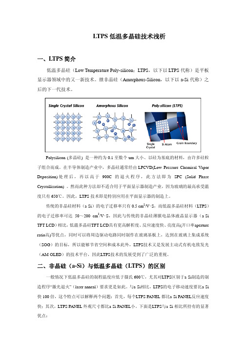
Polysilicon (多晶硅) 是一种约为0.1至数个um大小、以硅为基底的材料,由许多硅粒子组合而成。
在半导体制造产业中,多晶硅通常经由LPCVD(Low Pressure Chemical Vapor Deposition)处理后,再以高于900C的退火程序,此方法即为SPC (Solid Phase Crystallization) 。
然而此种方法却不适合用于平面显示器制造产业,因为玻璃的最高承受溫度只有650℃。
因此,LTPS技术即是特別应用在平面显示器的制造上。
传统的非晶硅材料(a-Si)的电子迁移率只有0.5 cm2/V‧S,而低温多晶硅材料(LTPS)的电子迁移率可达50~200 cm2/V‧S,因此与传统的非晶硅薄膜电晶体液晶显示器(a-Si TFT-LCD)相比,低溫多晶硅TFT-LCD具有更高解析度、反应速度快、亮度高(开口率aperture ratio高)等优点,同时可以将周边驱动电路同时制作在玻璃基板上,达到在玻璃上集成系统(SOG)的目标,所以能够节省空间和成本此外,LTPS技术又是发展主动式有机电致发光(AM-OLED)的技术平台,因此LTPS技术的发展受到了广泛的重视。
二、非晶硅(a-Si)与低温多晶硅(LTPS)的区别一般情况下低温多晶硅的制程温度应低于摄氏600℃,尤其对LTPS区别于a-Si制造的制造程序“激光退火”(laser anneal)要求更是如此。
与a-Si相比,LTPS的电子移动速度要比a-Si 快100倍,这个特点可以解释两个问题:首先,每个LTPS PANEL 都比a-Si PANEL反应速度快;其次,LTPS PANEL 外观尺寸都比a-Si PANEL小。
ltps工艺技术介绍
ltps工艺技术介绍LTPS工艺技术,全称为低温多晶硅技术(Low Temperature Poly-Silicon),是一种在低温下制备多晶硅的工艺技术。
它在显示屏制造领域广泛应用,特别是在智能手机和平板电脑的屏幕制造上。
LTPS工艺技术相对于传统的TFT-LCD工艺技术具有很多优势,下面我们来介绍一下。
首先,LTPS工艺技术可以制造出更高分辨率和更高精度的屏幕。
多晶硅的晶粒更小,可以在同样的面积上装下更多的晶粒,从而提高分辨率。
同时,LTPS工艺技术可以制造出更细腻的像素点,使显示效果更加细腻和真实。
其次,LTPS工艺技术可以提高屏幕的响应速度。
在传统的TFT-LCD工艺技术中,液晶分子移动的速度有限,导致刷新速度较慢,容易出现动态模糊现象。
而LTPS工艺技术采用了更高质量的多晶硅材料,可以使晶体管开关速度更快,从而提高屏幕的响应速度,减少动态模糊现象的发生。
另外,LTPS工艺技术可以节省能源和降低功耗。
在传统的TFT-LCD工艺技术中,需要使用背光模组来提供光源,而LTPS工艺技术采用了自发光的设计,可以直接通过薄膜晶体管激活像素,减少了能量传递过程中的损耗,从而达到节能和降低功耗的效果。
此外,LTPS工艺技术还可以制造出更薄更轻的屏幕。
相比于传统的TFT-LCD工艺技术,LTPS工艺技术所需要的驱动电路更小更精简,可以减少屏幕的厚度和重量,提高设备的便携性。
最后,LTPS工艺技术还可以提高屏幕的可靠性和寿命。
多晶硅具有更好的稳定性和耐用性,可以抵抗氧化和老化的影响,从而延长屏幕的使用寿命。
同时,LTPS工艺技术可以减少杂散电流和漏电流的发生,提高屏幕的稳定性和可靠性。
总之,LTPS工艺技术在显示屏制造领域具有广泛的应用前景。
它可以制造出更高分辨率、更高精度、更快响应速度、更节能、更薄轻、更可靠的屏幕,满足了现代科技产品对屏幕显示质量的要求,推动了智能手机和平板电脑等设备的发展。
随着技术的进步和创新,相信LTPS工艺技术在未来还将有更多的突破和应用。
低温多晶硅

Low-Temperature Polysilicon Thin-Film Transistor Driving with Integrated Driver for High-Resolution Light Emitting Polymer Display Mutsumi Kimura,Ichio Yudasaka,Sadao Kanbe,Hidekazu Kobayashi,Hiroshi Kiguchi,Shun-ichi Seki,Satoru Miyashita,Tatsuya Shimoda,Tokuro Ozawa,Kiyofumi Kitawada,Takashi Nakazawa,Wakao Miyazawa,and Hiroyuki OhshimaAbstract—A high-resolution low-temperature polysilicon thin-film transistor driven light emitting polymer display(LT p-Si TFT LEPD)with integrated drivers has been developed.We adopted conductance control of the TFT and optimized design and voltage in order to achieve good gray scale and simple pixel circuit.A p-channel TFT is used in order to guarantee reliability in dc bias.An inter-layer reduces parasitic capacitance of bus lines. Because of the combination of the LT p-Si TFT and LEP,the display is thin,compact,and lightweight,as well as having low power consumption,wide viewing angle,and fast response.I.I NTRODUCTIONL OW-TEMPERATURE polysilicon thin-film transistors (LT p-Si TFT’s)have been utilized to drive liquid crystal displays(LCD’s)[1]–[3].There are many candidates for active matrix devices,i.e.,single-crystal Si MOS FET, amorphous Si TFT,high-temperature p-Si TFT,LT p-Si TFT, other semiconductor devices,etc.Among the candidates,only the LT p-Si TFT has performance high enough to compose integrated driver circuits and the capability of being fabricated on a large transparent substrate simultaneously.Additionally, it has already been reported that the LT p-Si TFT can also be fabricated on a plastic substrate[4].These advantages of the LT p-Si TFT allow the present great successes to come true in LCD’s,not only in research and development,but also in the market.However,the LT p-Si TFT is not only for LCD’s.The LT p-Si TFT’s have great potential even for other displays which have integrated driver circuits and are large sizes[5]. On the other hand,light emitting polymers(LEP’s)[6]–[8] promise to achieve thin,compact,lightweight,and inexpen-sive displays.Moreover,the display can have low power consumption,wide viewing angle,and fast response.Until now,for LEP displays(LEPD’s),mainly static and passive matrix driving methods have been utilized.However,for high-resolution displays consisting of many pixels,needless to say, the static method cannot drive the LEP.The passive matrix Manuscript received October1,1998;revised June1,1999.The review of this paper was arranged by Editor J.Hynecek.M.Kimura,I.Yudasaka,S.Kanbe,H.Kobayashi,H.Kiguchi,S. Seki,S.Miyashita,and T.Shimoda are with Base Technology Research Center,Seiko Epson Corporation,Owa Suwa392-8502,Japan(e-mail: kimura.mutsumi@exc.epson.co.jp).T.Ozawa,K.Kitawada,T.Nakazawa,W.Miyazawa,and H.Ohshima are with L Project,Seiko Epson Corporation,Owa Suwa392-8502,Japan. Publisher Item Identifier S0018-9383(99)09015-2.method cannot drive the LEP,either[9],because the high-resolution display demands high voltage in the short scanning period in order to achieve the required average brightness,and this high voltage results in a lower power efficiency of the light emitting.Accordingly,instead of the static or passive matrix driving method,an active matrix driving method is better for high-resolution display as the pixels may be driven close to their best power efficiency point.Since the LEPD is not a cell structure,i.e.,liquid layer and two sandwiching substrates,it does not need the second substrate.Moreover,the LEPD does not need a backlight,light guide,polarizer,diffuser,etc.,which are used in the LCD. Therefore,the display consists of one substrate,peripheral drivers,and many contacts between them.The next target is to eliminate the peripheral drivers and contacts.If the peripheral drivers are replaced by monolithic drivers integrated on the substrate,not only can the peripheral drivers be eliminated, but the number of contacts can also be decreased.The display is dramatically reduced to only one substrate.As a result,the display will be exceedingly thin,compact,lightweight,and inexpensive.Because of the advantage of the wide viewing angle,the LEPD is suitable for direct view applications.Most applica-tions such as these are large size displays.In the case of the current LEPD structure,since the polymers and cathode metal are serially stacked on the substrate and light emits through the substrate,the substrate must be transparent.Therefore,for the device to drive the LEPD,the capability of fabrication on a large transparent,i.e.,glass or plastic,substrate is needed. In conclusion,in order to drive the high-resolution LEPD, the active matrix device is needed and it must have enough performance to compose integrated drivers and have the ca-pability to be fabricated on the large transparent substrate, simultaneously.Only the LT p-Si TFT can satisfy these demands.Therefore,the objective of our development in this paper is to confirm how the LT p-Si TFT is suitable to drive the high-resolution LEPD.A high-resolution LT p-Si TFT LEPD with integrated drivers is designed,fabricated,and evaluated[10].We adopted conductance control of the TFT and optimized design and voltage in order to achieve good gray scale and simple pixel circuit.A p-channel TFT is used in order to guarantee reliability in dc bias.An inter-layer reduces0018–9383/99$10.00©1999IEEEFig.1.Cross-sectional view of the LT p-Si TFT LEPD.LT p-Si TFT’s are fabricated the same as the TFT-LCD.Light comes through the glass substrate. Since the TFT-LEPD needs only some thinfilms on one substrate,very thin, compact,lightweight,and inexpensive displays can be achieved.The function of the inter-layer is to distance the cathode and to reduce parasitic capacitance of bus lines.parasitic capacitance of bus lines.The display is thin,compact, lightweight,low power consumption,wide viewing angle,and fast response.II.S TRUCTUREA cross-sectional view of the TFT-LEPD is shown in Fig.1.First,on a glass substrate,LT p-Si TFT’s,bus lines, and pixel electrode are fabricated the same as they are in the TFT-LCD[1],[2].A50-nm a-Si is formed by LPCVD of Si at425KrF excimer laser.Phosphorous ions for n-channel TFT’s and boron ions for p-channel TFT’s are implemented with a dose of the10cm order at an energy of several ten keV.These impurities are activated at 300C for4h.The TFT characteristics are shown in Fig.2.Mobility for n-channel TFT and p-channel TFT is 120cm s and40cm s,respectively.In the case of the LCD,the ITO pixel electrode is used in order to apply voltage to the liquid crystal.On the other hand,in the case of the LEPD,the ITO pixel electrode is used as an anode in order to supply current to the LEP.Next,an adhesive layer,inter-layer are fabricated.The function of the SiOplasma surface operation is done in order to improve the wettability of the surface of the polyimide and ITO.After that,LEP layer consisting of a conductive polymer and a light emission layer,and a cathode metal are fabricated in succession[8].First,polyethylene dioxythiophene/polystylene sulphonate(PEDOT/PSS)are dispersed in water and spin-coated.Since the surface of the substrate is wettable by OFig.3.Pixel circuit of the TFT-LEPD.A pixel is composed of a switching and driving TFT,a storage capacitor,and an LEP diode.Conductance dependence of the driving TFT is used in order to control gray scale.By this method,the pixel circuit can be simple.and reduce degradation caused by self-heating[12],[13].The scan and signal drivers are integrated around the image area on the substrate and their workings are the same as those used in TFT-LCD’s.The mechanism for scanning,i.e.,for transferring each signal voltage to the corresponding storage capacitor,is similar to that used in TFT-LCD’s.The only difference is that the signal voltage stored in the capacitor does not have to be ac,but can be dc,because the LEP diode is driven by dc current and the driving TFT should control the LEP diode by dc voltage.Therefore,it is possible to reduce the amplitude of the signal voltage and scan voltage.The signal voltage stored in the capacitor is also applied to the gate terminal of the driving TFT.The gate voltage controls conductance of the driving TFT and anode voltage depends on the relationship between the resistance of the driving TFT and LEP diode.That is,by varying signal voltage,current through the LEP from the supply line via the anode to the cathode and light emission can be modulated.In the bright state,since the resistance of the driving TFT is negligible compared to that of the LEP diode,there is little voltage drop and wasted power consumption in the driving TFT.The power reduction in the bright state is very meaningful because the current is larger than other states. There are only two TFT’s in a pixel.This structure is conventional for current consuming devices,such as the LEP diode,and there are some disadvantages,for example,nonuni-formity caused by variation of the characteristic between the driving TFT’s.However,we chose this structure because the simplicity is very practical when we avoid the yield rate problem in mass production.Next,the design and voltage were optimized.The driving TFT cannot work in the saturation region for all the gate voltages even if its design parameter is varied.There are two reasons.Thefirst reason is low drain voltage.In order to reduce the power consumed in the driving TFT in the bright state,the resistance of the driving TFT should benegligible Fig.4.Operation point analysis of the driving TFT and LEP diode.Hori-zontal and vertical axis are voltage of the terminal between the driving TFT and the LEP diode and current through the driving TFT and the LEP diode. The characteristics of the driving TFT corresponding to each gate voltage and the characteristic of the LEP diode are overlapped.The cross points of the characteristics mean operational points of the pixel equivalent circuit. compared to the resistance of the LEP diode.This means that the voltage drop between the drain and the source terminal,i.e., drain voltage,is rather small.In addition,since the efficiency of the light emission from the LEP becomes very high and its threshold voltage becomes very low,recently,only about 5V must be applied to the LEP diode for sufficient light emission.The second reason is that,as shown in Fig.2,the LT p-Si TFT has no saturation region defined clearly,i.e.,a flat characteristic which is independent of the drain voltage, because of many defects in the channel[14].If a TFT worked in the saturation region,it would be easy to calculate the current because the current would mainly depend only on the gate voltage.However,since the TFT works in the nonsaturation region,it is very difficult to calculate the current by analytical calculation.The reason is as follows. The current depends on not only the gate voltage but also the drain voltage.The drain voltage is decided by the relationship of the resistance between the driving TFT and the LEP diode. This relationship is not decided until the current is decided because both the TFT and the LEP diode are nonlinear electric devices for applied voltages.Because of such a complicated mechanism,operational point analysis or circuit simulation by a computer is needed to perform the design.Fig.4shows operational point analysis of the pixel equiva-lent circuit to achieve gray scale.The horizontal axis is voltage of the terminal between the driving TFT and the LEP diode, which is drain voltage of the driving TFT and anode voltage of the LEP diode,simultaneously.The vertical axis is drain current of the driving TFT,which is same as the current through the LEP diode.The characteristics of the driving TFT corresponding to each gate voltage,which is the signal voltage stored in the storage capacitor,are overlapped.The characteristic of the LEP diode is also overlapped.The cross points of the characteristics of the driving TFT and the LEP diode mean operational points of the pixel equivalent circuit for each gate voltage.Circuit simulation with a TFT and LEP model[15]was done in order to design the driving TFT and LEP diode circuit including gray scale.These models are extracted from the measured data.Fig.5shows a simulated current–voltageFig.5.Simulated current–voltage (I 0V )characteristic of the driving TFT and LEP diode.Horizontal and vertical axis are signal voltage and current through the LEP diode,respectively.Gray scale can be acquired by optimizing all the design parameters.Signal voltage can be adjusted within a range of less than 5V.TABLE IS PECIFICATIONS AND D ESIGN P ARAMETERS OF THE TFT-LEPD.D ESIGNP ARAMETERS W ERE O PTIMIZED BY C IRCUIT S IMULATIONS .A H IGH -R ESOLUTIONLT p-Si TFT LEPD WITH I NTEGRATED D RIVERS H AS B EEN FABRICATED()characteristic of the equivalent circuit consisting of the driving TFT and LEP diode.The horizontal axis is signal voltage,which is applied to the gate terminal of the driving TFT.The vertical axis is current through the driving TFT and LEP diode.Gray scale from the bright state via the halftone state to the dark state can be acquired.By such analyses and simulations,for the given area of the LEP,the design of the driving TFT,i.e.,width and length,is optimized.Signal voltage can be adjusted within a range of less than 5V,which may achieve very low power consumed in video signal circuit in the peripheral controller.After that,the entire design of the TFT-LEPD,i.e.,the switching TFT,storage capacitor,etc.,is decided.All the optimized design parameters and specifications of the TFT-LEPD are shown in Table I.B.P-Channel TFT for Reliability in DCIn order to ensure the reliability of the driving TFT even when dc voltage is applied,a p-channel TFT is used.Fig.6shows a comparison of the reliability by measurement between an n-channel and p-channel TFT.Initial transfer characteristics and those after dc stress,i.e.,gate voltage 20V,drain voltage 0V,temperature 70m,while that of SiOm.From thesevalues,capacitance between the signal line and cathode is 3.1pF.By adding other capacitance,total capacitance of the signal line is 10.5pF.Resistance of the signal line itself is330at most.Therefore,the time constant of the signal line is on the order of 10ns.This panel is designed for the point-at-time driving scheme [16],which means that during application of scan voltage,each signal voltage is applied sequentially.The selecting time for one signal line is 240ns.Since the time constant is enough smaller than the selecting time,correct signal can be applied to the signal line.D.OthersThe LEP layer,i.e.,the conductive layer and the light emitting layer,is not patterned.However,crosstalk of light emission between pixels does not occur.The reason is asFig.7.View overlooking the TFT-LEPD.Because of no backlight,light guide,polarizer,diffuser,peripheral drivers,etc.,the TFT-LEPD can be lightweight,thin,andcompact.Fig.8.Photographs of pixels and electroluminescence from the pixels.Since the light emission area ratio is at most 12%,reflection from cathode metal is reduced and contrast can be improved if the rest of the pixel is covered with a light shield layer.follows.Since the electric resistivity of the conductive layer is about 1k/sq and its resistance betweenpixelsis.The resistance is much higher than the LEP diode resistance,the orderof.Moreover,the electric resistivity of the light emitting layer between pixels is still higher than that of the conductive layer.As a result,the LEP diode can be supposed to be electrically separated between each pixel.IV.R ESULTSA high-resolution LT p-Si TFT LEPD with a scan and signal integrated driver has been fabricated.The specifications have already been shown in Table I.A view overlooking the TFT-LEPD is shown in Fig.7.No backlight,light guide,polarizer,diffuser,and peripheral drivers are needed.The number of contacts between the peripheral controller and the panel is reduced to only 27.Twenty-six of the contacts are through a flexible tape and one contact is through a wire pasted on the cathode.Consequently,the TFT-LEPD can be exceedingly lightweight,thin,and compact,as shown in Table I.Here,the second glass substrate is used only for encapsulation of the LEP and supporter,which can be eliminated easily in the nearfuture.Fig.9.Display image of the TFT-LEPD.Green monochrome display image is acquired.Neither nonuniformity nor crosstalkoccurs.Fig.10.Measured and simulated gray scale.Brightness is normalized by the maximum value.The measured gray scale is similar to the simulated one.It is found that good gray scale from the bright state via the halftone state to the dark state can be acquired.Photographs of pixels and electroluminescence from the pixels are shown in Fig.8.The light emission area ratio,i.e.,the ratio between light emission area and whole area in a pixel,is at most 12%.In spite of the small ratio,there is no serious problem because all light comes from the light emission area,no light loss occurs,and power is not wasted.On the contrary,the small ratio can reduce reflection from cathode metal.If the rest of the pixel is covered with a light shield layer,all reflection from the display can be reduced and contrast can be improved.A display image of the TFT-LEPD is shown in Fig.9.Here,a green monochrome display is acquired.Neither nonunifor-mity caused by the parasitic capacitance of the bus lines nor crosstalk between pixels occurs.Measured and simulated gray scale is shown in Fig.10.Here,brightness is normalized by the maximum value.The measured gray scale is similar to the simulated one.It is found that good gray scale from the bright state via the halftone state to the dark state can be acquired.The achieved power consumption with the voltage and current are listed in Table II.The power consumed in the integrated driver is 20mW.In order to achieve brightness of 100Cd/mTABLE IIV OLTAGE ,C URRENT AND P OWER OF THE TFT-LEPD.T OTAL P OWER C ONSUMPTION OF THE TFT-OELD IS C OMPARABLE WITH T HAT OF THE TFT-LCD.C URRENT D ENSITY OF THE LEP I S 18mA/cm 2AND E FFICIENCY OF THE LEP I S A BOUT 3Lm/Wimage is darker or smaller,the power consumption is still less.It is comparable with or smaller than that of the TFT-LCD.V.C ONCLUSIONA high-resolution LT p-Si TFT LEPD with a complete set of the integrated drivers has been developed and published for the first time in the world.We adopted conductance control of the TFT and optimized design and voltage in order to achieve good gray scale and simple pixel circuit.A p-channel TFT is used in order to guarantee reliability in dc bias.An inter-layer reduces parasitic capacitance of bus lines,and so on.Because of the combination of the LT p-Si TFT and LEP,the display is thin,compact and light weight.Additionally,the display has low power consumption,wide viewing angle,and fast response,which are achieved only from the nature of the LEP.The image is uniform and crosstalk does not occur.The fabrication processes of the TFT are the same as those for the LCD except for some additions and LEP processes.Therefore,if the TFT-LEPD proves to be superior to the TFT-LCD for some applications,present LT p-Si TFT fabrication lines for the LCD’s can be easily changed to those for the LEPD.A CKNOWLEDGMENTThe authors wish to thank Dr.R.H.Friend,Dr.J.H.Burroughes,Dr.C.R.Towns,Dr.K.Heeks,Dr.J.C.Carter,and Dr.I.Grizzi of Cambridge Display Technology Ltd.,for fruitful collaboration of the TFT-LEPD and fabrication of the LEP.R EFERENCES[1]H.Ohshima,“Overview of polysilicon technology,”in Proc.EuroDisplay Workshop ,1996,pp.17–20.[2]S.Inoue,M.Matsuo,K.Kitawada,S.Takenaka,S.Higashi,T.Ozawa,Y.Matsueda,T.Nakazawa,and H.Ohshima,“425 C poly-Si TFT technology and its application to large size LCD’s and integrated digital data drivers,”in Display ,1995,pp.339–342.[3]Y.Matsueda,T.Ozawa,M.Kimura,T.Ito,K.Kitawada,T.Nakazawa,and H.Ohshima,“A 6-bit-color VGA low-temperature poly-Si TFT-LCD with integrated digital data drivers,”in SID Dig.Tech.Papers ,1998,pp.879–882.[4]N.D.Young,R.M.Bunn,R.W.Wilks,D.J.McCulloch,G.Harkin,S.C.Deane,M.J.Edwards,and A.D.Pearson,“AMLCD’s and electronics on polymer substrates,”in Proc.Euro Display ,1996,pp.555–558.[5]T.P.Brody,“Birth of the active matrix,”Inform.Display ,vol.10,pp.28–32,1997.[6]R.H.Friend,“Organic electroluminescent displays,”in SID SeminarLecture Notes ,1998,vol.2,F-1,pp.1–27.[7]J.H.Burroughes,D.D.C.Bradley,A.R.Brown,R.N.Marks,K.Mackay,R.H.Friend,P.L.Burns,and A.B.Holmes,“Light-emitting diodes based on conjugated polymers,”Nature ,vol.347,pp.539–541,1990.[8]J.C.Carter,I.Grizzi,S.K.Heeks,cey,tham,P.G.May,O.Ruiz de los Panos,K.Pichler,C.R.Towns,and H.F.Wittmann,“Operating stability of light-emitting polymer diodes based on poly(p-phenylene vinylene),”Appl.Phys.Lett.,vol.71,pp.34–36,1997.[9]R.M.A.Dawson,Z.Shen,D.A.Furst,S.Connor,J.Hsu,M.G.Kane,R.G.Stewart,A.Ipri,C.N.King,P.J.Green,R.T.Flegal,S.Pearson,W.A.Barrow,E.Dickey,K.Ping,C.W.Tang,S.V.Slyke,F.Chen,J.Shi,J.C.Sturm,and M.H.Lu,“Design of improved pixel for a polysilicon active-matrix organic LED display,”in SID Dig.Tech.Papers ,1998,pp.11–14.[10]T.Shimoda,H.Ohshima,S.Miyashita,M.Kimura,T.Ozawa,I.Yudasaka,S.Kanbe,H.Kobayashi,R.H.Friend,J.H.Burroughes,and C.R.Towns,“High-resolution light emitting polymer display driven by low-temperature polysilicon thin-film transistor with integrated driver,”in Display ,1998,pp.217–220.[11]S.Morozumi,K.Oguchi,S.Yazawa,T.Kodaira,H.Ohshima,and T.Mano,“B/W and color LC video displays addressed by poly Si TFT’s,”in SID Dig.Tech.Papers ,1983,pp.156–157.[12]S.Inoue and H.Ohshima,“New degradation phenomenon in widechannel poly-Si TFT’s fabricated by low temperature process,”in IEDM Tech.Dig.,1996,pp.781–784.[13]S.Inoue,H.Ohshima,and T.Shimoda,“Analysis of threshold voltageshift caused by bias stress in low temperature poly-Si TFT’s,”in IEDM Tech.Dig.,1997,pp.527–530.[14]G.A.Armstrong,S.Uppal,S.D.Brotherton,and J.R.Ayres,“Dif-ferentiation of effects due to grain and grain boundary traps in laser annealed poly-Si thin-film transistors,”Jpn.J.Appl.Phys.,vol.37,pp.1721–1726,1998.[15]M.Kimura,T.Ozawa,K.Ozawa,and H.Ohshima,“Numerical TFTmodel for circuit simulation using spline interpolation with transforma-tion by y =x +log(x ),”in Dig,Tech.Papers AM-LCD ,1998,pp.181–184.[16]M.Kimura,T.Ozawa,and H.Ohshima,“Simulation of horizontalcrosstalk in point-at-time scheme with matrix parametric model,”in Dig.Tech.Papers AM-LCD ,1996,pp.317–320.Mutsumi Kimura was born in Japan on October 5,1966.He received the B.S.and M.S.degrees in physical engineering from Kyoto University,Japan,in 1989and 1991,respectively.He joined Matsushita Electric Industrial Co.,Ltd.,Moriguchi Osaka,in 1991.In 1995,he joined Seiko Epson Corporation,Owa Suwa,Japan,where he has been working on TFT simulator development and TFT-LEPD development at the Base Technology Research Center.Ichio Yudasaka was born in Nagano,Japan,on March 22,1948.He received the B.S.degree in atomic nuclear engineering from Tohoku University,Japan,in 1971.He joined Hitachi Co.,Ltd.,Hitachi,Japan,in 1971.In 1979,he joined Seiko Epson Corporation,Owa Suwa,Japan,where he has been working on R&D of p-Si TFT at the Base Technology Research Center.Sadao Kanbe was born in Gunma,Japan,in May 1947.He received the B.S.degree in chemical engineering from Tokyo Institute of Technology,Japan,in 1971.In 1972,he joined Seiko Epson Corporation,Owa Suwa,Japan,where he has been working on R&D of materials for display.Hidekazu Kobayashi was born in Nagano,Japan,on November 8,1960.He received the B.S.and M.S.degrees in synthetic chemistry from Kyoto University,Japan,in 1983and 1985,respectively.In 1985,he joined Seiko Epson Corporation,Owa Suwa,Japan,where,until 1997,he was working on liquid crystal development.He is currently working on OELD development at the Base Technology Research Center.Hiroshi Kiguchi was born in Nagano,Japan,on January7,1966.He received the B.S.degree in chemistry from Shizuoka University,Japan,in1989.In1989,he joined Seiko Epson Corporation,Owa Suwa,Japan,where he has been working on development of ink-jet technologies for industry at the Base Technology Research Center.Shun-ichi Seki was born in Nagano,Japan,on June6,1968.He received the B.S.and M.S.degrees in physics from Science University of Tokyo, Japan,in1992and1994,respectively.He had been working on pie-conjugated pigment and photosensitive proteins in halobacteria at the Institute of Physical and Chemical Research,Riken, Tsukuba,Japan.In1997,he joined Seiko Epson Corporation,Owa Suwa, Japan,where he has been working on development of ink-jet technologies for LEP at the Base Technology Research Center.Satoru Miyashita was born in Nagano,Japan,on September1,1958. He received the B.S.degree in applied chemical engineering from Keio University,Japan,in1981.In1982,he joined Seiko Epson Corporation,Owa Suwa,Japan,where he has been working on functional materials research and novel process development.He is a Research Manager at the Base Technology Research Center.Tatsuya Shimoda was born in Tokyo,Japan,in1952.He received the B.S. and Ph.D.degrees from University of Tokyo,Japan,in1977and1987, respectively.In1977,he joined Seiko Epson Corporation,Owa Suwa,Japan.Since then,he has been involved in researching and developing functional materials and thin-film devices,such as rare-earth magnets,magneto-optical media, semiconductor laser,p-Si TFT,organic EL,etc.He is now a Director of the Base Technology Research Center,and a Guest Professor of Japan Institute Science and Technology(JAIST).Tokuro Ozawa was born in Yamanashi,Japan,on December13,1966.He received the B.S.degree in image science from Chiba University,Japan,in 1990.In1990,he joined Seiko Epson Corporation,Owa Suwa,Japan,where he has been working on the design of TFT-LCD at L Project.Kiyofumi Kitawada was born in Nagano,Japan,on July15,1964.He received the B.S.and M.S.degrees in plasma physics from Kanazawa University,Japan,in1991.In1991,he joined Seiko Epson Corporation,Owa Suwa,Japan,where he has been working on R&D of polysilicon TFT technologies at L Project. Takashi Nakazawa received the B.S.degree from Nihon University,Japan, in1981.In1981,he joined Seiko Epson Corporation,Owa Suwa,Japan,where he has been working on R&D of polysilicon TFT technologies,and is a Manager of L Project.Wakao Miyazawa was born in Nagano,Japan,on August22,1951.In1970,he joined Seiko Epson Corporation,Owa Suwa,Japan,where he has been working on R&D of polysilicon TFT technologies,and is a Manager of L Project.Hiroyuki Ohshima was born in Okayama,Japan,on May5,1956.He received the B.S.degree in engineering from Tokyo University,Japan,in 1979.In1979,he joined Seiko Epson Corporation,Owa Suwa,Japan,where he has been working on R&D of active-matrix devices,and is a Director of L Project.Mr.Ohshima received SID Outstanding Contributed Paper Awards in1984 and1985,and SID Special Recognition Award in1995.。
TFT-LCD显示技术

详细描述
TFT-LCD显示屏的响应速度取决于液晶分子 的运动速度。为了提高响应速度,可以采用 新型液晶材料、优化驱动电路等方式。此外, 采用动态背光调节技术也可以在一定程度上 改善响应速度问题。
色彩表现力不足
总结词
相对于OLED等其他显示技术,TFT-LCD显 示技术在色彩表现力方面存在不足。
详细描述
视角限制
总结词
TFT-LCD显示技术的视角限制是其固有 缺点之一。
VS
详细描述
由于TFT-LCD显示屏的视角限制,从不同 角度观看时,色彩和亮度可能会发生变化 ,影响观看效果。为了解决这个问题,可 以采用广视角膜或者广视角技术,如IPS 、VA等,以扩大可视角度。
响应速度慢Байду номын сангаас
总结词
TFT-LCD显示技术的响应速度慢可能会影响 动态图像的显示效果。
厚度薄、体积小
厚度薄、体积小
轻便易携带
TFT-LCD显示器采用了薄型化和集成化的设 计,使得显示器在厚度和体积上都相对较小。 这种设计使得TFT-LCD显示器在空间受限的 环境中具有优势,如移动设备、便携式电脑 等。
由于TFT-LCD显示器体积小、重量轻,用户 可以轻松地将它携带到不同的地方。这种便 携性使得TFT-LCD显示器在移动办公、远程 会议等场景中具有广泛的应用价值。
功耗低
功耗低
TFT-LCD显示器采用了高效的背光调节技术 ,能够在不同亮度下保持较低的功耗。此外 ,TFT-LCD显示器还具有智能电源管理系统 ,可以根据实际需要自动调节背光亮度,进 一步降低功耗。
节能环保
低功耗的特性使得TFT-LCD显示器在节能环 保方面具有优势。用户在使用这种显示器时 可以节省能源,减少对环境的负担。这种环 保特性使得TFT-LCD显示器受到了许多用户
应用于低温多晶硅薄膜晶体管液晶显示器之新型互补电流镜式模拟缓冲放大器

Th r p s dCCM n lg b fe k su eo -y ea d a -y ec re tmir rt p uf rt c iv ep o o e a ao u frma e s f p t p n nn t p u r n - ro -y eb fe oa h e e a lr ev la e s n .Th r p s d b fe o sn tn e a a i r n x e n lc n r lsg as O i la a g o tg wig ep o o e u f rd e o e d c p ct sa d e t r a o to in l,S t e - o t rsc mp c iea dg o ie rt . u e o a tsz n o d l a iy n Ke r s a ao u f r c m p e e t r u r n ir r d t rv r TP TFT- CD ywo d : n lg b fe ;o lm n a y c re tm ro ; a ad ie ;L S; L
WA NG n — sn , N i — n , Fa g H ig LI Ch h Yig CH AN G u g Pe g 。 U H a — e H n — n LI nW n
( eat et fEeti l n ier gadG a u t ntueo pol t cE gneig,h n D p rm n l r a E gnei n rd aeIs tt fO t e r n i r o c c n i e ci e n C u gHs gU ies y, f i n nvri t Gh t m , ) ,
维普资讯
第3 卷 1
第1 期
TFT-LCD技术简介
TFT-LCD技术1 TFT LCD技术发展历史晶体管的发明对半导体行业来说,是个划时代的事件。
作为晶体管的一种,TFT的发明是在与LCD没有任何联系的情况下发生的。
1971年,虽然有人提出用TFT驱动LCD的概念,但是并没有引起人们的注意。
直到1979年,开发出了TFT LCD,但是当时由于用无源矩阵的方法也可以驱动100条左右的扫描线,因此还是很多人对TFT LCD没有看好。
在LCD画面的数十万个画素上都作TFT,在当时的半导体技术水平来看,简直是“痴人做梦”。
进入80年代以后,在TN模式LCD上很难实现显示更多信息量的要求,因此很多人(LCD技术人员,而不是半导体技术人员)在液晶材料和液晶模式上想找出答案。
1983年左右,人们终于找到了答案—新的液晶模式STN LCD。
由于STN模式非常巧妙的解决了TN模式在100条扫描线以上出现画质急剧下降的问题,整个LCD业界几乎都投入到STN技术开发和产品开发。
80年大后期,市场上大量出现了STN产品,还出现了类似于笔记本电脑的文字处理器(Word Processor)。
但是对于彩色化、液晶电视等新的需求,STN模式显然力不从心(响应速度慢,灰度表示较困难)。
很多技术人员开始转向新的解决方法。
虽然TFT LCD的技术开发没有停止过,但是整个LCD业界开始把目光转向TFT LCD还是上个世纪80年代中期以后的事。
上个世纪80年代正好是日本半导体行业的全盛期,而且比较有趣的是几乎所有的拥有半导体部门的日本企业都参与了TFT LCD产业。
因为TFT的工艺与DRAM 有很大的类似性,因此虽然没有LCD的技术储备,日本很多半导体企业还是参与了这个行业。
其实韩国的三星电子、LG飞利浦、现代都拥有或拥有过半导体部门;台湾的TFT LCD企业(友达)也与半导体有关系。
下面的两个表各自描述TFT的技术发展史和LCD的技术发展史。
在1971年TFT技术和LCD技术曾经有过交点,但是没有“成功”的结合;到了1981年开始这两个技术才真正结合并开始发芽开花了。
- 1、下载文档前请自行甄别文档内容的完整性,平台不提供额外的编辑、内容补充、找答案等附加服务。
- 2、"仅部分预览"的文档,不可在线预览部分如存在完整性等问题,可反馈申请退款(可完整预览的文档不适用该条件!)。
- 3、如文档侵犯您的权益,请联系客服反馈,我们会尽快为您处理(人工客服工作时间:9:00-18:30)。
T制造业 中的第一 与应 用潜 力 凸现 ,市场 前 景不 容 形 ,跃 居全球 I
小觑 。
T 丁 F 具有广 延性 , aS F 在 —i 丁 T 位 , 业链 涉及半导体 、 产 光学 、化 的基础上研 发 出L P . T ST 丁 T S L P F
世 代 线
母板尺寸
0 ms 继 而 在液 晶玻 璃 基板 上 完成 半导 亮 度 6 0流 明 ,响应 时间 8 。 另有 1 项 属于 L P F —C 7 T ST TL D晶 T T L D产 业是一 个典型 的技术 圆厂家的 , F —C 体 芯 片系统集 成 S G,实现显 示 O 改进aS T 丁 .i F 在性能 上
( ) 咖
4 G
60 8 8 x8 0
45 .G
70x2 3 5 0 X1 0
7 G
17 2 0 80x 20 26 40 1 0 x2 0
l 0 ×l 5 l 0 5 0 l0 20 3 0 Xl 0
维普资讯
低温多晶硅 T T L D异军突起 F Ie
口 韩工
平 板显 示 器正 逐步 取代 阴极 射线 管 C T成 为显 示器 产业 的主 R 流 ,尤 以液 晶 显示 器所 占比重 最
L P F —C T ST T L D技 术
T T L D生产 线主 要 以其玻 F —C
内藏 电路
拟开 关、驱 动器
A D转换 器 、定时控制器 、外部存储器 、 / 图形 接 口
DS P PC U
是 由大小 不足 1 “m的多晶颗粒形
p s 材料 的晶 粒尺 寸与 薄膜 —i
TFT
.
开发 新产 品。
成 的 ,其 电子 迁 移 率 可 达 5 制 备温 度有 关 .而 晶粒 大小 又直 0~ —i 2 0m ..比 aS F 0c / S v —i T的05 接影 响到pS 薄膜 的电子迁移 率 。 T .~1 产 —i c /. 出许 多 , m S v 高 因而 L P F — 目前 , 业化 降低pS材料 生长温 T ST T
L D除具备 与 aS F —C C — i T L D相似 度 的最 有 效方 法有 两类 ,一 是准 T L P F —C T ST T L D产 品的研 发 及量产 化 主要 集 中在 中小 屏液 晶 显示 器 方面 .采 用线 性激 光结 晶
L P F — C 产 T ST T L D
学 等诸 多领 域 ,甚 至誉 为 T T. F
L D晶圆产业 。 C
据 Dipa e rh报 告 ,在 s lyS ac 大 ,其 中薄 膜 晶体 管 液 晶显 示器 璃 母基 板 的尺 寸面 积来 划分 ,它 2 0 年至 2 0 年 ,全球 总共将有 05 07 的发 展速 度十 分惊 人 ,如表 1 所 T T L D 占绝对优 势 ,生产 技术 F —C 4 个 T T L D投 资项 目 , 中 3 7 F —C 其 0 示 。5 G以上线主 要用作 切割制作 进入 第八代 世代线 的 8 G。另一方 项 是有 关现有或 新建 的 aS F . — i T T 电脑监视器和 大尺 寸 电视液 晶屏 , 面 , F  ̄ 备工艺也 在不断 改进之 TT a J L D 晶圆厂 的 ,通过 简化 工艺 以 C 随着 7 G生产线产能 大量 释放 , 7 3 中 , 非晶硅 aS T T基础上 , 在 —i F 研
及 选用 较少 或较 低成 本 的原 材料 英寸 以上的 4 英 寸 、 7 2 4 英寸将 成 发 低 温 多晶硅 L P ( o e T S L w T m. 或 零组 件方 式 ,以期 有 效提 升 工 为主导产 品 , 制水平达 8 英 寸 , 艺 良品率 与产能 ,同时 降低 生产 研 2 p rtr oySl o ) eaueP l ic n 、高 温 多晶 i 8度 2 01 硅 HT S P 、连续 晶界 硅 C GS技术 , 其宽视 角 1 0 ,对 比度 1 0 :. 成 本 , 主要 目标 针对大尺 寸市场;
第 一 代 2 0 年 第 二 代 20 ・03年 00 0 120
约 10 0 4 移位寄存器 、模 102 0 0 —0 3
第 三 代 2 0-05年 0 420
2 03 0 0 —0 1 . 5
第 四 代 2 0 年 以后 06
304 0 0 —0 <1 . 0
粗估投 资规模
( 美元) 亿
8 1 2 l 2~ l 4 2 0 2 5~ 3 0 3 5— 4 0
2 M r 0 围 南 8 a h 06 c2 希子 协 : 誊。 .
维普资讯
工 艺 发 展 进 程
T 迁移率(m . 丌 c /s v) T 设计规划( m) 丌
L 的薄 型 、 轻量 、 高可靠 性 、 高精 细 分 子激 光退火 E A技 术 ,对等 离 ECVD 化 等特 性 之外 .还 具 有分 辨率 更 子体 增 强 化 学气 相 淀积 P
—i L 高 ,可 满足印刷 字体 分辨率 要求 , 方法 制备 的 as 材料 ,进 行 E A 响应速度 更快 . 亮度高 ( 即开 口率 形成 ps 材料 :其二 是采 用 N 金 —i i
及驱 动 电路 的集成 化 ,由 aS 向 与 资本 双 密集 的行业 ,巨额 投资 存 在 的局 限性 ,主 要 目标 针对 移 —i L P F —C T ST T L D发 展 的技 术优 势 新 生产 线和 技术 规格 升级 如 影随 动 终端应用 的中小尺寸液 晶市 场。