PT7C4363P中文资料
PT7C4337中文资料

Time Counter .............................................................................................................................................................................. 9 Days of the week Counter ......................................................................................................................................................... 10 Calendar Counter ...................................................................................................................................................................... 10 Alarm Register .......................................................................................................................................................................... 11 Alarm Function ........................................................................................................................................................................... 12 I2C Bus Interface............................................................................................................................................................................. 14 Overview of I2C-BUS .................................................................................................................................................................. 14 System Configuration ................................................................................................................................................................. 14 Starting and Stopping I2C Bus Communications ..................................................................................................................... 15 Slave Address .............................................................................................................................................................................. 17 Maximum Ratings........................................................................................................................................................................... 19 Recommended Operating Conditions ........................................................................................................................................... 19 DC Electrical Characteristics......................................................................................................................................................... 20 AC Electrical Characteristics......................................................................................................................................................... 21 Mechanical Information ................................................................................................................................................................. 22
贴片晶体管参数代码查询uvwxyz
BCR133T
Sie
N
SC75
npn dig 50V 0.1A 10k+10k
WCs
BCR133U
Sie
N
SOT457
npn dig 50V 0.1A 10k+10k
WCs
BCR133W
Sie
N
SOT323
npn dig 50V 0.1A 10k+10k
WCs
BCR133S
Sie
DN
SOT363
参数及代换型号
W0F
TSDF1205RW
Tfk
WQ
SOT343
12GHz npn 5mA 4V
W1s
BFT92
Sie
N
SOT23
BFQ51/BFQ76
W1s
BCR10PN
Sie
DP
SOT363
pnp/npn dig 0.1A 10k+10k
W2
TSDF1220RW
Tfk
WQ
SOT343
12GHz npn 6V 20mA
dg RF mosfet
U1E
3SK254E
Nec
UQ
SOT343
dg RF mosfet
U1G
3SK253G
Nec
UQ
SOT143
dg RF mosfet
U1G
3SK255G
Nec
UQ
SOT343
dg RF mosfet
U2
BCX20
Phi
N
SOT23
BC338
U2t
BCX20
Phi
N
SOT23
NPTC021KFXC-RC;NPPC021KFXC-RC;NPPC031KFXC-RC;NPTC031KFXC-RC;NPTC041KFXC-RC;中文规格书,Datasheet资料

80
| 760-744-0125 | toll-free 888-774-3100 | fax 760-744-6081 | info@
/
Sullins Headers
.100”[2.54mm] Contact Centers, Female Header Dip Solder/Right Angle/SMT
MOUNTING STYLE N = No Mounting C = SMT, One Row, pin 1 Left D = SMT, One Row, pin 1 Right P = SMT, 2 Row with guide pins S = SMT, 2 Row without guide pins
NPPC031KFXC-RC PPPC022LJBN-RC NPTC042KFMS-RC NPPC122KFMS-RC NPTC401KFXC-RC NPPC302KFMS-RC NPTC071KFXC-RC NPPC101KFXC-RC NPPC091KFXC-RC NPTC141KFXC-RC NPTC151KFXC-RC NPPC191KFXC-RC NPTC201KFXC-RC NPPC132KFMS-RC NPPC271KFXC-RC NPTC221KFXC-RC NPTC281KFXC-RC NPTC301KFXC-RC NPTC311KFXC-RC NPPC391KFXC-RC NPTC331KFXC-RC NPPC341KFXC-RC NPPC192KFMS-RC NPTC252KFMS-RC NPTC262KFMS-RC NPPC262KFMS-RC NPPC272KFMS-RC NPPC292KFMS-RC NPPC342KFMS-RC NPPC332KFMS-RC NPTC352KFMS-RC NPTC372KFMS-RC NPTC091KFXC-RC NPTC061KFXC-RC NPPC291KFXC-RC NPPC121KFXC-RC NPTC082KFMS-RC NPPC361KFXC-RC NPTC162KFMS-RC NPTC051KFXC-RC NPTC321KFXC-RC
PT7C4337WE中文资料

Crystal: 32.768kHz
Source
External input
1
Oscillator
Oscillator enable/disable
Oscillator fail detect
2
Time
Time display
12-hour 24-hour
Century bit
3
Alarm interrupt
Product Features
Product Description
• Using external 32.768kHz quartz crystal • Supports I2C-Bus's high speed mode (400 kHz) • Includes time (Hour/Minute/Second) and calendar
Control and status register........................................................................................................................................................... 7 Oscillator related bits .............................................................................................................................................................. 7 Square wave frequency selection bits ..................................................................................................................................... 7 Interrupt related bits ................................................................................................................................................................ 8
PT7773A;PT7773C;PT7773N;中文规格书,Datasheet资料

Power Trends, Inc. 27715 Diehl Road, Warrenville, IL 60555 (800) 531-5782 Fax: (630) 393-6902 /powertrends /Ordering InformationPT7773❏ = 0.8 to 3.1 V oltsProgramming InformationVID4=1VID4=0VID3VID2VID1VID0Vout Vout1111 1.6V 0.80V 1110 1.7V 0.85V 1101 1.8V 0.90V 1100 1.9V 0.95V 1011 2.0V 1.00V 1010 2.1V 1.05V 1001 2.2V 1.10V 1000 2.3V 1.15V 0111 2.4V 1.20V 0110 2.5V 1.25V 0101 2.6V 1.30V 0100 2.7V 1.35V 0011 2.8V 1.40V 0010 2.9V 1.45V 0001 3.0V 1.50V 03.1V1.55VLogic 0 = Pin 12 potential (remote sense gnd)Logic 1 = Open circuit (no pull-up resistors)VID3 and VID4 may not be changed while the unit is operating.For dimensions and PC board layout, see Package Style 1020 and 1030•+5V input•5-bit Programmable: 0.8V to 3.1V @32A •High Efficiency•Input V oltage Range: 4.5V to 5.5V•Differential Remote Sense•27-pin SIP PackageFeaturesPower Trends, Inc. 27715 Diehl Road, Warrenville, IL 60555 (800) 531-5782 Fax: (630) 393-6902 /powertrendsPT Series Suffix (PT1234X )Case/PinConfigurationVertical Through-Hole N Horizontal Through-Hole A Horizontal Surface MountCh t t p ://o n e i c.c o m /IMPORTANT NOTICETexas Instruments Incorporated and its subsidiaries (TI)reserve the right to make corrections,modifications,enhancements,improvements,and other changes to its products and services at any time and to discontinue any product or service without notice.Customers should obtain the latest relevant information before placing orders and should verify that such information is current and complete.All products are sold subject to TI’s terms and conditions of sale supplied at the time of order acknowledgment.TI warrants performance of its hardware products to the specifications applicable at the time of sale in accordance with TI’s standard warranty.Testing and other quality control techniques are used to the extent TI deems necessary to support this warranty.Except where mandated by government requirements,testing of all parameters of each product is not necessarily performed.TI assumes no liability for applications assistance or customer product design.Customers are responsible for their products andapplications using TI components.To minimize the risks associated with customer products and applications,customers should provide adequate design and operating safeguards.TI does not warrant or represent that any license,either express or implied,is granted under any TI patent right,copyright,mask work right,or other TI intellectual property right relating to any combination,machine,or process in which TI products or services are rmation published by TI regarding third-party products or services does not constitute a license from TI to use such products or services or a warranty or endorsement e of such information may require a license from a third party under the patents or other intellectual property of the third party,or a license from TI under the patents or other intellectual property of TI.Reproduction of TI information in TI data books or data sheets is permissible only if reproduction is without alteration and is accompanied by all associated warranties,conditions,limitations,and notices.Reproduction of this information with alteration is an unfair and deceptive business practice.TI is not responsible or liable for such altered rmation of third parties may be subject to additional restrictions.Resale of TI products or services with statements different from or beyond the parameters stated by TI for that product or service voids all express and any implied warranties for the associated TI product or service and is an unfair and deceptive business practice.TI is not responsible or liable for any such statements.TI products are not authorized for use in safety-critical applications (such as life support)where a failure of the TI product would reasonably be expected to cause severe personal injury or death,unless officers of the parties have executed an agreement specifically governing such use.Buyers represent that they have all necessary expertise in the safety and regulatory ramifications of their applications,andacknowledge and agree that they are solely responsible for all legal,regulatory and safety-related requirements concerning their products and any use of TI products in such safety-critical applications,notwithstanding any applications-related information or support that may be provided by TI.Further,Buyers must fully indemnify TI and its representatives against any damages arising out of the use of TI products in such safety-critical applications.TI products are neither designed nor intended for use in military/aerospace applications or environments unless the TI products are specifically designated by TI as military-grade or "enhanced plastic."Only products designated by TI as military-grade meet militaryspecifications.Buyers acknowledge and agree that any such use of TI products which TI has not designated as military-grade is solely at the Buyer's risk,and that they are solely responsible for compliance with all legal and regulatory requirements in connection with such use.TI products are neither designed nor intended for use in automotive applications or environments unless the specific TI products are designated by TI as compliant with ISO/TS 16949requirements.Buyers acknowledge and agree that,if they use any non-designated products in automotive applications,TI will not be responsible for any failure to meet such requirements.Following are URLs where you can obtain information on other Texas Instruments products and application solutions:Products Applications AmplifiersAudioData Converters Automotive DLP®Products Broadband DSPDigital Control Clocks and Timers Medical Interface MilitaryLogicOptical Networking Power Mgmt Security Microcontrollers TelephonyRFIDVideo &Imaging RF/IF and ZigBee®SolutionsWirelessMailing Address:Texas Instruments,Post Office Box 655303,Dallas,Texas 75265Copyright ©2009,Texas Instruments Incorporatedht t p ://o分销商库存信息:TIPT7773A PT7773C PT7773N。
MSK4363资料

-
Volts
-
MHz
-
V/mV
-
100
-
nSec
-
100
-
nSec
-
-
750 µAmps
-
-
0.3
Volts
-
-
0.6
Volts
-
-
0.026
Ω
-
-
2.6
Volts
-
280
-
nSec
-
2
-
µSec
NOTES:
1 Guaranteed by design but not tested. Typical parameters are representative of actual device performance but are for reference only.
(315) 701-6751
FEATURES:
75 Volt Motor Supply Voltage
MIL-PRF-38534 QUALIFIED
10 Amp Output Switch Capability
100% Duty Cycle High Side Conduction Capable
Shoot-Through/Cross Conduction Protection
ABSOLUTE MAXIMUM RATINGS
V+ High Voltage Supply ○ ○ ○ ○ ○ ○ ○ ○ ○ ○ ○ ○ ○ ○ 75V
VIN Current Command Input ○ ○ ○ ○ ○ ○ ○ ○ ○ ○±13.5V
+Vcc ○
pt7c4302时钟芯片规格书

PT7C4302时钟芯片规格书一、产品概述1.1 产品名称:PT7C4302时钟芯片1.2 产品型号:PT7C43021.3 产品功能:PT7C4302是一款宽温工作范围,低成本,实时时钟/日历集成电路(IC)。
它具有秒,分,时,日,月,年,星期和12/24小时模式的实时时钟。
1.4 适用范围:PT7C4302广泛应用于计算机,汽车电子,工业控制系统和家用电器等领域。
二、产品特点2.1 宽温工作范围:-40°C至+85°C2.2 低功耗设计:工作电流仅为1.5μA(最大)2.3 高精度:时钟精度为±2分钟/年(25°C下)2.4 可编程:支持12小时/24小时模式切换,支持闰年计算2.5 封装形式:采用8引脚SOIC(小外形集成线路)封装2.6 通信接口:SPI接口,便于与微处理器或微控制器连接三、产品功能描述3.1 实时时钟功能:PT7C4302在低功耗模式下持续正常工作,能够提供准确的实时时钟功能,包括秒,分,小时,日,月,年和星期等显示。
3.2 闰年计算:PT7C4302内置闰年计算功能,可自动判断闰年和平年。
3.3 电源监控:PT7C4302内置电源监控电路,能够实时监测供电电压,确保时钟芯片在电压不稳定的情况下仍然能够正常工作。
四、产品应用4.1 计算机:PT7C4302可以作为计算机主板的实时时钟芯片,提供精准的时间信息,并支持系统待机和节能模式。
4.2 汽车电子:PT7C4302可用于汽车电子系统中,提供车辆的精准时间信息,并支持车载设备的定时控制功能。
4.3 工业控制系统:PT7C4302适用于工业控制系统中的时间同步和定时功能,确保生产流程的准确控制。
4.4 家用电器:PT7C4302可作为家用电器中的时间显示和定时控制芯片,如微波炉、洗衣机等设备中的时钟显示和定时启动功能。
五、产品性能指标5.1 工作电压范围:2.7V至5.5V5.2 工作温度范围:-40°C至+85°C5.3 存储温度范围:-55°C至+125°C5.4 封装形式:8引脚SOIC封装5.5 通信接口:SPI接口5.6 尺寸:5mm×6mm×1.5mm六、产品包装及贮存6.1 包装形式:PT7C4302采用卷装或者盒装形式,符合RoHS环保要求。
三模式探头系列P7500系列数据表P7516(含可选功能P75PDPM)特点与优势说明书
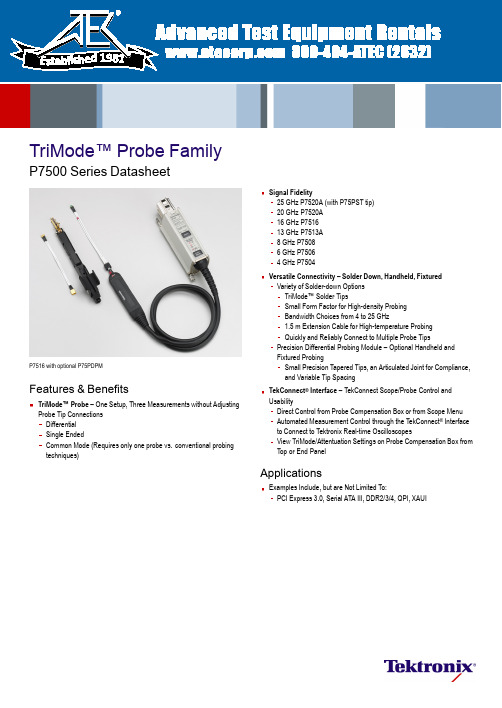
TriMode™Probe FamilyP7500SeriesDatasheetP7516with optional P75PDPMFeatures &Bene fitsTriMode™Probe –One Setup,Three Measurements without Adjusting Probe Tip Connections Differential Single EndedCommon Mode (Requires only one probe vs.conventional probing techniques)Signal Fidelity25GHz P7520A (with P75PST tip)20GHz P7520A 16GHz P751613GHz P7513A 8GHz P75086GHz P75064GHz P7504Versatile Connectivity –Solder Down,Handheld,Fixtured Variety of Solder-down Options TriMode™Solder TipsSmall Form Factor for High-density Probing Bandwidth Choices from 4to 25GHz1.5m Extension Cable for High-temperature Probing Quickly and Reliably Connect to Multiple Probe TipsPrecision Differential Probing Module –Optional Handheld and Fixtured ProbingSmall Precision Tapered Tips,an Articulated Joint for Compliance,and Variable Tip Spacing TekConnect ®Interface –TekConnect Scope/Probe Control and UsabilityDirect Control from Probe Compensation Box or from Scope Menu Automated Measurement Control through the TekConnect ®Interface to Connect to Tektronix Real-time OscilloscopesView TriMode/Attentuation Settings on Probe Compensation Box from Top or End PanelApplicationsExamples Include,but are Not Limited To:PCI Express 3.0,Serial ATA III,DDR2/3/4,QPI,XAUI1981DatasheetBefore TriMode:1Probe for Differential;2Probes for SE and Common Mode;or 1Probe Soldered and Resoldered 3times;2Probes for Common Mode.TriMode™Probing,Connectivity,and PerformanceTriMode™Probing ArchitectureOne-probe setup makes differential,single ended,and common mode measurements accurately and de finitively.Tektronix is a known leader when it comes to signal fidelity and signalacquisition.Building on our history of market-leading innovations inprobing,After TriMode (P75TLRST):1Probe for Differential,Single Ended,and Common Mode,with only 1setup required.we invented a revolutionary probing architecture called “TriMode™Probing”that de fines the next-generation industry benchmark for usability and signal fidelity.This architecture changes the rules of probing and allows you to work more effectively and ef ficiently.By enabling unique functionality,the P7500Series TriMode probes allow you to switch between differential,single ended,and common mode measurements without moving the probe from its connection points.Improved productivity is achieved by reducing setup time.One setup can be used to make the three different types of measurements all with the press of a button.The TriMode Probe architecture for the P7500Series probes continues the Tektronix tradition of high-bandwidth and low-DUT loading while providing improved connectivity and value.2TriMode™Probe Family —P7500SeriesConnectivity Plus –Solder Down –Handheld –FixturedThe P7500Series TriMode probe architecture offers various levels of connectivity and provides the highest probe fidelity available for real-time oscilloscopes.The multipoint connectivity solutions of the P7500Series include:TriMode Performance Solder Tip The highest-performance solder tip.Up to 25GHzbandwidth.TriMode Long-reach Solder Tip A high performance solder tip with a long reach and very small,low-pro file form factor.Up to 20GHzbandwidth.TriMode Resistor Solder Tip High-performance solder tip with easy-to-solder tip resistors.Up to 18GHzbandwidth.TriMode Extended-resistor Solder Tip Medium-performance solder tip with long easy-to-solder tip resistors.Up to 7GHzbandwidth.3DatasheetTriMode Micro-coax Tip Low-cost,quick-connect solder tips.Up to 4GHzbandwidth.TriMode High-temperature Tip When used with the 1.5m Socket Cable XL,this tip can be used in environments from –55°C to 150°C.Up to 10GHz bandwidth withDSP.Damped Wire Tip Low-cost solder tips ideal for high-density probing.Up to 8GHzbandwidth.Precision Differential Probing Module High-performance handheld probing module.Up to 18GHzbandwidth.Handheld and fixtured probing needs are met using the optional Precision Differential Probing Module (P75PDPM).Its small precision tapered tips,variable articulation of the probe tip,and quick-adjusting variable tip spacing provides the needed flexibility for adapting to vias and other test points of differing sizes from 30mils to 180mils.These precision connectivity tools enable you to access multiple signals on anything from convenient test pads to hard-to-reach,high-density circuitry.4TriMode™Probe Family —P7500SeriesSignal FidelityYou can be con fident in the signal fidelity of your measurements.The innovative new Tektronix differential architecture,coupled with the superior electrical performance of IBM SiGe Technology,provides the bandwidth and fidelity to meet the industry needs of today as well as tomorrow.The P7500Series Probe Architecture provides:Highest bandwidth available –25GHz Excellent step response Low-DUT loading High CMRRDifferential,single ended,or common mode measurements using one probePerformance You Can Count OnDepend on Tektronix to provide you with performance you can count on.In addition to industry-leading service and support,this product comes backed by a one-year warranty as standard.CharacteristicsP7500with P75PDPMTriMode Probe ArchitectureP7520AP7516P7513A P7508P7506P7504Bandwidth (Typical,Probe Only)>20GHz,A-B mode >18GHz,P75PDM,other modes >16GHz >13GHz >8GHz >6GHz >4GHz Rise Time (10-90%)(Typical,Probe Only)<27ps,A-B mode <29ps,other modes <32ps <40ps <55ps <75ps <105ps Rise Time (20-80%)(Typical,Probe Only)<18ps,A-B mode <20ps,other modes<24ps <28ps <35ps <50ps <70ps Attenuation(User Selectable)5X or 12.5X 5X or 12.5X 5X or 12.5X 5X or 12.5X 5X or 12.5X 5X or 12.5X Differential Input Range ±0.625V (5X)±1.6V (12.5X)±0.75V (5X)±1.75V (12.5X)±0.75V (5X)±1.75V (12.5X)±0.75V (5X)±1.75V (12.5X)±0.75V (5X)±1.75V (12.5X)±0.75V (5X)±1.75V (12.5X)Operating Voltage Window+3.7to –2.0V +4.0to –2.0V +4.0to –2.0V +4.0to –2.0V +4.0to –2.0V +4.0to –2.0V Offset Voltage Range+2.5to –1.5V,A-B mode +3.4to –1.8V,other modes +2.5to –1.5V,A-B mode +3.4to –1.8V,other modes +2.5to –1.5V,A-B mode +3.4to –1.8V,other modes +2.5to –1.5V,A-B mode +3.4to –1.8V,other modes +2.5to –1.5V,A-B mode +3.4to –1.8V,other modes +2.5to –1.5V,A-B mode +3.4to –1.8V,other modes DC Input Resistance (Differential)100k ohms 100k ohms 100k ohms 100k ohms 100k ohms 100k ohms Noise<33nV /√Hz (5X)<48nV /√Hz (12.5X)<33nV /√Hz (5X)<48nV /√Hz (12.5X)<33nV /√Hz (5X)<48nV /√Hz (12.5X)<33nV /√Hz (5X)<48nV /√Hz (12.5X)<33nV /√Hz (5X)<48nV /√Hz (12.5X)<33nV /√Hz (5X)<48nV /√Hz (12.5X)CMRR(Differential Mode)>60dB at DC >40dB at 50MHz >30dB at 1GHz >20dB at 10GHz >12dB at 20GHz>60dB at DC >40dB at 50MHz >30dB to 1GHz >20dB to 8GHz >15dB to 16GHz>60dB at DC >40dB at 50MHz >30dB to 1GHz >20dB to 7GHz >15dB to 13GHz>60dB at DC >40dB at 50MHz >30dB at 1GHz >25dB at 4GHz >20dB at 8GHz>60dB at DC >40dB at 50MHz >30dB at 1GHz >25dB at 3GHz >20dB at 6GHz>60dB at DC >40dB at 50MHz >30dB at 1GHz >28dB at 2GHz >25dB at 4GHzNondestructive Input Range ±15V ±15V ±15V ±15V ±15V ±15V Interface TekConnect™TekConnect™TekConnect™TekConnect™TekConnect™TekConnect™Cable Length1meter1meter1.3meters1.3meters1.3meters1.3metersFor additional characteristics,refer to the individual probe Technical Reference Manuals.5DatasheetTypical System Speci ficationsThe typical system speci fications in the table below are achieved using a P7520A probe with a DPO/DSA72504D or DPO/DSA73304D Oscilloscope and a P75PST solder tip.CharacteristicA-B ModeAll Other ModesSystem Bandwidth25GHz >18GHz System Rise Time (10%–90%)<20ps <29ps System Rise Time (20%–80%)<14ps<20psMinimum System Requirements /Instrument CompatibilityP7500Series TriMode Differential Probes are compatible with the DPO/DSA/MSO70000and TDS6000B/C Series TekConnect Oscilloscopes.The chart below shows recommended probe/oscilloscope model combinations.InstrumentBW (Scope)FW VersionRecommended ProbeDPO/DSA73304D 33GHz V6.4.1or higher P7520A DPO/DSA72504D 25GHz V6.4.1or higher P7520A DPO/DSA7200420GHz V3.0or higher P7520A DPO/DSA7160416GHz V3.0or higher P7516DPO/DSA7125412.5GHz V3.0or higher P7513A DPO/DSA708048GHz V3.0or higher P7508DPO/DSA706046GHz V3.0or higher P7506DPO/DSA704044GHzV3.0or higher P7504TDS6000C 12.5GHz,15GHz V5.1.7P7516,P7513A TDS6000B8GHz,6GHzV5.1.3P7508,P750680A03TekConnect Probe Interface V2.3All P7500Series probes RTPA2A TekConnect Probe InterfaceV2.3All P7500Series probesOrdering InformationP7520A TriMode™Differential Probe,20GHz,for TekConnect Interface Oscilloscopes.P7516TriMode™Differential Probe,16GHz,for TekConnect Interface Oscilloscopes.P7513A TriMode™Differential Probe,13GHz,for TekConnect Interface Oscilloscopes.P7508TriMode™Differential Probe,8GHz,for TekConnect Interface Oscilloscopes.P7506TriMode™Differential Probe,6GHz,for TekConnect Interface Oscilloscopes.P7504TriMode™Differential Probe,4GHz,for TekConnect Interface Oscilloscopes.All Include :One-year warranty,plus see Standard Accessories table.Service OptionsOptionDescriptonCA1Single Calibration or Functional Veri fication C3Calibration Service 3Years C5Calibration Service 5YearsD3Calibration Data Report 3Years (with Option C3)D5Calibration Data Report 5Years (with Option C5)G3Complete Care 3Years (includes loaner,scheduled calibration and more)G5Complete Care 5Years (includes loaner,scheduled calibration and more)R3Repair Service 3Years R5Repair Service 5YearsAdditional Service Products Available During Warranty (DW)R3PDW Repair service coverage 3years (includes product warranty period).3-year period starts at time of customer instrument purchaseR5PDWRepair service coverage 5years (includes product warranty period).5-year period starts at time of customer instrument purchase6TriMode™Probe Family —P7500SeriesStandard AccessoriesDescriptionP7520A/P7516P7513A/P7508P7506/P7504Reorder Part Number020-2790-xx(P7516/P7513A/P7508)020-2977-xx (P7506/P7504)The documentation kit contains:Printed Quick Start User Manuals,CD-ROM contains PDFs of basic probe and measurement literature,and the probe manuals (Quick Start User Manual and Technical Reference Manual)1each *11each 1each071-3048-xx (P7520A)Antistatic Wrist Strap1each 006-3415-xx Certi ficate of Traceable Calibration1each 1each 1each Standard with probe Data Calibration Report:Lists themanufacturing test results of your probe at the time of shipment and is included with every probe1each 1each 1eachStandard with probeDC Probe Calibration Fixture1each 067-1821-xx DC Probe Calibration Fixture1each 1each 067-1967-xx 50ΩCoax Cable –Male BNC to Male BNC1each 1each 1each 012-0208-xx 50ΩCoax Cable –Male SMA to Male SMA1each 1each 1each174-1120-xx Solder Tip Ramps (25each)1each (P7520A only)020-3118-xx P7520A/P7516/P7513A/P7508Accessory Box (See contents listing below 1through 7)1)TriMode Long-reach Solder Tip2each 2eachP75TLRST 2)G3PO Bullet Kit (includes 4bullets)1each 013-0359-xx 3)G3PO Bullet Removal Tool1each 003-1896-xx 4)Solder Kit:Solder Spool,Wire Spool1each 1each 020-2754-xx 5)Tape,Adhesive (Strip,10each)1each 1each 006-8237-xx 6)Marker Band Set (2each of 5colors)1each 1each 016-0633-xx 7)Socket Cable1each020-2954-xxP7506/P7504Accessory Box (See contents listing below 1through 6)1)Socket Cable1each 020-2954-xx 2)TriMode Micro-coax Tip4each 020-2955-xx 3)TriMode High-temperature Tip2each 020-2958-xx 4)Solder Kit:Solder Spool,Wire Spool 1each 020-2754-xx 5)Tape,Adhesive (Strip,10each)1each 006-8237-xx 6)Marker Band Set (2each of 5colors)1each016-0633-xx*1P7520A documentation is a printed instruction manual.7DatasheetContact Tektronix:ASEAN /Australasia (65)63563900Austria 0080022554835*Balkans,Israel,South Africa and other ISE Countries +41526753777Belgium 0080022554835*Brazil +55(11)37597627Canada 180********Central East Europe and the Baltics +41526753777Central Europe &Greece +41526753777Denmark +4580881401Finland +41526753777France 0080022554835*Germany 0080022554835*Hong Kong 4008205835India 0008006501835Italy 0080022554835*Japan 81(3)67143010Luxembourg +41526753777Mexico,Central/South America &Caribbean 52(55)56045090Middle East,Asia,and North Africa +41526753777The Netherlands 0080022554835*Norway 80016098People’s Republic of China 4008205835Poland +41526753777Portugal 800812370Republic of Korea 00180082552835Russia &CIS +7(495)7484900South Africa +41526753777Spain 0080022554835*Sweden 0080022554835*Switzerland 0080022554835*Taiwan 886(2)27229622United Kingdom &Ireland 0080022554835*USA 180*********European toll-free number.If not accessible,call:+41526753777Updated 10February 2011For Further Information.Tektronix maintains a comprehensive,constantly expanding collection of application notes,technical briefs and other resources to help engineers working on the cutting edge of technology.Please visit Copyright ©Tektronix,Inc.All rights reserved.Tektronix products are covered by U.S.and foreign patents,issued and rmation in this publication supersedes that in all previously published material.Speci fication and price change privileges reserved.TEKTRONIX and TEK are registered trademarks of Tektronix,Inc.All other trade names referenced are the service marks,trademarks,or registered trademarks of their respective companies.17Aug 201251W-20271-13Optional Tip AccessoriesDescriptionPart NumberTriMode Performance Solder TipP75PST P7500Series Precision Differential Probing ModuleP7500Precision Differential Probing Module Accessory Kit (See 1through 7below)P75PDPM 1)Tip Cable (1ps matched pair,1each)P75TC 2)Probing Module TipProbe Tips Replacement Kit 1Each (Right and left side)P75PMT 3)Accessory Kit;Ground Spring,Large 4Each 016-1998-xx 4)Accessory Kit;Ground Spring,Small 4Each 016-1999-xx 5)Handle,Adapter (Probing Module)367-0545-xx 6)G3PO Separator Tool 003-1897-xx 7)Ground Spring Tool 003-1900-xx TriMode Resistor Solder Tip020-2936-xx TriMode Extended-resistor Solder Tip 020-2944-xx Resistor Replacement Kit 020-2937-xx Solder Tip Ramps,25Each 020-3118-xx Socket Cable 020-2954-xx Socket Cable,XL020-2960-xx TriMode High-temperature Tip 020-2958-xx TriMode Micro-coax Tip 020-2955-xx Damped Wire Tip020-2959-xx Nexus Interposer DDR Solder Tip 020-3022-xx Deskew Fixture 067-1586-xx Probe PositionerPPM100Precision,3Position,Probe Positioner PPM203B 8200Series TekConnect ®Probe Interface 80A03(FW Version ≥2.3)RTSA Series TekConnect ®Probe InterfaceRTPA2A(FW Version ≥2.3)Tektronix is registered to ISO 9001and ISO 14001by SRI Quality SystemRegistrar.Product(s)complies with IEEE Standard 488.1-1987,RS-232-C,and with Tektronix Standard Codes and Formats.。
- 1、下载文档前请自行甄别文档内容的完整性,平台不提供额外的编辑、内容补充、找答案等附加服务。
- 2、"仅部分预览"的文档,不可在线预览部分如存在完整性等问题,可反馈申请退款(可完整预览的文档不适用该条件!)。
- 3、如文档侵犯您的权益,请联系客服反馈,我们会尽快为您处理(人工客服工作时间:9:00-18:30)。
元器件交易网Data Sheet PT7C4363 Real-time Clock Module (I2C Bus) DescriptionThe PT7C4363 serial real-time clock is a low-power clock/calendar with a programmable square-wave output.|||||||||||||||||||||||||||||||||||||||||||||||||||||||||||||||||||||||||||||||||||||||||||||||||||||||||||||||||||||||||||||||||||||||||||||||||||||||||||||||||||||||||||||||||||||||||||||||||||||||||||||||||||||||||||||||||||||||||||||||||||||||||||||||||||||||||||||||||||||||||||||||||||||||||||||||||||||||||||||||||||||||Features• • • Using external 32.768kHz quartz crystal Supports I2C-Bus's high speed mode (400 kHz) Includes time (Hour/Minute/Second) and calendar (Year/Month/Date/Day) counter functions (BCD code) • • • • Programmable square wave output signal Oscillator stop flag Low backup current: typ. 500nA at VDD=3.0V and TA=25°C Operating range: 1.8V to 5.5VAddress and data are transferred serially via a 2-wire bidirectional bus. The clock/calendar provides seconds, minutes, hours, day, date, month, and year information. The date at the end of the month is automatically adjusted for months with fewer than 31 days, including corrections for leap year. The clock operates in the 24hour format indicator. Table 1 shows the basic functions of PT7C4363. MoreOrdering InformationPart Number PT7C4363P PT7C4363W Package 8-Pin DIP 8-Pin SOICdetails are shown in section: overview of functions.Note: Lead free package is available by adding “E” after each part number. For example: PT7C4363PE. Table 1. Basic functions of PT7C4363 Item Function Source: Crystal: 32.768kHz 1 Oscillator Oscillator enable/disable Oscillator fail detect Time display 2 Time Century bit Time count chain enable/disable 3 4 5 Interrupt Alarm interrupt Timer interrupt output 2-wire I2C bus 3-wire bus Burst mode Write protection External clock test mode Power-on reset override 12-hour 24-hourPT7C4363 √ √ √ √ √ √ √ 1, 32, 1.024k, 32.768k √ √ √Programmable square wave output (Hz) Communicat ion6ControlPT0207(07/05) 1Ver: 0元器件交易网Data Sheet PT7C4363 Real-time Clock Module (I2C Bus)|||||||||||||||||||||||||||||||||||||||||||||||||||||||||||||||||||||||||||||||||||||||||||||||||||||||||||||||||||||||||||||||||||||||||||||||||||||||||||||||||||||||||||||||||||||||||||||||||||||||||||||||||||||||||||||||||||||||||||||||||||||||||||||||||||||||||||||||||||||||||||||||||||||||||||||||||||||||||||||||||||||||Function BlockPT7C4363X132.768 kHzCDComparatorAlarm Register(Min, Hour, Day, Date)OSCCounter ChainTimerTime Counter(Sec,Min,Hour,Day,Date,Month,Year)X2CGControl RegisterAddress DecoderAddress Register I /O Interface (I2C) Shift RegisterSCLINT SQWTimer / Alarm Interrupt Control Square Wave Output ControlSDANote: PT7C4363 need to add a 10pF ~ 30pF capacitor between X1 and GND to get the accurate 32k frequency.Recommended Layout for CrystalPT7C4363 PT7C4307X132.768kHz CrystalX2Local Ground plane Layer 2 Guard Ring (connect to gound)Crystal SpecificationsParameter Nominal Frequency Series Resistance Load Capacitance Symbol fO ESR CL Min Typ 32.768 10 Max 40 Unit kHz kΩ pFThe crystal, traces and crystal input pins should be isolated from RF generating signals.PT0207(07/05) 2Ver: 0元器件交易网Data Sheet PT7C4363 Real-time Clock Module (I2C Bus)|||||||||||||||||||||||||||||||||||||||||||||||||||||||||||||||||||||||||||||||||||||||||||||||||||||||||||||||||||||||||||||||||||||||||||||||||||||||||||||||||||||||||||||||||||||||||||||||||||||||||||||||||||||||||||||||||||||||||||||||||||||||||||||||||||||||||||||||||||||||||||||||||||||||||||||||||||||||||||||||||||||||Pin ConfigurationPT7C43631X1VCC82X2 INTSQW 7 SCL634GNDSDA5DIP-8 SOIC-8Pin DescriptionPin no. 1 Pin X1 Type I Description Oscillator Circuit Input. Together with X2, 32.768kHz crystal is connected between them.2X2OOscillator Circuit Output. Together with X1, 32.768kHz crystal is connected between them.3INTOInterrupt Output. Open drain, active low.4GNDPGround. Serial Data Input/Output. SDA is the input/output pin for the 2-wire serial interface. The SDA pin is open-drain output and requires an external pull-up resistor. Serial Clock Input. SCL is used to synchronize data movement on the I2C serial interface. Clock Output. Open drain. Four frequencies selectable: 32.768k, 1.024k, 32, 1Hz when SQWE bit is set to 1. Power.5 6 7SDA SCL SQWI/O I O8VCCPPT0207(07/05) 3Ver: 0元器件交易网Data Sheet PT7C4363 Real-time Clock Module (I2C Bus)|||||||||||||||||||||||||||||||||||||||||||||||||||||||||||||||||||||||||||||||||||||||||||||||||||||||||||||||||||||||||||||||||||||||||||||||||||||||||||||||||||||||||||||||||||||||||||||||||||||||||||||||||||||||||||||||||||||||||||||||||||||||||||||||||||||||||||||||||||||||||||||||||||||||||||||||||||||||||||||||||||||||Function DescriptionOverview of Functions1.Clock functionCPU can read or write data including the year (last two digits), month, date, day, hour, minute, and second. Any (two-digit) year that is a multiple of 4 is treated as a leap year and calculated automatically as such until the year 2100.2.Alarm functionThese devices have one alarm system that outputs interrupt signals from INTA for PT7C4363 or INT/OUT/SQW for PT7C4341 to CPU when the date, day of the week, hour, minute or second correspond to the setting. Each of them may output interrupt signal separately at a specified time. The alarm may be selectable between on and off for matching alarm or repeating alarm.3.Programmable square wave outputA square wave output enable bit controls square wave output at pin 7. 4 frequencies are selectable: 1, 32, 1.024k, 32.768k Hz.4.Interface with CPUData is read and written via the I2C bus interface using two signal lines: SCL (clock) and SDA (data). Since the output of the I/O pin SDA is open drain, a pull-up resistor should be used on the circuit board if the CPU output I/O is also open drain. The SCL's maximum clock frequency is 400 kHz, which supports the I2C bus's high-speed mode.5.Oscillator fail detectWhen oscillator fail, OSF bit will be set.6.Oscillator enable/disableOnly time count chain can be enable or disable by STOP bit..7.Timer functionThe timer control register determines one of 4 source clock frequencies for the timer (4096 Hz, 64 Hz, 1 Hz, or 1/60 Hz) and enables or disables the timer. The timer counts down from software loaded 8-bit binary value. At the end of every countdown, the timer sets the Timer Flag (TF). The TF may only be cleared by software. The asserted TF can be used to generate an interrupt. The interrupt may be generated as a pulsed signal every countdown period or as a permanently active signal which follows the condition of TF. Bit TI/TP is used to control this mode selection. When reading the timer, the current countdown value is returned.8.Reset functionThe PT7C4363 includes an internal reset circuit which is active whenever the oscillator is stopped. In the reset state the I2C-bus logic is initialized and all registers, including the address pointer, are cleared with the exception of bits FE, OSF, TD1, TD0, TESTC and AE which are set to logic 1.PT0207(07/05) 4Ver: 0元器件交易网Data Sheet PT7C4363 Real-time Clock Module (I2C Bus)|||||||||||||||||||||||||||||||||||||||||||||||||||||||||||||||||||||||||||||||||||||||||||||||||||||||||||||||||||||||||||||||||||||||||||||||||||||||||||||||||||||||||||||||||||||||||||||||||||||||||||||||||||||||||||||||||||||||||||||||||||||||||||||||||||||||||||||||||||||||||||||||||||||||||||||||||||||||||||||||||||||||Registers1. Allocation of registers Function (time range BCD format) Control/status 1 Control/status 2 Seconds (00-59) Minutes (00-59) Hours (00-23) Dates (01-31) Days of the week (00-06) Months (01-12) Years (00-99) Alarm: Minutes (00-59) Alarm: Hours (01-12) Alarm: Dates (01-31) Alarm: Weekday (00-06) SQW control Timer control Timer Register definition Bit 7 TEST1*2Addr. (hex) *1 00 01 02 03 04 05 06 07 08 09 0A 0B 0C 0D 0E 0FBit 6 S40 M40 × × × × Y40 M40 × × × × ×Bit 5 STOP*3 S20 M20 H20 D20 × × Y20 M20 H20 D20 × × ×Bit 4 TI/TP*5 S10 M10 H10 D10 × MO10 Y10 M10 H10 D10 × × ×Bit 3 TESTC*4 AF*6 S8 M8 H8 D8 × MO8 Y8 M8 H8 D8 × × ×Bit 2 TF*6 S4 M4 H4 D4 W4 MO4 Y4 M4 H4 D4 W4 × ×Bit 1 AIE*7 S2 M2 H2 D2 W2 MO2 Y2 M2 H2 D2 W2 RS1 TD1*11Bit 0 TIE*7 S1 M1 H1 D1 W1 MO1 Y1 M1 H1 D1 W1 RS0 TD0*11OSF*8 × × × × Century Y80 AE*9 AE*9 AE*9 AE*9 SQWE TE*10Timer count down valueCaution points: *1. PT7C4363 uses 8 bits for address. For excess 0FH address, PT7C4363 will not respond. *2. EXT_CLK test mode select bit. *3. When the bit is logic 1, time count chain stops but oscillator still runs. *4. Power-on reset override enable bit. *5. Timer interrupt output select bit. *6. Alarm and timer interrupt flag bits. *7. Alarm and timer interrupt enable bits. *8. Oscillator fail indicates. Indicate clock integrity. *9. Alarm enable bit. Alarm will be active when related time is matching if AE = 0. *10. Timer enable bit. *11. Timer source clock frequency select. *12. All bits marked with "×" are not implemented. All bits marked with "-" are not used bits and should always be written with logic 0. If read them, they could be logic 0 or 1.PT0207(07/05) 5Ver: 0元器件交易网Data Sheet PT7C4363 Real-time Clock Module (I2C Bus)|||||||||||||||||||||||||||||||||||||||||||||||||||||||||||||||||||||||||||||||||||||||||||||||||||||||||||||||||||||||||||||||||||||||||||||||||||||||||||||||||||||||||||||||||||||||||||||||||||||||||||||||||||||||||||||||||||||||||||||||||||||||||||||||||||||||||||||||||||||||||||||||||||||||||||||||||||||||||||||||||||||||2.Control and status registerAddr. (hex) 00 01 0D 0E 0FDescription Control/status 1 (default) Control/status 2 (default) SQW control (default) Timer control (default) Timer (default)D7 TEST1 0D6 UndefinedD5 STOP 0D4 Undefined TI/TP 0D3 TESTC 1D2D1D0Undefined Undefined Undefined AIE 0 RS1 0 TD1 1 TIE 0 RS0 0 TD0 1Undefined Undefined Undefined SQWE 1 TE 0AF TF Undefined Undefined× × × × × Undefined Undefined Undefined Undefined Undefined × × × × × Undefined Undefined Undefined Undefined Undefined Timer count down value Undefineda) •Timer TE: Timer Enable bit. TE Data 0 Read / Write 1 Timer enabled Timer disabledDescription Default•TD1, TD0: timer source clock frequency select. These bits determine the source clock for the countdown timer. TD1, TD0 Data Timer source clock freq. (Hz) 00 01 Read / Write 10 11 1 1/60 When not in use, TD1 TD0 should be set to 11 for power saving. 4.096k 64•Timer: Timer Read / WriteData 00~FF Count down value (n)Description Countdown Period = n / Source Clock FrequencyFor example: If TE = 1, TD1 TD0 = 10, Timer = 03 are written into PT7C4363, timer counts down every 1 second from 03 to 01 then 03 cycled.PT0207(07/05) 6Ver: 0元器件交易网Data Sheet PT7C4363 Real-time Clock Module (I2C Bus)|||||||||||||||||||||||||||||||||||||||||||||||||||||||||||||||||||||||||||||||||||||||||||||||||||||||||||||||||||||||||||||||||||||||||||||||||||||||||||||||||||||||||||||||||||||||||||||||||||||||||||||||||||||||||||||||||||||||||||||||||||||||||||||||||||||||||||||||||||||||||||||||||||||||||||||||||||||||||||||||||||||||b) •Timer Interrupt TIE: Timer Interrupt Enable bit. TIE Data 0 Read / Write 1 Timer interrupt enabled Timer interrupt disabledDescription Default•TF: Timer Flag TF Read WriteData 0 1 0 1 Timer flag inactiveDescription Timer flag active. At the end of a timer countdown, TF is set to 1. Timer flag is cleared Timer flag remains unchanged•TI/TP: Timer Interrupt output select TI/TP Data 0DescriptionINT is active when TF is active (subject to the status of TIE) INT pulses active according to source clock frequency and timer count down value (subject to the status of TIE).Read / Write 1Source clock (Hz) 4096 64 1 1/60INT negative pulse width (s) n=1 n>1 1 1 /8192 /4096 1 1 /128 /64 1 1 /64 /64 1 1 /64 /64Note: TF and INT become active simultaneously. n = loaded countdown value. Timer stopped when n = 0.Example 1: If TE = 1, TD1 TD0 = 00, Timer = 03, TIE = 1, TF = 0, TI/TP = 1 are written into PT7C4363, timer register counts down every 1/4.096kHz seconds from 03 to 01 then 03 cycled and INT output negative pulse with 1/4096 seconds width. See Fig.1.4.096kHz internal clockTimer=02 Timer=01 Timer=03 Timer=02 Timer=01 Timer=03Set TF=1INTFig.1 Example 1 of timer interruptsPT0207(07/05) 7Ver: 0元器件交易网Data Sheet PT7C4363 Real-time Clock Module (I2C Bus)|||||||||||||||||||||||||||||||||||||||||||||||||||||||||||||||||||||||||||||||||||||||||||||||||||||||||||||||||||||||||||||||||||||||||||||||||||||||||||||||||||||||||||||||||||||||||||||||||||||||||||||||||||||||||||||||||||||||||||||||||||||||||||||||||||||||||||||||||||||||||||||||||||||||||||||||||||||||||||||||||||||||Example 2: If TE = 1, TD1 TD0 = 10, Timer = 03, TIE = 1, TF = 0, TI/TP = 1 are written into PT7C4363, timer counts down every 1/4.096kHz seconds from 03 to 01 then 03 cycled and INT output negative pulse with 1/64 seconds width. See Fig.2.1Hz internal clockTimer=02 Timer=01 Timer=03 Timer=021/64INTSet TF=1Fig.2 Example 2 of timer interrupts c) • Alarm Interrupt AIE: Alarm Interrupt Enable bit. AIE Data 0 Read / Write 1 • AF: Alarm Flag AF Read Write Alarm interrupt enabled Alarm interrupt disabledDescription DefaultData 0 1 0 1 Alarm flag inactive Alarm flag active Alarm flag is cleared Alarm flag remains unchangedDescriptiond) •SQW control SQWE: SQW output clock enable bit. SQWE Data 0 Read / Write 1 the SQW output is activatedDescriptionthe SQW output is inhibited and SQW output is set to high-impedance Default•RS1, RS0: SQW output frequency select. RS1, RS0 Data 00 01 Read / Write 10 11 32 1 32.768k 1.024kSQW output freq. (Hz) DefaultPT0207(07/05) 8Ver: 0元器件交易网Data Sheet PT7C4363 Real-time Clock Module (I2C Bus)|||||||||||||||||||||||||||||||||||||||||||||||||||||||||||||||||||||||||||||||||||||||||||||||||||||||||||||||||||||||||||||||||||||||||||||||||||||||||||||||||||||||||||||||||||||||||||||||||||||||||||||||||||||||||||||||||||||||||||||||||||||||||||||||||||||||||||||||||||||||||||||||||||||||||||||||||||||||||||||||||||||||e) •Time count STOP STOPData 0 RTC source clock runs.Description DefaultRead / Write 1All RTC divider chain flip-flops are asynchronously set to logic 0; the RTC clock is stopped (SQW at 32.768 kHz is still available)f) •Test TEST1 TEST1 Read / Write 1 EXT_CLK test mode.Data 0 Normal mode.Description Default•TESTC TESTC Read / WriteData 0 1Description Power-on reset override facility is disabled; set to logic 0 for normal operation. Power-on reset override may be enabled Default3.Time CounterTime digit display (in BCD code): • Second digits: Range from 00 to 59 and carried to minute digits when incremented from 59 to 00. • Minute digits: Range from 00 to 59 and carried to hour digits when incremented from 59 to 00. • Hour digits: See description on the /12, 24 bit. Carried to day and day-of-the-week digits when incremented from 11 p.m. to 12 a.m. or 23 to 00. Addr. (hex) 02 03 04 Description Seconds (default) Minutes (default) Hours (default) D7 OSF*1 1 × 0 × 0 D6 D5 D4 D3 D2 D1 D0S40 S20 S10 S8 S4 S2 S1 Undefined Undefined Undefined Undefined Undefined Undefined Undefined M40 M20 M10 M8 M4 M2 M1 Undefined Undefined Undefined Undefined Undefined Undefined Undefined × 0 H20 H10 H8 H4 H2 H1 Undefined Undefined Undefined Undefined Undefined Undefined*1 Note: Indicate clock integrity. When the bit is 1, the clock integrity is no longer guaranteed and the time need be adjusted.PT0207(07/05) 9Ver: 0元器件交易网Data Sheet PT7C4363 Real-time Clock Module (I2C Bus)|||||||||||||||||||||||||||||||||||||||||||||||||||||||||||||||||||||||||||||||||||||||||||||||||||||||||||||||||||||||||||||||||||||||||||||||||||||||||||||||||||||||||||||||||||||||||||||||||||||||||||||||||||||||||||||||||||||||||||||||||||||||||||||||||||||||||||||||||||||||||||||||||||||||||||||||||||||||||||||||||||||||4. Days of the week Counter The day counter is a divide-by-7 counter that counts from 00 to 06 and up 06 before starting again from 00. Values that correspond to the day of week are user defined but must be sequential (i.e., if 0 equals Sunday, then 1 equals Monday, and so on). Illogical time and date entries result in undefined operation. Addr. (hex) 06 Description Days of the week (default) Calendar Counter D7 × 0 D6 × 0 D5 × 0 D4 × 0 D3 × 0 D2 D1 D0W4 W2 W1 Undefined Undefined Undefined5.The data format is BCD format. • Day digits: Range from 1 to 31 (for January, March, May, July, August, October and December). Range from 1 to 30 (for April, June, September and November). Range from 1 to 29 (for February in leap years). Range from 1 to 28 (for February in ordinary years). Carried to month digits when cycled to 1. • Month digits: Range from 1 to 12 and carried to year digits when cycled to 1. • Year digits: Range from 00 to 99 and 00, 04, 08, … , 92 and 96 are counted as leap years. Addr. (hex) 05 07 08Description Dates (default) Months (default) Years (default)D7 × 0 Century*1 UndefinedD6 × 0 × 0D5D4D3D2D1D0D20 D10 D8 D4 D2 D1 Undefined Undefined Undefined Undefined Undefined Undefined × 0 M10 M8 M4 M2 M1 Undefined Undefined Undefined Undefined UndefinedY80 Y40 Y20 Y10 Y8 Y4 Y2 Y1 Undefined Undefined Undefined Undefined Undefined Undefined Undefined Undefined*1: The century bit is toggled when the years register overflows from 99 to 00. 6. Alarm Register PT7C4363: Alarm Register Addr. 09 0A 0B 0C Description Alarm: Minutes (default) Alarm: Hours (default) Alarm: Dates (default) Alarm: Weekday (default) D7*1D6D5 M20 Undefined H20 Undefined D20 Undefined × 0D4D3D2D1D0AE M40 Undefined Undefined AE*2 Undefined AE*3 Undefined AE*4 Undefined × 0 × 0 × 0M10 M8 M4 M2 M1 Undefined Undefined Undefined Undefined Undefined H10 H8 H4 H2 H1 Undefined Undefined Undefined Undefined Undefined D10 D8 D4 D2 D1 Undefined Undefined Undefined Undefined Undefined × 0 × 0 W4 W2 W1 Undefined Undefined Undefined*1 Note: Minute alarm enable bit. *2 Note: Hour alarm enable bit. *3 Note: Date alarm enable bit. *4 Note: Weekday alarm enable bit.PT0207(07/05) 10Ver: 0Alarm FunctionRelated registerRegister definitionFunctionBit 7 Bit 6 Bit 5 Bit 4 Bit 3 Bit 2 Bit 1 Bit 02 - - - TI/TP AF TF AIE TIE01 Control/status02 Seconds OSF S40 S20 S10 S8 S4 S2 S103 Minutes ×M40 M20 M10 M8 M4 M2 M104 Hours ××H20 H10 H8 H4 H2 H105 Dates ××D20 D10 D8 D4 D2 D106 Days of the week ×××××W4 W2 W1 09 Alarm: Minutes AE M40 M20 M10 M8 M4 M2 M10A Alarm:Hours AE ×H20 H10 H8 H4 H2 H1Dates AE ×D20 D10 D8 D4 D2 D1 0B Alarm:Weekday AE ××××W4 W2 W1 0C Alarm:When one or more of these registers are loaded with a valid minute, hour, day or weekday and its corresponding bit Alarm Enable (AE) is logic 0, then that information will be compared with the current minute, hour, day and weekday. When all enabled comparisons first match, the Alarm Flag (AF) is set. AF will remain set until cleared by software. Once AF has been cleared itwill only be set again when the time increments to match the alarm condition once more. Alarm registers which have their bit AEat logic 1 will be ignored.EXT_CLK Test Mode and POR override1.EXT_CLK Test ModeA test mode is available which allows for on-board testing. In such a mode it is possible to set up test conditions and control the operation of the RTC. The test mode is entered by setting bit TEST1 in control/status1 register. Then pin SQW becomes an input.The test mode replaces the internal 64 Hz signal with the signal applied to pin SQW. Every 64 positive edges applied to pin SQWwill then generate an increment of one second.The signal applied to pin SQW should have a minimum pulse width of 300 ns and a minimum period of 1000 ns. The internal 64Hz clock, now sourced from SQW, is divided down to 1 Hz by a 26 divide chain called a pre-scaler. The pre-scaler can be set intoa known state by using bit STOP. When bit STOP is set, the pre-scaler isreset to 0 (STOP must be cleared before the pre-scaler can operate again).From a STOP condition, the first 1 second increment will take place after 32 positive edges on SQW. Thereafter, every 64 positive edges will cause a 1 second increment.Remark: Entry into EXT_CLK test mode is not synchronized to the internal 64 Hz clock. When entering the test mode, no assumption as to the state of the pre-scaler can be made.Operation example:1. Set EXT_CLK test mode (control/status 1, bit TEST1 = 1)2. Set STOP (control/status 1, bit STOP = 1)3. Clear STOP (control/status 1, bit STOP = 0)4. Set time registers to desired value5. Apply 32 clock pulses to SQW6. Read time registers to see the first change7. Apply 64 clock pulses to SQW8. Read time registers to see the second change.Repeat 7 and 8 for additional increments.2.Power-On Reset (POR) overrideThe POR duration is directly related to the crystal oscillator start-up time. Due to the long start-up times experienced by these types of circuits, a mechanism has been built in to disable the POR and hence speed up on-board test of the device. The setting of this mode requires that the I2C-bus pins, SDA and SCL, be toggled in a specific order as shown in Fig 6.4.2. All timings are required minimums.Once the override mode has been entered, the device immediately stops being reset and normal operation may commence i.e. entry into the EXT_CLK test mode via I2C-bus access.The override mode may be cleared by writing a logic 0 to TESTC. TESTC must be set to logic 1 before re-entry into the override mode is possible. Setting TESTC to logic 0 during normal operation has no effect except to prevent from entering the POR override mode.Power up Override activeFig.3 POR override sequenceCommunication1.I2C Bus Interfacea)Overview of I2C-BUSThe I2C bus supports bi-directional communications via two signal lines: the SDA (data) line and SCL (clock) line. A combination of these two signals is used to transmit and receive communication start/stop signals, data signals, acknowledge signals, and so on. Both the SCL and SDA signals are held at high level whenever communications are not being performed. The starting and stopping of communications is controlled at the rising edge or falling edge of SDA while SCL is at high level. During data transfers, data changes that occur on the SDA line are performed while the SCL line is at low level, and on the receiving side the data is captured while the SCL line is at high level. In either case, the data is transferred via the SCL line at a rate of one bit per clock pulse. The I2C bus device does not include a chip select pin such as is found in ordinary logic devices. Instead of using a chip select pin, slave addresses are allocated to each device and the receiving device responds to communications only when its slave address matches the slave address in the received data.b)System ConfigurationAll ports connected to the I2C bus must be either open drain or open collector ports in order to enable AND connections to multiple devices.SCL and SDA are both connected to the VDD line via a pull-up resistance. Consequently, SCL and SDA are both held at high level when the bus is released (when communication is not being performed).c)Starting and Stopping I2C Bus CommunicationsFig.5Starting and stopping on I2C bus*Note with caution that if the SDA data is changed while the SCL line is at high level, it will be treated as a START, RESTART, or STOP condition.• Data acknowledge response (ACK signal)When transferring data, the receiver generates a confirmation response (ACK signal, low active) each time an 8-bit data segment is received. If there is no ACK signal from the receiver, it indicates that normal communication has not been established. (This does not include instances where the master device intentionally does not generate an ACK signal.)Immediately after the falling edge of the clock pulse corresponding to the 8th bit of data on the SCL line, the transmitter releases the SDA line and the receiver sets the SDA line to low (= acknowledge) level.After transmitting the ACK signal, if the Master remains the receiver for transfer of the next byte, the SDA is released at the falling edge of the clock corresponding to the 9th bit of data on the SCL line. Data transfer resumes when the Master becomes the transmitter.When the Master is the receiver, if the Master does not send an ACK signal in response to the last byte sent from the slave, that indicates to the transmitter that data transfer has ended. At that point, the transmitter continues to release the SDA and awaits a STOP condition from the Master.e) Slave AddressThe I 2C bus device does not include a chip select pin such as is found in ordinary logic devices. Instead of using a chip select pin, 1 0 1 0 0 0 12. I 2C Bus’s Basic Transfer FormatSCL from Master 1289SDA from transmitter(sending side)SDA from receiver(receiving side)Release SDA Low activeACK signala)Write via I2C busb)Read via I2C bus•Standard read•Simplified readNote:1.The above steps are an example of transfers of one or two bytes only. There is no limit to the number of bytes transferredduring actual communications.2.49H, 4AH are used as test mode address. Customer should not use the addresses.Maximum RatingsStorage Temperature.......................................................................................................................-65o Cto +150o CAmbient Temperature with Power Applied...........................................................................-40o Cto +85o CSupply Voltage to Ground Potential (Vcc to GND) ..........................................................-0.3V to +6.5VDC Input (All Other Inputs except Vcc & GND)................................................................-0.3V to (V cc+0.3V)DC Output Voltage (SDA, /INTA, /INTB pins)..................................................................-0.3V to +6.5VPower Dissipation............................................................................................................................320mW (Depend on package)Note:Stresses greater than those listed under MAXIMUM RATINGS may cause permanent damage to the device. This is a stress rating only and functional operation of the device at these or any other conditions above those indicated in the operational sections of this specification is not implied. Exposure to absolute maximum rating conditions for extended periods may affect reliability.Recommended Operating ConditionsUnitMaxTypeSymbol Description Minvoltage 1.8 - 5.5 V CC PowerV V IH Input high level 0.7 V CC- V CC+0.3V IL Input low level -0.3 - 0.3 V CCtemperature -40 - 85 ºC T A Operating。