Structural order in glassy water
专业英语

questions
How
do you distinguish steel from cast iron? How do you distinguish low alloy steel from high alloy steel?
1.1.1 Iron and Steel
The earth contains a large number of metals which are useful to man. One of the most important of these is iron. Modern industry needs considerable quantities of this metal, either in the form of iron or in the form of steel.
Mechanical Engineering materials
Organic polymer materials Inorganic non-metallic materials
plastic rubber Synthetic Fibers Traditional ceramics Special Ceramics Metal Matrix Composites
1.1.1 Iron and Steel
The ore becomes molten, and its oxides combine with carbon from the coke. The non-metallic constituents of the ore combine with the limestone to form a liquid slag. This floats on top of the molten iron, and passed out of the furnace through a tap. The metal which remains is pig iron.
唐诗英译鉴赏

Wild grasses spread over ancient plain; With spring and fall they come and go. Fire tries to burn them up in vain; They rise again when spring winds blow. Their fragrance overruns the way; Their green invades the ruined town. To see my friend go away, My sorrow grows like grass overgrown.
韩愈
新年都未有芳华, 二月初惊见草芽。 白雪却嫌春色晚, 故穿庭树作飞花。
Spring Snow
On vernal day no flowers were in bloom, alas!
In second moon I’m glad to see the budding grass.
But white snow dislikes the late coming vernal breeze,
My door off says to eastward going ships “Goodbye!”
枫桥夜泊
Mooring by Maple Bridge at Night
张继
The crows at moonset cry, streaking the frosty sky;
北京化工大学硕士学位论文碳纤维增...

(a)65℃(b)95"C
图3—24不同温度10%NaOH水溶液浸泡1680h后VE树脂浇注体表面的电镜照片Fig.3~24SEM photographs ofVE resin casts surfaces after immersion for1680h in
10%NaOH aqueous solution at different temperatures
14.Apicella A.Migliaresi C.Nicolais L.Iaccarino L Roccotelli S The water ageing of unsaturated polyester-based composites:influence of resin chemical structure 1983(04)
6.Somjai Kajorncheappunngam The effects of environmental aging on the durability of glass/epoxy composites 1999
7.Halpin J C Role of the matrix in fibrous composite structures 1983
12.Apicella A.Tessieri R.de Cataldis C Sorption modes of water in glassy epoxies 1985
13.Li Rong Bao.Albert F Yee.Charles Y C Lee Moisture absorption and hygrothermal aging in a bismaleimide resin[外文期刊] 2001(17)
(a)未浸泡
新牛津译林版高中英语必修三Unit2NaturalDisasters-ExtendedReding

A. In the order of time. B. With the change of places. C. With the development of feelings. D. All above.
庞贝,意大利西南部的一座古罗 马城市,位于那不勒斯海湾,在 公元79年维苏威火山爆发时,被 火山灰掩埋。在1748年被重新发
Pompeii
现之前,它就像从未存在过一样 消失了。
Introduction
No Image
Fast-reading
Match the main idea of each paragraph
Careful-reading Read para. 5 and answer the question.
Which one is not referred to about its remains unearthed? A. Fresh walls B. Rich patterns of its floor
c. A huge cloud shot from the peak of the volcano, looking like a
huge tree of fire.
d. The earth began to shake and the sound of falling roofs could
be heard. e. The earthquake came.
新牛津译林版高中英语必修三 Unit 2 Extended Reading The last days of pompeii
Lead-in
耐火材料用语词典英文

耐火材料用语词典英文耐火材料用语词典。
A B.Abrasive wear: The loss of material caused by friction between hard particles.Acid-resistant material: A material that can resist corrosion caused by acids.Aggregate: A mixture of coarse particles, such as sandor gravel, used in concrete or mortar.Alumina: A chemical compound with the formula Al2O3, used as a refractory material due to its high melting point.Alumina brick: A rectangular unit made from alumina-based refractory material, used in high-temperature applications.Alumina castable: A type of refractory material that can be cast or molded into shape, containing alumina as its main constituent.Alumina refractory: A type of refractory material that has a high alumina content, offering excellent resistance to thermal shock and corrosion.Annealing: A heat treatment process used to relieve internal stresses in a material, improving its mechanical properties.Bauxite: A naturally occurring mineral ore, primarily used as a source of alumina.Bond: The material used to bind refractory particles together, such as clays or cement.Bonded refractory: A type of refractory material that uses a bond to hold the particles together, rather than sintering.Brick: A rectangular unit made from refractory material, used in lining fireboxes, furnaces, and other high-temperature applications.C D.Casting: The process of pouring molten material into a mold to create a desired shape.Castable refractory: A type of refractory material that can be cast or poured into place, offering excellent adaptability and conformability.Cement: A binder used to hold particles together, typically made from limestone and clay.Corrosion: The degradation of a material caused by chemical reactions with its environment.Cracking: The formation of cracks in a material due to thermal stresses or mechanical loads.Dense refractory: A type of refractory material with a high density, offering excellent resistance to heat flux and wear.Ductility: The ability of a material to deform without fracturing under tensile stress.E F.Erosion: The gradual loss of material caused by wear, corrosion, or chemical attack.Expansion joint: A gap or joint designed to allow for thermal expansion and contraction of materials.Firebrick: A rectangular unit made from refractory material, used in high-temperature applications such as furnaces and fireboxes.Fireclay: A type of refractory material with a high silica content, used for high-temperature applications.Flame-resistant material: A material that can resistthe direct impact of flames without significant degradation.Fusion: The process of melting or fusing materials together, typically through the application of heat.Furnace: A device used to heat materials to high temperatures, typically for metallurgical or industrial processes.G H.Graphite: A carbon-based material with high thermal conductivity and resistance to high temperatures.Hardening: The process of increasing a material's hardness and strength through heat treatment or other means.Heat resistance: The ability of a material to withstand high temperatures without significant degradation.High-alumina refractory: A type of refractory material with a high alumina content, offering excellent resistance to thermal shock and wear.Hot face: The inner surface of a refractory lining that is exposed to the hottest temperatures.Hot strength: The ability of a refractory material to maintain its structural integrity at high temperatures.I J.Insulation: Materials used to reduce heat transfer by providing resistance to thermal conduction, convection, and radiation.Integrity: The state of being complete and unbroken; the ability of a material to maintain its structural and functional properties.K L.Lining: The layer or layers of refractory material used to protect the internal surfaces of a furnace or otherhigh-temperature equipment.Low-cement castable: A type of castable refractory that uses a reduced amount of cement as a binder, improving its thermal properties.M N.Masonry: The construction of structures using units such as bricks, blocks, or stones.Melting point: The temperature at which a solid material transforms into a liquid state.Monolithic refractory: A type of refractory material that is poured or gunned into place, forming a continuous, non-unitized lining.Mortar: A material used to bind refractory units together, typically made from sand, lime, and water.O P.Oxidation: The chemical reaction of a material with oxygen, typically resulting in the formation of oxides.Porosity: The presence of voids or pores within a material, affecting its density, strength, and thermal properties.Pyrometallurgy: The branch of metallurgy dealing withthe production of metals through high-temperature processes.Q R.Refractory: A material that can resist hightemperatures without significant degradation or loss of strength.Refractory castable: A type of refractory material that can be cast or molded into shape, offering adaptability and conformability.Refractory cement: A type of cement used in refractory applications, typically with a high alumina or silica content.Refractory gunning mix: A type of monolithic refractory material that is applied by gunning, a process in which the material is shot or pumped into place.Refractory mortar: A type of mortar used in refractory applications, typically with a high alumina or silica content.Resistance to thermal shock: The ability of a material to withstand rapid changes in temperature withoutfracturing or significant degradation.S T.Sintering: The process of joining particles of a material together through heat treatment, typically resulting in increased density and strength.Slag: The solid residue formed during the smelting or refining of ores.Stability: The ability of a material to maintain its physical and chemical properties under varying conditions.Thermal conductivity: The ability of a material to transmit heat through its bulk, measured as the rate of heat flow per unit area per unit temperature gradient.Thermal expansion: The increase in volume or dimensions of a material when heated.Thermal shock resistance: The ability of a material to withstand rapid changes in temperature without sustaining damage.U Z.Unitized refractory: A type of refractory material that consists of preformed units or bricks, which are thenassembled to form a lining.Vitreous: Having a glassy or glassy-like appearance, typically due to high temperatures or fusion processes.Wear resistance: The ability of a material to resist mechanical wear and degradation.Wetting angle: The angle at which a liquid refractory material wets the surface of a solid material, affectingits ability to adhere.Yttrium: A chemical element with the symbol Y, used in certain high-temperature applications due to its excellent thermal properties.Zirconia: A ceramic material with the formula ZrO2, offering excellent resistance to high temperatures and wear.This is a basic dictionary of refractory materials terminology, covering terms related to their properties,composition, and applications. It is not an exhaustive list and may not cover all specialized or niche terms.。
A simplified model for glass dissolution in water

J O U R N A L O F M A T E R I A L S S C I E N C E36(2001)1331–1341A simplified model for glass dissolution in water F.DEVREUX,∗Ph.BARBOUX,M.FILOCHE,B.SAPOVALLaboratoire de Physique de la Mati`ere Condens´ee,Ecole Polytechnique&CNRS91128Palaiseau Cedex,FranceE-mail:fd@pmc.polytechnique.frNumerical simulations of the water dissolution of a random ternary solid are presented. The three elements represent silica,soluble oxides(alkalis and boron)and quasi-insoluble oxides(Al2O3,ZrO2,Fe2O3,...).The soluble species are dissolved immediately when they are in contact with the solution.Their proportion is kept below the percolation threshold. For the other species,one introduces a model of dissolution-recondensation.It is shown that the dissolution rate constants should be dependent on the bonding environment in order to include surface tension.The condensationfluxes are proportional to the concentration of each species in solution.In the dynamic regime(no recondensation),one observes the congruent dissolution of silica and soluble species,after a short initial phase of selective extraction of the soluble species.The common rate of dissolution decreases with the proportion of insoluble species and increases sharply with that of soluble species. This is mainly due to the formation of a porous hydrated layer whose active surface area increases markedly with the proportion of soluble species.In the static regime(finite solution volume),the equilibrium solubility of silica decreases with the proportion of insoluble species and is practically independent of the proportion of soluble species.The porous hydrated layer is rearranged and almost free of soluble species.The ripening of the surface layer makes it protective and inhibits further extraction of the soluble species. These results are in general agreement with the experimental observations on the dissolution of durable glasses.C 2001Kluwer Academic Publishers1.IntroductionGlass leaching is an important question in different technological domains.In thefield of waste confine-ment(radioactive or not),it is highly desirable to achieve high glass durability.On the other hand,the glass-fibers used in human environment and liable to be inhaled should be easily dissolved.In any case,the understanding of the corrosion mechanisms is the key point to design glasses with suitable properties.There is a considerable literature,both theoretical and exper-imental,on the subject[1–31].A number of important mechanisms have been identified:dissolution of the sil-ica network,interdiffusion of alkalis and hydrogen,for-mation of a hydrated layer(sometimes called“gel”)at the glass-solution interface.The dissolution behaviour depends on both the glass composition and the leaching solution.These two fac-tors are not independent,since glass alteration modifies the properties of the solution.Particularly,removal of alkalis from the glass increases the solution pH and makes silica more soluble.Hench and Clark have es-tablished a classification infive types[5].Type I,which includes pure silica in neutral pH,corresponds to inert glasses where alteration is limited to the formation of a very thin(∼5nm)surface hydration layer.Types II and III are durable glasses,which are protected by the for-∗Author to whom all correspondence should be addressed.mation of hydrated dealkalized layer from a few tens to a few hundreds of nm at their surface.This is ob-served for glasses with low alkali content in moderate pH conditions(pH<9).Type III differs from type II by the presence of an extra layer due to the redeposit of secondary phases such as Al2O3-SiO2or CaO-P2O5.In type IV,which corresponds to glasses with high alkali content,the hydration layer is not sufficient to protect the glasses from further dissolution.Finally,type V cor-responds to complete and non-selective dissolution.It is observed in high pH situation(pH>9∼10).More recently,Kinoshita et al.[19]have studied the dissolution of borosilicate glasses in controlled low pH conditions.They have obtained two classes of be-haviour according to the boron proportion in the glass. For high content,the dissolution is congruent,rapid and linear in time.For lower content,they observe se-lective extraction of boron and sodium with sublinear kinetics for the release of glass elements in solution. They interpret their results in terms of percolation.For high boron content,the silica network is not percolating and the disconnected silica clusters are dragged away together with the soluble species.For lower boron con-tent,the silica network becomes percolating and the soluble components are selectively extracted from the glass.0022–2461C 2001Kluwer Academic Publishers1331A number of studies have been devoted to nuclear waste glasses(see ref.[25]for a review).At the very beginning,alkali and boron atoms are released selec-tively,resulting in the formation of an alkali-and boron-depleted layer.Then,silicon,boron and alkalis are dis-solved congruently.Finally,the alteration is stopped or at least strongly slowed down when the solution gets saturated in silica[22,25].In this saturation regime,dis-solution is non-congruent again with higher release of boron and alkalis[20].It has been observed that minute changes in glass composition may result in strong dif-ferences in the alteration behaviour[15,23,24].In a recent study,the alteration of the reference french nu-clear glass R7T7has been compared to that of sim-plified glasses with higher alkali contents[30].While R7T7is dissolved almost congruently,it has been pos-sible to extract selectively100%of the boron and alkali atoms contained in some simplified glasses.In the same study,it has been shown by SAXS and thermoporome-try techniques that the pores in the hydrated alteration layer are in the2–4nm range in diameter.It is highly tempting to interpret these results again within the per-colation scheme.In durable glasses,soluble species (mainly boron and alkalis)are below the percolation threshold and can be removed selectively only in the early phase of leaching.Then,the whole dissolution is controlled by that of the main silica network.In non-durable glasses,soluble species can be removed selec-tively without limit.In turn,this creates a porous hy-drated network,which offers a increased active surface area for the dissolution of the silica network.This leads us to distinguish three dissolution regimes separated by two thresholds.Thefirst threshold would correspond to the percolation of the silica network and the second one to the percolation path for the extrac-tion of soluble species.For silica-poor glasses,the silica content is insufficient for achieving a continuous silica network(i.e.,a percolating cluster).Then,the departure of the soluble oxides,either covalently bonded(boron) or disrupting the network(alkalis),produces the com-plete disintegration of the glass,with thefinite silica polymers being released in solution as colloidal parti-cles.In the intermediate regime,both the silica network and the path for the extraction of the soluble oxides are percolating.Thus,it is possible to remove completely the soluble species without disturbing the silica net-work.In that case,there are two alteration mechanisms in parallel,silica dissolution and soluble oxide extrac-tion.Finally,when the content in soluble oxides is even smaller,the paths for their extraction are no more perco-lating and theirfinite clusters are entrangled within the silica matrix.Then,the dissolution of silica is the lim-iting step of the alteration,including the release of the soluble oxides(as long as one can neglect the diffusion in the solid state).These three regimes have been clearly identified in a Monte Carlo simulation by Aertsens and Van Iseghem[27].Moreover,it has been shown re-cently that sublinear leaching kinetics is expected in the neighbouring of the second threshold[32].In the present paper,we are dealing with the leach-ing of durable glasses in neutral to moderate basic so-lutions,with special attention to the problem of nu-clear waste glasses.Thus,we keep the proportion ofsoluble species below the percolation threshold.Wealso assume that the interdiffusion of alkalis and hy-dronium in the glass can be neglected.An elementarymodel is defined for the dissolution-recondensation ofsilica and the other weakly soluble species.The numer-ical simulations are worked out both in the far-from-saturation and saturation regimes.A preliminary studyrestricted to two-dimensional systems has been pub-lished recently[33].Although the model we propose is oversimplifiedand may appear somewhat naive,it will prove ableto reproduce the basic features of the dissolution ofdurable glasses.Moreover,as shown by recent studies[27,29,32–36],numerical simulation provides a con-venient way to investigate corrosion dynamics and tovisualize corrosion patterns.Both are closely related,since corrosion generates specific morpholologies,but,in turn,morphology changes the course of corrosion.For this reason,we believe that numerical simulationsmay provide an heuristic approach for a better under-standing of the challenging question of the long-termbehaviour of nuclear waste glasses.The correspondence between real glasses and ourmodel glass is discussed in Section2.Some compu-tational details are given in Section3.The model fordissolution and recondensation of silica is developedin Section4.It is shown that surface tension should beincluded in order to achieve realistic morphologies ofthe hydration layer.Section5is devoted to the station-ary dissolution rate in open conditions and Section6to the aging in saturation conditions.The effect of theglass surface area to solution volume ratio,which is animportant experimental parameter,is emphasized.Theinfluence of less-soluble oxides,such as Al2O3or ZrO2, is studied in Section7.The relevance of the model isdiscussed in Section8and the main conclusions aresummarized in Section9.2.Glass representationCommercial glasses generally contain several(3to10)components.In the case of nuclear waste glasses,thereare frequently more than20oxides,the major com-ponents being SiO2,B2O3,Na2O,Al2O3,Fe2O3,CaO,ZrO2,UO2....To simplify,we arrange them into three classes,according to their dissolution behaviour in wa-ter.Class A corresponds to the silica matrix,which isthe main component of the glass(typically50to60%innuclear glasses),class B includes the soluble species,mainly the alkali and boron oxides,andfinally,class Ccorresponds to the less soluble oxides,such as Al2O3,Fe2O3,ZrO2,rare earth and transuranic oxides.Thethree species A,B,C in fractions p A,p B and p C arerandomly distributed on a tridimensional lattice.At themoment,only the cubic lattice has been studied.More-over,we have ignored the possible correlations betweenthe positions of the different species,which may resultfrom the clustering of boron and alkalis or from the as-sociation of compensating with modifying cations.Theoxygen atoms disappear in this simplified representa-tion.However,when we will refer to A-A,A-B or A-C1332bonds,it should be understood that these bonds are not direct but involve oxygen atoms as intermediaries. The correspondence between the composition of a real glass and that of our model glass is not a trivial problem.Since our model emphasizes geometrical as-pects related to percolation and since oxygen occupies most of the volume,one can propose to establish this correspondence by counting the oxygen atoms which are associated with each type of cation.However,one should not consider the valence of the cations,but their coordination number.For instance,the tetravalent zir-conium is in octahedral environment and the trivalent aluminium is known to be tetrahedral in glasses(al-though it can be octahedral in other circonstances).This implies that some ionic cations(earth alkalis by prefer-ence and alkalis by default)remain in glasses in order to compensate for the negative charges due to the excess oxygen atoms bonded to Zr or Al.Those compensating cations should then be thought as less soluble C species. For example,let us consider a glass whose composition expressed in proportion of oxide moles would be: 55%SiO2,15%B2O3,15%Na2O,5%CaO,5%Al2O3,5%ZrO2There are200oxygen atoms,of which110are associ-ated to Si,20to tetrahedral Al and15to octahedral Zr, leading to A:B:C=55:27.5:17.5as the correspond-ing composition for the model glass.This counting pro-vides a way to classify multicomponent glasses with respect to each others and should allow to compare the predictions of the simulations with experiments when the glass composition is changed.However,the A:B:C ratios obtained in this way do not constitute an absolute scale.In effect,the site per-colation threshold plays a leading role in our model. The threshold is worth0.3117for a cubic lattice but changes from one lattice to another[37].It is a priori difficult to assess its value for a real glass,since it has a complicated,disordered and possibly inhomogeneous structure.Moreover,taking into account interdiffusion of alkalis and hydronium ions may change the effective threshold with respect to its static value.Only exper-iments may solve this problem.Experimental studies on a series of glasses whose composition is gradually changed are currently in progress in our laboratory[38].putational procedureMost of the simulations have been performed using an initial free surface area S=64×64sites.A few simulations have been made with S=128×128or S=256×256.They do not show differences with re-spect to those presented below(except for a multiplica-tion of the calculation time by4or16).One elementary computer step includes two successive phases,dissolu-tion and condensation.During the dissolution phase, surface B atoms are dissolved without conditions and surface A and C atoms are removed by random choice according to a model to be defined below(Sections4 and7).During the condensation phase,A and C atoms may be deposited again on the surface by random choice with a probability proportional to their concentration insolution.It turns out that it does not matter whether onedissolves B species step-by-step or removes altogetherthe B clusters connected to the surface,as long as thedissolution of A species is slow enough.To meet thisrequirement,the highest probability of dissolving a Aatom has been kept equal to or less than0.1,whichmeans that the weakest A atoms have at most1chanceout of10to be removed within a computer step.Wehave checked that dividing all the probabilities by10has no other effect than slowing down the kinetics by afactor of10(and multiplying the duration of the simu-lation by nearly the same factor).Cyclic conditions areimposed in the directions x and y perpendicular to theleaching progress.Accordingly,if the sites(0,y,z)and(63,y,z)are occupied respectively by water and solidspecies(A,B or C)in a64×64×Z simulation,theatom on the site(63,y,z)is considered as belonging tothe solid-solution interface and can be dissolved.Thesame is true for sites(x,0,z)and(x,63,z).Two kinds of experiments have been simulated bychoosing the volume V of the leaching solution.Sim-ulations with V=∞are equivalent to Soxhlet experi-ments in which continuously replenished waterflows onthe glass surface.Concentrations in solution are alwayszero and there is no recondensation of the dissolvedspecies.This makes it possible to determine the initialdissolution rate(Section5).On the contrary,simula-tions with afinite volume are equivalent to the so-calledstatic conditions.After some time,the solution gets sat-urated in A species and one obtains the equilibrium con-centration(Section6).The smaller the solution volume,the shorter the time required to reach saturation.Sincethis is true in simulations as well as in experiments,mostof the simulations have been made with a small volumeof V=109solution sites.With S=64×64,this gives a surface area to solution volume ratio S/V=4×10−6,which corresponds to2×104m−1,taking0.2nm as themolecular size of water.Such value is easily reached byputting a powdered glass sample in a small container(e.g.2g of powder with a specific area of1m2/g in 100ml of water).It is representative of the high S/Vratios used in some experimental studies[17,20,24].However,a few simulations have also been performedat a smaller S/V,in order to study the effect of thisexperimental parameter on the glass morphology atsaturation.In simulations with afinite solution volume,it mayhappen that the pores which have been created by dis-solution become closed by the redeposition of A or Catoms.In that case,the simulation should not allowto dissolve into the main solution(the‘ocean’)atomswhich are on the border of a closed pore(a‘lake’).Also,it may happen that dissolution cuts off aggregates(‘islands’)from the main solid(the‘continent’).Theseaggregates,which are the equivalent of colloidal parti-cles,should then be removed in one piece.Taking intoaccount these effects requires the determination of theconnectivity of thefluid and that of the solid.As thisdetermination by brute-force method is heavily time-consuming,we have implemented the more sophisti-cated but much faster algorithm,which was proposed1333by Hoshen and Kopelman for the study of percolation clusters[39].4.Model for dissolutionThe standard model for glass dissolution involves inter-diffusion of hydronium and alkali ions in parallel with the dissolution of the covalent silica network[2].The hydrolysis and condensation reactions of Si-O-Si bonds are known to be rather slow,particularly in the zone of interest for the pH that we consider here:6<pH<9 [1].In the case of durable nuclear glasses,it is believed that the dissolution of the silica network is the domi-nant process,except at very short time and possibly at very long time[10,16,22,25].Although interdiffusion may play an important role in acidic conditions,it does not seem to control the alteration of glasses by natural water where the pH rises above7.In most cases,light alkalis and boron are dissolved congruently.As there is no reason for these species to have a similar diffusion coefficient in the glass,this indicates that diffusion is not the controlling step of the dissolution mechanism. Thus,we simply assume that the soluble B species are dissolved immediately if and only if they are at the solid-solution interface,which amounts to suppose that the diffusion is very fast in the hydrated pores of the altered layer and very slow in the solid state.Moreover, the solution volume is supposed to be large enough for the dissolved B species never to condense again at the solid surface.First-order kinetics is considered to give a goodfirst-approximation description of the dissolution of the sil-ica network[10].This leads us to write the dissolution rate of the A species as:d N A d t =i[k d−k d c A](1)where k d and k c are the dissolution and condensation rate constants and c A is the A concentration in solution (expressed as a molar fraction).In Equation1,the sum runs over all the sites i of the actual surface.It is often implicitly assumed that the surface area is constant and equal to the initial area before alteration.Let S be this area and V the solution volume.Then,the solution of Equation1is:c A(t)=c eqA1−exp−SVk c t(2)with c eqA =k d/k c being the equilibrium solubility.Equa-tion2implies a scaling of the alteration data with (S/V)×t,which has led experimentalists to use high S/V ratio to investigate the long-term behaviour.In fact,the situation is not so simple.The actual surface area of the altered glass is not equal to the initial area, the(S/V)×t scaling is not obeyed and Equation1 misses an essential ingredient-the surface tension-to account for a realistic morphology of the altered glass surface.Equation1has been simulated for an AB system with p A=0.75and p B=0.25.As most of the experi-mental tests on nuclear waste glasses are performedat Figure1Evolution of a longitudinal cross-section(64×512)in the model described by Equation1.The parameters of the simulation are: p B=0.25,k d=10−3,k c=10and S/V=4×10−6.Views at times t=103,3×103,104and3×104.90◦C,where the solubility is typically in the range50–200mg/l of Si,k d/k c was taken equal to10−4to achieve a realistic solubility(10−4corresponds to5.5m mol/l or150mg/l of Si).The results are shown in Fig.1, which displays the time evolution of a64×512lon-gitudinal cross-section of the sample(this corresponds to about20×512mm2taking0.3nm as a typical size for the sites in glass).One sees that the whole sam-ple is progressively changed into a swollen foam.As a consequense,the leaching front progresses endlessly inside the sample and B species are extracted contin-uously at a rate close to the initial rate.It should be mentionned that the transformation into foam is also observed for p A=1(pure silica).The reason for this behaviour is easy to understand:since surface A species are dissolved without consideration for their bonding environment,there is no surface tension and thus no enthalpic forces tofight against entropy,for which a foam is much more favorable than a monolithic sam-ple.For p A<1,this low-density foam allows soluble species to be extracted without limit.Although such a behaviour may be observed in a highly aggressive alka-line leachant,it is not expected to occur under moderate pH conditions(pH≈6to9)which are the realistic ones for nuclear glasses in a disposal environment.The simplest way to introduce surface tension con-sists in making the dissolution rate constant dependent on the environment of the A atom to be dissolved.To this end,one introduces the rate constants for hydroly-sis(w h)and condensation(w c)of one single A-A bond (this A-A bond actually represents the siloxane bond Si-O-Si).The(relative)stability of the glass causes the ratioδ=w h/w c to be smaller than1.Then,the dissolu-tion rate w d(i)of an A atom on a surface site i depends on its number of A neighbours n i as:w d(i)=n i w hw hcni−1=n i w cδn i(3)In this expression,(w h/w c)n i−1is the probability that all bonds but one are broken at a given time,n i stands for the number of ways to choose these n i−1bonds, and w h is the probability(per time unit)of breaking the last one.This formulation implies that the energy of the A-B bonds(actually Si-O-B or Si-O-Na)is neg-ligible,in agreement with the hypothesis of immediate dissolution of B species.As A atoms are dissolved, their concentration in solution increases and they may1334be deposited again on surface site i with a rate constantgiven by:w r(i)=n i w c c A(4) where n i stands for the number of possible connectionsat site i and w c for the probability of forming a bond(pertime unit).Equation4assumes that once a A-A bondhas been established,the other n i−1bonds are formed before the initial one is broken.It is also assumed thatthe dissolved atoms are uniformly distributed,since dif-fusion is considered to be fast in the solution.Withinthis model,the kinetic equation becomes:d N A d t =i[w d(i)−w r(i)]=w cin iδn i−c A(5)As one of the rate constants(either w h or w c)is ar-bitrary(it gives the time scale of the simulation),ABsystems are simply described by two dimensionless pa-rameters,p B andδ,which characterize the glass com-position and silica-water chemistry,respectively.Themodel will be generalized in Section7to include lesssoluble C species.Since Equation3can be interpretedenergetically by takingδ∼exp(−E/k B T),where Ewould be the energy of a single A-A bond,our modelfor dissolution is equivalent to that used by Aertsensand Van Iseghem[27,29],except for the prefactor n i.Actually,this prefactor is not very important.A fewsimulations have been made by dropping it from Equa-tions3–5.Their results are not qualitatively differentfrom those presented below.5.Dissolution rateIn this section,we describe the results of simulationswithout recondensation of A species.Fig.2showsthe evolution of a longitudinal cross-section(64×512sites)in two simulations with the same kinetics con-stant(δ≡w h/w c=0.05),but with two different glass compositions(p B=0.15and p B=0.20).The subse-quent pictures are separated by5×104time steps inthefirst experiment and by104steps in the second one.The leaching front moves forward linearly in time,butmuch faster for p B=0.20than for p B=0.15.One also observes the existence of a porous layer at the interface between the solid and the solution whose thickness re-mains constant in time.This layer becomes thicker as p B is changed from0.15to0.20.Fig.3displays the time evolution of the ratio of the current area to the initial area for different values of p B.After a transient, the area of the porosified interface gets stabilized at a stationary value,herafter denoted as S0.It turns out that this stationary surface area increases steeply with p B, which reflects the increasing thickness of the porous layer shown in Fig.2.Fig.4displays the variation with time of z f,the posi-tion of the front,and that of n A=N A/S and n B=N B/S, the numbers of A and B atoms dissolved per(initial) surface unit for p B=0.25.At the beginning,there is a phase of non-stochiometric dissolution,which corre-sponds to the selective extraction of the B clusters con-nected to the initial interface.The kinetics ofdissolution Figure2Evolution of a longitudinal cross-section(64×512)in two simulations without recondensation of A species(V=∞).The hydrol-ysis and condensation rates are the same in both cases:w h=0.1and w c=2(δ≡w h/w c=0.05).Top:p B=0.15and t=5×104,10×104,15×104and20×104.Bottom:p B=0.20and t=1×104,2×104, 3×10⁴and4×104.Figure3Variation with time of the ratio S(t)/S of the area of the porous network to the initial area(w h=0.1,δ=0.05and V=∞).From bottom to top:p B=0.0,0.10,0.15,0.20and0.25.Figure4Variation with time of the position of the front,z f,and of the amounts of dissolved A and B atoms per initial surface area unit, n A=N A/S and n B=N B/S.The parameters of the simulation are: p B=0.25,w h=0.1,δ=0.05and V=∞.1335in this initial phase should be controlled either by the diffusion or the dissolution of the soluble species.It is not properly described within our model,which ne-glects interdiffusion and assumes instantaneous disso-lution of the soluble species at the solid-liquid interface.After this transient,z f ,n A and n B increase linearly in time.If one defines rates as:v f =d z f d t v A =d n A d t v B =d n Bd t(6)it turns out that they obey the relation:v f =v A p A =v Bp B ≡v 0(7)for all the values of the parameters p B and δwe havestudied.This means that the dissolution is congruent and controlled by the dissolution of A species.The common value of v f ,v A /p A and v B /p B is the stationary rate of dissolution v 0,which should be understood as the mean number of single layers dissolved per calculation paring the simulation result for v 0with the experimental dissolution rates should make it possible to set the value of a computer step in real time unit.Fig.5displays the main result of this section,i.e.the variation of the dissolution rate v 0with the parameters p B and δ.It appears that v 0depends markedly on both parameters.Especially,it increases more than expo-nentially with the proportion of soluble B species.This result is in full agreement with experimental data.For example,Bunker et al .have shown that the dissolution rate increases by three orders of magnitude from pure silica to the borosilicate glass (SiO 2)0.70(Na 2O)0.15(B 2O 3)0.15[12].In fact,v 0is expected to diverge when the proportion of B atoms in the glass approaches the percolation threshold,since the surface of the porous network available for the dissolution of A atoms should increase in huge proportions.However,an accurate de-scription of the dissolution near the threshold would require to introduce a limitation in the rates of dissolu-tion and/or diffusion of the B species.The variation of the rate of dissolution can be ratio-nalized by expressing v 0from Equations 5–7as:v 0≡1p A S d N A d t0=w c p A S 0Sn i δn i i ∈S 0(8)Figure 5Variation of the dissolution rate v 0as a function of the propor-tion p B of soluble species in glass for δ=0.1(circles),0.05(squares)and 0.025(triangles).T A B L E I Variation of dissolution parameters with the proportion p Bof soluble species in glass for δ=0.05p B0.000.100.150.200.25v 0(p B )/v 0(p B =0)17.2291701420S 0/S 1.01 2.0 5.721103˜n0 3.93.53.43.13.0v 0(p B )/v 0(p B =0)is the ratio of the rate of dissolution v 0with respect to its value for a pure A system.S 0/S is the ratio of the stationnary areaof the porous structure to the initial (flat)area of the interface and ˜n0is the effective number of A neighbours for an A atom at the surface as defined by Equation 9.where S 0is the stationary surface area as obtained from Fig.3.Equation 8can be rewritten as:v 0=w c p A S 0S˜n 0δ˜n 0(9)which defines ˜n0as an effective number of A neigh-bours for an A atom at the surface.It should be noticedthat ˜n0as given by Equation 9is different from the aver-age number of neighbours (although they are expected to vary in the same way).Table I displays the variationwith p B of v 0,S 0/S and ˜n0for δ=0.05(˜n 0is calcu-lated from the data using Equation 9).It appears that v 0increases by more than three orders of magnitude when p B goes from 0to 0.25without changing the parameters for A dissolution.Meanwhile,S 0/S increases by twoorders of magnitude and ˜n0decreases from 3.9to 3.0.The other simulations with δ=0.025and δ=0.1show that the increase of both the dissolution rate and the porous area is a bit weaker (stronger)when δis larger(smaller).However,the values of ˜n0are practically the same as in Table I (within less than ±0.1)for the three values δof we have investigated.From Table I and Equation 9,we can understand the variation of the dissolution rate with the composition of the glass as resulting from two effects.First,increas-ing the proportion of the soluble B species results in a decrease of the mean coordination of the A species(reflected in the decrease of ˜n0in Table I),which weak-ens the covalent network.Second,the fast leaching of the soluble species generates a porous structure which increases dramatically the surface offered for the disso-lution of the A species (by a factor of 100from p B =0to p B =0.25).These two effects can be called chemical and structural,respectively.Although the first effect is more generally emphasized in the literature,the second one proves here to play the most important role in the increase of the dissolution rate with the proportion of soluble species.6.Equilibrium solubility and saturation behaviourLet us now describe the results of simulations with finite solution volume and recondensation of A species.Fig.6shows the evolution of a longitudinal cross-section for p B =0.25,δ=0.05and S /V =4×10⁻⁶.First,one ob-serves the formation of a porous layer,whose growth stops after some time (about 5000steps in the present case).Thereafter,there is a gradual rearrangement of the porous network with pore shapes becoming more1336。
无机非金属材料工学(英文词汇)
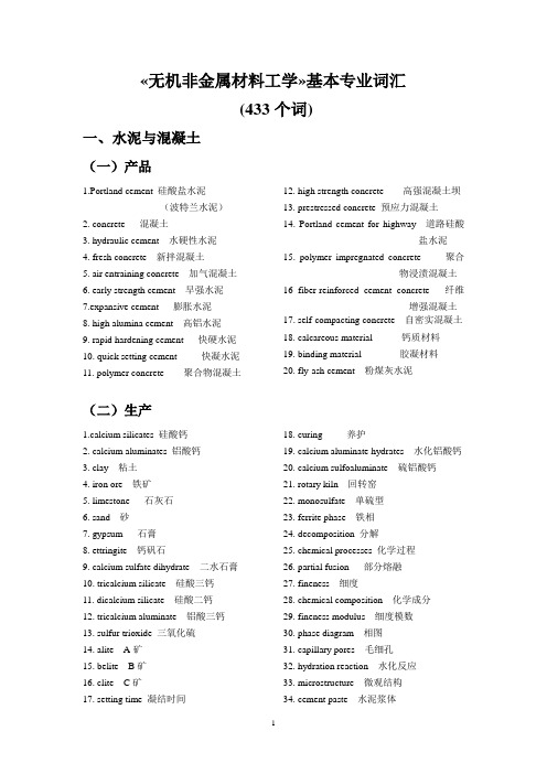
«无机非金属材料工学»基本专业词汇(433个词)一、水泥与混凝土(一)产品1.Portland cement 硅酸盐水泥(波特兰水泥)2. concrete 混凝土3. hydraulic cement 水硬性水泥4. fresh concrete 新拌混凝土5. air entraining concrete 加气混凝土6. early strength cement 早强水泥7.expansive cement 膨胀水泥8. high alumina cement 高铝水泥9. rapid hardening cement 快硬水泥10. quick setting cement 快凝水泥11. polymer concrete 聚合物混凝土12. high strength concrete 高强混凝土坝13. prestressed concrete 预应力混凝土14. Portland cement for highway 道路硅酸盐水泥15. polymer impregnated concrete 聚合物浸渍混凝土16 fiber-reinforced cement concrete 纤维增强混凝土17. self-compacting concrete 自密实混凝土18. calcareous material 钙质材料19. binding material 胶凝材料20. fly-ash cement 粉煤灰水泥(二)生产1.calcium silicates 硅酸钙2. calcium aluminates 铝酸钙3. clay 粘土4. iron ore 铁矿5. limestone 石灰石6. sand 砂7. gypsum 石膏8. ettringite 钙矾石9. calcium sulfate dihydrate 二水石膏10. tricalcium silicate 硅酸三钙11. dicalcium silicate 硅酸二钙12. tricalcium aluminate 铝酸三钙13. sulfur trioxide 三氧化硫14. alite A矿15. belite B矿16. clite C矿17. setting time 凝结时间18. curing 养护19. calcium aluminate hydrates 水化铝酸钙20. calcium sulfoaluminate 硫铝酸钙21. rotary kiln 回转窑22. monosulfate 单硫型23. ferrite phase 铁相24. decomposition 分解25. chemical processes 化学过程26. partial fusion 部分熔融27. fineness 细度28. chemical composition 化学成分29. fineness modulus 细度模数30. phase diagram 相图31. capillary pores 毛细孔32. hydration reaction 水化反应33. microstructure 微观结构34. cement paste 水泥浆体35. aggregate 集料36. crystallization 结晶37. alkali sulfates 硫酸碱38. carbonates 碳酸盐39. deterioration 劣化40. organic chemistry 有机化学41. inorganic chemistry 无机化学42. surface chemistry 表面化学43. thermodynamical 热力学的44. silica gel 硅酸凝胶45. pozzolanic 火山灰质的46. marine environment 海洋环境47. deicing salts 除冰盐48. concrete mixtures 混凝土配合比49. alkali-silica reactivity 碱硅反应50. harden 硬化51 active addition 活性混合材52. admixture 外加剂53. age 龄期54. broken stone 碎石55. calcium hydroxide 氢氧化钙56. calcium lignosulphonate 木质磺酸钙57. calcium silicate hydrate (CSH)水化硅酸钙58. alkali-aggregate reaction碱-集料反应59. clinker 熟料60. cement-water ratio 灰水比61. coarse aggregate 粗集料62. concrete mix 混凝土混合料63. crushing test 压碎试验64. gap grading 间断级配65. gradation 级配66. gravel 卵石67. normal distribution 正态分布68. hydrophilic aggregate 亲水集料69. hydrophobic aggregate 憎水集料70. initial set 初凝71 mortar 砂浆72. cement-based 水泥基73. pore 孔隙74. water reducer 减水剂75.waterproof mortar 防水砂浆76. phosphogypsum 磷石膏77. blast furnace slag 高炉渣78. fly ash 粉煤灰79. steel slag 钢渣80. corrosion inhibitors 阻锈剂81. mineral admixtures 矿物掺合料83. bound water 结合水84. boiler slag 沸腾炉渣85. admixture 外加剂86. hydration 水化87. milling 粉磨88. mortar 浆89.mineral constituent 矿物组成90. masonry 石质的二、玻璃(一)产品1. flat glass 平板玻璃2. vycor glass 高硅氧玻璃3. quartz glass 石英玻璃4. wired glass 夹丝玻璃5. float glass 浮法玻璃6. polished glass 机械磨光玻璃7. coloured glass 颜色玻璃8. heat-reflection glass 热反射玻璃9. conductive glass 导电玻璃10. ground glass 蒙砂玻璃11. ice glass 冰花玻璃12. sand blasted glass 喷砂玻璃13. strengthened glass 钢化玻璃14. laminated glass 夹层玻璃15. glazing glass 中空玻璃16. coating glass 镀膜玻璃17. bottle glass 瓶罐玻璃18. horticultural glass 圆艺用玻璃19. glass-ceramics 微晶玻璃20. lustre glass 虹彩玻璃21. luxury glass 陈设玻璃22. pressed glass 压制玻璃23. prescription glass24. parent glass 原玻璃25. laboratory glass化学仪器玻璃26. velvet-finish glass 丝光玻璃27. glass article 玻璃制品28. glass beaker 玻璃烧杯29. glass fabric 玻璃纤维30. glass foam 玻璃泡沫31. glass wall 玻璃幕墙32. double glazed unit 夹层玻璃33. electropane glass 玻璃导电膜34. fire-retardant glass 防火玻璃35. glass diamond 玻璃刀36. object glass 物镜37. obscured glass 毛玻璃38. optical glass 光学玻璃39. optical film 光学薄膜40. tempered glass 钢化玻璃41. boron glass 硼玻璃42. heat absorbing glass 吸热玻璃(二)生产1.colouring agent 着色剂2.fourcault process 有槽法3.pittsburgh process 无槽法4. Colburn Process 平拉法5.Asahi process 旭法6. ionic glasses 离子玻璃7. aluminium-boron anomaly 铝-硼效应8. aluminium effect 铝效应9. mixed alkali effect 玻璃的双碱效应10. invert glass 逆向玻璃11. chemical strengthened 玻璃的化学钢化12. air tempered 玻璃热钢化13. surface colouration 玻璃表面着色14. chemical polishing 化学抛光15. acid etching of glass 玻璃的化学蚀刻16. heat work 热加工17. surface treatment of glass玻璃的表面处理18. cold work 冷加工19. grinding and polishing 研磨抛光20. ionic colouration 离子着色21. semiconductor colouration 化合物着色22. short glass 短性玻璃23. metal-colloidah colouration金属胶体着色24. long glass 长性玻璃25. mixed alkali effect 玻璃的双碱效应26. hot mold blowing 热模吹制27. hot iron mold blowing 人工热模吹制28. machine stop 停止、引上29. machine-cylinder process 机械吹圆筒法30. surface of the melt 玻璃液面31.forming 成形32.spinodal dcomposion 亚稳分解33.nucleation and growth 成核生长34.nucleation process 核化过程35.phase transformation 相变36.cupola 冲天炉37. fining 澄清剂38. fining agent 澄清剂39. fining area(end)(zone) 澄清部,澄清带40. fining cell 澄清室池41. electric melting furnace 电熔窑42.tank furnace 玻璃熔窑分池窑43.pot furnace 坩埚窑44.drawing process 拉制成型45.blow process 吹制成型46.glass basis 玻璃基体47.‘L’glass ‘L’玻璃铅玻璃防辐照玻璃48. glass batch 玻璃配合料49. glass block 玻璃块50. glass coating 玻璃涂层51. glass component 玻璃组分52. glass current 玻璃液流53. glass decoration 玻璃装饰54. glass defect 玻璃缺陷55. glass drop 玻璃滴56. glass finishing 玻璃加工57. glass formation range 玻璃形成范围58. glass former 玻璃形成体59. glass frit 玻璃熔块60. glass melt 玻璃熔体61. glass melting furnace 玻璃熔窑62. glass phase 玻璃相63. fine seed 灰泡64. float bath 锡槽65. nucleus 晶核66. nucleating agent 晶核剂67. glass yield 玻璃获得率68. glassy state 玻璃态69. heat storage 蓄热70. crystallization 析晶71. crystal nucleus 晶核72. metal level 玻璃液面73. metaphase 介稳相74. occlusion 玻璃夹杂物75. patch of crizzles 表面微裂纹76. fusing 熔化77. fusing point 熔化温度78. refine 澄清79. deformation point 变形温度点80. red edge 红边(抛光玻璃缺陷)81. speck 斑点82. deformation 变形83. ash contamination 落脏84. crack 裂纹85. bubble or blister 起泡86. pinhole 棕眼87. exposed body 缺釉88. tint unevenness 色泽不良89. sandwich 夹层90. excess glaze 釉缕91. waviness 波纹92. smoke staining 烟熏93. orange peel 橘釉94. knot 节瘤95. bubble 气泡96. toed-in finish 凹口97. crater type drip 锡滴坑98. string 细条纹,线道99. stone 结石三、陶瓷(一)产品1. china ware 瓷器2.earthenware 陶器3. ordinary ceramics 普通陶瓷4. special ceramics 特种陶瓷5. bioceramics 生物陶瓷6. semiconductive ceramics 半导体陶瓷7.conductive ceramics 导电陶瓷8.superconductive ceramics 超导陶瓷9.magnetic ceramics 磁性瓷10.piezoelectric ceramics 压电陶瓷11.capacitor ceramics 电容器陶瓷12.structural ceramics 结构陶瓷13.advanced ceramics 先进陶瓷14.fine ceramics 精细陶瓷15.engineering ceramics 工程陶瓷16. new ceramics 新型陶瓷17.modern ceramics 近代陶瓷18. high technology ceramics 高技术陶瓷19.high performance ceramics 高性能陶瓷20. construction ceramics 建筑陶瓷21. electronic ceramics 电子陶瓷22. engineering ceramics 工程陶瓷23. foamed ceramics 泡末陶瓷24. functional ceramics 功能陶瓷25. honeycomb ceramics 蜂窝陶瓷26. bone china 骨灰瓷27. feldspar china 长石瓷28. vitrified china 玻化瓷29. fine earthenware 精陶30.talc earthenware 滑石陶器31.electrical porcelain 电瓷2.household porcelain 日用瓷33.sanitary porcelain 卫生瓷34.stoneware 炻器35. altar red 祭红36. bright glaze 光泽釉37. clear glaze 透明釉38. flambè (glaze ) 铜红釉39. fritted glaze 熔块釉40. fusible glaze 易熔釉41. glossy glaze 光泽釉42. ground glaze 底釉43. hard glaze 高温釉44. matt glaze 无光釉45. opaque glaze 乳浊釉,不透明釉46. photochromic glaze 变色釉47. satin glaze 缎光釉,丝光釉48. salt glaze 盐釉49. soft glaze 中、低温釉50.Tang triclour 唐三彩51. transmutation glaze 窑变釉52. vapour glaze 挥发釉53. table ware 餐具54. tile 墙地砖55. sanitary ware 卫生洁具56.sample/facing brick 清水砖(二)生产1. lubricants 润滑剂2. briders 结合剂3.deflocculants 解凝剂、解胶剂、稀释剂4. fluxing agent 助熔剂5. glost fire 釉烧6. glazing 施釉7. filter-pressing 压滤8. temper 练泥9. blend 混料10. pug machine 练泥机11. consolidated and extruded挤压12. stir 搅拌13. sieve 筛分,筛子14. slip casting 注浆成型15. spray drying 喷雾干燥16. atomize 雾化17. moisture content 含水量18. plastic making 可塑成型19. dry pressing 干压成型20. plaster mould 石膏模21. drying shrinkage 干燥收缩22. biscuit firing 素烧23. extrusion 挤压成型24. jolleying 阴模旋坯成型25. jiggering 阳模旋坯成型26. unfired article 生坯27. isostatic pressing 等静压成型28. hot pressing 热压成型29. decoration 装饰30. age 陈腐31. removal from the mould 脱模32. grinding 研磨33. dipping 浸釉34. kiln 窑炉35. curtain coating 淋釉36. spraying 喷釉37. electrostatic spray 静电施釉38. fluidised bed 流化床施釉39. pressing 干法施釉40. sintering 烧结41. refiring 重烧42. tw ice firing 二次烧成43. resistance furnace 电阻炉44. flame furnace 火焰窑炉45. electric furnace 电热窑炉46. shuttle kiln 梭式窑47. down draught kiln 倒焰窑48. intermittent kiln 间歇窑49. roller-hearth kiln 辊道窑50. tunnel kiln 隧道窑51. liquid phase sintering 液相烧结52. induction furnace 感应炉53. electronic impact furnace 电子束炉54. plasma furnace 等离子炉55. reacti on sintering 反应烧结56. heat densification 热致密化57. self-propagating high-temperature synthesis 高温自蔓延烧结58. glaze formula 釉式四、耐火材料1.principal crystalline phase 主晶相2. matrix 基质3. secondary crystalline phase 次晶相4. mineralizer矿化剂5. bulk refractory不定形耐火材料6. magnesia brick rich in CaO 镁钙砖7. high-silica magnesite brick 镁硅砖8. magnesite-chrome brick 镁铬砖9. magnesite-alumina brick 镁铝砖10. magnesite brick 普通镁砖11. magnesite refractory 镁质耐火材料12. fused-quartz product 熔融石英制品13. quartzitic sandston 白泡石14. siliceous refractory 硅质耐火材料15. high-alumina refractory 高铝质耐火材料16. fireclay refractory 粘土质耐火材料17. aluminasilicate refractory 硅酸铝质耐火材料18.graphite refractory 石墨耐火材料19.carbon refractory 炭素耐火材料20.refractory mortar 耐火泥21.slinger mix 投射料22.gunning mix 喷射料23.refractory ramming material 捣打料24.plastic refractory 可塑耐火材料25. refractory castables 浇注料26.binder 胶结剂27.refractory powde r掺合料28.aggregate 骨料29.refractory fibre 耐火纤维31.light weight refractory 轻质耐火材料30.fused cast refractory 熔铸耐火材料五、性能1. elasticity 弹性2. brittleness 脆性3. hardness 硬度4. surface tension 表面张力5. viscosity 粘度6. thermal shock resistance 耐热震性7. glossiness 釉的光泽度8. elastic modulus 弹性模数9. strength 强度10. whitness 白度11.refractoriness under load 荷重软化温度12. vacuum resistance 耐真空性13.volume stability under high temperature高温体积稳定性14. durability 耐久性15. moisture 湿度16.soundness 安定性17.workability 工作性18.adhesiveness 粘附性19.cohesiveness 粘聚性20.bleeding 泌水性21. creep 徐变,蠕变22.crushing value 压碎指标23.density 密度pressive strength 抗压强度25.frost resistance 抗冻性26.flexural strength 弯曲强度27. normal consistency 标准稠度28.modulus of elasticity 弹性模量29.porosity 孔隙率31 Corrosion resistance 耐腐蚀性32. weaterbility 耐候性32. Freeze-thaw cycles 冻融循环33. Toughness 韧性34. compressive strength 抗压强度35. bending strength 抗弯强度36. glass density 玻璃密度37. refractive index 折射率38.thermal stress 热应力。
材料科学与工程专业英语
2.6 semiconductorFollowing the discussion of intrinsic ,elemental semiconductors we note that the fermi function indicates that the number of charge carriers increases exponentially with temperature. This effect so dominates the conductivity of semiconductors that conductivity also follows an exponential increase with temperature(an example of an arrhenius equation ).This increase is in sharp contrast to the behavior of metals.We consider the effect of impurities in extrinsic,elemental semiconductors.Doping a group IV a material(such as Si) with a group V a impurity (such as P)produces an n-type semiconductor in which negative charge carriers(conduction electrons)dominate.The “extea”electron from the group V A addition produces a donor level in the energy band structure of the semiconductor.As with instrinsic semiconductors,extrinsic semiconduction exhibits arrhenius behavior.in n-type material, the temperature span between the regions of extrinsic and insrinsic behavior is called the exhaustion range .A p-type semiconductor is produced by doping a group IV a material with a group III a impurity(such as Al).The group III A element has a “missing”electronproducing an acceptor level in the band stucture and leading to formation of positive charge carriers (electron holes). The region between extrinsic and instrinsic behavior for p-type semiconductors is called the saturation range . Hall effect measurements can distinguish between n-type and p-type conduction.Compound semiconductors usually have an MX composition with an average of four valence electrons per atom .The III-V and II-VI compounds are the common examples .amorphous semiconductors are the non-crystalline materials with semiconducting behavior.Elemental and compound material are both found in this category .To appreciate the applications of semiconductors,we review a few decades.the solid state rectifier (or diode) contains a single p-n junction .Current flows readily when this junction is forward biased but is almost completely choked off when reverse biased.the transistor is a device consisting of a pair of nearby pn junctions.The net result is a solid state amplifier. Replacing vacuum tubes with solid state elements such as these produced substantial miniaturization of electrical circuits.Further miniaturization has resulted by the production of microcircuis consisting of precise parrerns of n-type andp-type regions on a single crystal chip.The major electrical properties needed to specify an intrinsic semiconductor are band gap,electron mobility,hole mobility,and conduction electron density (=electron hole density ) at room temperature.For extrinsic semiconductors,one needs to specify either the donor level (for n-type material) or the acceptor level (for p-type material).2.7 compositesOne category of structural engineering material is that of composites .These materials involve some combination of two or more components from the “fundamental”materal types .A key philosophy in selecting composite materials is that they provide the “best of both worlds”that is ,attrative properties from each component. A classic example is fiberglass.The strength of small diameter glass fibers is combined with the ductility of the polymetric matrix.The combination of these two components provides a product superior to either component alone .Many composites,such as fiberglass,involve combinations that cross over the boundaries of different kinds of materials. Others,such as concrete,involve different component from within a single material type.In general,we shall use a fairly narrow definition ofcomposites.We shall consider only thode material thata combine different components on the microscopic(rather than macroscopic )scale .We shall noot include multiphase alloys and ceramics ,which are the result of routine processing.Similarly,the microcircuits be discussed later are not include because each component retains its distinctive character in these material systems. In spite of these restrictions,we shall find this category to include a tremendously diverse collection of materials,from the common to some of most sophisticated.We shall consider three categories of composites mateials. Conveninently ,these categories are demonstrated by three of our most common structural material ,fiberglass ,wood,and concrete .Fiberglass(or glass fiber reinforced polymer ) is an excellent example of a human made fiber reinforced composite.The glass-polymer system is just one of many important example .The fiber reinforcement is generally found in one of three primary configutations: aligned in a single direction ,randomly chopped,or woven in a fabric that is laminated with the matrix.Wood is a stuctural analog of fiberglass ,that is ,a natural fiber reinforced composite.The fibers of wood are elongated,biological cells. The matrixcorresponds to lignin and hemicellulose deposits.concrete is our best example of an aggregate composite, in which particles rather than fibers reinforce amatrix common concrete is rock and sand in a calcium aluminosilicate (cement)matrix.While concrete has been a construction material for centuries ,these are numerous c composites developed in recent decades that use a similar particulate reinforcement concept.The concept of property averaging is central to understanding the utility of composite material.an important example is the elastic modulus of a composite .The modulus is a sensitive function of the gemetry of the reinforcing component.similarly important is the srength of the interface betweeen the reinforcing component and the matrix .We sahll concentrate on these mechanical properties of composites in regard for their wide use as structural materials.So caaled “advanced”composites have provided some unusually attractive features,such as high strrenth to weight ratios.Some care is required in citing these properties,as they can be highly directional in nature.2.6there are numerous uses of piezoelectrics. for instance, plates cut from a single crystal can exhibit a specific naturalresonance frequency(i.e., the frequency of an electromagnetic wave that causes it to vibrate mechanically at the same frequency); these can be used as a frequency standard in highly stable crystal controlled clocks and in fixed frequency communications devices. other resonant applications include selective wave filters and transducers(e.g., for ultrasonic cleaning and drilling) and non-resonant devices(e.g., accelerometers, pressure gauges, microphone pickups) are dominated by ceramic piezoelectrics.2.7.3 fiberglass was a convenient and familiar example of fiber reinforced composites. Similarly ,concrete is an excellent example of an aggregate composite. As with wood,this common construction material is used in staggering quantities. The weight of concrete used annually exceeds that of all metals combined.For concrete, the term “aggregate”refers to a combination of sand(fine aggregate) and gravel(coarse aggregate). This component of concrete is a “natual”material in the same sense as wood. Ordinarily ,these materials are chosen for their relatively high density and strength. A table of aggregate compositions would be complex and largely meaningless. In general, aggregate materials are geological silicates chosenfrom locally available deposits. As such, these materials are complex and relatively impure examples of the crystalline silicates. Igneous rocks are common examples. “igneous”means solidified from a molten state. For quickly cooled igneous rocks ,some fraction of the resulting material may be non-crystalline, corresponding to the glassy silicates. The relative particle sizes of sand and gravel are measured(and controlled) by passing these materials through standard screens(or sieves). The reason for a combination of fine and coarse aggregate in a given concrete mix is that the space is more efficiently filled by a range of particle sizes. The combination of fine and coarse aggregate accounts for 60 to 75 percent of the total volume of the final concrete. Modern concrete uses portland cement,which is a calcium aluminosilicate. There are five common types of portland cement. They vary in the relative concentrations of four calcium containing minerals. The matrix is formed by the addition of water to the appropriate cement powder. The particle sizes for the cement powers are relatively small compared to the finest of the aggregates. Variation in cement particle size can strongly affect the rate at which the cement hydrates. As one might expect from inspecting the complexcompositions of portland cement, the chemistry of the hydration process is equally complex.In ploymer technology, we noted several “additives”which provided certain desirable features to the end product. In cement technology , there are a numble of admixtures,which are additions providing certain features. Any component of concrete other than aggregate,cement,or water is, by definition ,an admixture. One of the admixtures is an “air entrainer”which reminds us that air can be thought of as a fourth component of concrete. The air entrainer admixture increases the concentration of entrapped air bubbles, usually for the purpose of workability(during forming) and increased resistance to freeze thaw cycles.Why concrete is an important engineering material, a large numble of other composite systems are based on particle reinforcement. Particulate composites refer specifically to systems with relatively large size dispersed particles(at least several micrometers in diameter),and the particles are in relatively high concentration(greater than 25 and frequently between 60 and 90) of small diameter oxide particles. The oxide particles strengthen the metal by serving as obstacles to dislocation motion.2.7.2 like so many accomplishments of human beings, those fiber reinforced composites imitate nature. Common wood is such a composite, which serves as an excellent structural material. In fact, the weight of wood used each year in the Uited Sates exceeds the combined total for steel and concrete. We find two categories , softwoods and hardwoods. These are relative terms, although softwoods generally have lower strengths. The fundamental difference between the categories is their seasonal nature. Softwoods are “evergreens”with needlelike leaves and exposed seeds. Hardwoods are deciduous( i.e., lose their leaves annually)with covered seeds( i.e.,nuts)The microstructure of wood illustrates its commonality with the human-made composites. The dominant feature of the microstructure is the large number of tubelike cells oriented vertically. These longgitudinal cells are aligned with the vertical axis of the tree. There are some radial cells perpendicular to the longitudinal ones. As the name implies, the radial cells extend from the center of the tree trunk out radically toward the surface. The longitudinal cells carry sap and other fluids critical to the growth process. Early seaon cells are of larger diameter than later season cells. This growthpattern leads to the characteristic “ring structure”which indicates the tree’s age. The radial cells store food for the growing tree. The cell walls are composed of cellulose. The strength of the cells in the longitudinal direction is a function of fiber alignment in that direction. The cells are held together by a matrix of lignin and hemicellulose. Lignin is a phenol propane network ploymer, and hemicellulose is ploymeric cellulose with a relatively low degree of ploymerization. Related to this ,the dimensions as well as the proper ties of wood vary significantly with atmospheric moisture levels. Care will be required in specifying the atmospheric conditions for which mechanical property data apply.2.7.1 let us begin by concentrating on fiberglass, or glass fiber reinforced ploymer. This is a classic example of a modern composite system. A typical fracture surface of a composite shows fibers embedded in the ploymeric matrix, such fibers may have different composition since each is the result of substantial development that has led to optimal suitability for specific applications. For example, the most generally used glass fiber composition is E glass, in which E stands for its especially low electrical conductivity and its attractiveness as a dielectric. Its popularity in structural composites is related tothe chemical durability of the borosilicate composition. We should note that optimal strengh is achieved by the aligned, continuous fiber reinforcement. In other words, the strength is highly anisotropic.The fiber reinforced composites include some of the most sophisticated materials developed by man for some of the most demanding engineering applications. Important examples include boron reinforced aluminum, graphite epoxy, and al reinforced aluminum. Metal fibers are frequently small diameter wires. Especially high strength reinforcement come from “whiskers”which are small, single crystal fibers that can be grown with a nearly perfect crystalline structure. Unfortunately , whiskers cannot be grown as continuous filaments in the manner of glass fibers or metal wires.2.5polymerpolymers are chemical compounds that consist of long,chainlike molecules made up of multiple repeatinf units.The term polyner was coined in 1832 by the Swedish chemist Jins Jacob Berzelius from the Greek pols,or "many" and meros,or "parts."Polymers are also referred to as macromolecules,or "gaint molecules"-a term introduced by the German chemist Hermann Staudinger in 1992.Some gaintmolecules occur maturally.Proteins ,for example ,are natural polymers of amino acids that make up much of the structural material of animals;and the polymers deoxyribonucleic acid(DNA) and ribonucleic acid(RNA) are liner strands of nucleotides that define the genetic make up of living organisms.Other examples of natural polmers are silk ,wool.natural rubber,cellulose ,and shellac.There materials have been known and exploited since ancient times.Indeed,people in what is now Switzerland cultivates flax,a source of polymeric cellulose fibres,during the Neolithic Period,or New Stone Age,some 10 000 years ,while other ancients collected proteinaceous wool fibers from sheep and silk fibers from silkworms.About five millennia ago,tanners produced leather through the cross linking of proteins by gallic acid forming the basis of the oldest industry in continuous production.Even embalming,the art for which ancient Egypt is famous is based on the condensation and cross linking of proteins with form aldehyde.Early developments in polymer technology,taking place in the 19th century,involved the conversion of natural polymers to more useful products-for example,the conversion of cellulose,obtained from cotton or wood,into celluloid,one ofthe first plastic.Before the 1930s only a small number of synthetically produced polymers were available commercially,but after that period and especially after World War II,synthetic compounds came to dominance.Derived principally from the refining of petroleum and natural gas,synthetic polymers are made into the plastics,rubbers,man-made fibres,adhesives,and surface coatings that have become so ubiquitous in modern life.As an important materials,the polymers are available in a wide variety of commercial forms:fibers,thin films and sheets,foams and in bulk.A common synonym for polymers is "plastic",a name derived from the deformability associated with the fabrication of most polymeric products.To some critics,"plastic" is a synonym for modern culture.Accurate or not,it represents the impact that this complex family of engineering materials has had on our society.Polymers are distinguished from our previous types of materials by chemistry.Metal,ceramics.and glasses are inorganic materials.The polymers discussed here are organic.The student should not be concerned about a lack of background in organic chenistry.This passage is intended to provide any of the fundamentals of organic chemistry neededto appreciate the unique nature of polymeric materials.We begin our discussion of polymers by investigating polymerization,the process by which long chain or network molecules are made from relatively small organic molecules.The structural features of the resulting polymers are rather unique compared to the inorganic materials.Ingeneral,the ,elting point and rigidity of polymers increase with the extent of plymerization and with the complexity of the molecular structure.We shall find that polymers fall into one of two main categories.Thermoplastic polymers are materials that become less rigid upon heating,and thermosetting polymers become more rigid upon heating.For both categories,it is important to appreciate the roles played by additives,which provide important features such as color and resistance to combustion.As with ceramics and glasses,we shall discuss important mechanical and optical properties of polymers.Mechanically,polymers exhibit behavior associated with their long chain molecular structure.Examples include viscoelastic and elastomeric deformation .Optical properties such as transparency and color,so important in ceramic technology,are also significant in the selection of polymers.2.5.1 PolymerizationThe term polymer simply means "many mers" where mer is the building block of the long chain or network molecule.There are two distinct ways in which a poly merization reaction can take place.Chain growth(also known as addition polymerization)involves a rapid "chain reaction" of chemically activated monomers.Step growth(also known as condensation polymerization)involves individual chemical reactions between pairs of reactive monomers and is a much slower process.In either case,the critical feature of a monomer,which permits it to join with similar molecules and form a polymer,is the presence of reactive sites,that is double bonds(chain growth) or reactive functional groups (step geowth).Each covalent bond is a pair of electrins shared between adjacent atoms.The double bond is two such pairs.The chain growth reaction converts the double bond in the monomer to a single bond in the mer.The remaining two electrons become parts of the single bonds joining adjacent mers.2.5.2 Thermal Plastic PolymersThermoplastic polymers become soft and deformable upon heating.This is characteristic of linear polymeric molecules.The high temperature plasticity is due to the ability of the molecules to slide past one another.This is another example of a thermally activated,or Arrhenius process.In this sence ,thermoplastic materials are similar to metals that gain ductility at high temperatures.The key distinction between thermoplastics and metals is what we mean by "high" temperatures.The secondary bonding,which must be overcome to deform thermoplastics,may allow substantial deformation around 100,whereas metallic bonding generally restricts creep deformation to temperature closer to 1000 in typical alloys.It should be noted that,as with metals,the ductility of thermoplastic polymers is lost upon cooling.2.5.3 Thermal Setting PolymersThermosetting polymers are the opposite of the thermoplastics.They become hard and rigid upon heating.Unlike thermoplastic polymers,this phenomenon is not lost upon cooling.This is characteristic of network molecular structures formed by the step growth mechanism.The chemical reaction "steps" are enhanced byhigher temperatures and are irreversible,that is,the polymerization remains upon cooling.In fabricating thermosetting products,they can be removed from the mold at the fabrication temperature (typically 200 to 300).By contrast,thermoplastics must be cooled in the mokd to prevent distortion.It might also be noted that network copolymers can be formed similar to be the block and graft copolymers.The network copolymer will result from polymerization of a combination of more than one species of polyfunctional monomers.2.5.4 AdditivesCopolymers and blends were discussed above as analogs of metallic alloys.There are aeveral other alloylike additives that traditionally have been used in polymer technology to provide specific characteristics to the polymers .A plasticizer is added to soften a polymer.This addition is essentially blending with a low molecular weight (approximately 300 amu) polymer.A filler ,on the other hand .is added to strengthen a polymer primarily by restricting chain mobility.it also provides dimensional stability and reduced cost.Relatively inertmaterials are used.Examples include shortchanger cellulose (and organic filler) and asbestos (and inorganic filler).Roughly one third of the typical automobile tire is a filler (i.e.,carbon black).Reinforcements such as glass fibers are also categorized as additives but produce such fundamentally different materials (e.g.,fiberglass) that they are properly discussed later on composites.Stabilizers are additives used to reduce polymer degradtion.They represent a complex set of materials because of the large variety of degradation mechanisms(oxidation,thermal,and ultraviolet).As an example,polyisoprene can absorb up to 15% oxygen at room temperature with its elastic properties being destoryed by the first 1%.Natural rubber latex contains complex phenol groups that retard the room temperature oxidation reactions.However,these naturally occurring antioxidants are not effective at elevated temperatures.Therefore ,additional stabilizers(e.g.,other phenols,amines,sulphur compounds,etc.)are added to rubber intended for tire applications.Flame retardant are added to reduce the inherentcombustibility of certain polymers such as bustion is simply the reaction of a hydrocarbon with oxygen accompanied by substantial heat evolution.Many polymeric hydrocarbons exhibit combustibility.Others,such as polyvinylchloride(PVC),do not.The resistance of PVC to combustion appears to come from the evolution of the chlorine atoms from the polymeric chaim.These halogens hinder the process of combustion by terminating free radical chain reactions.Additives that provide this function for halogen free polymers include chlorine,bromine,and phosphorus containing reactants.Colorant are additions to provide color to a polymer where appearance is a factor in materials selection.Two types of colorants are used,pigments and dyes.A pigment is an insoluble,colored material added in powered form.Typical examples are crystalline ceramics such as titanium oxide and aluminum silicate,although organic pigments are availble.Dyes are soluble,organic colorants that can provide transparent colors.2.5.5 Viscoelastic DeformationAt relatively low temperature,polymers are rigid solids anddeform elastically.At relatively high temperatures,they are liquidlike and deform viscously.The boundary between elastic and viscous behavior is again known as the glass transition temperature,Tg.However,the variation in polymer deformation with temperature is not demonstrated in the same way.For glassws,the variation in viscosity was plotted against temperature.For polymers,the modulus of elasticity is plotted instead of viscosity.There is a drastic and complicated drop in modulis with temperature for a typical,commercial thermoplastic with approxinately 50% crystallinity.THe magnitude of the drop is illustrated by the use of a logarithmic scale for modulus.At "low" temperatures (well below Tg),a rigid modulus occurs corresponding to mechanical behavior reminiscent of metals and ceramics.However,the substantial component of secondary bonding in the polymers cause the modulus for these materials to be substantially lower than the ones found for metals and ceramics,which were fully bonded by primary chemical bonds (metallic,ionic,and covalent).In the glass transition temperature (Tg) range,the modulus drops precipitously and the mechanical behavior is leathery.The polymer can be extensively deformed and slowly returns to itTys original shape upon stress removal.Just above Tg,arubbery plateau is observed.In this region,extensive deformation is possible with rapid spring back to the original shape when stress is removed.These last two regions(leathery and rubbery) extend our understanding of elastic deformation.Sometimes the elastic deformation meant a relatively small strain directly proporyional to applied stress.For polymers,extensive,non-linear deformationcan be fully recovered and is ,by definition,elastic.This concept will be explored shortly when we discuss elastomers,those polymers with predominant rubbery region.2.5.6 ElastomersTypical linear polymers exhibits a rubbery deformation region.For certain polymers known as elastomers,the rubbery plateau is pronounced and establishes the normal room temperature behavior of these materials.(For these materials,the glass transition temperature is below room temperture.)This subgroup of thermoplastic polymers includes the natural and synthetic rubbers (such as polyisoprene).These materials provide a dramatic example of the uncoiling of a linear polymer.As a practical matter,the complete uncoiling of the molecule is not achieved,but huge elastic strains dooccur.The stress-strain curve for the elastic deformation of an elastomer shows dramatic contrast to the stress-strain curve for a common metal.In that case,the elastic modulus was constant throughout the elastic region (stress was directly proportional to strain).While the clastic modulus (slope of the stress-strain curve) increases with increasing strain.For low strains,the modulus is low corresponding to the small forces needed to overcome secondary bonding and to uncoil the molecules.For high strains,the modulus rises sharply,indicating the greater force needed to stretch the primary bonds along themolecular "backbone".In both region,however,there is a significant componrnt of secondary bonding involved in the deformation mechanism,and the moduli are much lower than those for common metals and ceramics.Tabulated values of moduli for elastomers are generally for the low strain region in which the materials are primarily used.Finally,it is important to emphasize that we are talking about elastic or temporary deformation.The uncoiled polymer molecules of an elastomer recoil to their original length upon removal of stress.2.5.7 Stress RelaxationFor metals and ceramics,we found creep deformation to be an important phenomenon at high temperatures (greater than one half the absolute melting point).A similar phenomenon,termed stress relaxation,occurs in polymers.This is perhaps more significant to polymers.Because of their loe melting points,stress relaxation can occur at room temperature.A familar example is the rubber band,understress for a long period of time,which does not snap back to its original size upon stress removal.2.4(88)Chemical substitutions in the BaTio3 structure can alter a number of ferro electric properties.For example,BaTio3 exhibits a large peak in dielectric constant near the Curie point-a property that is undesirable for stable capactior applications.This problem may be addressed by the substitution of lead (**) for (**),which increases the Curie point;by the substitutionof strontium,which lowers the Curie point;or by substituting Ba with calcium,which broadens the temperature range at which the peak occurs.Barium titanate can be produced by mixing and firing barium carbonate and titanium dioxide,but liquid-mixtechniques are increasingly used in order to achieve better mixing,precise control of the barium titanium ratio,high purity,and submicrometre particle size.Processing of the resulting powder varies according to whether the capacitor is to be of the disk or multilayer type.Disks are dry pressed or punched from tape and then fired at temperatures between 1250 and 1350.Silver-paste screen printed electrodes are bonded to the surfaces at 750.Leads are soldered to the electrodes,and the disks are epoxy coated or wax impregnated for encapsulation.The capacitance of cermic disk capacitors can be increased by using thinner capacitors;unfortunately,fragility result.Multilayer capacitors overcome this problem by interleaving dielectric and electrode layers.The electrode layers are usually palladium or a palladium-silver alloy.These metals have a melting point that is higher than the sintering temperature of the ceramic,allowing the two materials to be cofired.By connecting alternate layers in paralled,large capacitance can be realized with the MLC.The dielectric layers are processed by tape casting or doctor blading and then yer thickness as small as 5 micrometres have been achieved.Finished "build" of dielectric and electrode layers are。
- 1、下载文档前请自行甄别文档内容的完整性,平台不提供额外的编辑、内容补充、找答案等附加服务。
- 2、"仅部分预览"的文档,不可在线预览部分如存在完整性等问题,可反馈申请退款(可完整预览的文档不适用该条件!)。
- 3、如文档侵犯您的权益,请联系客服反馈,我们会尽快为您处理(人工客服工作时间:9:00-18:30)。
Structural order in glassy waterNicolas Giovambattista,1Pablo G.Debenedetti,1Francesco Sciortino,2and H.Eugene Stanley3 1Department of Chemical Engineering,Princeton University,Princeton,New Jersey08544-5263,USA 2Dipartimento di Fisica and INFM Udr and SOFT:Complex Dynamics in Structured Systems, Universita’di Roma“La Sapienza”–Piazzale Aldo Moro2,I-00185,Roma,Italy3Center for Polymer Studies and Department of Physics,Boston University,Boston,Massachusetts02215,USA͑Received24February2005;published30June2005͒We investigate structural order in glassy water by performing classical molecular dynamics simulations using the extended simple point charge͑SPC/E͒model of water.We perform isochoric cooling simulations across the glass transition temperature at different cooling rates and densities.We quantify structural order by orientational and translational order metrics.Upon cooling the liquid into the glassy state,both the orienta-tional order parameter Q and translational order parameterincrease.At T=0K,the glasses fall on a line in the Q-plane or order map.The position of this line depends only on density and coincides with the location in the order map of the inherent structures͑IS͒sampled upon cooling.We evaluate the energy of the IS,e IS͑T͒, andfind that both order parameters for the IS are proportional to e IS.We also study the structural order during the transformation of low-density amorphous ice͑LDA͒to high-density amorphous ice͑HDA͒upon isother-mal compression and are able to identify distinct regions in the order map corresponding to these glasses. Comparison of the order parameters for LDA and HDA with those obtained upon isochoric cooling indicates major structural differences between glasses obtained by cooling and glasses obtained by compression.These structural differences are only weakly reflected in the pair correlation function.We also characterize the evolution of structural order upon isobaric annealing,leading at high pressure to very-high density amorphous ice͑VHDA͒.DOI:10.1103/PhysRevE.71.061505PACS number͑s͒:64.70.Pf,61.43.Fs,02.70.NsI.INTRODUCTIONCrystalline solids are characterized by a periodic structureand,therefore,by the presence of long range order.A well-defined theoretical and experimental framework is availablefor characterizing the structure of crystals͓1͔.On the otherhand,numerous materials found in nature and widely utilizedin technology exist in an amorphous state͑e.g.,glasses andliquids͓͒2͔.Characterizing the structure of amorphous ma-terials is a challenging task because such systems organizeover short distances and show no long-range order.More-over,the local structure in such materials is not unique and itcan change throughout the sample.Therefore,new tools arerequired to characterize the structure of amorphous materials.One promising approach is to develop order metrics͑orderparameters͒that quantify certain statistical properties of thestructure͓3͔.Recent work in this direction has been per-formed on the hard-sphere͓4,5͔and Lennard-Jones͑LJ͓͒6͔particle systems.Structural order was characterized with twometrics,a translational order parameterquantifying the ten-dency of particle pairs to adopt preferential separations,anda bond-orientational order parameter Q quantifying correla-tions between the bond angles defined by a given particleand its nearest neighbors.This approach distinguishes itselfnot by the use of order metrics themselves,which have beenused before͑e.g.,Ref.͓7͔͒,but by the idea of an order map,in which different states are mapped onto a plane whose axesrepresent the order metrics͓4,5͔.The order map for theLennard-Jones and hard-sphere systems consists of a line,indicating that the two order metrics are not independent ͓5,6͔.Extension of these ideas to liquid water has proven to be most useful.In Ref.͓8͔,the structural order of cold liquid water was investigated and found to be closely related to the well-known dynamic͓9–11͔and thermodynamic͓12͔anomalies of this substance.It was found that there exists a region in the phase diagram bounded by loci of maximum orientational order and minimum translational order within which the dynamic and thermodynamic anomalies occur. Water’s order map was found to be more complex than for simpler,spherically symmetric systems.State points define a two-dimensional region in the order map,implying that ori-entational and translational order are in general independent. Remarkably,however,it is found that the region where water exhibits dynamic or thermodynamic anomalies defines a line in the order map,which implies that when water behaves anomalously,its translational and orientational order metrics are no longer independent,but are instead strictly correlated. This property was then used to quantify threshold values of the order metrics needed in order for various anomalies to occur͓8͔.Similar͑though not identical͒behavior was found to occur in another tetrahedral liquid,silica͓13͔.Notable among water’s peculiarities is the fact that it ex-hibits polyamorphism͓14–16͔,i.e.,the presence of more than one glassy form.Uniaxial compression of ice-I h͓17͔or ice-I c͓18,19͔at T=77K to pressures Pտ1GPa produces adisordered high-density material named high-density amor-phous ice͑HDA͒.If HDA is recovered at T=77K and P=1bar and then heated isobarically,it transforms irrevers-ibly at TϷ125K to a disordered low-density material named low-density amorphous ice͑LDA͓͒17,20͔.Moreover,LDA transforms to HDA when compressed at T=77K to P =0.6GPa͓20,21͔.The LDA-HDA transformation is revers-ible above TϷ130K͓22͔.Furthermore,because it is very sharp and shows hysteresis,it has been suggested that thePHYSICAL REVIEW E71,061505͑2005͒LDA-HDA transformation is afirst-order transition͓22–24͔. The LDA-HDA transition plays a central role in one of the thermodynamically consistent scenarios that have been pro-posed to explain the experimentally observed properties of supercooled water͓16͔.There are several other routes to producing amorphous ice ͓14–16͔in addition to those mentioned above.Because glasses are nonequilibrium materials,their properties are history-dependent,and the specific procedure followed in the glass preparation may lead to different amorphous forms.It is not clear whether all the different amorphous ices can be classified into two families͓25–27͔,one corresponding to LDA and the other to HDA.One complication standing in the way of such a satisfyingly simple view is the experimen-tal observation that HDA,when annealed or heated at high pressure becomes appreciably denser.The resulting glass is called very-high density amorphous ice͑VHDA͒or relaxed HDA͑RHDA͓͒28͔.Whether VHDA/RHDA is simply yet another form of glassy water or whether,as suggested by simulations͓29,30͔,it is the more stable form to which HDA relaxes irreversibly is a question currently under investiga-tion.It should be evident from the preceding discussion that a precise characterization of structural order in water glasses is of considerable interest.The purpose of the present work is to provide such a characterization.In particular,͑i͒we use the order metric approach introduced in Ref.͓8͔for equilib-rium liquid water to quantify structural changes that occur when liquid water is cooled isochorically to the glassy state;͑ii͒we quantify the changes in structural order that accom-pany the LDA→HDA transformation;͑iii͒we investigate structural evolution during the annealing/isobaric heating of the amorphous ices obtained upon compression of LDA;and ͑iv͒we compare the location in the order map of the various glasses obtained in͑i͒,͑ii͒,and͑iii͒.By doing this,we are able to characterize quantitatively structural differences be-tween samples of amorphous ice obtained by different pro-cedures.In recent related work,Guillot and Guissani͓31͔performed computer simulations of glassy water obtained along different paths.They used the radial distribution func-tion and structure factor to study the structure of the different glasses.In this work,we instead use the order map approach. As we show below,this approach allows a precise and sen-sitive characterization of structure.This work is organized as follows.In the next section,we present the simulation details.In Sec.III,we study the local structure when the liquid is cooled isochorically across the glass transition at different cooling rates and for different densities.We study both the structure in the instantaneous configurations and in the corresponding potential energy minima attained by steepest descent mapping͑inherent struc-tures,IS͒.In Sec.IV,we study the evolution of structural order during the LDA→HDA transformation,and upon an-nealing͑i.e.,isobaric heating͒different glasses obtained dur-ing the compression procedure.The comparison of the local structure of the glasses obtained with the different proce-dures mentioned above is discussed in Sec.V.We present the conclusions in Sec.VI.II.SIMULATIONSWe perform classical molecular dynamics͑MD͒simula-tions of an͑N=216͒-molecule system using the extended simple point charge͑SPC/E͒model of water͓32͔.This model has been extensively used to study the thermodynam-ics͓10,33͔and dynamics͓34,35͔of liquid water and is con-sistent with experimental facts͑e.g.,at low temperatures it exhibits density anomalies͓36͔and a diffusivity that in-creases upon compression͓10͔͒.The SPC/E model has also been used to study glassy water,and is able to produce glassy states corresponding to LDA,HDA,and VHDA ͓30,37͔.To cool the liquid to the glass state,we perform constant volume simulations at=0.9, 1.0, 1.1, 1.2, 1.3,and 1.4g/cm3.At each density we average the results over16 independent simulations͑with the exception of=1.00g/cm2where we use32independent simulations͒.We use periodic boundary conditions and the reactionfield method͑with a cutoff of0.79nm͒to treat the long range forces.Upon cooling at each density,we change the T by rescaling the velocities of the molecules using the Berendsen thermostat͓38͔.At every time step␦t=1fs,we decrease the thermostat temperature by␦T=q c␦t,where q cϽ0is the cool-ing rate.Cooling simulations starting from an equilibrium liquid at T=300K down to T=0K are performed with cool-ing rates q c=−30,−102,−103,−104,and−105K/ns.Similar values for q c have been used in previous simulations at=1.00g/cm3to study the effect of cooling and heating rates on the glass transition temperature T g=T g͑P͓͒39,40͔.The glass obtained with a cooling rate q c=−30K/ns behaves, upon heating at q h=+30K/ns,as an experimentally slow-cooled glass,and shows no signs of hyperquenching effects ͓40͔.On the other hand,the smallest cooling/heating rates accessible nowadays in computer simulations are͉q͉Ϸ10K/ns͓31͔.To study the evolution of structural order during the LDA→HDA transformation,we perform compression simu-lations at T=77and170K and average results over16inde-pendent trajectories at each temperature.We perform MD simulations at constantfor intervals of1ps and at the end of each interval we increaseby␦=5ϫ10−5g/cm3.These changes are performed by rescaling isotropically the coor-dinates of the molecular center of mass.Therefore,our com-pression rate is␦/␦t=5ϫ10−5g/cm3/ps.This value was already used to study the potential energy landscape region sampled during the LDA-HDA transformation͓37͔.We also perform16independent compression simulations at T=0K; at each simulation step we changeby␦=5ϫ10−5g/cm3 and then minimize the energy.At each step,is modified by rescaling isotropically the center of mass of each molecule.We stress that our results are relative to the cooling/ compression rates studied here.However,the cooling/ compression rates we use are such that the compression run ͑0.9ഛഛ1.4g/cm3͒and the slowest cooling run͑300ജT ജ0K͒both take10ns,i.e.,both numerical“experiments”are based on the same time scale͑as is expected to be the case in an experiment͒.The annealing procedure of the glasses obtained upon compression consists of isobaric MD simulations where theGIOV AMBATTISTA et al.PHYSICAL REVIEW E71,061505͑2005͒temperature is increased from T=77K͑i.e.,the compressiontemperature used in the LDA→HDA transformation͒up toT=170K.We use the Berendsen thermostat͓38͔tofix the T, and at every time step␦t=1fs,we increase the thermostat temperature by␦T=q h␦t,where q h=+30K/ns is the heating rate.A coupling to an external bath at a given P͑analogousto the Berendsen thermostat͒is used to keep the pressureconstant͓38͔.We perform annealing runs at P=−0.55,−0.17,0.01,0.41,0.68,0.84,1.10,1.38,and1.90GPa andaverage results over16trajectories.We also investigate structural order in mechanically stableconfigurations sampled during isochoric cooling.These con-figurations are local potential energy minima called inherentstructures͑IS͒.To obtain the IS we perform energy minimi-zations by using the conjugate gradient algorithm.We con-sider the minimization complete when the change in energybetween two successive minimizations isഛ10−15kJ/mol.We compute for the glasses the same translational andorientational order parametersand Q introduced in Ref.͓8͔to study structural order in liquid water.The translational order parameteris given byϵ1c ͵c͉g OO͑͒−1͉d,͑1͒whereϵrn1/3is the distance between the oxygen atoms of pairs of molecules,r,divided by the mean nearest-neighbor separation at the number densitynϵN/V;g OO͑r͒is the oxygen-oxygen radial distribution function͑RDF͒andcϵ2.843is a cutoff distance.In an ideal gas,the RDF is equal to1and=0.In a crystal,there is long-range order and g OO͑r͒ 1over long distances,andis large.The physical meaning ofis such that both positive and negative oscilla-tions of͓g OO͑r͒−1͔contribute equally to this quantity.In a system with long-range order͑e.g.,a crystal͒these oscilla-tions persist over long distances,and this definition ofen-sures that this signature of crystalline structure is properly accounted for.Similarly in a liquid,such oscillations are in-dicative of persistent correlations in the separations of pairs of particles͑i.e.,shells of excess density around a central particle are necessarily separated by low-density shells be-cause of excluded volume effects͒,and they likewise contrib-ute to.The orientational order parameter Q is given byQϵ1−38͚j=13͚k=j+14ͩcosjk+13ͪ2,͑2͒wherejk is the angle formed by the lines joining the oxygen atom of a given molecule and those of nearest neighbors j and k͑ഛ4͒.For the purpose of this calculation,we limit our attention to the four oxygen atoms that are closest to a given oxygen atom.This definition is a slightly modified version of the metric introduced in Ref.͓41͔.Equation͑2͒implies that −3ഛQഛ1.In an ideal gas,͗Q͘=0͑where͗¯͘denotes an ensemble average͓͒8͔.In a perfect tetrahedral network cos͑jk͒=−1/3,and Q=1.Thus,Q measures the degree of tetrahedrality in the distribution of the four nearest oxygen atoms around a central oxygen atom.III.STRUCTURAL ORDER UPON ISOCHORIC COOLINGA.Instantaneous configurationsFigure1͑a͒shows the evolution of the order parameters Qandduring cooling of an initially equilibrated liquid at constant density=1.00g/cm3from T=300K down to T =0K.We show the results for different cooling rates q c andinclude the line obtained in Ref.͓8͔separating the accessibleand the inaccessible regions for equilibrium liquids.No equi-librium liquid states of the SPC/E model exist in the range220KഛTഛ400K and0.85g/cm3ഛഛ1.3g/cm3with or-der parameter combinations͑Q,͒to the right of this limit-ing line.The starting location of the system in the ordering map isindicated by the square symbol‘A’and is in agreement withthe values reported in Ref.͓8͔for a liquid at T=300K and =1.0g/cm3.Upon cooling at the slower rate q c=−30 K/ns,the system moves in the order map along the line delimiting the accessible region for the liquid state andfi-nally,at approximately T=240K,the system departs from this line and moves into the accessible region.The boundary between the accessible and inaccessible regions is the locus of state points where structural,dynamic,and thermody-namic anomalies occur͓8͔.Equilibrium liquid states that dis-play structural,dynamic,or thermodynamic anomalies͑de-crease of bothand Q upon isothermal compression; increase in diffusivity upon isothermal compression;de-crease in density upon isobaric cooling,respectively͒are therefore characterized by only one order parameter͑line in the Q-plane͒.In contrast,liquid states that do not exhibit anomalies are characterized by two order parameters͑acces-sible area in the Q-plane͓͒8͔.Therefore,at=1.0g/cm3 and300KജTജ240K,the equilibrium liquid experiences a cascade of anomalies͑first structural,then dynamic,finally thermodynamic͒upon cooling͓8͔.For TϽ240K,the quenched liquid falls out of equilibrium and in so doing moves into the accessible region of the order map.We use the term equilibrium to denote states where the structural relaxation time is short compared to the simulated time at the given T and.Equilibrium states for the liquid at=1.0g/cm3and220KഛTഛ300K lie on the limiting line separating the accessible and inaccessible regions͓8͔.In order to understand the trajectory followed by thequenched system at=1.00g/cm3in the order map we note that the liquid is able to reach equilibrium during cooling down to TϷ240K.The structural relaxation time at T Ͼ240K is t rϽ30ps͓10͔while during the cooling process, the typical time scale for the system to relax before T changes by1K is dt=1K/͉q c͉Ϸ33psϷt r.For TϽ240K, therefore,the system is not able to reach equilibrium upon cooling͑i.e.,dtϽt r͒and it attains,for a given Q,larger val-ues ofthan those possessed by the liquid in equilibrium at the given T and.Equivalently,the quenched system attains smaller values of Q,for a given,than those of the equilib-rium liquid at the given T and.It is interesting to study the behavior of the thermody-namic properties when the system falls out of equilibriumupon cooling.Figure1͑b͒shows the behavior of pressureP as a function of T upon cooling at q c=−30K/ns andSTRUCTURAL ORDER IN GLASSY WATER PHYSICAL REVIEW E71,061505͑2005͒q c =−104K/ns.As a guide to the eye,we also include data from equilibrium simulations taken from Ref.͓33͔.Upon cooling at q c =−30K/ns the pressure clearly follows the equilibrium P ͑T ͒trend,showing a minimum at T Ϸ250K.A minimum in P ͑T ͒at constant density corresponds to a maxi-mum in ͑T ͒at constant pressure ͑see, e.g.,Ref.͓10͔͒.Therefore,upon cooling at q c =−30K/ns,the liquid is able to experience a density anomaly ͓͑ץP /ץT ͒Ͻ0͔in the ap-proximate range 250K ജT ജ190K,whereas for the equilib-rium liquid,density anomalies occur for all T ഛ250K.When the liquid is cooled faster,at q c =−104K/ns,the pressure deviates from the equilibrium P ͑T ͒curve at a comparatively higher T .No signature of a density anomaly is observed when cooling at this high rate.This suggests that configura-tions responsible for producing density anomalies possess comparatively larger equilibration times.This observation warrants a systematic investigation.We note that pressure fluctuations make it difficult to estimate the T at which the instantaneous P deviated from the equilibrium P ͑T ͒curve.The phenomenology discussed above when relating the behavior of the order parameters upon cooling at q c =−30K/ns is common to all the cooling rates studied ͓see Fig.1͑a ͔͒.However,we observe that the larger ͉q c ͉,the higher the T at which the system falls out of equilibrium ͑i.e.,the earlier the system deviates from the line delimiting the inaccessible region ͒.Furthermore,the larger is ͉q c ͉,the closer are the final values of Q and to those of the starting liquid ͑square symbol ‘A’in the figure ͒,meaning that the structure of the glass is more similar to that of the starting liquid.Equivalently,the smaller is ͉q c ͉,the more structured is the final glass,i.e.,the larger the final values of Q and .The long-dashed line in Fig.1͑a ͒is the locus of Q -val-ues for =1.0g/cm 3glasses obtained at T =0K with the five q c studied.Interestingly,such isochorically quenched glasses define a line in the order map.We note that these results are similar to simulations performed using a Lennard-Jones po-tential ͓43͔.In fact,Fig.7in that work shows that upon isochorically cooling a liquid with different cooling rates,the orientational and translational parameters increase monotoni-cally with decreasing cooling rate,and the glasses obtained at the lowest T fall on a straight line with positive slope in the order map,just as we find for SPC/E water.The features observed at =1.00g/cm 3are also found at all the other densities studied,i.e.,=0.9,1.1,1.2,1.3,and 1.4g/cm 3.The results for =1.3g/cm 3are shown in Fig.1͑c ͒.In agreement with Ref.͓8͔,comparison between Figs.1͑a ͒and 1͑c ͒indicates that the location in the order map of the starting liquid at T =300K ͑square symbol ͒depends on the density.Furthermore,at the high density =1.3g/cm 3the equilibrium liquid does not exhibit structural,dynamic,or thermodynamic anomalies.Accordingly,the quench tra-jectories in the order map do not attain the line separating the accessible and inaccessible regions.We note that at all the densities and cooling rates studied,the glasses always remain out of the inaccessible region obtained previously for the equilibrium liquids ͓8͔.In this respect,the inaccessible re-gion in the order map seems to be the result of topological constraints inherent in the molecular interactions and does not depend on whether the system is in the liquid or glassystate.FIG.1.͑Color online ͒͑a ͒Behavior of the orientational and translational order parameters ͑Q and ,respectively ͒when cooling an initially equilibrium liquid ͑point A:T =300K,=1.0g/cm 3͒at constant density =1.00g/cm 3.Upon cooling at the slower rate,q c =−30K/ns,the system initially moves along the path corre-sponding to equilibrium Q −values ͓in ͑a ͒,this path coincides with the dotted-dashed line delimiting the inaccessible region for the liquid state ͔.At lower T ,the system deviates from the equilibrium path.The long-dashed line is the result of interpolating the Q -values of the glasses obtained at T =0K at different q c .The various cooling rates correspond to q c values of −105,−103,−103,−102,and −30K/ns ͑left to right ͒.͑b ͒Pressure as a function of T upon cooling the liquid at =1.00g/cm 3for two different cooling rates.͑c ͒Same as ͑a ͒for =1.30g/cm 3.GIOV AMBATTISTA et al.PHYSICAL REVIEW E 71,061505͑2005͒The radial distribution function is one of the standard tools used in experiments,theory,and simulations to charac-terize the structure of condensed matter.We show in Fig.2the oxygen-oxygen radial distribution function g OO ͑r ͒for the glasses obtained at T =0K upon cooling at =1.00g/cm 3with the same five cooling rates shown in Fig.1͑a ͒.These glasses are located in the order map along the long-dashed line.While differences in the structures of the glasses are suggested by both Fig.1͑a ͒and Fig.2,the differences ob-served in g OO ͑r ͒are quite subtle and could be difficult to distinguish from typical experimental error bars.It therefore appears that the location of the system in the ͑Q ,͒order map is a sensitive indicator of glass structure.The same con-clusion holds when comparing g OO ͑r ͒for the glasses ob-tained upon compression of LDA at T =0K ͑where no an-nealing is possible ͒and the isochorically fast-quenched glasses at the same T .For example,the inset of Fig.2com-pares the g OO ͑r ͒for the glass obtained upon isothermal com-pression at T =0K to =1.0g/cm 3and for the isochorically quenched glass at q c =−105K/ns at the same density and temperature.The glasses obtained by isothermal compres-sion and those prepared by other routes will be discussed and compared in detail in the rest of the paper.The point here,though,is to emphasize that the differences in g OO ͑r ͒shown in the inset of Fig.2are quite subtle,whereas the two glasses have very different order metrics,Q =0.83,=0.57for T =0K compression of LDA;Q =0.75,=0.50for the isoch-orically quenched glasses at q c =−105K/ns.B.Inherent structuresWe now investigate the location in the order map of the IS sampled by the system upon cooling from T =300K down to T =0K.We denote the tetrahedral and translational order parameter of the IS by Q IS and IS ,respectively.Figure 3͑a ͒shows the evolution of Q and upon cooling the liquid at =1.00g/cm 3at q c =−30K/ns ͓taken from Fig.1͑a ͔͒.For each configuration obtained from the MD simula-tions,we find the corresponding IS and then calculate the order parameters Q IS and IS .The evolution of Q IS and IS upon cooling at q c =−30K/ns are also indicated in Fig.3͑a ͒.Interestingly,we find that the Q IS and IS values fall on the same line that characterizes the glasses obtained upon cool-ing isochorically to T =0K at different q c ͓long-dashed line in Fig.1͑a ͒;included also in Fig.3͑a ͔͒.In fact,we find that for all the IS obtained at =1.00g/cm 3from systems quenched at any quenching rate q c ,the parameters Q IS and IS fall on the same line that characterizes the isochorically quenched glasses at T Ϸ0K ͓see Fig.3͑b ͔͒.We also note that the values of the order parameters are larger in the IS than in the liquid ͑i.e.,the IS are more structured than the liquid configurations ͒.In Fig.3͑c ͒we show that the behavior found at =1.00g/cm 3occurs at all densities studied.For each density,there is a line in the order map that characterizes the location of the IS sampled upon cooling,which coincides with the location of the glasses at T =0K.The location of each of these lines depends nonmonotonically on .At low ,the IS line is located at high Q and .As density increases,this line moves toward lower values of Q and ,and finally,at high ,it shifts to lower values of Q but larger values of .The range of order parameters sampled by the IS shrinks appre-ciably upon compression within the range of q c values stud-ied.From Ref.͓8͔,it is found that equilibrium liquid states of a given density fall on a single curve in the ͑Q ,͒plane.Therefore,it is interesting to investigate how this equilibrium liquid line compares to the corresponding IS line at the same density.This is done in Fig.3͑d ͒where we show the location in the order map of the equilibrium liquid at different ͑from Ref.͓8͔͒and the lines shown in Fig.3͑c ͒for the correspond-ing .Clearly,for a given the equilibrium liquid line differs from the corresponding IS line.The finding that the Q IS -IS values fall on a density-dependent line in the order map has the following implica-tions:͑i ͒Q IS and IS are not independent for a fixed density,i.e.,one cannot change the average orientational order in the IS without changing the translational order;͑ii ͒the function IS ͑Q IS ͒is independent of the cooling rate,i.e.,on the glass history;and ͑iii ͒the function IS ͑Q IS ͒is independent of whether the IS corresponds to a system in equilibrium or out of equilibrium.Conclusions ͑ii ͒and ͑iii ͒are unusual since expressions relating properties of the IS sampled by the sys-tem in equilibrium do not necessarily apply to IS sampled by the system out of equilibrium.For example,the dependence of basin curvature on IS depth has been found to be different in IS sampled by equilibrium liquids than in IS obtained from fast-quenched or fast-compressed glasses ͓40,44͔,and to depend on the cooling/compressionrates.FIG.2.͑Color online ͒Radial distribution function g OO ͑r ͒cor-responding to the glasses at T =0K prepared by isochoric cooling at =1.00g/cm 3and different cooling rates.As the cooling rate in-creases ͑see arrows ͒,mild changes in the first minimum and the second maximum of g OO ͑r ͒are observed indicating that molecules in the second shell move closer to the central molecule.These glasses show a very similar g OO ͑r ͒but have quite different order parameters ͓see Fig.1͑a ͔͒.Same conclusion holds when comparing g OO ͑r ͒for the glass obtained upon T =0K isothermal compression at =1.0g/cm 3and for the isochorically quenched glass at q c =−105K/ns at the same density and temperature ͑see inset ͒.The cutoff value c ϵr c n1/3used in the definition of ͓see Eq.͑1͔͒corresponds to a cutoff distance r c =0.883nm at =1.0g/cm 3.The value of r c is indicated by the arrow in the lower right corner.The kink at r =0.79nm is due to the use of a cutoff in the pair interac-tions in conjunction with the reaction field method.STRUCTURAL ORDER IN GLASSY WATER PHYSICAL REVIEW E 71,061505͑2005͒。