SIR-20 用户手册 REV.A
1-SIR-20操作手册解析

SIR-20 操作手册美国劳雷工业有限公司第一章介绍 (1)1.1仪器系统 (1)第二章二维测量参数设置 (1)2.1: System Parameter Setup 系统参数设置 (1)Create Folders 创建文件夹 (2)Set Program Defaults 设置缺省值 (2)Set working directories 设置工作目录 (3)2.2: Setting Up your System for 2D Data Collection 二维测量 (4)Projects and Profiles: How the SIR-20 Collects Data 项目 (4)The File Header 文件头 (4)Collection Parameters 采集参数设置 (5)2.3: Data Collection Methods 数据采集方法 (7)Survey Wheel Controlled Collection 测量轮控制测量 (7)Position/Range信号位置/时间窗口 (14)Gain增益 (15)Filters and Stacking滤波和叠加 (17)During Collection 数据采集 (18)Time-Based (Free run continuous) Data Collection 连续测量数据采集 (18)Point Mode Data Collection 点测 (19)附录D:装好的SIR-20配置 (1)第一章介绍本手册适用于地质雷达新老用户。
无论你是否具有地质雷达的使用经验,都建议你完整地阅读本手册,并且参考附录F中的相关书籍。
1.1仪器系统SIR-20系统预装了操作系统和采集处理软件。
如果单独购买SIR-20,则SIR-20系统包含以下部件:数字控制单元MF-20:蓝色矩形盒,一侧带有电风扇和后面是各种接口。
ToughBook 光驱。
IWN A2410(Rev.A)用户手册
IWN A2410(Rev.A)无线接入点(AP)用户手册西安西电捷通无线网络通信有限公司商标、版权声明如果未经书面许可,用户不得打开设备机壳或对本设备进行任何改造。
商标、版权声明IWNCOMM 及AirSec为西安西电捷通无线网络通信有限公司商标。
本产品的所有部分,包括配件和软件,其版权都为西安西电捷通无线网络通信有限公司所有,未经任何事先书面授权,不得任意仿制,拷贝,抄写或转译。
如内容更新,恕不另行通知,可随时查阅我们的网页 版权所有 不得翻印AirSec IWN A2410(Rev.A)用户手册手册说明感谢您选购捷通通信AirSec系列企业级无线局域网产品——IWN A2410(Rev.A)室内无线接入点,本手册将指导您完成无线接入点的安装和配置等工作。
本产品应包含以附件● IWN A2410室内无线接入点(1台)● 天线(2支)● 12VDC电源适配器(1台)● 电源线(1根)● 产品合格证/保修卡● 用户手册电子档光盘注意:如果有任何的东西遗失,请向原购买厂商索取捷通通信声明本设备属于低功率的无线发射和接收装置,开机后,它发射低等级无线电能(又称无线电波或无线电频场)不会对人体产生任何伤害。
但用户安装或使用不当,可能会对其它无线电通信等设备造成一定的干扰,所以,请您遵照手册内安装说明书。
如果未经书面许可,用户不得打开设备机壳或对本设备进行任何改造。
目录商标、版权声明 01 简介 (1)2 设备安装 (2)2.1产品信息 (2)2.2系统安装要求 (2)2.3硬件安装 (2)2.3.1 选址 (2)2.3.2 连接以太网电缆 (2)2.3.3 连接电源 (3)3配置 (4)3.1登录WEB管理 (4)3.2系统登录 (8)3.3基本配置: (11)3.4系统配置 (12)3.4.1系统状态 (12)3.4.2更改帐户 (13)3.4.3系统重启动 (15)3.4.4恢复默认配置 (17)3.4.5 数据备份 (19)3.4.6 数据恢复 (21)3.5系统功能配置 (24)3.5.1MAC地址过滤 (24)3.5.2无线参数配置 (26)3.6WAPI配置 (27)3.6.1本地AS管理 (27)3.6.1.1 AS配置 (28)3.6.1.2 证书分发 (28)3.6.1.3 证书查询 (32)3.6.2 认证加密配置 (34)3.6.2.1 名词解释 (34)3.6.2.2 启用共享密钥安全机制 (36)3.6.2.3 启用证书安全机制 (36)3.7退出系统 (40)3.8硬件恢复默认设置 (40)1 简介完全符合“中国无线局域网国家标准GB15629.11/1102/1104”的AirSec系列产品,结合优异的性能与良好的向下兼容性,最大限度地保护了用户的投资,向无线网络界展现了一整套全新的无线网络宽频接入方案。
设备数据通知用户手册 M00084500 Rev.A说明书
Device Data NotificationUser’s ManualOverviewDescribes the operating environment and system config-uration for Device Data Notification.Sample ProgramDescribes how to use the sample program and how toconfigure the system.Request and ResponseDescribes the requests and responses in Device DataNotification.M00084500Rev.ACautions•No part of this document may be reproduced, stored in a retrieval system, or transmitted in any form or by any means, electronic, mechanical, photocopying, recording, or otherwise, without the prior written permission of Seiko Epson Corporation.•The contents of this document are subject to change without notice. Please contact us for the latest information.•While every precaution has taken in the preparation of this document, Seiko Epson Corporation assumes no responsibility for errors or omissions.•Neither is any liability assumed for damages resulting from the use of the information contained herein.•Neither Seiko Epson Corporation nor its affiliates shall be liable to the purchaser of this product or third parties for damages, losses, costs, or expenses incurred by the purchaser or third parties as a result of: accident, misuse, or abuse of this product or unauthorized modifications, repairs, or alterations to this product, or (excluding the U.S.) failure to strictly comply with Seiko Epson Corporation’s operating and maintenance instructions.•Seiko Epson Corporation shall not be liable against any damages or problems arising from the use of any options or any consumable products other than those designated as Original EPSON Products or EPSON Approved Products by Seiko Epson Corporation.TrademarksEPSON is a registered trademark of Seiko Epson Corporation.Exceed Your Vision is a registered trademark or trademark of Seiko Epson Corporation.Windows® and Internet Explorer® are either registered trademarks or trademarks of Microsoft Corporation in the United States and other countries.All other trademarks are the property of their respective owners and used for identification purpose only.© Seiko Epson Corporation 2014. All rights reserved.2For SafetyThe symbols in this manual are identified by their level of importance, as defined below. Read the following carefully before handling the product.Restriction of UseWhen this product is used for applications requiring high reliability/safety such as transportation devices related to aviation, rail, marine, automotive etc.; disaster prevention devices; various safety devices etc; or functional/precision devices etc, you should use this product only after giving consideration to including fail-safes and redundancies into your design to maintain safety and total system reliability. Because this product was not intended for use in applications requiring extremely high reliability/safety such as aerospaceequipment, main communication equipment, nuclear power control equipment, or medical equipment related to direct medical care etc, please make your own judgment on this product’s suitability after a full evaluation.3About this ManualThis manual presents information that is necessary information for using the TM-Intelligent.The TM-Intelligent series in this manual is a generic term for the TM-i series.The TM-i series in this manual is a generic term for the following printers.∙TM-T88V-i∙TM-T70-i∙TM-T20II-i∙TM-T82II-i∙TM-T83II-iThe manual is made up of the following sections:Chapter 1OverviewChapter 2Sample ProgramChapter 3Request and Response4Contents■For Safety (3)Key to Symbols (3)■Restriction of Use (3)■About this Manual (4)Aim of the Manual (4)Manual Content (4)■Contents (5)Overview (7)■Overview of Device Data Notification (7)■Operating Environment (8)How to Access the Web server (8)TM Intelligent Printer (8)Input Device (8)Control Device (9)■Contents In the Package (10)Manual (10)Sample Program (10)Download (10)Sample Program (11)■Overview (11)Hardware Configuration (11)File Configuration (12)Printing Result (12)Program Flow (13)■Environment Settings (14)Sample Program Configuration (15)TM Intelligent Printer Settings (16)■Execution of Sample Program (18)5Request and Response (19)■Request (Device Use Rights Acquisition Result Notification) (19)■Response (Device Use Rights Acquisition Result Notification) (20)■Request (Input Data from Input Device) (21)■Response (Input Data from Input Device) (22)■Request (Device Control Execution Result) (23)■Response (Device Control Execution Result) (24)■Response to Disable Device Control (24)67Chapter 1 Overview 1This chapter provides the overview of Device Data Notification.Overview of Device Data NotificationDevice Data Notification is a function used to post the data input from the input device that is connected to the TM intelligent printer to the designated URL of the Web server. The Web server application performs device control, such as printing and displaying information on the customer display, by including print data in ePOS-Device XML format and device control into the response to a request from the TM intelligent printer.1 : When a data input occurs, for example, when an operator reads a barcode with the barcode reader,the input device sends the input data to the TM intelligent printer.2 : The TM intelligent printer formats the input data received from the input device and sends the data tothe Web server application (POST).3 : Triggered by the input data, the Web server application generates device control data in ePOS-DeviceXML format from database or other system and returns a response to the request from the TM intelligent printer.4 : The TM intelligent printer sends the device control data to the device.5 : The TM intelligent printer sends the result of device control to the Web server.Web server8Operating Environment ❏TM-T88V-i (TM-i firmware Ver.4.1 or later)❏TM-T70-i (TM-i firmware Ver.4.1 or later)❏TM-T20II-i (TM-i firmware Ver.4.1 or later)❏TM-T82II-i (TM-i firmware Ver.4.1 or later)❏TM-T83II-i (TM-i firmware Ver.4.1 or later)Input DeviceThe following devices can be designated as the input device for Device Data Notification:❏Key input device (keyboard, barcode scanner, etc.)❏Serial communication device❏Communication box in the TM intelligent printer Proxy server✔Proxy authentication✔Digest authentication✔HTTPS communication✔HTTPS communication with server authentication ✔9Chapter 1 Overview 1The following devices can be designated as the control device for Device Data Notification:❏Main printer of the TM intelligent printer❏TM printer *❏Customer display❏Serial communication device❏Communication box in the TM intelligent printer* : Available TM printers are different depending on the TM-i Firmware version in the TM intelligent printer. For details, refer to Technical Reference Guide for each printer.The device designated as the input device or control device is locked with exclusive lock byDevice Data Notification. Therefore, the designated device cannot be controlled by ePOS-Device SDK or ePOS-Device XML.Contents In the Package❏Device Data Notification User's Manual (This Document)❏Technical Reference Guide for each printer❏ePOS-Device XML User's manualDDN_Sample_Vxxx.zip Sample program for Device Data Notification Test_DeviceData.php Sample program fileREADME.txt Readme fileFor customers in North America, go to the following web site:/ and follow the on-screen instructions.For customers in other countries, go to the following web site:https:///?service=pos10Chapter 2 Sample ProgramThis chapter describes how to use the sample program for Device Data Notification.OverviewThe sample program that uses PHP can be registered to the Web server and be operated.When a barcode is read with the scanner, the TM intelligent printer sends a request containing barcode data to the sample program in the Web server. The sample program sends response data containing print data in ePOS-Device format and display data. The main printer of the TM intelligent printer prints a coupon and displays a message on the customer display.❏TM Intelligent Printer❏Scanner❏Customer display (Use of the customer display is optional.)Test_DeviceData.php The server returns a response containing print data when the printer sends a request.Chapter 2 Sample Program 2The flow from the initial display to the print completion of the sample program is as shown below.3. Returning the print data/customer display data to the printer2. Sending the data read with the scanner to the Web server1. Reading a barcode with the scanner4. Printing the data and displaying a message on the customer display5. Sending the print result/customer display result to the Web serverEnvironment SettingsThe environment setting flow of the sample program is as shown below.1. Router SettingsSet information such as SSID, IP address, DHCP and allocated IP address. For details, seethe manual for each device.2. Web Server Settings1. Web Server ConfigurationConfigure IIS and XAMPP in the computer.2. Sample Program Configuration (p.15)Save the sample program files in the computer.3. Network SettingsConfigure the network settings such as IP address to the computer.3. TM Printer Network SettingsConfigure the network settings such as IP address to the TM printer to be connected.Configure the network settings such as IP address to the printer by using EPSON TMNetWebConfig from a Web browser on the setup computer.For the configuration procedure, refer to the Technical Reference Guide for each TMprinter.Chapter 2 Sample Program 2Save the sample program files to the Web server.Save the files directly under the following folders:IISinetpub\wwwroot Test_print.phpXAMPP xampp\htdocs 4. TM Intelligent Printer Settings (p.16)1. IP Address SettingSet the IP address.For details on how to set, refer to Technical Reference Guide for each printer.4. Device Data Notification Settings (p.17)Configure the Device Data Notification settings.3. Register the Devices (p.16)Register the scanner and customer display .2. Register the TM PrintersRegister the TM printer to be used for printing. Not required for the sample program.Register the DevicesRegister the scanner and customer display using EPSON TMNet WebConfig.1Turn off the TM intelligent printer and connect the scanner and customer display . Then, turn on the TM intelligent printer.2Start the Web browser on the setup computer and enter as follows:http://[IP address of the TM -i ]/webconfig/3EPSON TMNet WebConfig starts.4Register the scanner.Select [configuration] - [Web Service Settings] - [Device Admin] - [Device Registration] - [Key Input Device]. 5The “Key Input Device” screen appears.Set the following items and click [Apply].6The scanner is added to the registered key input devices. Click [Operating test] and check whether the registered scanner operates properly .7Register the customer display .Select [configuration] - [Web Service Settings] - [Device Admin] - [Device Registration] - [Customer Display]. 8The "Customer Display" screen appears. Set the following items and click [Apply].Device IDSet the device ID. Enter "local_scanner".Device nameConfirm that the connected scanner is selected.Control script Set the control script. Select "Scanner_Generic.js".Customer DisplaySelect [Use].Communicationsettings Communicationspeed (bps)Set the communication speed.Select the communication speed according to the customer display .Data bitSet the data bit.Select the data bit according to the customer display .ParitySet the parity .Select the parity according to the customer display .Brightness setting Set the brightness. Select the brightness as desired.Chapter 2 Sample Program 29The customer display is registered.Click [Test display] and check whether the registered customer display operatesproperly .Device Data Notification SettingsConfigure the Device Data Notification settings using EPSON TMNet WebConfig as follows:1EPSON TMNet WebConfig starts.Select [configuration] - [Web Service Settings] - [Server Access] - [Device Data Notification].2The "Device Data Notification" screen appears. Set the following items and click[Apply].ItemDescription settingsDevice Data NotificationSelect [Enable].Server AccessID Set this item to use HTTP digest authentication or to identify the main printer from the server.Not required for the sample program.Password Set this item to use HTTP digest authentication.Not required for the sample program.URLEnter the URL of the Device Data Notification destination(sample program). Enter as follows:http://[IP address of the Web server]/Test_DeviceData.php After entry, check whether the URL is correct. Click [Access Test].ServerAuthentication Set this item to perform server authentication with the registered certificate during access with https.Not required for the sample program.Box ID Specify the box ID of the communication box to becontrolled by the Device Data Notification function.To use the communication box by the Device DataNotification function, set the member ID for sending data tothe communication box as ""(null).Not required for the sample program.POST Error Print MessageTo print an error message when POST to the server fails, select [Enable].Message Text Enter the character string to be printed when POST to theserver fails.Text AttributesSet the character decoration for message. Select thecharacter decoration to be used. The following decorationsare available:Bold /Underline /Double width /Double height /Reverseblack and white /Upside downCut To cut the paper after printing an error message, select[Enable].Execution of Sample Program1Confirm that Device Data Notification is enabled using EPSON TMNet WebConfig.2Read a barcode using the scanner connected to the TM intelligent printer.3To the request from the TM intelligent printer, print data is returned as a responseand a coupon is printed from the printer. A message is displayed on the customerdisplay .Capture DeviceDeviceSelect the device to be used.For the sample program, select the following items:∙local_printer∙local_display∙local_scannerChapter 3 Request and Response 3This chapter describes data inputs from the input device, requests from the TM intelligent printer, andresponses from the Web server.Request (Device Use Rights Acquisition Result Notification)When the TM intelligent printer is turned on, or when the Device Data Notification settings are changed with EPSON TMNet WebConfig, the TM intelligent printer executes <open_device> in ePOS-Device XML toenable the device designated as the input/control device, formats the result in ePOS-Device XML format, and sends a HTTP POST request as shown below.The format of request message is URL-encoded form data (application/x-www-form-urlencoded). Set the sending destination according to "Device Data Notification" (p. 17).TM intelligent printer sends one HTTP request (Device Use Rights Acquisition Result Notification) to the Web server for each device. Therefore, when multiple devices are set as the target device for Device DataNotification, multiple HTTP requests (Device Use Rights Acquisition Result Notification) are sent to the Web server.ParameterValue IDThe ID set with WebConfig (p. 17)DataePOS-Device XML formatPOST /Test_DeviceData.php HTTP/1.1Host: 192.168.192.10Content-Type: application/x-www-form-urlencodedContent-Length: xxxID=&Data=<open_device><device_id>local_printer</device_id><code>OK</code><data_id>1</data_id></open_device>HeaderResponse (Device Use Rights Acquisition Result Notification)The Web server application creates response data as shown below to a HTTP request (Device Use Rights Acquisition Result Notification) and returns it to the TM intelligent printer. This data contains device control data.The format of response message is ePOS-Device XML(text/xml).When no device control is required, refer to "Response to Disable Device Control" (p.24).HTTP/1.1 200 OKContent-Type: text/xml; charset=utf-8Content-Length: xxx<device_data><device_id>local_keyboard</device_id><data><type>setprefix</type>..</data></device_data>\0* For the <device_data> tag, be sure to end the message with "\0".Chapter 3 Request and Response3Request (Input Data from Input Device)When data is input from the input device, the TM intelligent printer formats the input data received from the input device in ePOS-Device XML format and sends a HTTP POST request as shown below to the Web server.The format of request message is URL-encoded form data (application/x-www-form-urlencoded). Set the sending destination according to "Device Data Notification" (p. 17).ParameterValueID The ID set with WebConfig (p. 17)DataePOS-Device XML formatPOST /Test_DeviceData.php HTTP/1.1Host: 192.168.192.10Content-Type: application/x-www-form-urlencoded Content-Length: xxxID=&Data=<device_data><sequence>0</sequence><device_id>local_scanner</device_id><data><input>XXXXXX</input><type>ondata</type></data><data_id>X</data_id></device_data>HeaderResponse (Input Data from Input Device)The Web server application creates response data as shown below to a HTTP request (Input Data) and returns it to the TM intelligent printer. This data contains device control data.The format of response message is ePOS-Device XML(text/xml).When no device control is required, refer to "Response to Disable Device Control" (p.24).HTTP/1.1 200 OKContent-Type: text/xml; charset=utf-8Content-Length: xxx<device_data><device_id>local_keyboard</device_id> <data><type>print</type><Timeout>10000</Timeout> <printdata><epos-print xmlns="/schemas/2011/03/epos-print">..</epos-print> </printdata> </data></device_data>\0<device_data><device_id>local_display</device_id> <data><type>display</type><Timeout>10000</Timeout> <displaydata><epos-print xmlns="/schemas/2011/03/epos-print">..</epos-print> </displaydata> </data></device_data>\0* For the <device_data> tag, be sure to end the message with "\0".Chapter 3 Request and Response3Request (Device Control Execution Result)received from the Web server, formats the result in ePOS-Device XML format, and sends a HTTP POST request as shown below.The format of request message is URL-encoded form data (application/x-www-form-urlencoded). Set the sending destination according to "Device Data Notification" (p. 17).When the TM intelligent printer receives multiple device control data items from the Web server, the TM intelligent printer executes each device control result separately . The device control execution result is sent as one HTTP request (Device Control Execution Result) to the Web server for each device control.ParameterValueID The ID set with WebConfig (p. 17)DataePOS-Device XML formatPOST /Test_DeviceData.php HTTP/1.1Host: 192.168.192.10Content-Type: application/x-www-form-urlencoded Content-Length: xxxID=&Data=<device_data><sequence>0</sequence><device_id>local_scanner</device_id><data><resultdata><response success=”true” code=”” status=”251658262” battery=”0” xmlns=”/schemas/2011/03/epos-print”/></resultdata><type>onxmlresult</type></data><data_id>5</data_id></device_data>HeaderResponse (Device Control Execution Result)returns it to the TM intelligent printer. For the responses, refer to "Response to Disable Device Control" (p.24). Response to Disable Device ControlWhen no device control is required, notifies that there is no device control data by returning the response as shown below to a HTTP request from the TM intelligent printer.Refer to Test_DeviceData.php in the sample program.HTTP/1.1 200 OKContent-Type: text/xml; charset=utf-8Content-Length: 0。
SIR-20 用户手册

第一部分:启动和基本项目的安装SIRveyor SIR 20 是有2 个硬件道(天线),4个记录道的高性能地质雷达(GPR)系统。
SIRveyor被用来记录、处理和显示地下特征的剖面和三维图象(如果有三维格式采集的资料)。
该系统配有标准的GSSI天线,能被用于各种应用领域,来解决复杂的地下探测问题和构造探测问题。
SIRveyor允许我们:●采集:由一个天线采集到4道的数据由两个天线采集到4道的数据二维格式的单一剖面三维格式数据的采集●野外处理数据●复查和显示二维剖面或三维格式的野外数据,1.1 系统启动1、把选择的电源连接到SIRveyor SIR-20设备上(当只有掌上电脑电池时系统不运行)2、接通计算机;开关位于以太网连接器后边计算机右部的后面。
3、一旦计算机接通,并且SIR-20已插入,则系统就运行。
4、过几分钟,显示器灯将闪两下,然后就保持稳定了。
更多的信息请查附录B。
1.2 软件和新项目设置先打开RADAN系统信息屏幕,就可找到软件版本和序列号。
该屏幕将在30秒后消失,或点击鼠标左键跳到下一屏幕。
为了采集数据,特别设置了SIRveyor 的快捷键。
虽然RADAN软件屏幕和SIRveyor 的屏幕好象相同,但两者的配置是不同的,因而数据不能通过RADAN 快捷键采集。
目录、长度和数据库的系统设置这些命令使你能安装系统,以便在新地区收集数据。
如果你希望继续做先前的项目,就跳到1.4部分打开存在的项目文件。
否则,就按以下步骤进行。
第一步是设置数据目录。
对每个工区或每项工作创建新的数据目录,会使管理数据更容易。
应该先指定一个单独的输出目录路径,以便让软件将已处理的数据放到该输出目录。
1、设置文件信息选择视窗>Customize(用户自选)。
2、选择目录表,然后设置源目录和输出目录。
注释:Customize ——用户自选Directories ——目录Appearance ——状态,外观Database ——数据库Linear Units ——长度Source ——源目录Output ——输出目录OK——确定Cancel——取消Apply——应用Help ——帮助3、选择长度列表,然后设置想要的单位。
Microsoft Word - Sir20探地雷达doc

于硬盘容量的大小。
技术参数 : 增益范围:-20—+100 dB 可。增益曲线分段可以从 1—8 进行选择。
垂直滤波:时间域滤波。无限脉冲影响(IIR)、有限脉冲影像(FIR)、矩形和三角形高低 通滤波器。 IIR: 低通: 双级; 高通:双级 FIR,矩形和三角形 低通: 最多 1/2 扫描长度; 高通: 最多 1/2 扫描长度 水平滤波: IIR: 叠加:1—16384 个扫描; 背景消除:1—16384 个扫描 静态: 叠加:2—32768 个扫描; 雷达系统连接: 双天线输入;1 个 12 V 直流电源输入;1 个测量轮或测距输入器;1 个里程输入 物理特性: 尺寸:466 mm x 395 mm x 174 mm (18.4 x 15.5 x 6 in) 重量:10 kg (22 lbs) 电子元件: 天线:所有的 GSSI 模式天线都可使用,并且能够同时配接 2 个天线。 分辨率:5 ps 范围:0—8,000 ns,可选 数据输出格式:8 位或 16 位可选 扫描样点数:256,512,1024,2048,可选 扫描速率:2—800 次/秒,可选 输入电源:12V 直流(11—15V 范围内),60W 温度: 工作温度:-10℃—40℃;相对湿度:<95%(不冷凝);最大温度变化:<1℃/分,<10℃/30 分;存储温度:-40℃—60℃;标准内部数据存储:>6 GB 可选外部数据存储: 使用 PC 端口的任何标准 PC 外围设备、USB 端口或以太网端口 雷达系统参数 信噪比:>110 dB 动态范围:>110 dB
数据采集率高达800线秒带天线时45mph70kmh的速度下采集密度为每英寸3d速成数据示例显示管道在1m深处完整的操作系统
Sir20 探地雷达
雷尼绍 RGH24 RGS20 安装指南说明书
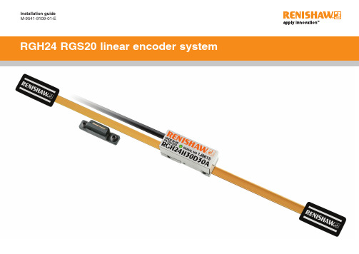
Installation guideM-9541-9109-01-EContentsProduct compliance 1 Storage and handling 2 RGH24 readhead installation drawing 3 RGS20 scale installation drawing 4 Scale application 5 End clamps 5 Reference mark and limit switch actuator installation 5 Readhead mounting and alignment 6 Reference mark setup 6 Limit switch 6 Output signals 7 Speed 7 Electrical connections 8 Output specifications 9 General specifications 10 Scale specifications 10Product complianceCRenishaw plc declares that RGH24 complies with the applicable standards and regulations.A copy of the EC Declaration of Conformity is available on request.FCC complianceThis device complies with part 15 of the FCC Rules. Operation is subject to the following two conditions: (1) This device may not cause harmful interference, and (2) this device must accept any interference received, including interference that may cause undesired operation.The user is cautioned that any changes or modifications not expressly approved by Renishaw plc or authorised representative could void the user’s authority to operate the equipment.This equipment has been tested and found to comply with the limits for a Class A digital device, pursuant to part 15 of the FCC Rules. These limits are designed to provide reasonable protection against harmful interference when the equipment is operated in a commercial environment.This equipment generates, uses, and can radiate radio frequency energy and, if not installedand used in accordance with the instruction manual, may cause harmful interference to radio communications. Operation of this equipment in a residential area is likely to cause harmful interference in which case the user will be required to correct the interference at his own expense.NOTE: This unit was tested with shielded cables on the peripheral devices. Shielded cables must be used with the unit to ensure compliance.Further informationFurther information relating to the RGH24 encoder range can be found in the RGH24 systemData sheet (L-9517-9677). This can be downloaded from our website /encoder and is also available from your local representative. This document may not be copied or reproduced in whole or in part, or transferred to any other media or language, by any means without the written prior permission of Renishaw. The publication of material within this document does not imply freedom from the patent rights of Renishaw plc.DisclaimerRENISHAW HAS MADE CONSIDERABLE EFFORTS TO ENSURE THE CONTENT OF THIS DOCUMENT IS CORRECT AT THE DATE OF PUBLICA TION BUT MAKES NO WARRANTIESOR REPRESENTATIONS REGARDING THE CONTENT. RENISHAW EXCLUDES LIABILITY, HOWSOEVER ARISING, FOR ANY INACCURACIES IN THIS DOCUMENT.The use of this symbol on Renishaw products and/or accompanying documentation indicates that the product should not be mixed with general household waste upon disposal. It is the responsibility of the end user to dispose of this product at a designated collection point for waste electrical and electronic equipment (WEEE) to enable reuse or recycling. Correct disposal of this product will help to save valuable resources and prevent potential negative effects on the environment. For more information, please contact your local waste disposal service or Renishaw distributor.The packaging of our products contains the following materials and can be recycled.REACH regulationInformation required by Article 33(1) of Regulation (EC) No. 1907/2006 (“REACH”) relating to products containing substances of very high concern (SVHCs) is available at:/REACHStorage and handlingRGS20 – 100 mmNOTE: Ensure self-adhesive tape is on outside of bend.Minimum bend radiusOperatingStorageSystem +55 °C 0 °CHumidity95% relative humidity (non-condensing) to EN 60068-2-78N-heptane Propan-2-ol CH 3CHOHCH Acetone3COCH 3Methylated SpiritsChlorinated SolventsRGH24 readhead installation drawing Dimensions and tolerances in mm*Dimensions measured from substrate.†Required nominal 0.8 gap can be set using blue readhead spacer (supplied) positioned between readhead and actuator when positioning/fixing the actuator.‡The recommended thread engagement is 5 mm. The recommended tightening torque is between 0.5 and 0.7 Nm.RGS20 scale installation drawing(with reference mark actuator)Dimensions and tolerances in mmNOTE: The surface roughness of the scale mounting surface must be ≤3.2 Ra. The parallelism of the scale surface to the axis of motion (readhead rideheight variation) must be within 0.05 mm.Bolted reference mark actuator shown(Bolted limit switch actuator shown(Optional epoxy mounted reference mark actuator(A-9531-0250)Optional epoxy mounted limit switch actuator(A-9531-0251)RGS20 scale installation drawing (with limit switch actuator)Dimensions and tolerances in mmScale applicationThe scale applicator A-9541-0124 is designed specifically for use with the RGH24 readheadsand RGS20-S scale. Use applicator A-9541-0305 when installing RGS20-P scale.Allow scale to acclimatize to installation environment prior to installation.Thoroughly clean and degrease the substrate using recommended solvents (see 'Storage and handling').Allow substrate to dry before applying scale. Mark out ‘START’ and ‘FINISH’ points for the scale on the axis substrate. Ensure that there is room for theend clamps (see ‘RGS20 scale installation drawing’). Mount the appropriate scale applicator to the readhead mounting bracket using M2.5 screws. Place the shimsupplied with the readhead between the applicator and substrate to set the nominal height. NOTE:Scale applicator can be mounted either way round to enable easiest orientation for scale installation.Move axis close to scale start position, leaving enough room for the scale to be inserted through theapplicator as shown below. Begin to remove the backing paper from the scale and insert scale into the applicator up to the ‘ST ART’ point(as shown). Ensure backing tape is routed under the splitter screw.End clampsA-9523-4015 is an end clamp kit designed to be used with Renishaw RGS scale.IMPORTANT: End clamps should be used to ensure positional stability of the scale and reference mark repeatability.NOTE: End clamps can be mounted before or after readhead installation.Ensure that excess glue is wiped away from scale as it may affect the readhead signal level.The end clamp features two small regionsof contact adhesive. These will temporarily hold the end clamp in position while the glue cures. Remove the backing tapefrom either side.Remove the lacquer coating from the last15 mm of each end of the scale with a knife and clean with one of the recommended solvents (see ‘Storage and handling’).Immediately position end clamp over theend of the scale. Allow 24 hours at 20 °C for full cure.Thoroughly mix up a sachet of glue(A-9531-0342) and apply a small amount to the underside of the end clamp.Remove applicator and, if necessary, adhere remaining scale manually. Apply firm finger pressure via aclean lint-free cloth along the length of the scale after application to ensure complete adhesion.Clean the scale using Renishaw scale wipes (A-9523-4040) or a clean, dry, lint-free cloth. Fit end clamps (see ‘End clamps’ section).Allow 24 hours for complete adhesion of scale before fitting the reference mark or limit magnet.‘ST ART’ pointSlowly and smoothly move the applicator through the entire axis of travel, ensuring the backing paper ispulled manually from the scale and does not catch under the applicator.Reference mark and limit switch actuator installationScrew mounted or adhesive mounted reference mark and limit switch actuators are available.Refer to RGH24 readhead installation drawing and RGS20 scale installation drawing for actuator positioning.Direction of scale application STARTFor reliable operation, the set-up LED should be GREEN when readhead is moved along the full axis travel.The JST version of the RGH24 has an LED repeater signal that can be used in cases where the LED is not visible.*Remote LED will continuously flash Red when signal <20%Readhead mounting and alignmentMounting bracketsThe bracket must have a flat mounting surface, enable conformance to the installation tolerances, allow adjustment to the rideheight of the readhead, and be sufficiently stiff to prevent deflection or vibration of the readheadduring operation. For easier installation, adjust the roll and yaw of the bracket with respect to the axis of readhead travel before the RGH24 is attached. This can be done with a clock gauge and a precision square.Readhead set-upT o set nominal rideheight, position readhead spacer with ‘L’ shaped aperture under the optical centre of thereadhead to allow normal LED function during set-up procedure. Ensure that the scale, readhead optical window and mounting face are clean and free from obstructions.NOTE: Ensure readhead fixing screws are tightened to 0.5 Nm-0.7 Nm.IMPORTANT: The RGH24 range does not incorporate a separate Alarm ‘E’ signal. Low signal is indicated by a 3-state output of the line driver channels.Reference mark set-upT o ensure unidirectional repeatability, the reference mark requires phasing with the scale in the direction of normal datuming operation.A reference pulse is output in both directions, but repeatabilty is guaranteed only in the phased direction.Ensure readhead is set up correctly with a green LED indication over the full length of travel and that the reference mark actuator is fitted correctly.NOTE: It is recommended that a datum procedure is performed as part of any power-up sequence to ensure the correct datum position is recorded.NOTE: Reference mark output is synchronised with the incremental channels, giving unit of resolution pulse width.Phasing procedureLimit switchA limit switch signal is output when the readhead sensor passes over the magnetic actuator.NOTE: RGH24 readheads are available with reference mark or limit switch detection.Select output at order.NOTE: Limit switch output is not available with analogue RGH24, or options 60, 61 and 62 of the digital RGH24.Output signalsRGH24 D, X, Z, W, Y, H, I, O RS422A digitalRGH24B 1Vpp analogue10 pin JST plug(Termination code Z)15 pin D type plug (Termination code D, L)9 pin D type plug (Termination code A)SpeedDigital readheadsNon-clocked output readheadsNOTE: Maximum speeds of clocked output variants assume 3 m maximum cable length and minimum 5 V supply at readhead connector.Analogue readheadsRGH24B – 4 m/s (−3dB)Clocked output readheadsThe RGH24W, Y , H, I and O readheads are available with a variety of different clocked outputs.Customers must ensure they comply with the lowest recommended counter input frequency.Remote LED driver outputsJST connector version allows for remote monitoring of readhead status.Electrical connections* IMPORTANT: The outer shield should be connected to the machine earth (Field Ground). The inner shield should be connected to 0 V . Care should be taken to ensure that the inner and outer shields are insulated from each other. If the inner and outer shields are connected together, this will cause a short between 0 V and earth, which could cause electrical noise issues.Recommended signal terminationDigital outputs - RGH24D, X, Z, W, Y, H, I and OAnalogue output - RGH24BV 0 V 1 V 2+V 0 V 1 V 2−ΩStandard RS422A line receiver circuitryCapacitors recommended for improved noise immunity.150 Ω+–Output specificationsGeneral specificationsPower supply 5 V ±5%120 mANOTE: Current consumption figures refer to unterminated readheads.For digital outputs a further 25 mA per channel pair (e.g. A+, A−) will bedrawn when terminated with 120 Ω.For analogue outputs a further 20 mA will be drawn when terminatedwith 120 ΩPower from a 5 V dc supply complying with the requirements for SELVof standard IEC BS EN 60950-1.Ripple200 mVpp @frequency up to 500 kHz maximum.Temperature Storage−20 °C to +70 °COperating0 °C to +55 °CHumidity95% relative humidity (non condensing) to EN 60068-2-78Sealing IP40Acceleration Operating500 m/s2, 3 axesShock Non-operating1000 m/s2, 6 ms, ½ sine, 3 axesVibration Operating100 m/s2 max @ 55 Hz to 2000 Hz, 3 axesMass Readhead11 gCable34 g/mCable8 core, double shield, maximum diameter 4.4 mmFlex life >20 × 106 cycles at 20 mm bend radiusThe RGH24 series readheads have been designed to the relevant EMC standards, but must be correctly integrated to achieve EMC compliance. In particular, attention to shielding arrangements is critical. Renishaw recommends the use of a double screened cable to connect RGH24 JST as used in the cable variants of the RGH24Scale specificationsScale type RGS20-S Reflective gold plated steel tape with protective lacquer coating.Adhesive backing tape allows direct mounting to the machine substrate.RGS20-P Reflective gold plated steel tape with tough polyester coating forapplications using harsh solvents.Adhesive backing tape allows direct mounting to the machine substrate. Scale period20 µmLinearity RGS20-S±3 µm/mRGS20-P±5 µm/mScale length Up to 50 m (>50 m by special order)Form(H × W)RGS20-S0.2 mm × 6 mm (includes adhesive)RGS20-P0.3 mm × 6.3 mm (includes adhesive)Substrate materials Metals, ceramics and composites with expansion coefficientsbetween 0 and 22 µm/m/°C(steel, aluminium, Invar, granite, ceramic etc.)Expansion coefficient Matches that of substrate material when scale ends are fixed byepoxy mounted end clampsEnd fixing Epoxy mounted end clamps (A-9523-4015) using 2 part epoxyadhesive (A-9531-0342)Scale end movement typically <1 µm up to +40 °CTemperature Operating−10 °C to +120 °C.Minimum installation10 °CStorage−20 °C to +70 °C.Humidity95% relative humidity (non-condensing) to EN 60068-2-78Renishaw plcNew Mills, Wotton-under-Edge, Gloucestershire GL12 8JR United KingdomT +44 (0)1453 524524F +44 (0)1453 524901E ***************For worldwide contact details,please visit our main website at/contactPart no.: M-9541-9109-01-EIssued: 03.2019 *M-9541-9109-01*RENISHAW HAS MADE CONSIDERABLE EFFORTS TO ENSURE THE CONTENT OF THIS DOCUMENT IS CORRECT A T THE DATE OF PUBLICATION BUT MAKES NO WARRANTIES OR REPRESENTATIONS REGARDING THE CONTENT. RENISHAW EXCLUDES LIABILITY , HOWSOEVER ARISING, FOR ANY INACCURACIES IN THIS DOCUMENT .© 2001-2019 Renishaw plc. All rights reserved.Renishaw reserves the right to change specifications without notice.RENISHAW and the probe symbol used in the RENISHAW logo are registered trade marks of Renishaw plc in the United Kingdom and other countries. apply innovation and names and designations of other Renishaw products and technologies are trade marks of Renishaw plc or its subsidiaries.All other brand names and product names used in this document are trade names, trade marks or registered trade marks of their respective owners.。
SIR-20雷达操作手册 中文版
SIR-20 操作手册美国劳雷工业有限公司第二章二维测量参数设置 (1)2.1: System Parameter Setup 系统参数设置 (1)Create Folders 创建文件夹 (2)Set Program Defaults 设置缺省值 (2)Set working directories 设置工作目录 (3)2.2: Setting Up your System for 2D Data Collection 二维测量 (4)Projects and Profiles: How the SIR-20 Collects Data 项目 (4)The File Header 文件头 (4)Collection Parameters 采集参数设置 (5)2.3: Data Collection Methods 数据采集方法 (7)Survey Wheel Controlled Collection 测量轮控制测量 (7)Position/Range信号位置/时间窗口 (14)Gain增益 (15)Filters and Stacking滤波和叠加 (17)During Collection 数据采集 (18)Time-Based (Free run continuous) Data Collection 连续测量数据采集 (18)Point Mode Data Collection 点测 (19)第二章二维测量参数设置SIR-20地质雷达系统启动后,计算机桌面上有几个radar程序的快捷方式。
基本程序包括数据采集程序SIR-20,现场处理程序RADAN。
图5 SIR-20 桌面SIR-20地质雷达系统有五个快捷方式:RADAN,SIR-20,SS Linescan, Structure Scan, and Optical Scan。
RADAN是后处理程序,其它四个为相互独立的数据采集程序,SIR-20为通用数据采集程序,后三个程序专门采用高频天线检测混凝土结构(详细信息参考第四章)。
Sirios LED 急救灯安装与操作手册说明书
Installation and Operation Manual Sirios LED Emergency Lighting (CG-S)Sirios LED Emergency Lighting - Installation & Operating instructionsStep by step Mounting InstructionsSafety InformationObserve the national safety rules and regulations to prevent accidents as well as the safety instructions included in these instruction lea et.2179SummaryLedpositionApplication Exit Sign Antipanic Escape Route Open (Λ)Closed (ΙΙ)Best*GoodBest**GoodGood Best**** Better uniformity on sign ** Bigger covering area,*** Longer distance in smaller heights, lower illuminance diversity along the route path Open position (Λ)Route, up 4m heightClosed position (II)for Anti-panicSirios LED Emergency Lighting 1-05-255E - Installation & Operation manual 63Conformity with standardsConforms to: EN 60 598-1, EN 60 598-2-22 and DIN EN 1838. Developed, manufactured and tested in accordance with DIN EN ISO 9001.Brief description / Scope of applicationThe emergency light Sirios LED CG-S is suitable for operation on CEAG emergency lighting systems acc. to EN 50 172, DIN VDE 0100-718 and E DIN VDE 0108-100 . The advanced switching and monitoring mode is only available in combination with CEAG CG-S technology.Addressing / Single luminaire monitoringLED converter contolled by a V-CG-S2 monitoring module having 20 addresses for individualmonitoring of luminaire correct operation. Before tting the luminaire, the individual addressing will have to be performed. To do so, the desired address (1-20) is set on the address switch by means of a suitable screw driver. If the luminaire should not be monitored, the code 0/0 has to be selected.Address switch 1 (Tens)000 (1)...2Address switch 2 (Units)012...1...Luminaireaddress Monitoring off 12...11...20Disposal / RecyclingWhen disposing of faulty equipment, observe the valid regulations for recycling and disposal. Plastic parts are marked with the appropriate symbols.Inspection/Maintenance/RepairObserve the valid regulations for theinspection, maintenance and repair of electrical equipment!The light source contained in this luminary shall only be replaced by the manufacturer or his service agent or a similar quali ed person, replacement order code is O-SLED-STRIPE.Sirios LED Emergency Lighting 1-05-255E - Installation & Operation manual Installation / OperationFor the mounting and operation of electrical apparatus, the respective national safetyregulations as well as the general rules ofengineering will have to be observed!Safety NotesŸThe luminaire shall only be used for itsintended purpose and in an indamaged and perfect condition!ŸOnly genuine Eaton spare parts may be used for replacement and repair!ŸWhen working on the emergency luminaire rst the system must be blocked, batteryoperation must be interrupted and mains must ŸPrior to its initial operation, the luminaire will have to be checked in accordance with the instructions as per section ‘Installation’!ŸCarry out the marking of the emergency luminaire:ŸAssign the circuit, the luminaire no. and ID no. and enter them.ŸThe manual log book shall be performed in compliance with the national regulations. It is not applicable by automatical log book!ŸAny foreign matter shall be removed from the luminaire prior to its initial operation!ŸObserve the national safety rules andregulations for prevention of accidents as well operating instructions marked withT echnical DataInput voltage:Power: O-SLED-CG-S Enclosure material:Colour of enclosure: Luminous uxphiE/phiNenn at the end of rated operating time: Supply terminals: Insulation class:Degree of protection acc. to EN 60529: Admissible amb. temperature Lamp:Weight:220-240 V AC, 50/60 Hz, 176 V - 275 V DC33mA AC / 18mA DC PC white100%plug-in terminal 2.5 mm²II IP4200+0C to +40C24 white LED 1.5W 0,77 KgEaton is a registered trademark.All other trademarks are property of their respective owners.© 2015 EatonAll Rights Reserved Printed in EUPublication No. 1-05-255E October 2015Eaton Industries Manufacturing Electrical Sector EMEA Route de la Longeraie 71110 Morges, Switzerland Eaton.euCooper Univel S.A.Thessalonikis 8860134 Katerini, Greece DimensionsSirios171mm357mm153mmSirios weatherproof base。
TL-AC300 V1.0用户手册2.0.0
为普联技术有限公司注册商标。本手册提及的所有商标,由各自所有人拥有。 本手册所提到的产品规格和资讯仅供参考,如有内容更新,恕不另行通知。除非有特殊约定,本手册仅作为 使用指导,所作陈述均不构成任何形式的担保。 Nhomakorabea目录
艾默生SR-20说明书
目录SR-20组成部分 (2)SR-20简要介绍 (3)开始操作介绍 (3)显示内容介绍 (4)设置 (8)SR-20管线探测 (10)探头定位 (15)菜单及其设置 (19)SR-20 组成部分图 1: SR-20 组成部分串行端口USB 接口 序列号标签 图例说明电池仓注:USB/串行端口仅用于上载新软件。
显示屏 按键区 手柄 扬声器折叠夹天线立柱上部天线 折叠铰点导向天线 下部天线SR-20 简要介绍开始操作介绍安装/更换电池把SR-20倒过来会找到用于提供电力的电池仓。
首先逆时针转动旋钮打开仓盖,按照正负极标记装入电池,盖上仓盖,轻压顺时针转动旋钮。
图2: 电池仓当启动SR-20时,它会花几秒钟来检测电池电量。
如果电池用完,它会显示为“empty”(空)。
折叠天线杆开始操作前,展开折叠天线至铰点处锁住。
当完成定位工作时,按下红色释放按钮,折叠天线以便于存放。
注:当进行定位操作时,避免使下部天线在地面拖行。
因为这样会导致噪音信号,影响定位结果,并最终可能导致天线损坏。
释放按钮图3: 折叠天线杆和释放按钮SR-20 探测模式SR-20 有三种截然不同的探测模式. 它们是:1. 有源探测模式,通过信号发生机,选定一个频率施加于一段较长的导体上,用于探测具有导电性能的管道、管线或电缆。
2. 无源探测模式,用于探测50Hz或60Hz的电力电线,或无线电频率探测。
3. 发射探头探测模式,用于探测非金属管道、沟渠或隧道内的发射探头或者不能被前两种模式探测到的地方。
注:两种管线探测模式─有源和无源,除了所用的频率不同外,其他原理都是一样的。
在无源模式下不会用到信号发射机。
显示内容介绍对于初次使用定位仪的用户或经验丰富的用户,都同样可以轻易上手使用SR-20。
SR-20提供许多先进的特性和参数,使得大多数复杂的定位工作变得非常容易。
此外,当你在不复杂的环境下完成一些最基本的定位工作时,这些特性和参数还可以关闭或隐藏,从而使得显示内容一目了然。
- 1、下载文档前请自行甄别文档内容的完整性,平台不提供额外的编辑、内容补充、找答案等附加服务。
- 2、"仅部分预览"的文档,不可在线预览部分如存在完整性等问题,可反馈申请退款(可完整预览的文档不适用该条件!)。
- 3、如文档侵犯您的权益,请联系客服反馈,我们会尽快为您处理(人工客服工作时间:9:00-18:30)。
SIRveyor SIR-20 用户手册劳雷公司2005年1月目录第一部分:启动和基本项目的安装 (1)1.1 系统启动 (1)1.2 软件和新项目设置 (1)1.3 创建新项目 (5)1.4 打开已存在的项目文件 (12)1.5 运行当前的项目文件 (14)第二部分:数据采集格式 (15)2.1 单一的二维文件格式 (15)2.2 数据采集——三维文件格式 (17)2.3做超三维分析需补充的数据采集步骤 (22)附录A:SIRveyor 技术规格 (23)附录B:SIRveyor 用于数据采集的电源和配置 (25)附录C:采样道排列形式 (29)附录D:装好的SIR-20配置 (31)附录E:创建和编辑宏命令 (37)附录F:在SIR-20上使用通用雷达 (39)附录G:普通材料的介电值和术语集 (41)术语集 (42)附录H:数据处理和成像 (44)附录I:SIRveyor 命令按钮 (46)第一部分:启动和基本项目的安装SIRveyor SIR 20 是有2 个硬件道(天线),4个记录道的高性能地质雷达(GPR)系统。
SIRveyor被用来记录、处理和显示地下特征的剖面和三维图象(如果有三维格式采集的资料)。
该系统配有标准的GSSI天线,能被用于各种应用领域,来解决复杂的地下探测问题和构造探测问题。
SIRveyor允许我们:●采集:由一个天线采集到4道的数据由两个天线采集到4道的数据二维格式的单一剖面三维格式数据的采集●野外处理数据●复查和显示二维剖面或三维格式的野外数据,1.1 系统启动1、把选择的电源连接到SIRveyor SIR-20设备上(当只有掌上电脑电池时系统不运行)2、接通计算机;开关位于以太网连接器后边计算机右部的后面。
3、一旦计算机接通,并且SIR-20已插入,则系统就运行。
4、过几分钟,显示器灯将闪两下,然后就保持稳定了。
更多的信息请查附录B。
1.2 软件和新项目设置先打开RADAN系统信息屏幕,就可找到软件版本和序列号。
该屏幕将在30秒后消失,或点击鼠标左键跳到下一屏幕。
为了采集数据,特别设置了SIRveyor 的快捷键。
虽然RADAN软件屏幕和SIRveyor 的屏幕好像相同,但两者的配置是不同的,因而数据不能通过RADAN 快捷键采集。
目录、长度和数据库的系统设置这些命令使你能安装系统,以便在新地区收集数据。
如果你希望继续做先前的项目,就跳到1.4部分打开存在的项目文件。
否则,就按以下步骤进行。
第一步是设置数据目录。
对每个工区或每项工作创建新的数据目录,会使管理数据更容易。
应该先指定一个单独的输出目录路径,以便让软件将已处理的数据放到该输出目录。
1、设置文件信息选择视窗>Customize(用户自选)。
2、选择目录表,然后设置源目录和输出目录。
注释:Customize ——用户自选Directories ——目录Appearance ——状态,外观Database ——数据库Linear Units ——长度Source ——源目录Output ——输出目录OK——确定Cancel——取消Apply——应用Help ——帮助3、选择长度列表,然后设置想要的单位。
注释:Customize ——用户自选Directories ——目录Appearance ——状态,外观Database ——数据库Linear Units ——长度Vertical ——垂直Horizontal ——水平OK——确定Cancel——取消Apply——应用Help ——帮助METER ——米CM ——厘米INCH——英寸FOOT——英尺YARD——码4、选择数据库列表,然后点击要选择的临时数据库标记选项。
注释:No Markers Informaion ——无标记的信息Temporary Markers Database——临时标记数据库Permanent Markers Database——永久标记数据库Customize ——用户自选Directories ——目录Appearance ——状态,外观Database ——数据库Linear Units ——长度OK——确定Cancel——取消Apply——应用Help ——帮助5、一旦正确地设置了这些软件参数,就继续到下一节完成新项目的设置。
注释:Step 1 Create New Project ——第一步创建新项目Step 2 Create New Project file ——第二步创建新项目文件3D Project File ——三维项目文件Step 3 Data Collection Mode ——第三步数据采集模式Step 4 Data Collection Parameters ——第四步数据采集参数Step 5 Attach Macro ——第五步附加宏Step 6 Setting Review –System Initialization ——第六步设置复查——系统初始化Step 7 Run ——运行 Save & Stop——保存和停止 Delete & Stop——删除和停止1.3 创建新项目第一步:创建新项目为了开始一个新项目,选择FILE菜单下的New 或点击New Collect。
对一个新的三维项目,必须点击Create 3D File ,请参阅2.2节。
第二步:创建新项目文件1、进入项目文件名。
在合适的输入框内键入唯一的项目文件名,然后点击Save保存。
如果已经存在一个相同文件名的文件,则将提醒你取代老的文件或改变为新文件名。
(注释:位于该窗口底部的Collect Data Files命令框会自动检查,它不能被关闭。
)注释: Create New Data Collection Project——创建新的数据采集项目“1. Type project name”——键入项目名“2. Save”——保存2、在点击Save后,项目信息对话框就会打开,见下图.注释:Project Information ——项目信息“1. Check path”——核对路径“2. Change ,if required”——如果需要,就改变“3. All white fields are optional”——所有空白的方框都是任选的“4. Click OK”——点击OK3、该窗口允许我们检查文件在计算机里被保存的位置(路径).也允许设置测量时间,题目,和任何能在处理或解释期间起帮助作用的注释.这些区域(字段)都是可选择的.4、点击OK, Select Data Collect Mode 对话框就打开了.第三步:数据采集模式数据采集模式对话控制着数据被采集的方式。
●Free Run ——连续采集数据● Point Mode——点测● Survey Wheel ——测量轮● Gosling ——参见附录F注释:测量轮除了为三维成像采集数据外,还必须与构造扫描系统一起来使用。
Free Run:数据是基于设置在文件宏中的每秒扫描时间和次数来采集的。
即使处于稳定状态,只要叉杆开关是压下的,天线就总是不断进行采集。
Point Mode:随着选择叠加,扫描数是被单个收集的。
Survey Wheel:数据是基于测量轮的旋转而采集的,测量轮的旋转是随着你设置的采样率而变化的。
不旋转,就不采集。
Calibrate:为了在不规则界面上得到准确的数据采样,就需对测量轮能够进行校正。
Enable GPS log:将GPS数据(通用雷达数据)录制在笔记本计算机中的一个文件中,该文件是与GPR.dzt文件分开的。
来自GPR数据的扫描数被输出,然后把它并入GPS数据。
Calibrate Survey Wheel:为了把测量轮调节到草地或不平坦地带那样的不同测量界面,要求必须对测量轮做标定。
在理想条件下(平坦、光滑界面、新轮子)的标定数字如下。
若不正确,你的距离计算将是较差的(较远的)。
标定测量轮:1.点击标定按钮.在测量界面上测量一个固定距离,至少10英尺或3米。
注释:Select Positioning System——选择定位系统Calibrate ——标定2.把天线的中心放在0位置(只要在起点和停止点是相同的,天线的任何部分都可以采用)。
(注释:Survey Wheel Calibration——测量轮标定)3.点击开始.测量标定线开始完成4.把天线拉出该距离的长度.5.点击完成.6.点击Save保存.7.一旦标定过程完成,每单位的信号数就出现了.8.重复几次以确信结果..第四步:设置数据采集参数.图注释:Data Collection Parameters ——数据采集参数 Transmit Rate ——发射率数据采集参数(该图用于二维采集。
三维采集的参见2.2节)1——Configuration Type(排列类型):天线选择方式有默认设置,用户设置。
在项目头设置天线名。
2——Configuration Name (排列名称):为多级记录道数据采集选择记录道,同时选择多级天线。
()3——# of Channels:为采集数据所选择的道号。
4——Samples/scan:每次扫描所采集到的样品数,这些选择要预先设置。
5——Scans/second:每秒钟采集到的扫描数,它控制着系统的速度。
6——Dielectric Constant:被测量的介电值控制着深度刻度的精确度。
7——Scans/unit(ft or m):使用测量轮时的数据采样率。
8——Unit/mark:当使用测量轮时,每X英尺/米所自动插入的标号。
9——Antenna Name(天线名):为多道数据采集选择天线。
10——Transmitter(发射器):为每道采集到的数据,指定发射器的位置。
11——Receiver(接收器):为每道采集到的数据,指定接收器的位置。
12——用于发射器/接收器(天线)1的连接器。
13——用于发射器/接收器(天线)2的连接器。
14——对每道采集的数据,道列表中显示出了发射器和接收器的排列形式。
数据采样:特征4到特征8使你能指定数据采集的采样率。
基于测量类型,目标,和测量模式(自由式,点测式或测量轮式),这些特征可以被调节到最适合项目目的。
排列(配置)类型:一张天线频率列表,可用来识别选那一个天线来做测量。
排列(配置)名称(选择天线):在数据采集中天线数目的预先选择。
发射率:固定在100KHz.道的选择(天线名/发射率):可以有1,2或4个数据道,一个或两个天线。
一个天线包括一个T(发射器)和一个R(接收器)。
对每个数据道,你选择一个T 和一个R。
附录C中提供了一些例子。
对使用一个天线的,系统自动默认单道操作。