KLM524G工业级千兆24口以太网交换机说明书
赫斯曼交换机型号说明书
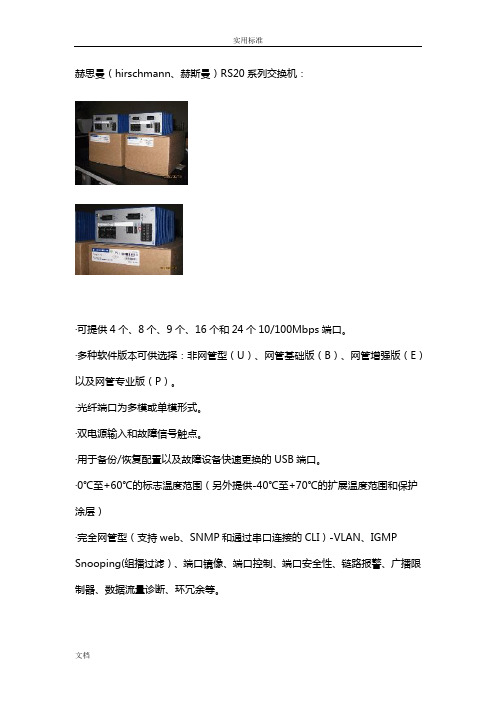
赫思曼(hirschmann、赫斯曼)RS20系列交换机:·可提供4个、8个、9个、16个和24个10/100Mbps端口。
·多种软件版本可供选择:非网管型(U)、网管基础版(B)、网管增强版(E)以及网管专业版(P)。
·光纤端口为多模或单模形式。
·双电源输入和故障信号触点。
·用于备份/恢复配置以及故障设备快速更换的USB端口。
·0℃至+60℃的标志温度范围(另外提供-40℃至+70℃的扩展温度范围和保护涂层)·完全网管型(支持web、SNMP和通过串口连接的CLI)-VLAN、IGMP Snooping(组播过滤)、端口镜像、端口控制、端口安全性、链路报警、广播限制器、数据流量诊断、环冗余等。
如需了解产品具体价格或技术参数,请联系我们。
常用型号:全电口RS20-0400T1T1SDAEHC (4×RJ45,0℃至+60℃标准温度,网管增强型)RS20-0400T1T1SDAPHC (4×RJ45,0℃至+60℃标准温度,网管专业版)RS20-0800T1T1SDAEHC (8×RJ45,0℃至+60℃标准温度,网管增强型)RS20-0800T1T1SDAPHC (8×RJ45,0℃至+60℃标准温度,网管专业版)RS20-1600T1T1SDAEHC (16×RJ45,0℃至+60℃标准温度,网管增强型)RS20-1600T1T1SDAPHC (16×RJ45,0℃至+60℃标准温度,网管专业版)RS20-2400T1T1SDAEHC (24×RJ45,0℃至+60℃标准温度,网管增强型)RS20-2400T1T1SDAPHC (24×RJ45,0℃至+60℃标准温度,网管专业版)多模光纤RS20-0400M2T1SDAEHC (3×RJ45 1×SC,0℃至+60℃标准温度,网管增强型)RS20-0400M2T1SDAPHC (3×RJ45 1×SC,0℃至+60℃标准温度,网管RS20-0400M2M2SDAEHC (2×RJ45 2×SC,0℃至+60℃标准温度,网管增强型)RS20-0400M2M2SDAPHC (2×RJ45 2×SC,0℃至+60℃标准温度,网管专业版)RS20-0800M2M2SDAEHC (6×RJ45 2×SC,0℃至+60℃标准温度,网管增强型)RS20-0800M2M2SDAPHC (6×RJ45 2×SC,0℃至+60℃标准温度,网管专业版)RS20-0800M4M4SDAEHC (6×RJ45 2×ST,0℃至+60℃标准温度,网管增强型)RS20-0800M4M4SDAPHC (6×RJ45 2×ST,0℃至+60℃标准温度,网管专业版)RS20-1600M2T1SDAEHC (15×RJ45 1×SC,0℃至+60℃标准温度,网管增强型)RS20-1600M2T1SDAPHC (15×RJ45 1×SC,0℃至+60℃标准温度,网管专业版)RS20-1600M2M2SDAEHC (14×RJ45 2×SC,0℃至+60℃标准温度,网管增强型)RS20-1600M2M2SDAPHC (14×RJ45 2×SC,0℃至+60℃标准温度,网管专业版)RS20-2400M2M2SDAEHC (22×RJ45 2×SC,0℃至+60℃标准温度,网RS20-2400M2M2SDAPHC (22×RJ45 2×SC,0℃至+60℃标准温度,网管专业版)单模光纤RS20-0400S2T1SDAEHC (3×RJ45 1×SC,0℃至+60℃标准温度,网管增强型)RS20-0400S2T1SDAPHC (3×RJ45 1×SC,0℃至+60℃标准温度,网管专业版)RS20-0400S2S2SDAEHC (2×RJ45 2×SC,0℃至+60℃标准温度,网管增强型)RS20-0400S2S2SDAPHC (2×RJ45 2×SC,0℃至+60℃标准温度,网管专业版)RS20-0800S2S2SDAEHC (6×RJ45 2×SC,0℃至+60℃标准温度,网管增强型)RS20-0800S2S2SDAPHC (6×RJ45 2×SC,0℃至+60℃标准温度,网管专业版)RS20-1600S2S2SDAEHC (14×RJ45 2×SC,0℃至+60℃标准温度,网管增强型)RS20-1600S2S2SDAPHC (14×RJ45 2×SC,0℃至+60℃标准温度,网管专业版)RS20-2400S2S2SDAEHC (22×RJ45 2×SC,0℃至+60℃标准温度,网管增强型)RS20-2400S2S2SDAPHC (22×RJ45 2×SC,0℃至+60℃标准温度,网管专业版)赫思曼(hirschmann、赫斯曼)MS4128-L2P系列交换机:·4个100Mbps插槽形式。
ProSafe JFS524 24端口Ethernet交换机用户指南说明书

Conmutador Ethernet de 24 puertos ProSafe JFS524Paso 3. Comprobar el estadoMódemopcionalPaso 1. Conectar el equipoJFS524Router opcionalEquipoServidorInternetEncendido ApagadoIndicador de alimentaciónActividad (intermitente)Sin conexión (apagado)Indicadores de puertos superioresGuía de instalaciónPaso 2. Conectar la alimentaciónIndicadores de puertos inferioresEnlace (encendido)Conexión a 100 Mbps Conexión a 10 MbpsSeptiembre de 2012Este símbolo se ha colocado conforme a la directiva 2002/96 de la UE sobre Residuos de Aparatos Eléctricos y Electrónicos (la Directiva RAEE). Si se tuviera que desechar este producto dentro de la Unión Europea, se tratará y se reciclará de conformidad con lo dispuesto en las leyes locales pertinentes, en aplicación de la directiva RAEE.NETGEAR, el logotipo de NETGEAR y Connect with Innovation son marcas comerciales o marcas comerciales registradas de NETGEAR, Inc. o sus filiales en Estados Unidos y otros países. La información contenida en el documento puede sufrir modificaciones sin previo aviso. El resto de marcas y nombres de productos son marcas comerciales o marcas comerciales registradas de sus respectivos titulares. © NETGEAR, Inc. Todos los derechos reservados.Sólo para uso en interior en todos los países de la UE y Suiza.Para la declaración de conformidad de la UE completa, visite /app/answers/detail/a_id/11621/.Condiciones : Con el fin de mejorar el diseño interno, el funcionamiento y la fiabilidad, NETGEAR se reserva el derecho de realizar modificaciones del producto descrito en el presente documento sin previo aviso. NETGEAR no asume responsabilidad alguna derivada del uso o la aplicación de los productos o circuitos descritos en el presente documento.EspecificacionesEspecificaciones DescripciónInterfaz de redVeinticuatro (24) puertos 10/100 Mbps Ethernet RJ-45 10BASE-T o 100BASE-TXCable de red Cable Ethernet categoría 5 (Cat 5) o superior Puertos24AC (alimentación)100-240VAC 50-60Hz, 1.2A máx., localizado para el país de venta Consumo de energía 9.4W máx.Peso1,43Kg (3,15 libras)Dimensiones(anchura x profundidad x altura)330 mm x 169 mm x 43 mm12,99 pulg. x 6,65 pulg. x 1,69 pulg.Temperatura de funcionamiento 0–50° C (32–122° F)Humedad de funcionamiento Humedad relativa 10%–90%, no condensada Cumplimiento con las normas electromagnéticas CE Clase A, FCC Clase A, VCCI Clase 1, C-Tick Clase A, CCCNormativas de seguridadMarca CE, comerciales listadas en UL (UL 60950-1), CB, CCCServicio técnicoUna vez instalado el dispositivo, busque el número de serie en la etiqueta del producto y regístrelo en https:// .Debe registrar su producto antes de poder usar el soporte telefónico de NETGEAR. NETGEAR recomienda registrar su producto en su sitio web NETGEAR. Para actualizaciones del producto y soporte web, visite .。
全网管控交换机用户手册说明书

全网管控交换机用户手册REV 2.00大连网月科技开发有限公司版权声明版权所有2006-2014,网月科技开发有限公司,保留所有权利。
使用本产品,表明您已经阅读并接受了EULA 中的相关条款。
如有变更,恕不另行通知。
遵守所生效的版权法是用户的责任。
在未经网月科技开发有限公司明确书面许可的情况下,不得对本文档的任何部分进行复制、将其保存或引进检索系统;不得以任何形式或任何方式(电子、机械、影印、录制或其他可能的方式)进行商品传播或用于任何商业、赢利目的。
网月科技开发有限公司拥有本文档所涉及主题的专利、专利申请、商标、商标申请、版权及其他知识产权。
在未经网月科技开发有限公司明确书面许可的情况下,使用本文档资料并不表示您有使用有关专利、商标、版权或其他知识产权的特许。
此处所涉及的其它公司、组织或个人的产品、商标、专利,除非特别声明,归各自所有人所有。
前言感谢您使用网月科技开发有限公司的全网管控交换机(以下文本中简称本产品)。
本产品是网月科技开发有限公司自主开发的二层智能以太网交换机,提供了多个千兆或万兆以太网端口,支持VLAN、端口镜像、防ARP欺骗、DHCP保护等功能,可以通过Web界面方式进行管理。
本产品针对目前局域网中出现的安全问题,提供了802.1x、Guest VLAN、防ARP欺骗、防蠕虫病毒、防MAC地址攻击、三元绑定等一系列安全特性,并且提供了可视化的WEB操作界面,通过简便操作,即可以有效防御ARP欺骗、DOS攻击及蠕虫攻击;交换机当中提供的多种VLAN功能,采用VLAN方式划分网络体系能够让管理员更加方便的管理企业网络,而VLAN网络灵活的扩展能力也让企业网络规模在不断扩大的同时不会出现网络混乱的情况,VLAN网络所具有的控制广播风暴能力让企业网络资源的性能得到大幅度提高,并且VLAN网络还具有管理简单,安全性高的特点。
同时本产品还支持DHCP保护功能,开启功能之后可以手动指定允许通过的DHCP服务的IP及MAC地址信息,非法的DHCP服务器会被交换机阻断掉,良好的解决酒店,出租屋等复杂环境的DHCP分配问题。
友讯PS2024G 24端口千兆三层POE交换机使用说明书

User manualPS2024G24Port Gigabit Layer3PoE SwitchInstallation manual introductionThe Product installation manual mainly describes PS2024GPoE switch hardware features,installation methods,and precautions during the installationThis manual includes the following chapters:Chapter1:Product Introduction.Briefly describes the basic features,Detailed hardware&software specifications of the switch and the appearance details.Chapter2:Product Installation.Guide the switch hardware installation methods and precautions.Chapter3:Hardware Connections.Guide the connection between switches and other devices and precautions.Chapter4:Packaging and product usage suggestions.Chapter1:Product Introduction1.1Products descriptionPS2024G is managed PoE switch for security transmission andWIFI coverage,meet the need of PoE power supply for WIFI AP,IP-camera,WIFI bridge,IP phones and other types ofequipment.New generation of high-performance hardwareand software platforms are used,providing flexible,cost-effective full Gigabit access and uplink ports,complete securitymechanisms,improved ACL/QoS strategy and rich VLANcapabilities.It is easy to manage and maintain,meet the users'requirements for network equipment easy to manage,highsecurity and low cost.Support Apollo Cloud platform.It issuitable for network access,aggregation and core applicationsin campus,hotel and enterprise campus.1.2Product FeaturesFull Gigabit Port241000Mbps RJ45ports(support PoE power supply)with4 Gigabit SFP ports,Data transmission is not jammed.Broadcom chip,the performance is more stable and powerfulRealtek high-performance chip can greatly improve network data processing rateConvenient operation·AI VLAN mode:Separating1-8ports from each other,caneffectively restrain network storm and improve networkperformance.·AI Extend mode:Designed for monitoring applicationscenarios,1-8ports support250meters long distance powersupply.·AI PoE mode:automatically check,reboot the device whilefind it fake dead·AI QoS mode:video data first,more fluent transmissionSupport Apollo Cloud Platform One-stop ManagementSupport cloud platform for resource visualization management of switches and downloaded PD devices,make operation and maintenance management easy1.3product specificationHardware SpecificationsInput100-240V/50-60Hz Dimension440mm×320mm×44mm (L×W×H)Software Specifications1.4AppearanceFront PanelIncluding indicators,RJ45port,DIP switch,RST button,SFP port, CONSOLE port,as shown belowindicatorPS2024G The indicator working status is shown asthe following tablePS2024G The indicator working status is shown asthe following tableAI power supply:Detect PD,power failure and restart dead equipment✧RJ45PortPS2024G with2410/100/1000Mbps PoE port,allports support IEEE802.3af and IEEE802.3at standardWhen the switch mode of operation is CCTV mode,1-8port can support250meters power supply✧SFP PortPS2024G provides4Gigabit SFP optical ports(SFP1, SFP2),can be inserted into the Gigabit SFP module✧RST ButtonWhen the switch is powered on,press the buttonwith the needle to release the device and enter therestarting state.When the SYS lamp restarts,thedevice restarts.When the switch is powered on,press and hold the button for more than5s to release the button and enter the reset state.When SYS is re-lit,the device is reset successfully✧Console portConsole port used to connect to computer or otherterminal to manage or configure the switch.Back PanelIncluding:power socket,power switch,groundterminal✧Power socketA100-240VAC50/60Hz power receptacle foraccommodating the supplied power cord✧Ground terminalPlease use the grounding wire to prevent lightning.To avoid product lightning strikes and extendproduct lifeChapter2Hardware connection2.1RJ45port connectionConnect the RJ45port of the switch and the corresponding network device via cables,the POE power supply function of the switch is default enabled on the downlink port of the switch, which can be used for IEEE802.3af or IEEE802.3at standards powered devices such as APs,bridges,and network camerasNote:When the switch connected workstations,servers,routers or other ethernet devices the cable length should be within100 meters;The Auto-MDI/MDIX ethernet interface is enabled by default.Category5,the standard network cable or crossover cable can be used for Ethernet connection.Do not connect the RJ45port to the phone line2.2SFP Port connectionPS2024G SFP port only support Gigabit fiber module.Recommended use of standard SFP module productsThe process of installing a fiber module on a switch is asfollows:1、grasp the optic fiber module from the side,insert itsmoothly along the SFP port slot until the optic fiber module and switch are in close contact;2、confirm the Rx and Tx ports of the fiber module whenconnecting,insert one end of the fiber into the Rx and Txports correspondingly,ensure that the Tx and Rx ends of the interface are connected correctly and the other end of thefiber is connected to another device;3、please check the corresponding indicator light statusafter power on.If the light blinking that the link is properlyconnected,if the light is off,the link is failure,please check the line to confirm that the corresponding equipment isenabled.Note:DO NOT excessive bending fiber,the radius of curvatureshould not be lessthan10cm;Ensure the cleanliness of the fiber surface;Please DO NOT look directly into the optical fiber connector with your eyes as this may cause eye injury2.3Check before power onCheck whether the outlet power supply meets the switchspecifications;Check the power,switches,racks and other equipment have been properly grounded;Check whether the switch and other network devices areconnected properly2.4Device initializationThe switch automatically initializes when the power switch is turned on.Indicator will appear the following situation:After the power is turned on,the power indicator remains on, the other indicator is off at this time;After about1second,all lights except for the power light turn on for about35seconds and then turn off;when the SYS light goes flashing,the system runs normallyPort LEDs indicates the connection status of each port,indicating that the switch has started to work normallyChapter3Installation3.1Installation PrecautionsNote:To avoid improper use of equipment damage andpersonal injury,please observe the following precautions⏹Installation safety precautions●The power should be kept off during the installation,whilewearing anti-static wrist,and to ensure well touch betweenanti-static wrist and skin to avoid potential safety hazard;●The switch just works normally when it is powered by thecorrect power supply.Make sure that the power supplyvoltage matches the voltage indicated by the switch●Before powering on the switch,make sure that the powercircuit is not overloaded,which may affect the normaloperation of the switch and even cause unnecessarydamage●To avoid the risk of electric shock,do not open the casewhile the switch is working.Do not open the case evenwhen it is not powered●Before cleaning the switch,unplug the switch from thepower cord and do not wipe it with wet cloth.Do not wash it with liquid⏹⏹AltitudeProducts with this logo are only for safe use in areas below 2000m altitude⏹Dust-proofDust on the switch surface will cause electrostaticadsorption,poor contact of the metal contacts.Althoughthe device itself has done some measures in anti-static,but when the static electricity exceeds a certain intensity,it will still cause fatal damage to the electronic components onthe internal circuit board.In order to prevent static electricity from affecting thenormal operation of the equipment,please note thefollowing:1.Regular dust,keep the indoor air clean;2.Make sure the equipment is well grounded to ensuresmooth transfer of static electricity⏹Electromagnetic interferenceElectromagnetic interference have an impact on the device capacitance,inductance and other electronic components by capacitance,inductive coupling,impedance couplingand other conductive,in order to reduce the adverse effects caused by electromagnetic interference,please note thefollowing:1.Power supply system to take the necessary anti-gridinterference measures;2.Switches should be far away from high-frequencyhigh-power,high-current devices,such as wirelesstransmitters;3.If necessary,take electromagnetic shielding measures⏹Lightning protectionWhen a lightning strike occurs,a strong current will begenerated in an instant cause fatal damage to electronicequipment.To achieve better lightning protection,pleasenote the following:1.Make sure the rack and the ground to maintain goodcontact;2.Make sure the power outlet is in good contact with theearth;3.Reasonable wiring,to avoid the internal sense ray;4.Outdoor wiring,it is recommended to use the signallightning protection device⏹Installation desk requirementRegardless of whether the switch is installed in a rack or on another horizontal workbench,be aware of the following:1.Make sure the rack or workbench is stable,strong,andcan withstand at least5.5Kg weight;2.Make sure the rack has a good cooling system,ormaintain good indoor ventilation;3.Make sure the rack is well grounded,the power outletand switch are within1.5metersPrepare tools for installationYou may need to use a screwdriver during installation, electrostatic wrist strap,fiber optic cable and other tools to prepare your own3.2Installation methodPS2024G supports desktop mounting and rack mount.:1、Check rack grounding and stability;2、Install the two L-brackets in the accessory on each side ofthe switch panel and secure with the screws provided in the accessory3、place the switch in an appropriate place in the rack and be supported by the bracket.Screw the L-shaped bracket to the guide groove fixed on both ends of the rack to ensure that the switch is stable and horizontally installed on the rack.Note:Good grounding rack is anti-static equipment,anti-leakage, lightning protection,anti-jamming important guarantee,so to ensure that the rack ground wire properly installed;Installation equipment within the rack from the bottom up, to avoid overload installation;Avoid placing other heavy objects on switch to avoidaccidents;Ensure heat dissipation and air circulation.3.3Web LoginStep1、In the normal operation of the device,connect the computer to the switch's RJ45port by network cablesStep2、Manually changed the computer IP address to192.168.254.X(X is2~254),subnet mask is255.255.255.0Step3、Open computer's browser,type192.168.254.1in the address box,hit the Enter keyStep4、Enter the default username and password“admin”and then click LoginStep5、Entered the switch web management interfacesuccessfully when you see picture as below,you canbegin to configure the switchChapter4:Packaging and product usage suggestions4.1Open the package carefully check the following list4.21.the2.3.to4.water from entering the fuselage through the casing, resulting in damage to the machine;5.Please turn on the power after the line connection is completed;6.When the product is powered on,please do not plug or unplug the cable except for special circumstances.7.Do not use the switch in places with excessive dust and electromagnetic radiation.Do not use the switch in a place with high temperature and no ventilation;8.Please do not place heavy objects on the switch to avoid accidents;9.According to the IEEE802.3AF/AT standard,the transmission distance can reach100meters by using Category5or above wires;10.When connecting a switch to multiple PDs,be careful not to exceed the maximum output power of the switch POE.11.It is recommended to use the switch indoors.It is recommended to add a waterproof box when using it outdoors.12.Considering that the network cable is too long may result in inaccurate data detection.AI Extend and AI PoE cannot be used at the same time.Note:The pictures in the manual are for reference only, whichever is subject to the actual product.。
Linksys SR2024 24-Port Gigabit 交换机用户说明书
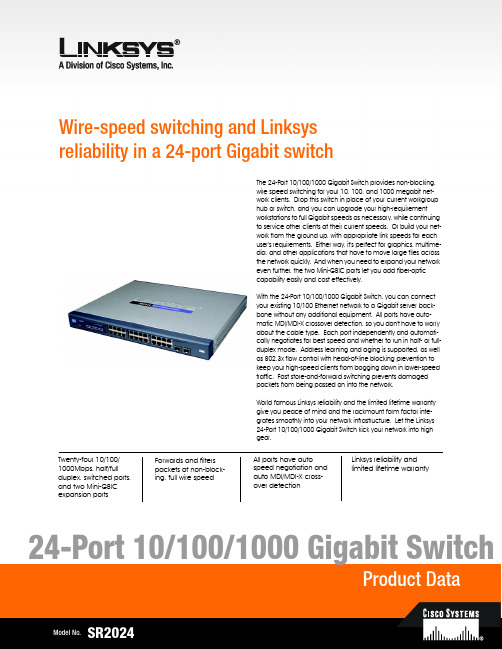
Wire-speed switching and Linksys reliability in a 24-port Gigabit switchTwenty-four 10/100/1000Mbps, half/full duplex, switched ports, and two Mini-GBIC expansion portsLinksys reliability and limited lifetime warrantyForwards and filters packets at non-block-ing, full wire speedAll ports have autospeed negotiation and auto MDI/MDI-X cross-over detectionThe 24-Port 10/100/1000 Gigabit Switch provides non-blocking, wire speed switching for your 10, 100, and 1000 megabit net-work clients. Drop this switch in place of your current workgroup hub or switch, and you can upgrade your high-requirement workstations to full Gigabit speeds as necessary, while continuing to service other clients at their current speeds. Or build your net-work from the ground up, with appropriate link speeds for each user's requirements. Either way, it's perfect for graphics, multime-dia, and other applications that have to move large files across the network quickly. And when you need to expand your network even further, the two Mini-GBIC ports let you add fiber-optic capability easily and cost effectively.With the 24-Port 10/100/1000 Gigabit Switch, you can connect your existing 10/100 Ethernet network to a Gigabit server back-bone without any additional equipment. All ports have auto-matic MDI/MDI-X crossover detection, so you don't have to worry about the cable type. Each port independently and automati-cally negotiates for best speed and whether to run in half- or full-duplex mode. Address learning and aging is supported, as well as 802.3x flow control with head-of-line blocking prevention to keep your high-speed clients from bogging down in lower-speed traffic. Fast store-and-forward switching prevents damaged packets from being passed on into the network.World famous Linksys reliability and the limited lifetime warranty give you peace of mind and the rackmount form factor inte-grates smoothly into your network infrastructure. Let the Linksys 24-Port 10/100/1000 Gigabit Switch kick your network into high gear.Features•24 RJ-45 ports for 10BASE-T/ 100BASE-TX/1000BASE-TX con-nections•Supports half duplex and full duplex modes auto-negotia-tion for all ports.•Auto MDI/MDI-X support on all ports for easy cable detec-tion•Efficient MAC Address learn-ing engine supports up to 8K MAC Addresses •Provides store-and-forward forwarding scheme.•Standard width and mounting kit (included) make it easy to be installed into a rack •Two mini-GBIC ports for easy expansion to other mini-GBIC equipped switchesLinksysA Division of Cisco Systems, Inc.18582 Teller AvenueIrvine, CA 92612 USAE-mail:************************************Web:Linksys products are available in more than 50 countries, supported by 12 Linksys Regional Offices throughout the world. For a complete list of local Linksys Sales and Technical Support contacts, visit our Worldwide Web Site at .Package Contents•One 24-Port 10/100/1000 Gigabit Switch •One AC Power Cord•One User Guide with Registration Card •One Set of Rack Mounting brackets24-Port 10/100/1000 Gigabit SwitchSpecificationsModel Number SR2024Standards IEEE 802.3, 802.3u, 802.3x, 802.3abPorts24 RJ-45 10/100/1000 + 2 Mini-GBIC portsCabling Type Category 5e or betterLEDs System, 1 through 24EnvironmentalDimensions432 mm x 45 mm x 349 mm(W x D x H)(17.01" x 1.75" x 13.74")Unit Weight7.98 lb. (3.62 kg)Power Input110-120VAC, 100WCertifications FCC Class B, CEOperating Temp.32ºF to 122ºF (0ºC to 50ºC)Storage Temp.-40ºF to 158ºF (-40ºC to 70ºC)Operating Humidity20% to 95%, Non-CondensingStorage Humidity5% to 95%, Non-CondensingSpecifications are subject to change without notice. Linksys and EtherFast are registered trademarks of Cisco Systems, Inc. Other brands and product names are trademarks or registered trademarks of their respective holders. Copyright © 2003 Cisco Systems, Inc. All rights reserved.SR2024-DS-80508A-KO。
金浪 24口全千兆管理型交换机说明书

¾ 符合符合 IEEE802.3、IEEE802.3u、IEEE 802.3ab 标准;
¾ 主机背板带宽可达 48G ¾ 存储--转发体系结构
¾ 24 个 10/100/1000M 自适应端口或 22 个 10/100/1000MB 自适应端口+2 个 1000M 光电复用端口
¾ 8K 的 MAC 地址 ¾ 每一个端口都支持地址学习功能 ¾ 支持自动线序交叉功能(Auto-MDIX) ¾ 支持广播和多播数据包的控制 ¾ 支持 IP+MAC+PORT 绑定,防御 ARP 攻击。 ¾ 支持上联端口配置,其他端口自动隔离 ¾ 支持广播风暴控制,可有效控制各种广播数据包的转发数率,避免广播风暴。 ¾ 支持 ARP 防护端口 ARP 攻击报警提示 ¾ 支持网关 ARP 攻击检测。 ¾ 支持 WEB、带外 RS232 管理 ¾ 支持 DHCP 客户端协议。 ¾ 可通过 HTTP、XMODEM 进行系统软件升级,。 ¾ 内置优质开关电源,稳定可靠 ¾ 1U 全钢外壳,支持标准 19 英寸机架安装
当端口工作在 100M 或 1000M 全双工状态时,相对应的 LED 指示灯为绿色常亮。 4) Power 指示灯(电源指示灯)
它的位置在面板的最左边,交换机接上电源后,此指示灯为红色常亮。如果指示灯不亮,检查 是否连接好了电源。
后面板
交换机后面板有—个电源接口。电源工作范围:18 0-260V~50Hz-60Hz。
全千兆管理型交换机 使用说明书
1
物品清单
小心打开包装盒,检查包装盒里应有的配件: 一台交换机 一根交流电源线 一根串口线 一本用户手册 两个 L 型支架如果发现包装盒内产品有所损坏或者任何配件短缺的情况,请及时和当地经销商联系。
[网络交换机具体应用] 24口网络交换机
![[网络交换机具体应用] 24口网络交换机](https://img.taocdn.com/s3/m/ab9b3a4f52d380eb63946d4b.png)
[网络交换机具体应用] 24口网络交换机网络交换机具体应用两台电脑共享上网设置系统是WINDOWS XP的在设置共享的时候非常简单,右键点击“网上邻居”,选择“属性”,就看到了“网络连接”界面,在这个界面的左栏最上方,有一个“网络任务”的小窗口,在这个窗口下有“设置家庭或小型办公网络”,我们的网络设置就从这里开始。
在进行网络设置之前,我们首先要把两台电脑的网卡都装好,并且确认驱动程序已经安装,当然,网线也要先连上,而且两台电脑都要打开,进入操作系统,为什么网络还没有设置就先连网线呢?等会儿大家就明白了。
两台机器通过交叉网线连接好了以后,我们就可以开始网络设置了,首先我们要设置的是主机,也就是所谓的“服务器”。
点击“设置家庭或小型办公网络”,会出现“网络安装向导”提示窗口,里面都是一些网络安装向导的注意事项,点击两次“下一步”按钮后会出现“网络安装向导”提示窗口。
由于我们配置的是主机,所以在这里选择第一个选项,也就是“这台计算机直接连到Inter,我的网络上的其它计算机通过这台计算机连接到Inter”,然后继续点击“下一步”,出现选择窗口,选择一个正确的Inter连接,因为主机中有两块网卡,因此相对应也有两个Inter连接,一个连接到ADSL网络,另一个连接到家庭局域网,如果实在分不清楚的话,可以先到“控制面板/网络连接”下看一看便知。
另外,如果您的ADSL MODEM是USB接口的话,这里应该只有一个连接,会省去您选择的麻烦。
下面的几个步骤可以不去管它,一路按“下一步”就可以了,直到岀现完成该向导窗口。
到这里,就要向大家介绍一下为什么要在配置之前就把两台机器先用网线连接起来了,如果没有先把两台电脑连接的话,您就需要选择第一个“创建网络安装磁盘”选项了,而且还需要在客户机上运行“网络安装磁盘”里面的程序,很麻烦;如果事先先把网线连好,我们就可以选择“完成该向导。
我不需要在其它计算机上运行改向导”选项。
24口三层交换机安装手册

24口3层交换机安装手册兼容性FCC – A级此设备产生、使用和能辐射无线频率能量,如果按照手册指示安装和使用,可能引起与无线通信的冲突。
它已经通过测试,与计算机设备所要求FCC规则的A级和B级的15部分都相符合。
它可以防止冲突,给商业环境提供一个合理的保护。
在居民区运行此设备可能引起干扰,用户可能需要自己花钱采取措施防止正这些干扰。
您必须注意任何没有经过所负责部门任何修改和更正都无效。
您可以使用非屏蔽的RJ-45接头双绞(UTP)电缆——支持10 Mbps连接的3类或更大,支持100 Mbps连接的5类。
使用50/125 或62.5/125微米的多模光纤电缆,或带有SC-type连接头的9/125微米的单模光纤电缆。
警告: 1. 当操作此装备时,使用一条防静电的皮带或其它适当的方式来防止静电。
2. 当把集线器连接到电源插座时,保证三相插座要有地线,以阻止电磁波的干扰。
加拿大行业标准A级这个数字仪器没有超过来自于此仪器的广播噪音发射的A级限定,在引起干扰的授名为“数字仪器”(通信部的ICES-003)的装置标准中测定。
日本VCCI A 级EC 一致声明——A级这个信息技术装置符合委员会所提出的89/336/EEC要求,接近所有成员国的定律:电磁兼容性,73/23/EEC对某些电器设备电压的限制,修改指示93/68/EEC。
可以参考下面的标准来评估是否符合这些指示:RFI 辐射:l A级限定依据EN 55022:1998l 支持辐射的A级限定依据EN 61000-3-2 1995限定电压波动和在低电压提供系统闪烁依据EN 61000-3-3/1995绝缘:l 产品系列规格依据EN 55024:1998l 静电释放依据EN 61000-4-2:1995(接触放电: ±4 kV, 空气放电: ±8 kV)l 无线电频率磁场依据EN 61000-4-3:1996(80 - 1000 MHz ,1 kHz AM 80% 调制: 3 V/m)l 电的快速/瞬时脉冲依据EN 61000-4-4:1995(AC/DC 电源提供: ±1 kV, 数据/信号线: ±0.5 kV)l 电涌免疫测试依据EN 61000-4-5:1995(AC/DC Line to Line: ±1 kV, AC/DC Line to Earth: ±2 kV)l 由无线电频率引起的对导电干扰的免疫:EN 61000-4-6:19962(0.15 - 80 MHz ,1 kHz AM 80%调制: 3 V/m)l 电源频率磁场免疫测试依据EN 61000-4-8:1993 (1 A/m频率为50 Hz)l 电压倾斜, 短时中断和电压变化免疫测试依据EN 61000-4-11:1994 (>95% 减少@10 ms, 30% 减少@500 ms, >95% 减少@5000 ms)LVDl EN 60950 (A1/1992; A2/1993; A3/1993; A4/1995; A11/1997)Taiwan BSMI Class A警告使用者:这是甲类的信息产品,在居住的环境中使用时,可能会造成射频干扰,在这种情况下,使用者会被要求采取某些适当的对策。
- 1、下载文档前请自行甄别文档内容的完整性,平台不提供额外的编辑、内容补充、找答案等附加服务。
- 2、"仅部分预览"的文档,不可在线预览部分如存在完整性等问题,可反馈申请退款(可完整预览的文档不适用该条件!)。
- 3、如文档侵犯您的权益,请联系客服反馈,我们会尽快为您处理(人工客服工作时间:9:00-18:30)。
KLM524G 千兆4光24电非网管型机架式工业级以太网交换机
●支持14个千兆电+4个千兆SFP光
●符合重工业EN61000-6-2标准
●10/100/1000M,全/半双工,MDI/MDI-X自
适应
●坚固的金属外壳,IP40防护等级
●支持AC/DC220V电源输入
●工业级宽温设计,无风扇设计
产品简述
KLM524G系列是一款非网管全千兆工业以太网交换机,支持24个10/100/1000Base-T(X)电口,4个千兆
SFP扩展槽。
KLM524G遵循工业设计标准,低功耗高效率,采用工业无风扇散热模式,外壳使用铝合金型材,使产品轻巧、坚固、耐腐蚀、抗电磁干扰能力更强,工作温度-40~75℃,标准1U机架式安装,支持85~265V AC/DC 电源输入,提供过流,过压,短路和过热等工业级电源保护,主要用于工业现场控制设备PLC,工控机及其他现场控制设备的高密度连接。
目前该产品广泛应用于智能交通,能源风电,管廊隧道,智能制造等工业恶劣环境。
技术参数
属性KLM524G
接口24个10/100/1000base-T(X)自适应以太网RJ45接口4个千兆SFP扩展槽
以太网口速率和距离1O/1OO/1000M自适应
双绞线最大传输距离100m
光口属性及传输距离单模1310nm,多模850nm;单模20km多模550m(长距离模块可定制)处理类型存储转发
MAC地址表大小8k
背板带宽60Gbps
包转发速率41.7Mpps
包缓冲区大小4Mbit
流控IEEE802.3x流量控制,半/双工背压流量控制
指示灯电源指示:PWR,接口灯指示:CPU、SPEED、link/ACT
电源输入电压:AC/DC85~265V可选支持失电告警功能
支持电源防反接保护
工业凤凰端子接线
工作环境工作温度:-40℃~+75℃
储存温度:-40℃~85℃
相对湿度:5%~95%无凝露
安装方式1U机架式安装
外形尺寸宽×高×深:482.8×44×220mm 防护等级IP40防护等级,无风扇设计MTBF400000小时
质保期5年
符合标准IEEE802.3:CSMA/CD IEEE802.3i:10base-T IEEE802.3u:100base-T IEEE802.3ab:1000base-T IEEE802.3z:1000base-LX IEEE802.3x:流量控制
EMI电磁干扰度测试
EMC IEC61000-4-2(ESD)±8kV(contact)±15kV(air)
IEC61000-4-3(RS)10V/m(80MHz~2GHz)
IEC61000-4-4(EFT)Power Port:±4kV;Data Port:±2kV
IEC61000-4-5(Surge)Power Port:±2kV/DM±4kV/CM;Data Port:±2kV IEC61000-4-6(CS)3V(10kHz~150kHz);10V(150kHz~80MHz)
IEC61000-4-16(共模传导)30V(cont.)300V(1s)
安装尺寸
订购型号
产品型号规格参数
KLM524G16个10/100/1000M电口,电压:AC/DC85~265V可选
MKLM524G-4GF16个10/100/1001M电口,4个1000M SFP扩展槽,电压:AC/DC85~265V可选。