VICKERS比例阀技术使用操作细节资料
vickers电磁换向阀技术参数
Vickers电磁换向阀技术参数概述Vickers电磁换向阀是一种常用于液压系统中的控制元件,用于控制液压流体的流向。
它由电磁线圈、阀芯和阀座组成,通过控制电磁线圈的通断来控制阀芯的运动,从而实现液压流体的换向操作。
本文将详细介绍Vickers电磁换向阀的技术参数,包括工作压力、流量、温度范围、电磁线圈参数等。
技术参数工作压力Vickers电磁换向阀的工作压力范围通常为0-350 bar。
在实际应用中,根据具体的液压系统要求,可以选择不同工作压力范围的电磁换向阀。
流量Vickers电磁换向阀的流量范围通常为0-1000 L/min。
流量是指单位时间内通过阀芯的液压流体的体积。
在选择电磁换向阀时,需要根据液压系统的流量需求来确定合适的电磁换向阀流量。
温度范围Vickers电磁换向阀的温度范围通常为-40°C至+120°C。
温度是指电磁换向阀所能耐受的环境温度范围。
在实际应用中,需要根据液压系统的工作环境温度来选择合适的电磁换向阀。
电磁线圈参数Vickers电磁换向阀的电磁线圈参数包括电压、功率和连接方式。
•电压:通常有12V、24V、110V和220V等选项。
根据实际应用需求和电源供应情况,选择合适的电压。
•功率:通常根据电磁线圈的电压和电流来计算,单位为瓦特(W)。
•连接方式:通常有螺纹连接和插接连接两种方式。
螺纹连接适用于需要固定安装的场合,插接连接适用于需要频繁更换的场合。
阀芯类型Vickers电磁换向阀的阀芯类型有多种选择,常见的有直动式和间接式。
•直动式阀芯:阀芯直接由电磁线圈控制运动,结构简单,响应速度快。
•间接式阀芯:阀芯通过驱动杆与电磁线圈相连,结构复杂,但具有较大的工作力和行程。
在选择阀芯类型时,需要根据具体的液压系统要求和应用场景来确定。
阀座材料Vickers电磁换向阀的阀座材料通常选用耐磨损、耐腐蚀的材料,如铜合金或不锈钢。
阀座材料的选择需要考虑液压流体的性质和工作环境的要求。
VICKERS电磁阀DG4V-3-2C-M-P7-H-7-52技术资料
VICKERS电磁阀DG4V-3-2C-M-P7-H-7-52技术资料VICKERS电磁阀DG4V-3-2C-M-P7-H-7-52安装注意:1、安装时应注意阀体上箭头应与介质流向一致。
不可装在有直接滴水或溅水的地方。
电磁阀应垂直向上安装;2、电磁阀应保证在电源电压为额定电压的15%-10%波动范围内正常工作;3、电磁阀安装后,管道中不得有反向压差。
并需通电数次,使之适温后方可正式投入使用;4、电磁阀安装前应彻底清洗管道。
通入的介质应无杂质。
阀前装过滤器;5、当电磁阀发生故障或清洗时,为保证系统继续运行,应安装旁路装置。
VICKERS电磁阀DG4V-3-2C-M-P7-H-7-52使用:VICKERS电磁阀出来的先导油控制主换向阀阀芯的移动,使工作泵的来油进入动臂油缸实现动臂上升。
比例先导减压阀的输出压力越大,控制主换向阀阀芯的位移越大,主换向阀通过的流量越大,动臂上升的速度越快。
当操作手柄拉至极限位置时,手柄中的限位电磁铁通电,手柄在极限位置被吸合。
动臂以最大的速度上升,当升至动臂上位限位开关所限定的位置时,操作手柄限位电磁铁断电,手柄自动恢复到中位,动臂就可保持在所限定的位置。
在动臂上升的过程中,若需要动臂在某一位置停留,则需将操作手柄退回中位。
VICKERS电磁阀主要用在电气液压伺服系统中作为执行元件(见液压伺服系统)。
在伺服系统中,液压执行机构同电气及气动执行机构相比,具有快速性好、单位重量输出功率大、传动平稳、抗干扰能力强等特点。
另一方面,在伺服系统中传递信号和校正特性时多用电气元件。
因此,现代高性能的伺服系统也都采用电液方式,伺服阀就是这种系统的必需元件。
VICKERS电磁阀DG4V-3-2C-M-P7-H-7-52在工业生产及设备维护过程中, 经常会进行线圈匝间短路故障的测试。
但测试方法都不理想, 给生产、维护带来了诸多不便。
设计是通过感知振荡器来检测线圈是否有短路情况,当被测线圈无匝间短路时, 感知振荡器起振, 有正弦波输出, 再通过耦合电路将正弦波信号耦合输出给正常指示电路;如果线圈中有两匝或两匝以上之间发生短路时, 该短路线圈将构成闭合回路, 并在磁路中产生高阻尼, 使振荡器停振, 报警电路立即进行声、光报警。
丹福斯 Vickers KB比例阀概述说明书
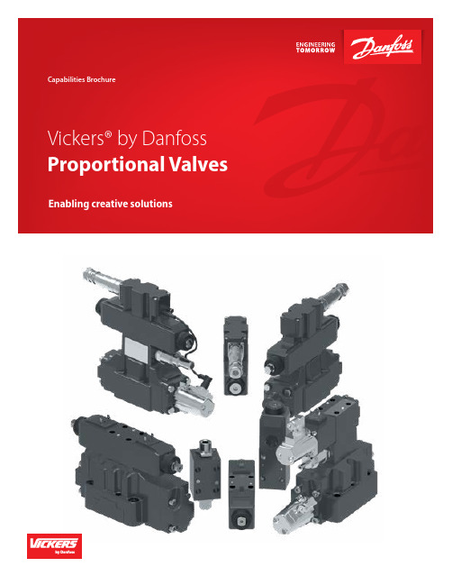
Demanding applications call for Vickers by DanfossWith a wide range of markets serviced, our KB proportional valves are enabling truly creative solutions.As technology continues to improve, so does the engineering Danfoss builds into its proportional valves. Vickers KB proportional valves are manufactured, sold, and supported throughout the world with the high quality you expect from Danfoss. 1. Control function - direction, flow, and pressure2. Performance levels - standardhigh, and servo3. Onboard electronics – with (KB model) and without (K model)4. Complete size range – D03-D10 (NG6-NG32)5. Wide variety of supportingelectronics Integrated amplifiers mean“plug and play”Integrated amplifiers are factorypreset and eliminate any adjustmentof gain, dead-band compensation,or dither required for separatecard and valve combinations. Plusthey eliminate the need for fieldadjustments and separately wired andmounted. Replacement valves can befitted without adjusting or changingthe control signals.New design means newapplicationsWith Vickers by Danfoss, KBproportional valves design engineersnow have a new generation ofintegrated valves that redefine andexpand industrial application designcapabilities. Vickers proportionalvalves are much easier to install thanprevious models using separate driveamplifiers. The only electrical inputsrequired are a power supply and acommand signal.Built to lastFor durability, you cannot beata KB proportional valve. Theamplifier is housed in a durablemetal enclosure, sealed againstenvironmental contaminates such ascutting fluid spray, water, and fluidwash down. Seven-pin electricalmating connectors are supplied asstandard. They are reliable, rugged,and provide easy access for testequipment.Consistency of quality is assured withthe KB proportional valve. Each valve/amplifier combination is tested andcalibrated as a total assembly with avariation of less than 5% from valveto valve. You can trust Vickers KBproportional valves to do the job asspecified and perform consistentlyand reliably for years.Rubber press Entertainment Primary metal Die castingProportional valve application matrixThe matrix to the right provides guidance for many industrial applications. Locate anapplication similar to yours, then read therecommended Valve Performance Level(Standard, High, or Servo Performance) atthe top and the ISO Valve Size (Size 3, 5, 7, 8,or 10) on the right side.The matrix uses “Frequency Response”as the primary determinant forvalve performance. This is not theonly parameter of importance in allapplications, but it does serve as a goodfirst reference.For example:Sawmill Setworks applications generallyrequire Servo Performance type valves. Thevalve size could be either a Size 5 or a Size 7depending upon the flow requirements of theapplication.500(1892) 400(1514) 300(1135) 200(757) 100(378) 70(265) 50(189) 40(151) 3020(76) 10(37) 7543210.7(2.6) 0.5(1.9) 0.40.3(1.1)0.2(0.76) Frequency at 90°Phase Lag (Hz) 35 7 8 10F l o w a t 1000 P S I P r e s s u r eG P M (L P M ) I S O V a l v e S i z e Valve Performance LevelPress Paper machine Machine toolCeramic pressSpecifications, features, and benefits of KB prop valvesOBE proportional valve comparisonFlow capability Frequency response GPM(US) LPM 0Hz Red fonts mean Danfoss’ product superiority over competitors.* Digital OBE valve: KBD(T)G4V, KBDG5V, KBFDG5V, KBX(C)G, KBCG, *IP65 on limited number of familitiesProportional directional valve with on-board-electronics (OBE)Proportional directional valve without on-board-electronics (Non-OBE)Amplifier (Euro card mounting)Amplifier (Din-plug mounting)Functional module (Din-rail mounting)Others Notes:A - with 2 rampsB - A plus on-board command inputsC - B plus additional 2 rampsD - C plus PID moduleE - A plus strip guidance module F- A plus CNC adaptation moduleProportional pressure relief valve familyEHST-3KBCG-6KCG-8Proportional pressure reducing valve familyKBX(C)G-6KBX(C)G-8KX(C)G-6KX(C)G-8 Proportional throttle slip-in valve family – with main stage LVDT feedbackValvistor – proportional throttle slip-in cartridge valve familyProduct and system descriptionBenefitsHigh bending speed, with precise control of bending depth, results in greater productivity. The design of the safety system blocks reduces production and maintenance costs.In order to improve productivity and quality, it is critical that the plasticizing process be precisely controlled. It requires accurate, repeatable, and smooth transition from velocity into pressure regulation. It is also imperative to achieve smooth, quick, and precise clamping movement.Product and system descriptionServo performance proportional valves K(B)S/ HDG and high performance K(B) FDG families with tailored spool design, are the answer for meeting the extremely demanding injection and clamping control requirements. They have an excellent dynamic capability of closed loop control on pressure, position, and velocity. BenefitsReduced cycle time and costs, with improved process control. One valve with a specially designed spool does all five critical controls of plasticizing, injection speed, holding pressure, decompression, worm return, and suck-back pressure. The “valve enable” feature on the KB line can be used to easily achieve interlock function.Highly accurate positioning, repeatability of machining cycles, and precise synchronization control of cylinders during the closing movement of the bending tool, are prerequisites of the hydraulic control system.By using two K(B)F/SDG4V proportional valves for small tonnage machines, or two K(B) HDG5V valves for large tonnage machines in closed loops, Vickers valves provide the solution to this very demanding application. System control blocks provide full compliance to safety regulations.Productivity is king. This transformsto the requirements of overallmachine reliability and durability,and precise control, and shortcycle time. Harsh environment isanother challenge for proportionalvalves mounted on the machines;robustness against shock,vibration, EMC, dirt, and moistureis a must.Product and systemdescriptionServo performance proportionalvalves KBS/HDG, with fullyencapsulated OBE (EN90version), provide extremelyreliable protection in conditionof vibrations and shock.Valves with zero lap spool andgrounded spool/sleeve pilotstage are characterized by theirhighdynamic performance— withlow hysteresis and high responsesensitivity— to achieve accuratepositioning control and speedcontrol.BenefitsOnboard Electronics (OBE) valvesfeature “plug and play” to savewiring hassle and tuning time. IP65 & 67 environment protectionprovide “best in industry”protection against moisture tomake sure the proportional valveswork reliably. When coupledwith a Vickers servo cylinder,the proportional valves can bemounted directly onto the cylinderto become a servo actuatorpackage.Wind power turbine control is avery demanding application thatrequires proportional valves tobe extremely reliable and durabledue to the nature of continuousproduction process. At the heartof advanced wind turbines is ahydraulic control system thatcontrols the pitch angle of theturbine blades, hence controllingthe speed and power production.Challenges are closed looppositioning control for precisepitch angle, and low and highambient temperatures in extremelyharsh environments.Product and systemdescriptionCoupled with servo cylinders,Vickers high performanceproportional valves KBFDG providea compact, rugged, and reliablepackage solution.BenefitsDigital Onboard Electronics(OBE) valves feature presetting theparameters with programming,which results better reproducibilityand repeatability. Failsafe featureprevents the equipment frombeing damaged. IP 65 and 67protection ratings mean Vickersvalves provide better resistance tomoisture than any competitors.Primary applicationsPress brake Injection molding machine Sawmill Wind power© Danfoss | Power Solutions | May 2023AD426931590930en-000101Any information, including, but not limited to information on selection of product, its application or use, product design, weight, dimensions, capacity or any other technical data in product manuals, catalogues descriptions, advertisements, etc. and whether made available in writing, orally, electronically, online or via download, shall be considered informative, and is only binding if and to the extent, explicit reference is made in a quotation or order confirmation. Danfoss cannot accept any responsibility for possible errors in catalogues, brochures, videos and other material. Danfoss reserves the right to alter its products without notice. This also applies to products ordered but not delivered provided that such alterations can be made without changes to form, fit or function of the product. All trademarks in this material are property of Danfoss A/S or Danfoss group companies. Danfoss and the Danfoss logo are trademarks of Danfoss A/S. All rights reserved.Danfoss Power Solutions, Nordborgvej 81, 6430 Nordborg, Denmark, Tel. +45 74 88 22 22, Fax +45 74 65 25 80 ,E-mail:****************。
维克斯(Vickers)双泵双梭型交流型油泵系列操作手册说明书
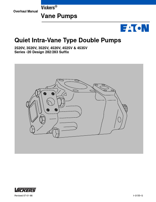
I–3155–SRevised 07-01-86Quiet Intra-Vane Type Double Pumps2520V, 3520V, 3525V, 4520V, 4525V & 4535V Series -20 Design 282/283 SuffixOverhaul ManualVickers ®Vane PumpsTable of ContentsSection PageI.Introduction. . . . . . . . . . . . . . . . . . . . . . . . . . . . . . . . . . . . . . . . . . . . . . . . . . . . . . . . . . . . . . . . . . . . . . . . .A.Purpose of Manual3. . . . . . . . . . . . . . . . . . . . . . . . . . . . . . . . . . . . . . . . . . . . . . . . . . . . . . . . . . . . . . . . . . . . . . . . .B.General Information3II.Description. . . . . . . . . . . . . . . . . . . . . . . . . . . . . . . . . . . . . . . . . . . . . . . . . . . . . . . . . . . . . . . . . . . . . . . . . . . . . . . . . . .A.General4III.Principles of Operation. . . . . . . . . . . . . . . . . . . . . . . . . . . . . . . . . . . . . . . . . . . . . . . . . . . . . . . . . . . . . . . . . . . . . . . . . . . . . . . . . . .A.General4IV.Installation and Operating Instructions. . . . . . . . . . . . . . . . . . . . . . . . . . . . . . . . . . . . . . . . . . . . . . . . . . . . . . . . . . . . . . . . . . . . . . . .A.Installation Drawings5. . . . . . . . . . . . . . . . . . . . . . . . . . . . . . . . . . . . . . . . . . . . . . . . . . . . . . . . . . . . .B.Mounting and Drive Connections5. . . . . . . . . . . . . . . . . . . . . . . . . . . . . . . . . . . . . . . . . . . . . . . . . . . . . . . . . . . . . . . . . . . . . . . . . . . . . .C.Shaft Rotation5. . . . . . . . . . . . . . . . . . . . . . . . . . . . . . . . . . . . . . . . . . . . . . . . . . . . . . . . . . . . . . . . . . . . . . . . . .D.Piping and Tubing5. . . . . . . . . . . . . . . . . . . . . . . . . . . . . . . . . . . . . . . . . . . . . . . . . . . . . . . . . . . .E.Hydraulic Fluid Recommendations5. . . . . . . . . . . . . . . . . . . . . . . . . . . . . . . . . . . . . . . . . . . . . . . . . . . . . . . . . . . . . . . . . . . . . . . . . . . . . .F.Sound Levels6. . . . . . . . . . . . . . . . . . . . . . . . . . . . . . . . . . . . . . . . . . . . . . . . . . . . . . . . . . . . . . . . . . . . . . . . .G.Overload Protection6. . . . . . . . . . . . . . . . . . . . . . . . . . . . . . . . . . . . . . . . . . . . . . . . . . . . . . . . . . . . . . . . . . . . . . . . . . . . . . . . . . .H.Start-Up6V.Service and Maintenance. . . . . . . . . . . . . . . . . . . . . . . . . . . . . . . . . . . . . . . . . . . . . . . . . . . . . . . . . . . . . . . . . . . . . . . . . . .A.Circuit Inspection6B.Adding Fluid to the System6. . . . . . . . . . . . . . . . . . . . . . . . . . . . . . . . . . . . . . . . . . . . . . . . . . . . . . . . . . . . . . . . . .. . . . . . . . . . . . . . . . . . . . . . . . . . . . . . . . . . . . . . . . . . . . . . . . . . . . . . . . . . . . . . . . . . . . . . . . . . . . . . .C.Adjustments6. . . . . . . . . . . . . . . . . . . . . . . . . . . . . . . . . . . . . . . . . . . . . . . . . . . . . . . . . . . . . . . . . . . . . . . . . . . . . . . .D.Lubrication6. . . . . . . . . . . . . . . . . . . . . . . . . . . . . . . . . . . . . . . . . . . . . . . . . . . . . . . . . . . . . . . . . . . . . . . . .E.Replacement Parts6. . . . . . . . . . . . . . . . . . . . . . . . . . . . . . . . . . . . . . . . . . . . . . . . . . . . . . . . . . . . . . . . . . . . . . . . . . . . . . . .F.Product Life7. . . . . . . . . . . . . . . . . . . . . . . . . . . . . . . . . . . . . . . . . . . . . . . . . . . . . . . . . . . . . . . . . . . . . . . . . . . .G.Troubleshooting7VI.Overhaul. . . . . . . . . . . . . . . . . . . . . . . . . . . . . . . . . . . . . . . . . . . . . . . . . . . . . . . . . . . . . . . . . . . . . . . . . . . . . .A.Service Tools8. . . . . . . . . . . . . . . . . . . . . . . . . . . . . . . . . . . . . . . . . . . . . . . . . . . . . . . . . . . . . . . . . . . . . . . . . . . . . .B.Unit Removal8. . . . . . . . . . . . . . . . . . . . . . . . . . . . . . . . . . . . . . . . . . . . . . . . . . . . . . . . . . . . . . . . . . . . . . . . . . . . . . .C.Disassembly8. . . . . . . . . . . . . . . . . . . . . . . . . . . . . . . . . . . . . . . . . . . . . . . . . . . . . . . . . . . . . . . . . . . . . . . . . . . . . . . . . .D.Cleaning9. . . . . . . . . . . . . . . . . . . . . . . . . . . . . . . . . . . . . . . . . . . . . . . . . . . . . . . . . .E.Inspection, Repair and Replacement9. . . . . . . . . . . . . . . . . . . . . . . . . . . . . . . . . . . . . . . . . . . . . . . . . . . . . . . . . . . . . . . . . . . . . . . . . . . . . . . . . .F.Assembly9 VII.Start-Up and Test. . . . . . . . . . . . . . . . . . . . . . . . . . . . . . . . . . . . . . . . . . . . . . . . . . . . . . . . . . . . . . . . . . . . . . . . . . . . . . . . . . .A.Start-Up10. . . . . . . . . . . . . . . . . . . . . . . . . . . . . . . . . . . . . . . . . . . . . . . . . . . . . . . . . . . . . . . . . . . . . . . . . . . . . . . . . . . . . .B.Test102A. Purpose of ManualThis manual describes operational characteristics and over-haul information for fixed and variable delivery inline piston type pumps and motors. The information contained herein pertains to the latest design series.B. General InformationRelated Publications– Service parts information and instal-lation dimensions are not contained in this manual. The parts catalogs and installation drawings listed in Table 1 are avail-able from Vickers.Table 1. Parts and Installation drawingsModel Codes– Variations within each basic model series are covered in the model code. T able 2 is a breakdown of the model codes covering these units. the model code will be stamped into the cover nameplate. If an older design unit is being updated to the new 282/283 design, stamp the new design number on the nameplate. Inquiries should always include the complete unit model code number as stamped on the nameplate.Model Code3520V – 25, 30, 35, 38 3525V – 25, 30, 35, 38 4520V – 42, 50, 60 4525V – 42, 50, 60 4535V – 42, 50, 607Shaft type1–Straight with square key(standard, all models)86–Straight with square key (heavyduty, all models except 2520V)3– Foot mountingTable 2. Model code breakdown3A. GeneralThe double intra-vane pump with a 282/283 suffix is designed to operate at reduced noise levels, but still maintain the same reliability, operating characteristics and service advantages of previous models.All sound reduction in the 282/283 series pump is accomplished within the cartridge kit. The ring, vanes, rotor and plate have been redesigned. The pump housing remains unchanged, thus, existing systems may be upgraded by simply replacing the cartridge kit. Figure 1 shows the basic 282/283 cartridge kit. Note that 12 vanes are assembled into the machined rotor slots. Previous designed models use 10 vanes.Figure 1. -282/-283 basic cartridge kit partsSection III – Principles of OperationA. GeneralThe operating principle of a vane pump is illustrated in Figure 2. A slotted rotor is splined to the drive shaft and turns inside a cam ring. Vanes are fitted to the rotor slots and follow the inner surface of the cam ring as the rotor turns. Centrifugal force and pressure under the vanes hold them out against the cam ring. Pumping chambers are formed between the vanes and the cam ring and are enclosed by the two end plates.The 282/283 series pumps are of a balanced intra-vane design (Figure 2). Outlet pressure is constantly applied to the small intra-vane area of the vane. As the pump vane rotates through the high and low quadrants, outlet pressure is alternately applied to the rest of the under vane area. This varying pressure under the vane reduces wear and increases pump efficiency.Pump delivery can be changed by changing the ring or installing a new cartridge kit. Table 2 shows available delivery options. Cartridge kit part numbers are tabulated in the parts and service drawings (Table 1).Figure 2. Vane Pump Operation45Section IV – Installation and Operating InstructionsA. Installation DrawingsThe installation drawings listed in Table 1 show operating characteristics, installation dimensions and port locations.B. Mounting and Drive ConnectionsCAUTIONPump shafts are designed to be installed in couplings with a slip fit. Pounding can injure the bearings. Shaft tolerances are shown on the installation drawing (Table 1).1. Direct Mounting – A pilot on the pump mounting flange (Figure 3) assures correct mounting and shaft alignment. Make sure the pilot is firmly seated in the accessory pad of the power source. Care should be exercised in tightening the mounting screws to prevent misalignment.2. Indirect drive is not recommended for these pumpswithout Vickers engineering approval.Figure 3. Mounting flange and pilotC. Shaft RotationPumps are assembled for either right hand (clockwise) or left hand (counterclockwise) shaft rotation as viewed from theshaft end.CAUTIONNever drive a pump in the wrong direction of rotation. Seizure will result, necessitating expensive repairs.D. Piping and Tubing1. All pipes and tubing must be thoroughly cleaned before installation. Recommended methods of cleaning are sand blasting, wire brushing, pickling and power flushing with clean solvent to remove loose particles.NOTEFor information on pickling, refer to instruction sheet 1221-S.2. To minimize flow resistance and the possibility of leakage, only as many fittings and connections as are necessary for proper installation should be used.3. The number of bends in tubing should be kept to a minimum to prevent excessive turbulence and friction of oil flow. Tubing must not be bent too sharply. Therecommended minimum radius for bends is three times the inside diameter of the tube.E. Hydraulic Fluid RecommendationsGeneral DataFluid in a hydraulic system performs the dual function of lubrication and transmission of power. It constitutes a vital factor in a hydraulic system and careful selection of it should be made with the assistance of a reputable supplier. Proper selection of fluid assures satisfactory life and operation of system components with particular emphasis on hydraulic pumps. Any fluid selected for use with pumps is acceptable for use with valves or motors.Data sheet I-286 for fluid selection is available from Vickers Technical Publications, Troy, Michigan 48084.Fluid recommendations noted in the data sheet are based on our experience in industry as a hydraulic componentmanufacturer. Where special considerations indicate a need to depart from the recommended fluids or operating conditions, see your Vickers sales engineer.CleanlinessThorough precautions should always be observed to insure that hydraulic system is clean.1. Clean (flush) entire new system to remove paint,metal chips, welding shot, etc.2. Filter each change of fluid to prevent introduction of contaminants into the system.3. Provide continuous filtration of fluid to remove sludge and products of wear and corrosion generated during the life of the system.4. Provide continuous protection of system from entry of airborne contamination by sealing the system and/or by proper filtration of the air.5. During usage, proper fluid filling and servicing of filters, breathers, reservoirs, etc., cannot be over emphasized.6. Thorough precautions should be taken by proper system and reservoir design to insure that aeration of the fluid will be kept to a minimum.F. Sound LevelsAlthough system noise levels can be reduced by modifying pump design, fluid conditions also play a major part in reducing system noise levels.Some of the major factors affecting the fluid conditions that cause the loudest noises in a hydraulic system are:1. Very high viscosities at low start-up temperatures can cause pump noise due to cavitation.2. Running with a moderately high viscosity fluid will impede the release of entrained air. The fluid will not be completely purged of such air in the time it remains in the reservoir before recycling through the system.3. Aerated fluid can be caused by ingestion of air through the pipe joints of inlet lines, high velocity discharge lines, cylinder rod packings or by fluid discharging above the fluid level in the reservoir. Air in the fluid causes a noise similar to cavitation.G. Overload ProtectionRelief valve limit pressure in the system to a prescribed maximum and protect components from excessive pressure. The setting of the relief valve depends on the work requirements of the system.H. Start-UpWith a minimum drive speed of 600 RPM, a pump should prime almost immediately if provision is made to initially purge the air from the system.Failure to prime within a reasonable time may result in damage due to lack of lubrication. The pump housing must be filled with fluid and inlet lines must be tight and free from air leaks. It may be necessary to crack a fitting on the outlet side of the pump to purge air trapped in the system.Section V – Service and MaintenanceA. Circuit InspectionPeriodic inspection of the fluid condition and tube or pipe line connections can save time-consuming breakdowns and unnecessary parts replacement. the following should be checked regularly:1. All hydraulic connections must be kept tight. A loose connection in a pressure line will permit the fluid to leak out. If the fluid level becomes so low as to uncover the inlet pipe opening in the reservoir, extensive damage to the pump can result. In suction or return lines, loose connections permit air to be drawn into the system resulting in noisy and/or erratic operation.2. Clean fluid is the best insurance for long service life. Therefore, the reservoir should be checked periodically for dirt or other contaminants. If the fluid becomes contami-nated, the system should be drained and the reservoir cleaned before new fluid is added.3. Filter elements also should be checked and replaced periodically. A clogged filter element results in a higher pressure drop. This can force particles through the filter which would ordinarily be trapped, or can cause the by-pass to open, resulting in a partial or complete loss of filtration.4. Air bubbles in the reservoir can ruin the pump and other components. If bubbles are seen, locate the source of the air and seal the leak.5. A pump which is running excessively hot or noisy is a potential failure. Should a pump become noisy or over-heated, the machine should be shut down immediately and the cause of improper operation corrected.B. Adding Fluid to the SystemWhen hydraulic fluid is added to replenish the system, it should always be poured through a clean wire screen (200 mesh or finer) or preferably pumped through a 10 micron (absolute) filter.It is important that the fluid be clean and free of any sub-stance which could cause improper operation or wear of the pump or other hydraulic units. Therefore, the use of cloth to strain the fluid should be avoided to prevent lint getting into the system.C. AdjustmentsNo periodic adjustments are required, other than to maintain proper shaft alignment with the driving medium.D. LubricationInternal lubrication is provided by the fluid in the system. Lubrication of the shaft coupling should be as specified by their manufacturers. Coat shaft splines with a dry lubricant (Molycoat or equivalent) to prevent wear.E. Replacement PartsReliable operation throughout the specified operating range is assured only if genuine Vickers parts are used. Sophisti-cated design processes and material are used in the manufacture of our parts.67Substitutes may result in early failure. Part numbers are shown in the parts drawings listed in Table 1.Repair Kits – Commonly replaced parts are usually provided in the form of a kit (Figure 4). It is recommended that all suchparts be replaced with the kit when a unit is overhauled.CAUTIONIndividual cartridge parts ARE NOTinterchangeable with similar parts of previous design models. Complete cartridge kits ARE interchangeable with previous designs.F. Product LifeThe longevity of these products is dependent upon envi-ronment, duty cycle, operating parameters and system cleanliness. Since these parameters vary from applica-tion to application, the ultimate user must determine and establish the periodic maintenance required to maximize life and detect potential component failure.Figure 4. Pre-assembled cartridge kitG. TroubleshootingTable 3 lists the common difficulties experienced with vane pumps and hydraulic systems. It indicates probable causes and remedies for each of the troubles listed.Table 3. Troubleshooting ChartSection VI – Overhaul A. Service ToolsStandard Tools1. One torque wrench with short extension and sockets. Select appropriate torque wrench according to cover screw specifications noted in Tables 4 and 5.2. One medium size screw driver.3. One small ball peen hammer.4. A center punch.5. One internal retaining ring pliers.6. Hydraulic oil lubricant or equivalent (SAE 10W motor oil). Special ToolsA shaft seal driver (Figure 5) is the only special tool required for overhaul.NOTEIn addition to the above tool, an arbor press may berequired to service the shaft bearing.Figure 5. Shaft seal driver B. Unit RemovalWARNINGTurn off all electrical power and relieve hydraulicpressure. Lower all vertical cylinders. Block anyload whose movement could generate pressure.1. Close off hydraulic oil source to pump inlet if an overhead reservoir is used.2. Remove the unit from the system.3. Cap all system and unit openings to prevent entry of dirt or moisture.C. DisassemblyThe inlet numbers of Figure 8 are in disassembly order se-quence.NOTE4535V models are slightly different from the modelsshown in Figure 8. Screws (4) are longer and fastencover (5), inlet housing (19) and body (38) together.Screws (18) are omitted.1. Thoroughly clean pump exterior.2. Use a prick punch and mark position of cover (5) and body (38) with respect to inlet housing (19).3. Remove two screws (1) and remove the pump from mounting flange (2).4. Remove key (3) from shaft (34).5. Remove the four screws (4) from cover (5), then, remove cover.6. Remove seals (7, 8, 9 and 10) from cartridge kit (6) and discard.7. Remove cartridge kit (6) from inlet housing (19) and disassemble according to item number sequence.8. Remove four screws (18) from housing (19) and then remove housing.9. Pull cartridge kit (20) from body (38) and disassembly in item number sequence.10. Pry under coil and remove spirolox ring (31) from body (Figure 6).Figure 6. Removing spirolox ring811. Pull the shaft group (items 32 through 34) from body (38). If bearing 933) or shaft (34) need replacement, remove retaining ring (32) with retaining ring pliers. Remove bearing (33) from shaft (34) by using an arbor press. Apply pressure to the inner race when removing bearing.12. Remove washer (35) and “O” ring (36) from body (38).13. Drive shaft seal (37) out of mounting end of body.D. CleaningAll parts must be thoroughly cleaned and kept clean during inspection and assembly. contamination of the unit will cause excessive wear, leakage and decreased service life. Use a commercial solvent which is compatible with the system fluid. Thoroughly clean all parts. Drying parts with com-pressed air after cleaning is not recommended, unless the air is completely filtered to remove water and contamination.E. Inspection, Repair and Replacement Check all internal passages. Make sure they are clean and unobstructed. Examine all mating surfaces for nicks and burrs. check locating pins and holes for wear and burrs. Check the condition of threaded parts and threaded holes. Check all snap ring recesses. Minor burrs can be removed with an India stone. Replace any part which shows wear or damage. The following parts are subject to special attention.1. Cartridge kits (6 and 20). In order to obtain maximum overhaul life of the pump, a complete cartridge kit should be installed if wear or scoring is noticed during the following inspection.a. Inspect the mating surfaces of the rotors (15 and28), outlet support plates (17 and 30) and inlet support plates (12 and 25) for wear and/or scoring.b. Inspect the vanes and inserts (16 and 29) for burrs, wear and play in the slots of the rotors (15 and 28). Remove minor burrs with an India stone.c. Inspect bushing for wear and scoring (Figure 4).2. Check the bearing (33) for wear, looseness and pitted or cracked races.3. Inspect the seal and busing mating surfaces on the shaft for scoring and wear. Replace the shaft if marks cannot be removed by light polishing.4. Remove burrs from outer edge of ring (17). Place rotor (15) and ring (27) on a flat surface. Measure ring/rotor clearance with a dial indicator. Ring/rotor clearance are noted in Table 4.F. AssemblyRefer to the parts and service drawing listed in Table 1 for replacement parts. Always replace old seals with new seals when overhauling a unit. If a cartridge kit needs replace-ment, new cartridge seals are included as part of the kit.Apply a light film of hydraulic fluid to all component parts to facilitate assembly and provide initial lubrication. Install parts in the reverse order of disassembly (Figure 8).1. Position seal (37) garter spring toward the inside of body (38) and press in place with shaft seal driver (Figure 5).2. Install washer (35) into body (38).3. If required, press bearing (33) on shaft (34) and secure with retaining ring (32). Use an arbor press for this operation and apply force to the inner race area.4. Check the keyway end of shaft to make certain it is free from nicks and burrs. A small nick or burr can damage the shaft seal during installation. Coat the keyway portion of the shaft with hydraulic fluid. Carefully install the shaft group (items 32 through 34) through the seal and into body (38). Spread spirolox ring (31) and feed it into the groove located behind the bearing. This will secure the shaft group within body (38).5. Install sealing ring (23) into body (38).6. If cartridge kit (20) is replaced with a new kit, install the kit into body (38). If cartridge kit requires assembly, assemble in reverse order of disassembly (Figure 8). During assembly, note the following precautions.a. Make sure the arrows on rotor (28) and ring (27) are in the direction of pump rotation.b. Make certain that sharp edges of vanes (29) leadin the direction of rotation (Figure 7).Figure 7. Positioning vanes in rotor9c. Make sure “O” ring (22) and back-up ring (21) are assembled correctly. Position as shown in Figure 8. Apply a small amount of system fluid to screws (24) and thread screws into cartridge kit. Install cartridge kit 920) into body (38).7. Install “O” ring (36) over cartridge kit (20) and into “O” ring groove of body (38).8. Line up the two cartridge kit pins (26) with the holes in housing (19) and then install the housing. Position the housing according to punch marks made during step C.2 of Disassembly procedure. Attach housing to the body with four screws (18). Torque the screws to specifications noted in Table 4.Table 4. Torque specifications for screw (18)9. If cartridge kit (6) is replaced with a new kit, line up pins (13) with holes in housing (19) and install kit into housing. If cartridge kit requires assembly, assemble in reverse order of disassembly. During assembly, note the following precautions.a. Make sure the rotation arrows on the rotor (15) and ring (14) are in direction of pump rotation.b. Be certain the sharp edges of vanes (16) lead in direction of pump rotation.c. Make sure “O” ring (9) and back-up ring (8) are assembled in the correct position (Figure 8).NOTECartridge kit (6) is assembled into housing (19) inthe reverse manner of cartridge kit (20). Make surethe rotation arrow of the ring points in direction ofrotation.d. Apply a small amount of hydraulic fluid to screws(11) and thread screws into cartridge kit.10. Install sealing ring (10) into cover (5).11. Install “O” ring (7) over cartridge kit (6) against the housing face.12. Position cover (5) over cartridge kit (6) according to the prick marks made during step C.2 of disassembly procedures. Install cover (5) and secure with screws (4). Torque screws (4) to specifications noted in Table 5.Table 5. Torque specifications for screw (4)13. Install key (3) into groove on shaft (34).14. Place pump into mounting bracket (2) and secure with two screws (1).Section VII – Start-Up and TestA. Start-UpInstall the unit into the system. Make sure that the drive shaft is aligned properly, all connections are tight and the hydraulic oil source is open to pump inlet. If an overhead reservoir is used, purge air from inlet line.The pump should prime almost immediately with a minimum drive speed of 600 RPM. Intermittently operate (jog) the pump until it primes. It may be necessary to loosen the outlet fitting temporarily to purge trapped air. Failure of the pump to prime in a short period of time indicates incorrect assembly or restricted flow from the reservoir.B. TestUse your hydraulic system to test the unit. Refer to the installation drawings listed in Table 1 for recommended speeds and pressures. If more precise testing is desired, consult your Vickers sales engineering office.10Figure 8. Exploded view and disassembly sequence 11Item Description Qty 12345678910111213141516171819Screw Mounting Bracket Key Screw Cover Cartridge Kit (items 7-17)“O ” Ring Back-up Ring “O ” Ring Sealing Ring Screw Inlet Support Plate Pin Ring Rotor Vanes & Intra-vanes Outlet Support Plate Screw Housing 21141111112121112141Item Description Qty 20212223242526272829303132333435363738Cartridge Kit (items 21-30)Back-up Ring “O ” Ring Sealing Ring Screw Inlet Support Plate Pin Ring Rotor Vanes & Intra-vanes Outlet Support Plate Spirolox Ring Retaining Ring Bearing Shaft Washer “O ” Ring Shaft Seal Body 11121111111111111111112Printed in U.S.A.Eaton Hydraulics 15151 Highway 5Eden Prairie, MN 55344Telephone: 612 937-7254Fax: 612 937-7130 46 New Lane, Havant Hampshire PO9 2NB England Telephone: (44) 170-548-6451Fax: (44) 170-548-7110。
Vickers 压力阀 顺序阀、卸荷阀、背压阀、平衡阀和减压阀 说明书
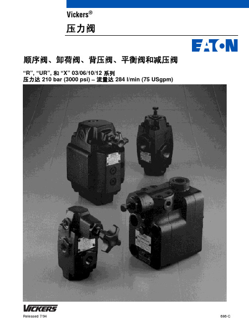
“R”, “UR”, 和“X” 03/06/10/12 系列压力达 210 bar (3000 psi) – 流量达284 l/min (75 USgpm)顺序阀、卸荷阀、背压阀、平衡阀和减压阀Vickers ®压力阀引言“R”系列顺序阀、卸荷阀、背压阀和平衡阀这种基本阀的几种配置能够通过改变 盖板位置来完成。
下面对每种功能进行简单介绍。
顺序阀和卸荷阀威格士 “压力平衡” 式压力控制阀通过内控或者外控方式引入一个压力飞升来用于控制液压系统中油流的卸荷和顺序。
可供货有以下形式:顺序阀,2 型-内控式;顺序阀,3 型-外控式;卸荷阀 4 型-外控式。
背压阀背压阀标记为 1 型-内控式,它们用于控‘ P ’ 品种也有货,用于制动回路。
平衡阀威格士“压力平衡”式平衡阀通过内控或者外控方式引入一个压力飞升来用于控制液压系统中的油流的卸荷和顺序。
可供货的有以下型式:平衡阀,1 型-内控式,平衡阀,4 型-外控式,这些阀通常用于保持系统中垂直负载不下降。
所有型号都有内置单向阀提供反向自由流动,(当不需要反向自由流动时,参考不带内置单向阀的平衡阀)。
“UR”系列卸荷溢流阀,带内置单向阀内置单向阀防止从蓄能器通过卸荷阀的回油。
在蓄能器系统中,当蓄能器压力达到调定的最高压力时,阀自动切断,在切入压力下(约为调定最高压力的 85%)阀自动使流量通向蓄能器和液压系统。
在双泵系统中,阀自动决定顺序,使泵的输出在低压下为大流量,在高压下为小流量。
“UR T”标记的型号有螺纹油口,并且要求单独的单向阀,起到卸荷回路的功能。
“X”系列减压阀这些减压阀保持出口压力在一个减压的等级上,不受进口压力在高于阀的设定压力以上变化的影响。
在压力低于阀的设定值下,阀也允许反向自由流动。
目录表R(C)*-03/06/10/12 系列顺序阀、卸荷阀、背压阀和平衡阀 ............................................................3 UR T*-06/10 系列卸荷阀溢流阀 ...................................................................................14 UR G*-06/10 系列卸荷阀溢流阀...................................................................................17 XS L/XTL-03 系列减压阀 ........................................................................................21 XG L-03 系列减压阀.............................................................................................23 X(C)*-03/06/10 系列减压阀 ......................................................................................26应用数据 ......................................................................................................35给液压执行器提供背压防止超速。
EATON Vickers 比例阀 说明书
特征和优点
● 这种全球性产品的制造按照世界级质量 ● 为提高可靠性பைடு நூலகம்性能,所有阀的 NFPA ● 阀和放大器作为一个性能经过测试的组
标准,并在全球范围内销售和服务。
疲劳额定值是 350 bar (5075 psi)。
件进行选择、订货、交货和安装。
● 由于采用威格士 DG4V-3 (S) 电磁换向 ● 全封闭的电磁线圈使普通工业用油无 ● 减少和简化了安装接线。
阀的通用部件,KDG4V 阀和 KTG4V 法渗透。线圈的拆卸和更换非常便捷容
* Viton 是 DuPont 公司的注册商标。
2
目录
概述
典型应用,进口节流和出口节流,阀芯位置,流量,推荐油液,压力补偿,
附件,电气信号,电气插头. . . . . . . . . . . . . . . . . . . . . . . . . . . . . . . . . . . . . . . . . . . . . . . . . . . . . . . . . . . . . . . . . . . . . . . . . . . 4 典型阀的剖视图,图形符号 . . . . . . . . . . . . . . . . . . . . . . . . . . . . . . . . . . . . . . . . . . . . . . . . . . . . . . . . . . . . . . . . . . . . . . . . . . . . . 5 用于阀选择的系统计算 . . . . . . . . . . . . . . . . . . . . . . . . . . . . . . . . . . . . . . . . . . . . . . . . . . . . . . . . . . . . . . . . . . . . . . . . . . . . . . 6 KDG4V-3S 和 KTG4V-3S 标准性能阀 – 100 bar (1450 psi) 油箱管路额定值 型号编法 . . . . . . . . . . . . . . . . . . . . . . . . . . . . . . . . . . . . . . . . . . . . . . . . . . . . . . . . . . . . . . . . . . . . . . . . . . . . . . . . . . . . . . . . . . . 7
VICKERS比例阀安装使用技术资料
VICKERS比例阀安装使用技术资料VICKERS比例阀安装使用技术资料VICKERS比例阀和伺服阀主要由电机械转换器和气动放大器组成。
但随着近年来廉价的电子集成电路和各种检测器件的大量出现,在1电气比例/伺服阀中越来越多地采用了电反馈方法,这也大大提高了比例/伺服阀的性能。
电气比例/伺服阀可采用的反馈控制方式,阀内就增加了位移或压力检测器件,有的还集成有控制放大器。
一、滑阀式美国威格士VICKERS方向比例阀流量式四通或五通比例控制阀可以控制气动执行元件在两个方向上的运动速度,这类阀也称方向比例阀。
图示即为这类阀的结构原理图。
它由直流比例电磁铁1、阀芯2、阀套3、阀体4、位移传感器5和控制放大器6等赞成。
位移传感器采用电感式原理,它的作用是将比例电磁铁的衔铁位移线性地转换为电压信号输出。
VICKERS电磁阀(又是安全阀)的主阀按配合形式不同可分为三级同心、二级同心和滑阀式三类.其中滑阀式结构工作压力低,控制压力精度不高;三级同心结构虽成熟,目前应用较广,但与二级同心式比较,不及二级同心式动作灵敏,规格相同,行程相同时,二级同心结构的通油能力远大于三级同心结构;二级同心式控制压力稳定,加工工艺性好,二级同心式应用前景广阔,这里以二级同心结构,讨论其结构尺寸设计方法.VICKERS电磁阀出来的先导油控制主换向阀阀芯的移动,使工作泵的来油进入动臂油缸实现动臂上升。
比例先导减压阀的输出压力越大,控制主换向阀阀芯的位移越大,主换向阀通过的流量越大,动臂上升的速度越快。
当操作手柄拉*限位置时,手柄中的限位电磁铁通电,手柄在极限位置被吸合。
动臂以zui大的速度上升,当升至动臂上位限位开关所限定的位置时,操作手柄限位电磁铁断电,手柄自动恢复到中位,动臂就可保持在所限定的位置。
在动臂上升的过程中,若需要动臂在某一位置停留,则需将操作手柄退回中位。
VICKERS电磁阀主要用在电气液压伺服系统中作为执行元件(见液压伺服系统)。
比例方向控制阀比例阀-Vickers伊顿威格士
比例阀
比例方向控制阀
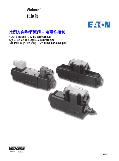
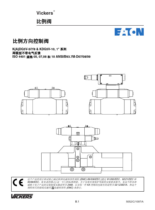
K(A)DG5V-5/7/8 & KDG5V-10, 1* 系列 两级型不带电气反馈 ISO 4401 规格 05, 07,08 和 10 ANSI/B93.7M-D07/08/09
这个产品的设计和试验已满足欧洲电磁相容性规程 (EMC) 89/336/EEC (通过 91/263/EEC,92/21/EEC 和 93/68/EEC,第 5 款的修正) 这一专门的标准纲要。关于实现有效保护等级的安装要求细节,见这个样本和 威格士电子产品的安装接线实施说明书 2468,以及每一件 KA 型阀均包装有的说明书 02-123931A。和这个 规程相关的接线实施用 电磁相容性 (EMC) 来指示。
关闭
7=
P 口打开至 A 和 B
12 =
当阀芯对中时全部油口关
闭,当阀芯通电时有差动
功能
33/133 = 当阀芯对中时,A,B 排
放至 T
4 阀芯/弹簧配置 C = 阀芯弹簧对中
5 额定流量
见 B.6 页的"阀芯数据" 额定流量 (L/min) 用于对称阀芯: "A" 口的额定流量 (L/min)用于非 对称阀芯
这类阀为每次工作循环中有重复负载条件 的应用场合,例如注塑机中的合模/开模, 提供有效而经济的解决方案。
带内装放大器的 5,7,8 规格的阀有货。
特征和优点
● 这种阀的制造是按照世界级的质量标 准,并且在全球范围内销售和维修。
● 这种阀作为反馈型比例阀和伺服阀的 一种成本有效的代替品,拓展了应用前 景。
减压阀模块 见 "型号编法"
主级 阀芯型式 “2C” 所示
7 针插头
- 1、下载文档前请自行甄别文档内容的完整性,平台不提供额外的编辑、内容补充、找答案等附加服务。
- 2、"仅部分预览"的文档,不可在线预览部分如存在完整性等问题,可反馈申请退款(可完整预览的文档不适用该条件!)。
- 3、如文档侵犯您的权益,请联系客服反馈,我们会尽快为您处理(人工客服工作时间:9:00-18:30)。
VICKERS比例阀技术使用操作细节资料
VICKERS比例阀技术使用操作细节资料
VICKERS比例阀实质上是一种廉价的、抗污染性能较好的电液
掌控阀。
美国VICKERS比例阀的进展经过两条途径,一是用比例电
磁铁取代传统液压阀的手动调整输入机构,在传统液压阀的基础下:进展起来的各种比例方向、压力和流量阀;二是一些原电液伺服阀
生产厂家在电液伺服阀的基础上,降低设计制造精度后进展起来的。
美国VICKERS比例阀是一种把输入的电信号按比例转换成力或
位移,从而对压力、流量等参数进行连续掌控的一种液压阀。
美国VICKERS比例阀是由直流比例电磁铁与液压阀两部分构成。
其液压
阀部分与一般液压阀差异不大,而直流比例电磁铁和一般电磁阀所
用的电磁铁不同,采纳比例电磁铁可得到与给定电流成比例的位移
输出和吸力输出。
随着液压传动和液压伺服系统的进展,生产实践中显现一些即
要求能够连续的掌控压力、流量和方向,又不需要其掌控精度很
高的液压系统。
由于一般的液压元件不能满足具有肯定的伺服性要求,而使用电液伺服阀又由于掌控精度要求不高而过于挥霍,因
此近几年产生了介于一般液压元件(开关掌控)和伺服阀(连续
掌控)之间的美国VICKERS比例阀。
VICKERS电磁阀对介质干净度有较高要求,含颗粒状的介质不
能适用,如属杂质须先滤去。
另外,粘稠状介质不能适用,而且,特定的产品适用的介质粘度范围相对较窄。
VICKERS电液掌控方向阀型号多样,用途广泛。
电磁阀虽有先天不足,优点仍非常突出,所以就设计成多种多样的产品,充足各种不同的需求,用途极为广泛。
电磁阀技术的进步也都是围围着如何克服先天不足,如何更好地发挥固有优势而打开。
1,电磁阀里有密闭的腔,在的不同位置开有通孔,每个孔都通向不同的油管,腔中心是阀。
电磁线圈被直接安装在阀体上,阀体被封闭在密封管中,构成一个简洁、紧凑的组合。
VICKERS CGE0632?
VICKERS CGE10300212
VICKERS CGE10320
VICKERS CGE10322
VICKERS CGE20321
VICKERS CMRSA11VICKERS CS06F5
VICKERS CS06F5?
VICKERS CT06C50
VICKERS CVC25C3AB29W10
VICKERS CVG25C1S2W243
VICKERS CVU16EFP1B2919
VICKERS CVU16EFP1B291931 VICKERS CVU16EFP1B291931EN19 VICKERS CVU16EFP1B291939 VICKERS CVU16SWD3B29H10 VICKERS CVU250CB2910
VICKERS CVU25EFP1B203010 VICKERS CVU25EFP1B294511 VICKERS CVU25EFP1B294531 VICKERS CVU25EFP1B294631 VICKERS比例阀技术使用操作细节资料。