HP服务器上安装与管理HP磁盘柜
HP小型机操作系统安装配置指导书(个人总结)

在HP Integrity Server开机后,可能屏幕没有任何显示,请使用串口线登陆系统的MP,进行管理。
下面将分为MP的管理、HP-UX的安装、HP的卷组操作和MC/Service Guard四章来说明。
HP Integrity Server MP在HP Integrity Server中有一块MP卡,该卡负责对系统的状态进行监视和控制。
该卡在系统插上电源后即被激活,无论操作系统是否启动,系统是否开机。
该卡提供了串行和网络两种接口可供访问。
1、连接串口连接方式:对于RX2600类型的机器,在后面板上有一个25针的接口,该接口在写着MP Management的一个框中,使用随机带的1对3接口(一边25针接口,另一边3个九针的接口),把串口线一边接到3个九针接口中写着“console”的接口上(串口线的线序为1-1,2-3,3-2,4-6,5-5,6-4,7-8,8-7,9-9),另一边接到笔记本上的串口上,然后可以使用Windows自带的超级终端程序对系统进行访问。
对于RX4600类型的机器,可能没有25针接口,而有三个九针的串口,其中之一为Local Console,则把串口线的一端接到Local Console口即可。
网络连接方式机器在出厂之日,处于安全的考虑,给MP上的网卡设置的IP为127.0.0.1,所以在使用串口连接去修改MP网络的配置之前,不能使用网络连接方式。
对于网络的配置,请参见本文后面的内容。
使用超级终端和串口连接系统在Window系统中启动超级终端程序,选择COM1口连接,其中配置为然后连接系统,则连接上以后可以输入“Enter”或者“Ctrl+B”,看是否有字符出现,如果有,则表示连接正确,否则请检查串口线及连接的情况。
一、常用命令在输入Ctrl+B后,系统应该提示登陆,如下图所示:在其中输入用户名Admin和口令Admin,注意大小写完全匹配,然后登陆登陆进入系统后便进入到MP的管理界面CO:在主菜单模式下输入co,可以使屏幕脱离MP管理状态进入到OS的Console界面,可以进入到操作系统之中,然后操作和在普通的终端上操作并无区别。
HP服务器进行RAID设置具体方法详解
1、使用惠普服务器集成的Smart P410i控制器hp服务器中有一个集成的磁盘阵列控制器,通过它可以配置服务器中的磁盘组成RAID,使系统中存储的数据更安全可靠。
我们可以如下操作使RAID(关于raid什么意思可参考/tech/tech_354.html一文):卡可用。
首先在服务器启动过程中,出现“Press to enter SETUP”提示时,按F2键进入SETUP,修改服务器的BIOS设置。
在服务器的BIOS设置界面中,选择“User Preferences”项,确认“Integrated HP NetRAID”所对应的内容为“Enabled”,并且把它的下一级选项“Included SCSI_A Channel”设为“Yes”,即把磁盘阵列控制器设为可用,并把服务器上的SCSI A通道包括在磁盘阵列控制器中。
按F10键保存设置并退出BIOS,重新启动服务器。
接着在服务器重新启动过程中,出现“Option:Experienced users may press for HP NetRAID Express Tools Now.”时,按Ctrl+M组合键进入HP NetRAID快速配置工具。
在“Tools Management Menu”菜单下,选择“Configure → Clear Configuration”,清除原先的配置,如以前没有配置RAID,则会出现“No Existing Configuration to Clea r” 的提示;如系统配置了RAID,则提示“Clear Configuration?”,选择“Yes”清除配置。
按“Esc”键返回配置菜单,选择“New Configuration”,对“Proceed?” 回答“Yes”,服务器会开始查找磁盘,查找结束后,所有找到的磁盘会在“New Configuration-ARRAY SELECTION MENU”菜单下显示为“READY”就绪状态此时依次按空格键选中要添加到阵列中的磁盘,显示为“ONLIN”在线状态,选中所有的磁盘后,按回车键结束阵列的选择;再按回车键进入“Logical Drives Configured”菜单,选择RAID的级别,阵列容量的大小,以及修改“Advanced Menu”高级菜单中的条带容量(Stripe Size),写入策略(Write Policy),读取策略(Read Policy)和高速缓存策略(Cache Policy)选项,它们的默认值为“Stripe Size=64KB”,“Write Policy=WRTHRU”,“Read Policy=ADAPTIVE”和“Cache Policy=CachedIO”,用户可以根据所使用服务器的具体情况进行设置。
HP服务器安装培训-磁盘柜安装

flexible and scalable high connectivity entryentry-level fibre high scalability channel storage
scalable modularity heterogeneous ease of administration price/scalability
SCSI 磁盘柜的安装 MSA20 磁盘柜的安装:
硬件安装
Rear Components Item Description
1 Arrow buttons (for future use) 2 Enclosure ID display—Indicates the box ID number assigned to the enclosure during drive configuration 3 Unit identification button—Causes the blue LED on all drives in the enclosure to be illuminated 4 Enclosure Monitor status LED—Glows green to indicate that the enclosure monitor (Global Service Indicator, or GSI) is functional. 5 Enclosure fault LED—Glows amber when any other LED in the enclosure is amber, if the GSI is functional 6 Enclosure power button 7 Power supply units 8 Fan assemblies 9 Controller module
HP服务器安装
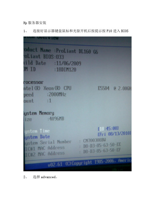
Hp服务器安装
1、连接好显示器键盘鼠标和光驱开机后按提示按F10进入BIOS
2、选择advanced。
3、在advanced下选择SATA Configuration 回车
4、选择RAID。
4、按F10保存退出重启。
5、在出现如下图选项时选择F7将两块硬盘组RAID1(1+0)。
drive
盘。
8、让服务器重光盘启动。
9、看到如下选项看直接点击右下角NEXT。
10、按AGREE同意条款。
11、选择Install。
12、查看要安装的硬盘,直接点击右下角NEXT。
13、按如下图选择所要安装的服务器系统。
然后点NEXT。
14、在如下图中选择默认,然后直接点NEXT。
盘系统盘大小为20480M,然后点击右下角NEXT。
16、在organization name 中填入weiwei,在owner name中填入weiwei,在product key中填入系统的key。
其他选项为默认,然后
点击右下角NEXT。
17、下面的选项为默认,直接点击右下角NEXT。
18、下图是提示数据会丢失,直接点右下角NEXT。
19、开始格式化光盘和考入驱动。
20、提示放入系统光盘复制安装文件。
21、复制完成后自动重启取出系统光盘,让系统重硬盘安装。
然后点下一步。
23、安装完成后直接重启后完成。
进入系统后设置硬盘的扩展分区和逻辑分区。
最终硬盘分为三个盘C(sys)20G、D(data)30G、E(bak)
200G。
HP服务器与存储系统安装、管理与故障排查指南说明书

This document is for the person who installs, administers, andtroubleshoots servers and storage systems. HP assumes that you are qualified in servicing computer equipment and trained in recognizing hazards in products with hazardous energy levels.© Copyright 2005 Hewlett-Packard Development Company, L.P .Hewlett-Packard Company makes no warranty of any kind with regard tothis material, including, but not limited to, the implied warranties of merchantability and fitness for a particular purpose. Hewlett-Packard shall not be liable for errors contained herein or for incidental or consequential damages in connection with the furnishing, performance, or use of this material.This document contains proprietary information, which is protected by copyright. No part of this document may be photocopied, reproduced, or translated into another language without the prior written consent of Hewlett-Packard. The information contained in this document is subject to change without notice.Hewlett-Packard Company shall not be liable for technical or editorial errors or omissions contained herein. The information is provided “as is” without warranty of any kind and is subject to change without notice. The warranties for Hewlett-Packard Company products are set forth in the express limited warranty statements accompa-nying such products. Nothing herein should be construed as constituting an additional warranty.Printed in the U.S.A.hp ProLiantDL585 Storage ServerHP ProLiant DL585 Storage Server Installation Instructions First Edition (March 2005)Part Number: 389150-001WARNING: This product contains energy levels that areconsidered hazardous. To reduce the risk of personal injury from electric shock and hazardous energy, individuals who are knowledgeable of the procedures, precautions, and hazards associated with equipment containing hazardous energy circuits must perform the installation and servicing of this product.•Obtain adequate assistance to lift and stabilize the chassis during installation or removal.•Be aware that the product becomes unstable when it is not fastened to the rails.•Before removing the server from the rack, remove all hot-plug power supplies, power modules, and drives to reduce the overall weight of the product.•Extend leveling jacks fully to the floor and make sure that the full weight of the rack rests on the leveling jacks.•Install stabilizing feet on single-rack installations.•Couple multiple-racks.•Only extend one rack component at a time. The rack will become unstable if more than one device is extended.A rack resource kit ships with all HP branded or Compaq branded 9000,10000, and H9 series racks. For more information on the content of each resource, refer to the rack resource kit documentation.If you intend to deploy and configure multiple servers in a single rack,refer to the white paper on high-density deployment at the HP website./products/servers/platformsThe HP ProLiant DL585 Storage Server is preloaded with the Windows ®Storage Server 2003 operating system. Prior to power up, deployment instructions found in the “User Guide” should be followed to enable the successful configuration of the storage server in addition to the guidelines found below.Required Items:User GuideAdministration GuideTo begin the first-time startup procedure:Be sure that the server is safely installed in an adequateenvironment.Be sure that the power cables and peripheral devices are plugged inand AC power is supplied to the server.Refer to the User Guide prior to powering up the server.389150-001Remove shipping bracket from the PCI Basket, loosen thethumbscrew (1) and remove and discard the shipping bracket (2).NOTE: The shipping bracket is used only to secure the PCIlatches during shipment.Install optionsIf you are installing additional options, such as expansion boards,processors, hard drives, or memory, refer to the instructionsincluded with the option.NOTE: For quick start memory guidelines, refer to the hood labels on theserver.1.Install the rails on both sides of the chassis.2.Pull the rail compression lever toward you.3.Install the rear of the rail into the designated holes in the rear ofthe rack.4.Install the front of the rail into the designated holes in the frontof the rack.5.Install the rails on the chassis into the rails in the rack.6.Slide the server onto the rack rails until the lockingpin engages.7.Tighten the thumbscrews to secure the server to the rack.The ProLiant DL585 server can operate either on a 120-V or a 240-V AC input. Two AC inlets are on the rear of the server, one for each power supply installed.WARNING: To reduce the risk of electric shock or damage to the equipment:•Do not disable the power cord-groundingplug. The grounding plug is an important safety feature.•Plug the power cord into a grounded (earthed)electrical outlet that is easily accessible at all times.•Disconnect power from the server by unpluggingthe power cord from either the electrical outlet or the server.To connect the power cord:1.Locate the correct voltage line cord that came with the server. Remove any labels that cover the cord connector.IMPORTANT: To connect the power cord, plug it into the appropriate power supply AC inlet. The power connector is connector number one for the primary (populated) power supply and is connector number two for the redundant hot-plug power supply.2.Plug the other end of the power cord into a grounded electrical outlet or UPS, depending on power cord type.3.Connect the peripheral device cables to the server, and then route the power cord and device cables through the cable management arm.Attaching cable management arm to a square-hole rack1.Slide the bracket onto the rack (1).2.Insert the bracket hooks into the square holes on the rack, and then push down to secure (2).3.Tighten the thumbscrew to stabilize the cable management armon the rack (3).Attaching the cable management arm to a round-hole rack1.Remove the square-hole bracket from the cable management arm by pulling out the spring-activated fasteners (1), and thenpulling out the bracket (2).2.Attach the round-hole bracket by pulling the spring-activated fasteners on the cable management arm out (1), and then inserting the bracket between them (2).3.Slide the bracket onto the rack (1).4.Attach the cable management arm to the round-hole rack, andthen secure the thumbscrews (2).To register your product visit the HP Registration web site at:Attaching the cable management arm to the server1.Loosen the thumbscrews on the front of the server to enable theserver to slide forward.3.Secure the cables to the inside of the cable management arm using the V elcro straps.2.Align the keyholes on the cable management arm with the postson the server (1), and then secure with the thumbscrew (2).Securing the cables to the cable management arm1.Align the pivot points of the cable management arm by slidingthe server as needed.2.Pivot the arm away from the server.4.Close the cable management arm and finish securing the cables.The hardware installation is now complete. Please refer to the “HP ProLiant Storage Server User Guide.”Installation Instructions Rack template tool used during rack installation contains:Administration guide User GuideHP Warranty fulfillment documentprovides instructions to obtain a printed warrantyHP Important Safety Information bookletSafety information for HP storage, power,networking and rack productsDocumentation CDrequirements and configuration options User Guiderack installation poster Administration Guideprovides administrative and procedural instructions to manage the storage server。
HPDL360G7服务器安装说明

Create Array创建阵列
勾选Select All,选中系统检测出的磁盘,后点右下角<OK>
Create Logical Drive创建逻辑驱动器
单击右侧页面<Create Logical Drive>创建逻辑驱动器,或鼠 标右键点左侧树结构的驱动器创建。
Create Array创建阵列
操作系统安装配置(共六步)
第三步:选择Custom,设置操作系统安装的磁盘分区大小, 单位是M,其他项默认,单击右下角<Next>下一步
操作系统安装配置(共六步)
第四步:填写安装信息从上到下依次是计算机名称、管理员密码、 管理员密码确认量,填写完成后单击右下角<Next>下一步。
HP服务器安装说明
安装前准备
HP服务器随机器带的引导盘
操作系统安装光盘
引导盘说明
引导盘分为64位和32位两张,举例为64位操作系 统安装。(HP SmartStart)
服务器启动
按服务器电源开关,服务器启动,将HP SmartStart光盘放入 光驱。服务启动页面如下:
服务器启动
服务器会自动选择有光驱引导启动
第五步:此显示的是之前配置的安装信息,在确认无误后, 单击右下角<Next>进行安装,如有错误单击<Previous>返回 重新配置。
操作系统安装配置(共六步)
第六步:安装进度在27%后弹出HP SmartStart光盘,更换操 作系统安装光盘。
操作系统安装配置
第六步:安装进度在100%后弹出操作系统光盘,服务器自 动重启,进入蓝屏安装页面,复制文件。
Windows操作系统安装
单击<完成>,至此完成了操作系统的安装,进入系统,打 开设备管理器,查看设备状态。
HP MSA1000安装手册
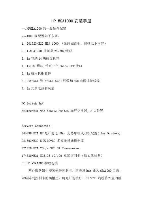
HP MSA1000安装手册一.HPMSA1000的一般硬件配置msa1000因配置如下东西:1.201723-B22 MSA 1000 (光纤磁盘柜,包括以下内容)2.1xMSA1000 控制器/256MB 缓存3.1x容纳14块硬盘机箱4.1xI/O 模块,带有一个2Gb/s SFP接口5.1x通用机柜套件6.2xVHDCI 到 VHDCI SCSI线缆和PDU电源连接线缆7.2x冗余电源和风扇FC Switch SAN322120-B21 MSA Fabric Switch 光纤交换器, 8口外置Servers Connectio:245299-B21 HP光纤通道HBA,支持单机或双机配置( for Windows) 221692-B22 5米LC-LC 多模光纤通道电缆221470-B21 2Gb/s SFP SW Transceive174830-B21 NC3123 10/100 单通道网卡(做心跳侦测)二.HP MSA1000物理连接两台服务器中安装光纤控制卡,将光纤hub插入MSA1000后面,对应阵列控制卡的插槽里,将光纤连接好。
用SCSI线缆将外置的磁盘阵列柜与MSA1000连接.备注: 服务器分别与阵列柜连接(使用2G光纤跳线),特别注意,SAN阵列柜自带一个FC口的模组,另选配了一个2/3 FC HUB 模组 (就是自带带2个FC口,无其它特别之处。
)实际我们只是用2/3 FC HUB 模组连接2台服务器,由于我们SAN 前面板我们只安装了一个控制模块,后面只有一个模组可用(咨询HP工程师得到的答案)所以,请把安装在后面的2/3 FC HUB模组的位置,对着前面控制模组的位置从后面安装进去,这样就可以了,另外一个不可用的模组上的2个灯为黄色闪烁,三.服务器和相关软件的安装(以win2000操作系统为例)(安装系统) 首先在BIOS中选择OS为 windows2000/windows2003,然后用HP服务器自带的 BOOT CD引导服务器,出现图形界面的向导,点击 Setup图标,选择OS类型,选择OS分区大小,选择安装win2kadserver,输入CD-KEY,放入安装光盘,剩下的安装过程就都是自动的了。
HP MSA1000磁盘柜安装步骤
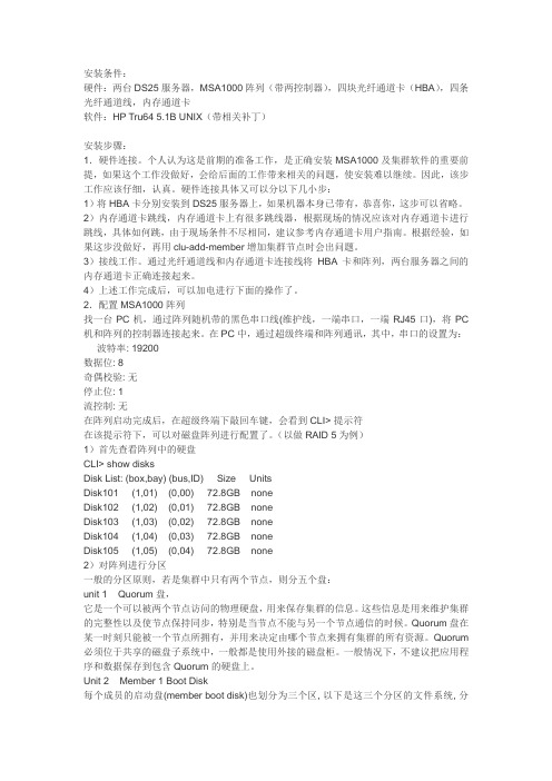
安装条件:硬件:两台DS25服务器,MSA1000阵列(带两控制器),四块光纤通道卡(HBA),四条光纤通道线,内存通道卡软件:HP Tru64 5.1B UNIX(带相关补丁)安装步骤:1.硬件连接。
个人认为这是前期的准备工作,是正确安装MSA1000及集群软件的重要前提,如果这个工作没做好,会给后面的工作带来相关的问题,使安装难以继续。
因此,该步工作应该仔细,认真。
硬件连接具体又可以分以下几小步:1)将HBA卡分别安装到DS25服务器上,如果机器本身已带有,恭喜你,这步可以省略。
2)内存通道卡跳线,内存通道卡上有很多跳线器,根据现场的情况应该对内存通道卡进行跳线,具体如何跳,由于现场条件不尽相同,建议参考内存通道卡用户指南。
根据经验,如果这步没做好,再用clu-add-member增加集群节点时会出问题。
3)接线工作。
通过光纤通道线和内存通道卡连接线将HBA卡和阵列,两台服务器之间的内存通道卡正确连接起来。
4)上述工作完成后,可以加电进行下面的操作了。
2.配置MSA1000阵列找一台PC机,通过阵列随机带的黑色串口线(维护线,一端串口,一端RJ45口),将PC 机和阵列的控制器连接起来。
在PC中,通过超级终端和阵列通讯,其中,串口的设置为:波特率: 19200数据位: 8奇偶校验: 无停止位: 1流控制: 无在阵列启动完成后,在超级终端下敲回车键,会看到CLI> 提示符在该提示符下,可以对磁盘阵列进行配置了。
(以做RAID 5为例)1)首先查看阵列中的硬盘CLI> show disksDisk List: (box,bay) (bus,ID) Size UnitsDisk101 (1,01) (0,00) 72.8GB noneDisk102 (1,02) (0,01) 72.8GB noneDisk103 (1,03) (0,02) 72.8GB noneDisk104 (1,04) (0,03) 72.8GB noneDisk105 (1,05) (0,04) 72.8GB none2)对阵列进行分区一般的分区原则,若是集群中只有两个节点,则分五个盘:unit 1 Quorum盘,它是一个可以被两个节点访问的物理硬盘,用来保存集群的信息。
- 1、下载文档前请自行甄别文档内容的完整性,平台不提供额外的编辑、内容补充、找答案等附加服务。
- 2、"仅部分预览"的文档,不可在线预览部分如存在完整性等问题,可反馈申请退款(可完整预览的文档不适用该条件!)。
- 3、如文档侵犯您的权益,请联系客服反馈,我们会尽快为您处理(人工客服工作时间:9:00-18:30)。
HP服务器上安装和管理HP 磁盘柜MSA500G2(Redhat Linux AS3.0字符环境)目录:●一、磁盘柜硬件安装;page 1●二、驱动和工具软件安装;page 1●三、阵列配置;page 2●四、系统监控 page12先给服务器安装操作系统Redhat Linux AS3.0。
一、磁盘柜硬件安装默认的SCSI口认不到MSA500G2控制器,因此服务器必须插一块Smart Array642卡(每台MSA500G2都带2块Smart Array642卡),由于SA642是全长的PCI-X卡,因此服务器必须能提供全长的PCI-X插槽。
连接线缆,先开磁盘柜,等2分钟后再开服务器。
二、驱动和工具软件安装1、以超级用户root登录Linux系统,将随盘柜或自己下载的HP SmartStart光盘放入服务器光驱中。
(最新SmartStart下载地址:r/us/subscription/PSM_subscription.html)#mount –t iso9660 /dev/cdrom /mnt#cd /mnt/compaq/csp/linux#ls *.sh –l2、执行看到的.sh文件,例如#./install760.sh在这个过程中会回答一些系统管理问题,一部份是有关SNMP有关的,一部份是与管理帐号和安全的,可以过后再配(本文第四节),可以使用默认设置,必须输入的先随便输入。
这个过程会安装HP驱动(包括网卡驱动)、管理和配置软件。
3、检查安装效果#lsmod |grep cciss应该显示 ciss 。
如没有:#insmod cciss用vi编辑 /etc/rc.local,加入:insmod ccisscpqacuxe –R4、重启服务器#cd /#umount /mnt#reboot三、阵列配置有三种方式配置阵列:●方法1:用HP SmartStart CD启动服务器,启用ACU(Array Configuration Utility)配置阵列;(图形界面,最方便使用);●方法2:用Linux下命令行配置(可以做ACU所有工作,又增加改MSA500G2名称等功能);●方法3:在网络环境下,在一台PC上用浏览器登录服务器管理界面(System ManagementHomepage),在里面启用ACU-XE,界面和方法1一样。
MSA500G2共有14颗146GB磁盘,建议仅定义一个磁盘组(Array),包含13颗磁盘,此磁盘组划分成4个逻辑盘,分别标记为logical disk1-4,下图,每个逻辑盘都用到13个硬盘的一部分(在操作系统看来是4个物理盘)每个逻辑盘采用RAID5模式,第14颗硬盘作为热备援盘。
当阵列中某个物理磁盘损坏时,自动加入到阵列中,参与阵列,此时系统从其它磁盘读数据,运算后写入此磁盘,此过程称为重构(rebuild)。
从以下(一)、(二)、(三)中挑一个方法来配置成上述效果。
(一)方法11、用HP SmartStart CD启动服务器;启用ACU(Array Configuration Utility)工具(要用到鼠标):2、ACU会自动扫描所有的阵列卡(机器内部集成的,Smart Array 642)和MSA500G2;点中MSA500G2;3、观察检测到的硬盘,看有没有事先的设置,如果有且数据不用,删除掉。
4、先创建磁盘组(Create Array):5、再分别创建4个逻辑盘(Create Logical Drive):根据需要配置每个逻辑盘的参数:RAID级别,条带大小(stripe size),逻辑盘大小(Logical Drive Size,最后一个用默认)。
ss 是条带大小(stripe size),单位是KB;(性能调优:a.混合读写:使用默认;b.主要连续读,例如语音和视频应用:stripe size调大;c.主要是写:例如图象处理:RAID5或6用小的stripe size,RAID0和1+0用大的stripe size);. raid 级别必须是本控制器能支持的,缺省是RAID6(ADG,可损坏任意两颗硬盘,但性能比RAID5略低8%~15%)5、设置备援盘注:以上配置(RAID5+热备援)与选择14颗硬盘做RAID6(ADG)相比,磁盘利用率都是(14-2)/14; RAID6可靠性更高,但是性能比RAID5低10%左右。
保存,退出ACU。
(二)方法2:用命令行的阵列配置1、以超级用户root登录Linux系统,输入阵列配置命令行#cpqacuxe -stop#hpacucli全称缩写解释全称缩写解释adapterid ai 适配器ID号serialnumber sn 控制器序列号arrayaccelerator aa 缓存cacheratio cr 读写缓存比率logicaldrive ld 逻辑盘,即能被操作系统看见的卷physicaldrive pd 真实的物理硬盘,操作系统不可见chassisname ch 盘柜名字,可自己修改controller ctrl 控制器2、扫描和察看阵列卡=> rescan=> ctrl all show此时应该可以看到SA642和MSA500G2两个控制器,可能是这样显示:MSA500G2 in 22K9LYPN44 (sn=xxxxxxxxxxxxxxxxxx xxxxxxxxxxxxx)Smart Array642 in slot 0 (sn=xxxxxxxxxxxxxxxx )3、将冗长的盘柜名字从22K9LYPN44改成好用好记的=> ctrl ch=22K9LYPN44 modify ch=21cn4、设置目标控制器,这样后面命令都是指针对它,可以减少命令行长度=>set target ctrl ch=21cn5、查看控制器和其所有物理磁盘和逻辑盘=>show=>pd all show=>ld all show6、选择物理盘,组成磁盘组(Array),创建逻辑盘(卷);一个磁盘组可以划成多个逻辑盘,RAID级别是在逻辑盘指定的,即允许同一磁盘组的不同逻辑盘各采用不同RAID级别。
例如本测试里将14颗磁盘做进一个磁盘组,再将它划成5个大小接近的逻辑盘:=>create type=ld drives=1:1-1:13 size=420000 ss=32 raid=5=>create type=ld drives=1:1-1:13 size=420000 ss=32 raid=5=>create type=ld drives=1:1-1:13 size=420000 ss=32 raid=5=>create type=ld drives=1:1-1:13 ss=32 raid=5以上命令行中:. drives也可以随意选择非连续盘,用逗号(,)分开;. size 后数字的单位是MB;省略的话是采用所有可用空间做逻辑盘(见以上第4行);ss 是条带大小(stripe size),单位是KB;(性能调优:a.混合读写:使用默认;b.主要连续读,例如语音和视频应用:stripe size调大;c.主要是写:例如图象处理:RAID5或6用小的stripe size,RAID0和1+0用大的stripe size);. raid 级别必须是本控制器能支持的,缺省是RAID6(ADG,可损坏任意两颗硬盘,但性能比RAID5略低8%~15%)7、配置备援盘=>add spares=1:148、查看效果=>ld all show=>ld 1 show=>ld 2 show=>ld 3 show=>ld 4 show9、为逻辑盘启用阵列控制器缓存(如果新控制器或新缓存在,加电后,电池充电期间,缓存会被控制器禁用,一段时间后缓存才可用)=> ld all modify aa=enable10、修改阵列控制器缓存的读写比率,默认设为50% 比50%,可以根据应用环境自行调整。
=> modify cr=50/50*11、为物理盘启用缓存(MSA500G2不支持)=> modify dwc=enable其它设置和命令参阅文档《HP Array Configuration Utility User Guide》的“Using the Command Line Interface”一节。
12、退出=>quit#cpqacuxe –R(三)方法3第四章第(二)节配好后,从网上其它计算机访问本服务器的管理网页,:http://机器名或IP:2301或http s://机器名或IP:2381选择HP Array Configuration Utility;具体配置方法同第(一)节。
(四)验证设备名#fdisk /dev/cciss/c0d0[root@localhost init.d]# fdisk /dev/cciss/c0d0The number of cylinders for this disk is set to 105412.There is nothing wrong with that, but this is larger than 1024,and could in certain setups cause problems with:1) software that runs at boot time (e.g., old versions of LILO)2) booting and partitioning software from other OSs(e.g., DOS FDISK, OS/2 FDISK)Command (m for help): pDisk /dev/cciss/c0d0: 440.4 GB, 440402968064 bytes255 heads, 32 sectors/track, 105412 cylindersUnits = cylinders of 8160 * 512 = 4177920 bytesDevice Boot Start End Blocks Id SystemCommand (m for help): q#fdisk /dev/cciss/c0d1#fdisk /dev/cciss/c0d2#fdisk /dev/cciss/c0d3如果有2个msa500G2,另外的设备名就是/dev/cciss/c1d0/dev/cciss/c1d1/dev/cciss/c1d2/dev/cciss/c1d3HP DL380G5 内置E200阵列卡配的内置硬盘的设备名是:/dev/cciss/c2d0(如果分了多个逻辑盘就依次增加)/dev/cciss/c2d1....设备根据具体应用要求使用;一般先建分区(fdisk里用n);然后再直接使用裸设备(例如/dev/cciss/c0d0p0);也可做成文件系统(#mkfs 设备名)四、系统监控(一)Linux下基于命令行的察看#cpqacuxe -stop#hpacucli=> ctrl ch=21cn show=> ctrl ch=21cn ld all show=> ctrl ch=21cn ld 1 show=> ctrl ch=21cn pd all show=> ctrl ch=21cn pd 1 show如果一颗硬盘坏,上述含pd命令可看到。