Fault-Tolerant Storage and Quorum Systems for Dynamic Environments M.Sc. Thesis
Method and system for fault-tolerant transfer of f

专利名称:Method and system for fault-toleranttransfer of files across a network发明人:Michael Frederick Kenrich,Hal S.Hildebrand,Senthilvasan Supramaniam申请号:US10642041申请日:20030815公开号:US07555558B1公开日:20090630专利内容由知识产权出版社提供专利附图:摘要:Improved techniques for transferring files through a multi-tier computing environment are disclosed. The transfer of files across the multiple tiers of thecomputing environment can use staging at intermediate tiers to facilitate the file transfer. Each tier can include at least one computing machine that includes a file transfer manager. The file transfer managers at the computing machines in each of the multiple tiers serve to effectuate the file transfer through the multi-tier computing environment. In one embodiment, the multi-tier computing environment is a multi-tier file security system and the files being transferred are audit files.申请人:Michael Frederick Kenrich,Hal S. Hildebrand,Senthilvasan Supramaniam地址:335 Beach Dr. Aptos CA 95003 US,655 Sierra St. Moss Beach CA 94038 US,1487 Ormsby Dr. Sunnyvale CA 94087 US国籍:US,US,US代理机构:Sterne, Kessler, Goldstein & Fox PLLC更多信息请下载全文后查看。
国家石油和天然气有限公司(National Oilwell Varco)产品说明书

• Centralized datacenter environment hosts data, monitoring, analysis, support and report applications • Virtualization technology allows expandable software and extendable hardware independently • High availability, redundancy and disaster recovery of critical operations • Data provider for efficient capture, storage and retrieval of information • Software lifecycle management• Extensive system monitoring and administration •System hardening for emerging cybersecurity threatsRISE armrest design includes new screens, configurable buttons, encoder wheels, and an improved joystick that all together optimize the human-machine interaction during the different drilling processes. Additionally, the armrests include retractable cup holders.Our new joystick design includes tactile feedback to enhance the operator’s situational awareness and ultimately improve efficiency and safety.Our RISE workstation supports storing and restoring users’ ergonomic profiles, allowing the workstation to self-adjust to specific operator’s body measurements.The RISE workstation is the premium plaform for CYBERBASE systems.An operator’s physical well-being during drillingoperations significantly impacts rig crew performance. Hazards of sitting for extended periods of time includeincreased discomfort and increased risk of back injuries. In order to improve the driller’s well-beingduring operation, RISE provides a posture change ranging from any position betweensitting and standing.CYBERBASE ™ v14: The flexible, upgradable and reliable drilling control systemRISE ™: elevating the industry standardCYBERBASE™ is the original integrated drilling control system built for seamless integration of machine control, process management and information sharing. True to the original design, the CYBERBASE system works with any machine and complimentary system while maintaining optimal process safety and cybersecurity.CYBERBASE v14 bridges the challenge of aging technology through applying purposeful innovation:Drilling system data centerThe first in the industry data center solution to fully decouple software from hardware creating a truly future oriented system. A data center is inherently fault-tolerant by dynamic load sharing and allowing hot-swapping of hardware without interfering with the drilling operations. As a bi-product, the data center allows more computing and data storage capacity hence giving the end user faster response time, better information and cheaper upgrades. Solutions such as the drilling data, analysis and report functions, system health monitoring, eHawk™ remote support, digital CCTV solutions, Webdriller, NOV Alarm Statistics, Sdi.Connect etc. are co-hosted in data center as virtual machines.***********The CYBERBASE front-end stations use high reliability fanless smart clients. Networks are upgraded to improve capacity, reliability, scalability and maintainability.Capturing, storing and providing dataThe CYBERBASE system has many stakeholders consuming information such as drilling and machine data, manuals, configuration files and software management history.CYBERBASE solves the challenges associated with explosive growth in data and increasingly complex storage environments.CYBERBASE GUIsSoftware lifecycle managementTool controllers 1, 2 and 3Tool controllers 4, 5 and 6Drilling Control NetworkDrilling Control Network Prepared for 3rd PartyInterface BOPCement System Vessel ManagementOther SystemsDrilling Control InterfaceRISE Operator Station (A)RISE Operator Station (n)CCTVstreaming & soundService TerminalOffice WorkstationsRouterData CenterPrepared for Virtual MachineseHawkHuman Machine Interface CYBERBASE Data Provider Drilling Flight Recorder Alarm Statistics WebdrillerCYBERBASE System Monitoring RIG Sentry (Condition Monitoring)Torque Turn Drilllink Sdi ConnectKick Monitoring System Daily Drilling ReportPrepared for eHawk and onshore supportPrepared for Drilling Flight Recorder remote workstationCybersecurity hardeningCybersecurity is important and remains a high-focus for CYBERBASE by implementing defense-in-depth strategy.• Strict remote-access control through a DMZ and antivirus software protection• Managed USB ports, segregated network and firewalls help maintaining the air-gap • Application whitelisting prevents unintended applications from running•Extended system surveillance including deep packet inspection and network intrusion detectionNOV introduces RISE, the only driller’s workstation designed from the ground up to address ergonomic concerns, minimize fatigue, and keep your crew in top form with its industry-leading customizable operating positions. The development of RISE grew from years of ergonomic research and theory to offer your cabin crews the opportunity to work with better posture, less stress, and more focus on the job at hand. Our RISE workstation brings unprecedented chair adjustment options to custom-fit the operator’s body and provide optimal comfort.Key Features:• Sitting and standing operation• Unprecedented adjustments for optimal ergonomics • User storable multi-angle configurable positions •New 2-button joystick with operator feedbackRISE supports the following operator adjustments to maximize operator’s comfort:• Backrest incline/recline • Lumbar support • Knee support • Grip length • Elbow support• Armrest pillow slide • HMI slide & tilt • Swivel。
Fault-Tolerant Systems 11.1. What is a Fault

11Fault-Tolerant Systems11.1. What is a Fault ?Any action that does not conform to the given specification of a system is viewed as a fault. Historically, models of failures have been linked with the users level of interaction with a system. A VLSI designer may focus on stuck-at-0 and stuck-at-1 faults only, where the output of a gate is permanently stuck to either a 0 or a 1 regardless of input variations. A system level hardware designer, on the other hand, may be ready to view a failure as any arbitrary or erroneous behavior of a module as a whole. A drop in the power supply voltage, or radio interferences due to a lightning, or a cosmic shower, often causes transient failures that may temporarily perturb the system state without causing any permanent damage to the system. Finally, even if hardware does not fail, software may fail due to improper or unexpected changes in the specifications of the system. Before any discussion about how to tolerate such faults, it is important to present a proper characterization of the various kinds of faults that can occur in a system.11.2. Classification of FaultsOur view of a distributed system is essentially a process-level view, so we begin with the description of some important types of failures that are visible at the process level. Note that each type of failure at any level may be caused by a failure at some lower level of abstraction. Thus, a process may cease to produce an output when a wire in the circuit breaks. A complete characterization of the relationship between faults at different levels is beyond the scope of our discussion. Our classification of failures is as follows:Halting Failure. When a process that is expected to produce one or more messages, or change the values of some process variables, ceases to do so on a permanent basis, a halting failure occurs. Note that this is an irreversible change. Halting failures are also known as crash failures.In a variation of this model, halting failures are treated as reversible, i.e. a process may play dead for a finite period of time, and then resume operation. This includes thecase in which the faulty process is repaired and restarted after some time. Such failures are called napping failuresByzantine Failure. Byzantine failures correspond to completely arbitrary failure patterns, and is the weakest of all the failure models. As an example, let N.i denote the set of neighbors of a process i. Assume that i is expected to send a value x to every process in N.i. If process i does not send the intended value x to each of its neighbors, then the failure is called a byzantine failure. The following are some examples of inconsistent behaviors possibly caused by byzantine failure:¥ Two distinct neighbors j and k receive values x and y, where x ≠ y.¥ Every neighbor receives a value z where z ≠ x.¥ One or more neighbors do not receive any value from process i.Some of the possible causes of byzantine failures are¥ The total or partial breakdown of a link joining i with one of its neighbors ¥ Software problems in process i¥ Hardware synchronization problems - assume that every neighbor is connected to the same bus, and trying to read the same copy sent out by i, but since the clocksare not synchronized, they may not read the value x exactly at the same time. If x is a time-sensitive variable, then different neighbors of i may receive differentvalues from process i.¥ Malicious action by process i.Transient Failure. Certain types of fault actions have temporary effects on the global state of a system. Such failures perturb the global state in an arbitrary way, but the effect of the agent inducing this failure is not perceived thereafter. This is called a transient failure.A special kind of transient failure applicable to message-passing models only is the omission failure. Consider a transmitter process sending a sequence of messages to a receiver process. If the receiver does not receive some of the messages sent by the transmitter, then it is an omission failure. In real life, this can be caused either by transmitter malfunction, or by the loss of messages in transit.Software Failure. Software does not fade or erode with time. Assume that a system running under the control of a program S is producing intended results. If the system suddenly fails to do so even if there is no hardware failure, there is a problem withspecifications. If {P}S{Q} is a triple in programming logic, and the precondition P is inadvertently weakened, then there is no guarantee that the postcondition Q will always hold!The situation can be explained using the example of a pop machine. This pop machine delivers a can of pop, when a user inserts 50cents into the machine. The machine is designed to accept quarters and dimes only. If an uninformed user tries to buy a can of pop with ten nickels, then the machine will fail to deliver the pop, since the machine is not designed to accept nickels! This malfunction may be viewed as a software failure.Temporal Failure. Real time systems require actions to be completed within a specific amount of time. When this deadline is not met, a temporal failure occurs.11.3. Specification of FaultsWe present here a general model for specifying an arbitrary type of failure. This model was proposed by Arora and Gouda in [AG93]. A system description consists of (i) a set of specified actions S representing the fault-free system, and (ii) a set of fault actions F. The actions of F can be expressed using notations similar to those used in S.The faulty system consists of the union of all the actions in both S and F, and will be denoted by S F. An example of such a specification follows.Assume that a system, in absence of any fault, sends out the message "a" infinitely often (i.e. the output is an infinite sequence aaaaa...). However, a failure "occasionally" causes a message to change from "a" to "b". This description can be translated to the following specification1 :define x : booleana , b: messageinitially x = true;S::do x → send a odF::do true → send b odWith a weakly fair scheduler, the difference between the behaviors of S and S F becomes perceptible to the outside world.1 This specification is not unique. Many other specifications are possible.A halting failure of S can be represented using the following specification for F:F :: do true →x := false odAfter this fault action is executed, the system ceases to produce an output -- a condition that cannot be reversed using the actions in S or F.Now, consider a system that receives a message msg, and forwards it to each of its N neighbors {0, 1, 2, ..., N-1}. This can be specified byS::initially j = 0, flag = falsedo¬flag ∧ msg = a→x := a; flag := true(j < N) ∧ flag→send x to j; j := j+1j = N→j := 0; flag := falseodThe following fault action on the above system specifies a form of byzantine failure, since it can cause the process to send a to some neighbors, and send b to some others.F::do flag→x := b od{b ≠ a}Under the broad class of byzantine failures, specific fault behaviors can be modeled using appropriate specifications. Consider the following example. Here, the fault-free system executes a non-terminating program that sends out the integer sequence 0,1,2,0,1,2 .... Once the fault actions are executed, the faulty system changes every third integer from 2 to 9.define k : integer; {k is the body of a message}x : boolean;initially k = 0; x = true;S::do k < 2 →send k; k := k+1x ∧ (k = 2)→send k; k := k+1k ≥ 3 →k := 0;odF::do x→¬ x¬ x ∧ (k = 2) →send 9; k:= k+1odNo separate specification is necessary for software failures -- it is adequate to explicitly write down the preconditions and the postconditions of the fault-free system, and observe that these hold for the application at hand.Finally, temporal failures are detected using a special predicate "timeout", which becomes true when an event does not take place within a predefined deadline. An example is given below: Consider a process i broadcasting a message every 60 seconds to all of its neighbors. Assume that the message propagation delay is negligibly small. If process j does not receive any message from process i within 62 seconds (i.e., it keeps a small allowance before passing a verdict), it permanently sets a boolean flag f.i. indicating that process i has undergone a termporal failure. This can be specified asdefine f.i: booleaninitially f.i = falseS::¬ f.i ∧ message received from process i → skipF::timeout (i,j)→ f.i := trueHere, the truth of the predicate timeout (i,j) implies that the deadline has elapsed on the arrival of the message from j to i. It is quite possible that process i did not undergo a halting failure, but slowed down due to unknown reasons. The exact mechanism for asserting the predicate timeout (i,j) is as follows: Process j has a local variable called timer that is initialized to the value of the deadline T. After this, timer is decremented with every tick of the local clock. If (timer = 0), then the predicate timeout is asserted, otherwise, after the event occurs, timer is reset to T and the next countdown begins.Note that the correct use of timeout is based on the existence of synchronized clocks. If the local clocks of the processes i and j are not synchronized (at least approximately), then they can drift arbitrarily -- as a result, there will no correlation between i's measure of 60 seconds and j's measure of 70 seconds. In an extreme case, j's 62 seconds can be less than i's 60 seconds, so that even if process i sends a message every 60 seconds, process j will timeout and set f.i.11.4. Fault-Tolerant SystemsThe first step in designing a fault-tolerant system is to understand what is meant by tolerating a fault. There are three different concepts in the area of fault-tolerance:¥ Fault Masking¥ Fault Recovery¥ Graceful DegradationFault MaskingIn this case, the occurrence of faults does not have any visible effect in the eyes of an external observer. Let {P}S{Q} be a computation, and F represent the fault-actions.Then the system masks the actions of F iff wp(S F , Q) = P', and P ⇒ P'.Fault RecoveryEvery fault-tolerant system cannot mask failures. In such a cse, the faulty behavior will be visible in the eyes of an external observer. An important issue in such cases is the duration of the fault actions and the faulty behavior. Let S be a computation that satisfies the triple {P}S{Q}, and F denote the fault actions. Also, let R be a predicate representing the "weakest postcondition" in presence of failures. This implies {P}S F {R}, and intuitively R is the "worst-case result" produced by the faulty system. If R ⊆ Q , then the system is able to mask the actions of F . Otherwise, the fault is not of the masking type. However, if the failure is transient and the actions of F are no longer enabled following the corruption of the global state, then in some cases the system eventually recovers, and satisfies the postcondition Q . This is possible when R ⇒wp(S,Q). Fig. 11.1. illustrates the situation.timecompleteshere completeshereFig. 11.1. An illustration of fault recoverySystems that (i) guarantee recovery when started from an arbitrary initial state (i.e. P = true) and (ii) maintain the desired postcondition, are known as self-stabilizing systems.Graceful DegradationMany systems can neither mask, nor fully recover from the effect of failures. However, some of them exhibit a degraded behavior that falls short of the normal behavior, but is still "acceptable." The notion of acceptability is highly subjective, and is entirely dependent on the user running the application. Some examples of degraded behavior are as follows:1. Consider a taxi booth where customers call to order a taxi. Under normal conditions,(i) each customer ordering a taxi must eventually get it, and (ii) these requests must be serviced in the order in which they are received at the booth. In case of a failure, a degraded behavior which may be acceptable corresponds to the case when only condition(i) is satisfied.2. While routing a message between two points in a network, a program computes the shortest path. In the presence of a failure, if this program returns another path which is not the shortest path but one that is "marginally longer" than the shortest one, then this may be considered acceptable.3. A pop machine returns a can of soda when a customer inserts 50cents in quarters, dimes, or nickels. After a failure, if the machine refuses to accept dimes and nickels, but returns a can of soda only if the customer deposits two quarters, then it may be considered acceptable.Detection of FailuresThe implementation of fault-tolerance of any type requires a mechanism for detecting failures. This in turn depends on specific assumptions about the degree of synchronization like the existence of synchronized clocks, lower bound on the processor speed, or upper bound on message propagation delays, as described in Section 2.1.3. The transition from a fully synchronous to a fully asynchronous system is a gradual one, and it is possible to deal with a system that is only partially synchronous. The implementation of fault-tolerance depends on the degree of synchronization.As the first example, let us consider whether a halting failure can be detected in a message passing system. Without any assumption about synchronized clocks, or an upper bound of message propagation delays, or a lower bound of process execution speeds, it is impossible to detect a halting failure, because it is not feasible to distinguish between a crashed process, and a healthy process which is executing actions "very slowly." However, in a fully synchronous system, timeout can be used to detect halting failures.As another example, consider how omission failures can be detected. The problem is as hard as the detection of halting failures, unless the channels are FIFO. With a FIFO channel, a sender process i can attach a sequence number seq with every message m as described below:do true →send <seq, m>;seq := seq + 1odWhenever a receiver process j receives two consecutive messages whose sequence numbers are m and n, and n ≠ m+1, it suspects an omission failure.The detection of byzantine failures also requires a fully synchronous system. Several protocols for masking inconsistencies caused by byzantine failures are available in the published literature -- these are known as byzantine agreement protocols.In the following sections, we will present specific examples of implementing fault-tolerance with halting and omission failures. Byzantine agreement and self-stabilizing systems will be presented in subsequent chapters.11.5. Halting FailuresNext we present examples of two widely used methods for masking the effect of halting failures.Triple Modular redundancyIn synchronous systems, a widely used method of masking the effects of halting failures is the use of triple modular redundancy. Consider a process B that receives an input value x from a process A, computes the function y = f(x), and sends it to a third process C. If B fails by stopping, then C does not receive any value of y.Fig 11.2. Implementing fault-tolerance using Triple Modular RedundancyTo mask the effect of B's failure, process B is replaced by three processes B0, B1, and B2 as shown in Fig. 10.1. Even if one of these three processes undergoes a halting failure, process C still receives the correct value of f(x), as long as it computes the majority of the three incoming values. Note that when the majority is computed, the output of the faulty process can be substituted by an arbitrary default value. A generalization of this approach leads to n-modular redundancy that helps mask the halting failure of m or fewer processes, where n ≥ 2m+1.Atomic transactionsIn a distributed database system, let A be a composite object with components A.0, A.1, ..., A.n. Consider a transaction that assigns a new value x.i to each component A.i. We will represent this operation by A := x. The transaction A := x is called atomic, when "either all or none" of the assignments A.i := x.i are completed. Note that a halting failure can allow a fraction of these assignments to be completed, and violate the atomicity property.To make such a transaction look atomic in the face of crash failures, Lampson proposed the idea of stable storage. A stable storage maintains two copies of A (i.e two copies of every component A.i), and allows two operations update and inspect to access the components. Let us designate the two copies of A by A0 and A1 (Fig 11.3). Process P, which performs the update operation, updates each copy, stamps these updates with (i) the timestamp T, and (ii) a unique signature S called checksum, which is a function of x and T.Fig. 11.3 The model of a stable storage. P performs the update operationand Q performs the inspect operation{procedure update}1A0 := x;{copy 0 updated -- operation not necessarily atomic} 2T0 := time;{timestamp assigned to copy 0}3S0 := checksum (x, T0){signature assigned to copy 0}4A1 := x;{copy 1 updated -- operation not necessarily atomic} 5T1 := time;{timestamp assigned to copy 1}6S1 := checksum (x, T1){signature assigned to copy 1}Process Q, which performs the inspect operation, checks for both the copies, and based on the times of updates as well as the values of the checksums, chooses the correct version of A that satisfies the criterion of atomic update.{procedure inspect}A if S0 = checksum (A0, T0) ∧S1 = checksum (A1, T1) ∧T0 > T1→accept A0B S0 = checksum (A0, T0) ∧S1 = checksum (A1, T1) ∧T0 < T1→accept A0 or A1C S0 = checksum (A0, T0) ∧S1 ≠ checksum (A1, T1) →accept A0D S0 ≠ checksum (A0, T0) ∧S1 = checksum (A1, T1) →accept A1f iCase A corresponds to a failure between steps 3 and 4 of an update. Case B represents no failure -- so any one of the copies is acceptable. Case C indicates a failure between steps 1-3, and case D indicates a failure between steps 4-6. It is important to note that as long as A0 and A1 are properly initialized, and P fails by stopping at any point during steps 1-6 of the update operation, one of the guards A-D must be true for process Q.Stable storage is widely used in client-server models to survive crashes. The two copies A0 and A1 are maintained on two disks on two separate drives. Data can also be recovered when instead of a halting failure by process P, one of the two disks crashes.11.6 Omission FailuresOmission failures are usually caused by transient malfunctions of the channel. In the OSI model of a computer network, omission failures are typically handled either in the data-link layer or in the transport layer. The principle behind handling omission failures is to detect the disappearance of an expected message or an acknowledgement (using sequence numbers and timeouts), and then arrange for a retransmission. Due to the transient nature of this failure, it is assumed that if a message is sent "a large number of times", then it will eventually be received.A widely used transport layer protocol for handling omission failures is the sliding window protocol. This protocol works on a channel where message propagation delays have upper bounds. In the sliding window protocol, there are two processes, a sender process S and a receiver process R, connected by a pair of channels as shown in Fig.11.4. The channel is not a FIFO channel. Process S sends out a sequence of messages m[0], m[1], m[2], ...from an infinite tape, and process R, after receiving each message m[i], decides whether to accept it and forward it to the upper layers of protocol, and then sends an acknowledgement back to S. Both messages and acknowledgements may occasionally be lost or delayed, that is determined by timeouts and retransmissions. The goal of the sliding window protocol is to satisfy the following three crieria:W1.Every message sent out by S should eventually be received by R.W2. No message should be accepted and forwarded to the upper protocol layers more than once.W3. The receiving process R should always forward messages m[i] before m[i+1].Thus, if S sends out the sequence a b c d e ..., then from the persprective of process R, W1 rules out accepting this sequence as a c d e ..., W2 rules out the possibility of accepting it as a b b c c c d e ..., and W3 prevents it from being accepted as a c b d e ....An obvious solution is the so called stop-and-wait protocol. Process S will send one message m[i], and wait for its acknowledgement from R. If the message or the acknowledgement is lost, then m[i]is retransmitted. Otherwise, the next message m[i+1] is sent by S.Fig 11.4. Sliding window protocolThe approach is logically correct, but this restricted version suffers from poor throughput in as much as the sender has to wait for at least two round-trip delays before transmitting a new message. An obvious generalization is the sliding window protocol, that is based on the following scheme:¥The sender is allowed to continue the send action without receiving the acknowledgements of at most w messages (w > 0), where w is called thewindow size". If no acknowledgement to the previous w messages is receivedwithin an expected period of time, then the sender resends those w messages.¥ The receiver anticipates the sequence number j of the next incoming message. If the anticipated message is received, then R accepts it, sends the correspondingacknowledgement back to S, and increments j. Otherwise, R sends out anacknowledgement corresponding to the sequence number j-1 of the previousmessage accepted by it.It is important to note that both the messages and the acknowledgements have to include the sequence number which is an integral part of the decision making process. Thus the i th message will be sent out by S as (m[i], i), and the corresponding acknowledgement will be returned by R as (ack, i). The program is described below.program window;{program for process S}define next, last, w : integer;initially next = 0, last = -1, w > 0;and both channels are emptydo last < next ≤ last + w→send (m[next], next);next := next + 1(ack, j) is received→if j > last→ last := jj ≤ last→ skipf itimeout (r,s)→∀i: last < i ≤ last + w :: send (m[i]. i)od{program for process R}define j : integer;initially j = 0;do(m[next], next) is received→if j = next→accept the message;send (ack, j);j:= j+1j ≠ next→send (ack, j-1)fi;odTo demonstrate that this protocol satisfies the three criteria W1 - W3, we outline an inductive proof.Basis. Message m[0] is eventually accepted by R. To show this, note that if m[0]is lost in transit, then either the guard (j ≠next)is enabled for R, or no acknowledgement is returned, and (last = -1)holds. Messages are sent by S until (next = w-1), and the acknowledgements returned (if any) by R have no impact on the state of S. After this, the guard timeout is enabled for process S, and it sends m.0 through m[w-1] for a second round. In a finite number of rounds of retransmission, m.0 must reach R, the guard (j=next) is enabled, and m[0] is accepted. Furthermore, since j can only increase after a message is accepted, the condition (j = 0) cannot be asserted for a second time. So, m.0 is accepted exactly once.Inductive Step. Assume that R has accepted every message from m[0]through m[k] (k > 0), j = k+1, m[k+1] has already been transmitted by S, so the condition last < k+1 ≤ next holds. We need to show that eventually m[k+1] is accepted by R.If m[k+1] is lost in transit, then no guard is enabled for R. When the remaining messages in the current window are sent out by S, the acknowledgements (ack, k) returned by R do not cause S to increment the value of last beyond k.Eventually the guard timeout is enabled for process S, and it retransmits messages m[last+1] through m[last + w] -- this includes m[k+1]. In a finite number of rounds of retransmission, m[k+1] is received and accepted by R.Finally, for process R, the value of j never decreases. Therefore m[i] is always accepted before m[i+1]The Alternating Bit ProtocolThe alternating bit protocol is a special version of the sliding window protocol, for which w=1.A major hurdle in implementing the sliding window protocol described earlier is that, an arbitrarily large sequence number must accompany the body of the message. Accordingly, neither messages nor acknowledgements can be represented in bounded space. The alternating bit protocol avoids this problem by appending only a 1-bit sequence number to the body of the message. However, the scheme works only when the channels are FIFO. Accordingly, the alternating bit protocol is suitable for application in the data-link layer. The protocol is described below:program ABP;{program for process S}define sent, b : 0 or 1;next : integer;initially next = 0, sent = 1, b = 0and both channels are emptydo sent ≠b→send (m[next], b);next := next +1; sent := b(ack, j) is received →if j = b → b := 1-bj ≠ b →skipf itimeout (r,s)→send (m[next-1], b)od{program for process R}define j : 0 or 1;initially j = 0;do(m[next], b) is received →if j = b → accept the message;send (ack, j);j:= 1 - jj ≠ b → send (ack, 1-j)odWithout going through a formal proof, we demonstrate why the FIFO property of the channel is considered essential for the alternating bit protocol.Fig 11.5. A global state of the alternating bit protocol.Consider the global state of Fig 11.5 that was reached in the following way. m[0] was transmitted by S and accepted by R, but its achnowledgement (ack, 0) was delayed -- so S transmitted m[0]once more. When (ack, 0)finally reached S,it sent out m[1].Since the channel is not FIFO, assume that m[1] reached R before m[0]. This was accepted by R, and (ack,1) was sent back to S. On receipt of this (ack,1) S sent out m[2].Now m[0] with a tag 0 reaches R, and R accepts it, as it mistakes it for m[2] since both m[0] and m[2] have the same tag 0! Clearly this possibility is ruled out when the channels are FIFO.11.7. Concluding RemarksThe examples presented in this chapter illustrate methods of implementing primarily the masking type of fault-tolerance. If the specification of the possible type of fault F is known, then in an F-tolerant system, no occurrence of F should be perceptible to the user of the protocol.Many variations of sliding-window protocol are used in real aplications. Unlike the one discussed in this chapter, most handle two-way communications, where each node can act both as a sender and Another generalization that reduces the number of retransmissions involve the use of a receive buffer. Good messages that are received by R after the loss or the corruption of an earlier message are not discarded, but saved in R's local buffer, and acknowledged. Eventually, the sender learns about it through the timeout mechanism, and selectively transmits the lost or the corrupted messages.An important class of fault-tolerant systems deals with reaching consensus, where a number of processes communicate with one another in a faulty environment to reach an agreement. Distributed consensus is an extensively studied area of research, and some。
机械外文翻译中英文 机床 模具 机械 材料
附录英文原文Industrial Robot and its system’s componentsThere are a variety of definitions of the term robot. Depending on the definition used, the number of robot installations worldwide varies widely. Numerous single purpose muchines are used in manufacturing plants that might appear to be robots. These machines are hardwired to perform a single function and can not be reprogrammed to perform a different function. Such single-purpose machines do not fit the definition for industrial robots that is becoming widely accepted. This definition was developed by the robot Institute ofAmerica:A robot is a reprogrammable muhifunctional manipulator designed to move material, parts, tools, or specialized devices through variable progranmled motions for the perfommnce of a variety of tasks.Note that this definition cxmtalns the words reprograrnmable and multifunctional. It is these two characteristics that separate the true industrial robot from the various single-purpose machines used in modern manufacturing firms. The term"reprogrammable"implies two things:The robot operates aec~)rding to a written program, and this program can be rewritten to acconlmodatc a variety of manufacturing tasks.The term"multifunctional"means that the robot can, through reprogramming and the use of different cnd-effectors, perform a number of different manufacturing tasks. Definitions written around these two critical characteristics are becoming the accepted definitions among manufacturing professionals.The fimt articulated arm came about in 1951 and was used by the U.S. Atomic Energy Commission. In 1954, the first programmable robot was designed by George Devol. It was based on two important technologies:(1) Numerical control (NC) technology.(2) Remote manipulation technology.Numerical control technology provided a foma of machine control ideally suited to robots.It allowed for the control of motion by stored programs. These programs contain data points to which the robot sequentially moves, timing signals to initiate action and to stop movement, and logic statements to allow for decision rfmking.Remote manipulation technology allowed a machine to be more than just another NC machine. It allowed such machines to become robots that can perfoml a variety of manufactuing tasks in both inaccessible an unsafe environmonts. By mering these two technologies, Devol developed the first industrial robot, an unsophistieated programmable materials handling machine.The first conunercially produced robot was developed in 1959. In 1962, the first industrial robot to be used oil a production llne was installed by General Motors Corporation. This robot was produced by Unimation. A major step forward in robot control occurred in 1973 with the development of the T-3 industrial robot by Cincinnati Milaeron. The T-3 robot was the first commercially producedindustrial robot controlled by a minicomputer.Numerical control and remote manipulation technology prompted the wide scale development and use of industrial robots. But major technological developments do not take place simply because of such new capabilities. Something must provide the impetus for taking advantage of these capabilities. In the case of industrial robots, the impetus was economies.The rapid inflation of wages experienced in the 1970s tremendously increased the personnel costs of manufacturing firms. At the same time, foreign competition became a serious problem for U. S. manufacturers. Foreign manufacturers who had under taken automation on a wide scale basis, such as those in Japan, began to gain an increasingly large share of the U.S. and world market for manufactured goods, particularly automobiles.Through a variety of automation techniques, includicg robots, Japanese manufacturers, beginning in the 1970s, were able to produce better automobiles more cheaply than nonautomated U.S. manufacturers. Consequently, in order to survive, U.S. manufacturers were forced to consider any technological developments that could help improve productivity.It became imperative to produce better produets at lower costs in order to be competitive with foreign manufacturers. Other factors such as the need to find better ways of performing dangerous marmfacturing tasks contributed to the development of industrial robots. However, the principal rationale has always been,and is still, improved productivity.One of the principal advantages of robots is that they can be used in settings that are dangerous to humans. Welding and parting are examples of applications where rotmts can be dangerous to humans. Even though robots are closely asmciated with safety in the workplace, they can, in themselves, be dangerous.Robots and robot cells must be carefully designed and configured so that they do not endanger human workers and other machines. Robot work envelops should be accurately calculated and a danger zone surroundting the envelop clearly marked off. Red flooring strips and barriers can be userd to keep human workers out of a robot’s work envelope.Eren with such precautions it is still a good idea to have an automatic shutdown system in situations where robots are used. Such a system should should have the capacity to sense the need for an automatic shutdown of operations. Fault-tolerant computers and redunant systems can be installed to ensure proper shutdown of robotics systems to ensure a safe environment.Industrial robots is the science of designing, building, and applying industrial robcts. What are robots In the late 1970s the Robotic Industries Association defined a robot as〞 a manipulator, designed to move material, parts,tools or specialized devices through variable programmed motions for the performance of a variety of tasks". Although this definition does not directly include pick and place arms as robots, teleoperamrs and remotely controlled devicesare often referred to also as robots. The International Standards Organization(ISO) has a more lengthy definition of an industrial robot:A machine formed by a mechanism including several degrees of freedom, often having tile appearanoa of one or several arms ending in a wrist capable of holding a tool or a workpiece or an inspection device. In particular, its control unit must use a memorizing device and .sometimes it can use sensing or adaptation appliances taking into account environment and circumstances. These multipurtpose machines are generally designed to carry out a repetitive function and can be adapted to other functions.The RIA and ISO definitions both stress the muLtifunctional and programmable capabilities and, therefore, exclude special-purpose "hard automation" tools and equipment typically found in high volume production. Also excluded are manual remote manipulators, which are extensions of human hands for use in, for example, sterile, hot, or radioactive environments.In Japan, the Japanese Industrial Robot Association (JIRA) classifies industrial robots by the method of input informatkm and the method of teaching:1. Manual Manipulators. Manipulators directly activated by the operator.2. Fixed-sequence Robot. Robot that once programmed for a given sequence of operations is not easily changed.3. Variable-sequence Robot. Robot that can be programmed for a given sequence of operations and can easily be changed or reprogrammed.4. Playback Robot. Robot that "memorizes" work sequences taught by a human being who physically leads the device through the intended work pattern; the robot can then create this sequence repetitively from memory.5. Numerically Controlled (NC) Robot. Robot that operatas from and is controlled by digital data, as in the form of punched tape, cards, or digital switches; operates like a NC machine.6. Intelligent Robot. Robot that uses sensory perception to evaluate its environment andcmake decisions and proceeds to operate accordingly.The first-generation of robot systems was defined for the various robots with limited computer power. Their main intelligant functions include programming by showing a sequence of manipulation steps by a human operator using a teach box. Without any sensors, these robots require a prearranged and relatively fixed factory environment and, therefore, have limited use.The second-generation of robot systems was enhanced by the addition of a computer processor. A major step in industrial robotics development was the integration of a computer with the industrial robot mechanism. This has provided real-time calculation of trajectory to smooth the motions of the end effector and integration of mine simple force and proximity sensors to obtain external signals.The main applications of second generation robots include spot and arc welding, spray painting, and some assembly.Third-generation robot systems incorporate multiple eomputer processors and multiple arms that can operate asynchronously to perform .several functions. Distributed hierarchical mmputer organization is preferred, because it can coordinate motions and interface with external sensors, other machines, and other robots and can communicate with other computers. These robots can already exhibitintelligent behavior, including knowledge-based control and learning abilities.Japan ranks as the world's top robot-producing and robot-using country, with more than 40% of the world's industrial robot installations. The reasons for this penetration are sociological-and technological factors that are unique to Japan: industrial robots brought productivity and quality gains in Japanese industry, coupled with improvements of the work enviromnent. These have perpetuated the social-demand for more robots as well as increased the expectation from this technology.Current and emerging robot applications in industry can be categorized on the complexity and requirements of the job. They range from simple, low technolngy pick-and place operations through medium technology painting, some assembly and welding operations to high technology precision assembly and inspection operations.Pick-and-place Operations The earliest applications of robots were in machine loading unloading, pick-and-place, and material transfer operations. Such robots typically were not servo controlled and worked with pneumatic or hydraulic power. The Icxad-carrying requirements were high, working in dirty or hazardous factory environments. Replacing unskilled human labor often in hazardous jobs, these robots had to be robust and low in initial and maintenance costs.Painting and Welding Operations The next level in the sophistimtion of industrial robot applications was in spray painting, and spot and arc welding. These applications complemented or replaced certain skilled human labor. Often the justification was by eliminating dangerous environmental exposures. These applications often require tracking complex trajectories such as painting surface mntours, hence mrvo controlled "articulated or spherical robot structures were used.Lead-through teaching modes became commom, and sometimes sophisticated sensors are employed to maintain process consistency. Experience has shown that when properly selected and implemented, thase robotic applications usually lead to reduced overall manufacturing costs and improved product quality compared with manual method.Assembly Operations The most advanced level of technology employing third-generation industrial robots is found in assembly. System repeatability is of utmost importance. End-of-arm tooling must be compliant, i.e., have both force and displacement control to adjust part insertions, which require that the robot actually "feel" its way along. This technology usually requires a measure of artificial intelligence. Assembly robots generally are electronically driven and operate in clean enviromnents. Assembly robots are expected to exceed further technology applications.Other Applications Other typical applications of robots include inspection, quality control, and repair; processing such as laser and water jet cutting and drilling, riveting, and clean room operations; and applications in the wood, paper, and food-processing industries. As industrial robot technology and robot intelligence improve even further, additional applications may be justified effectively.The components of a robot system could be discussed either from a physical point of view or from a systems point of view. Physically, we would divide the system into the robot, power system, and controller (computer). Likewise, the robot itself could be partitioned anthropomorphically into base, shoulder, elbow, wrist, gripper, and tool. Most of these terms require little explanation.Consequently, we will describe the components of a robot system from the point of view of information transfer. That is, what infomtation or signal enters the component; what logical or arithmetic operation does the component perform; and what information or signal does the component produce It is important to note that the same physical component may perform many different information proees.sirkg operations (e. g. , a central computerperforms many different calculations on different data). Likewise, two physically separate components may perform identical information operations ( e. g., the shoulder and elbow actuators both convert signals to motion in very similar ways).Actuator Asmciated with each joint on the robot is an actuator which causes that joint to move. Typical actuators are electric motors and hydraulic cylinders. Typically, a robot system will contain six actuators, since six are required for full control of position and orientation. Many robot applications do not require this full flexibility, and consequently, robots are often built with five or fewer actuators.Sensor To control an actuator, the computer must have infommtion regarding the position and possibly the velocity of the actuator. In this context, the term position refers to a displacement from some arbitrary zero reference point for that actuator. For example, in the case of a rotary actuator , "position" would really the angular position and be measured in radians.Many types of sensors can provide indications of position and velocity. The various types of sensors require different mechanisms for interfacing to the computer. In addition, the industrial use of the manipulator requires that the interface be protected from the harsh electrical environment of the factory. Sources of electrical noise such as arc welders and large motors can easily makena digital system useless unless care is taken in design and construction of the interface.Computation We could easily have labeled the computation module "computer,"as most of the Functions to be described are typically perfommd by digital computers. However, many of the Functions may be performed in dedicated custom hardware or networks of computers We will, thus, discuss the commputational component as if it were a simple computer, recognizing that tile need for real-time control may require special equipment and that some of this equipment may even be analog, although the current trend is toward fully digital systems.One further note: We will tend to avoid the use of the term microprocessor in this book and simply say computer, although many current robot manufacturers use one or more microprocessors in their systems.The computation component performs the following operations: Servo Given the current position and/or velocity of an actuator, determine the appropriate drivesignal to move that actuator toward its desired position. "This operation must be performed for eaeh actuator. Kinematics Given the current statel of the actuators (position and velocity ),determine the current state of the gripper. Conversely, given a desired state of the hand, determine the desired state for each actuator.Dynamics Given knowledge of the loads on the arm (inertia, friction, gravity, acceleration), use this information to adjust the sorvo operation to achieve better performance.Workplace Sensor Analysis Given knowledge of the task to be performed, determine appropriate robot motion commands. This nmy include analyzing a TV picture of the workplace or measuring and compensating for forces applied at the hand.In addition to these easily identified co. mponents, there are also supervisory operations such as path planning and operator interaction.中文翻译工业机器人及其系统组成有许多关于机器人这个术语的定义。
StarWind Virtual SAN Free 入门指南说明书

#1 HyperConverged Appliance for SMB and ROBOStarWind Virtual SAN®Free Getting StartedJUNE 2015TECHNICAL PAPERTrademarks“StarWind”, “StarWind Software” and the StarWind and the StarWind Software logos are registered trademarks of StarWind Software. “StarWind LSFS” is a trademark of StarWind Software which may be registered in some jurisdictions. All other trademarks are owned by their respective owners. ChangesThe material in this document is for information only and is subject to change without notice. While reasonable efforts have been made in the preparation of this document to assure its accuracy, StarWind Software assumes no liability resulting from errors or omissions in this document, or from the use of the information contained herein. StarWind Software reserves the right to make changes in the product design without reservation and without notification to its users.Technical Support and ServicesIf you have questions about installing or using this software, check this and other documents first - you will find answers to most of your questions on the Technical Papers webpage or in StarWind Forum. If you need further assistance, please contact us.Copyright ©2009-2015 StarWind Software Inc.No part of this publication may be reproduced, stored in a retrieval system, or transmitted in any form or by any means, electronic, mechanical, photocopying, recording or otherwise, without the prior written consent of StarWind Software.In 2016, Gartner named StarWind “Cool Vendor for Compute Platforms”.Gartner does not endorse any vendor, product or service depicted in its research publications, and does not advise technology users to select only those vendors with the highest ratings or other designation. Gartner research publications consist of the opinions of Gartner's research organization and should not be construed as statements of fact. Gartner disclaims all warranties, expressed or implied, with respect to this research, including any warranties of merchantability or fitness for a particular purpose.About StarWindStarWind is a pioneer in virtualization and a company that participated in the development of this technology from its earliest days. Now the company is among the leading vendors of software and hardware hyper-converged solutions. The company’s core product is the years-proven StarWind Virtual SAN, which allows SMB and ROBO to benefit from cost-efficient hyperconverged IT infrastructure. Having earned a reputation of reliability, StarWind created a hardware product line and is actively tapping into hyperconverged and storage appliances market. In 2016, Gartner named StarWind “Cool Vendor for Compute Platforms” following the success and popularity of StarWind HyperConverged Appliance. StarWind partners with world-known companies: Microsoft, VMware, Veeam, Intel, Dell, Mellanox, Citrix, Western Digital, etc.ContentsIntroduction (4)Implementation (5)Contacts (7)IntroductionStarWind Virtual SAN® is entirely software-based, hypervisor-centric virtual machine storage. It creates a fully fault-tolerant and high-performing storage pool that is built for the virtualization workload “from scratch”. StarWind Virtual SAN basically “mirrors” inexpensive i nternal storage between hosts. Virtual SAN completely eliminates any need for an expensive SAN or NAS or other physical shared storage. It seamlessly integrates into the hypervisor for unbeatable performance and exceptional simplicity of useStarWind comes with the different set of options and deployment scenarios. It allows implementation of:•Hyper-Converged architecture, which assumes running StarWind on the same physical host where the client is running•Compute and Storage Separated architecture, where StarWind is running on the dedicated physical box.Free version comes with basic set of features (and is targeting just one deployment scenario which is Compute and Storage Separated, while paid version can also do Hyper-Converged and various combined ones. StarWind Virtual SAN Free takes two servers with some internal storage, brand new or decommissioned from other project and turns them into a “shared nothing” fault-tolerant SAN and NAS. HA iSCSI SAN protocol is kept for “internal housekeeping” and no t available to external initiator servers. Highly available shared storage is available to the client servers through Continuously Available SMB 3.02 and Failover NFSv4.1. This dramatically simplifies the installation, support, and management of the storage solution. Performance is not throttled and still stands in line with Enterprise-grade storage arrays.This guide is intended to highlight the specific implementation that StarWind Virtual SAN Free allows, its pros and cons.A full set of up-to-date technical documentation can always be found here, or by pressing the Help button in the StarWind Management Console.For any technical inquiries, please visit our online community, Frequently Asked Questions page, or use the support form to contact our technical support department.ImplementationStarWind Virtual SAN Free takes a pair of new or decommissioned commodity servers and turns them into a DIY dual-controller “shared nothing” fault-tolerant SAN and NAS by “mirroring” their internal storage between them. Resulting solution exposes continuously available SMB 3.02 shares and failover NFS v4.1 mount points and targets such a use cases:•Shared storage for Microsoft Hyper-V VMs and SQL Server DBs (CA SMB3)•Shared storage for VMware vSphere & ESXi, Citrix XenServer and various Xen VMs (NFS) •Failover file server (common data, VDI profiles, backups and so on) (SMB3 & NFS)Though a hyper-converged scenario is an industry trend now, the differentiation of compute and storage layers makes sense if there’s need to grow by capacity or compute separately from each other. Typical use cases are shared storage for huge clustered SQL Server and Oracle deployments and an inexpensive block back-end for Scale-Out File Servers, NFS shared file servers, etc.This option assumes manual installation and configuration of the StarWind Virtual SAN on the Windows Server that is running on the separate physical box. As mentioned previously it really sensitive hardware utilization control leverages, such deployment usually considered for the bigdeployments, where underprovisioning may result in significant waste of budget on the hardware that wouldn`t be actually used, as in some case of hyper-converged architecture usage.While running StarWind in Compute and Storage architecture, it is possible to scale compute and storage resources independently, with different leverages regardless from each other. As a result, the system better fits the task while CapEx and OpEx go through the floor,since there is no need to purchase hardware that will be essentially wasted. Thus, the system can be created specifically for a particular task.In order to configure the configurations that StarWind Virtual SAN Free allows please refer to the one of the step-by-step manuals that you can find by using the links below:•/configuring-ha-file-server-for-smb-nas•/configuring-ha-file-server-for-nfs-nas•/sw-providing-ha-shared-storage-for-scale-out-file-serversContacts1-617-449-77171-617-507-5845 +44 20 3769 1857 (UK) +49 302 1788 849 (Germany)+33 097 7197 857 (France)+7 495 975 94 39(Russian Federation and CIS)1-866-790-2646Customer Support Portal:Support Forum:Sales:General Information:https:///support https:///forums ***********************************StarWind Software, Inc. 35 Village Rd., Suite 100, Middleton, MA 01949 USA ©2015, StarWind Software Inc. All rights reserved.。
fault-tolerant的中文 -回复

fault-tolerant的中文-回复【faulttolerant的中文】故障容错技术在计算机领域的应用【引言】在计算机技术不断发展的今天,系统可靠性和容错性成为人们越来越关注的重要问题。
故障容错技术(faulttolerant)以其在系统设计和实现中的重要地位,成为计算机领域研究的热门话题。
故障容错技术的主要目标是提供系统的可靠性,能够在出现故障时自动恢复,保证系统的稳定运行。
本文将深入探讨故障容错技术的中文含义、原理和在计算机领域的应用。
【正文】一、故障容错技术的中文含义故障容错技术(faulttolerant)中的"fault"指的是系统或设备出现故障,而"tolerant"则代表了处理故障能力强、具备自我修复能力的特性。
故障容错技术是通过系统设计和实现,保证在出现硬件或软件故障情况下,系统仍然能够保持稳定运行,不会导致整个系统崩溃。
二、故障容错技术的原理故障容错技术的原理主要包括以下几个方面:1.冗余技术:通过将系统的关键组件或数据进行冗余设计,当其中一个组件或数据出现故障时,可以快速切换到备用组件或数据,确保系统的持续可用性。
2.自检和自修复:系统能够定期检测自身状态,及时发现并修复故障。
这可以通过使用故障检测算法、自动备份等方式实现。
3.错误检测和纠正:故障容错技术的核心是识别系统中存在的错误并加以纠正。
这可以通过利用校验码、差错控制码等方法实现。
三、故障容错技术在计算机领域的应用故障容错技术在计算机领域的应用非常广泛,涉及到操作系统、数据库、网络等多个方面。
1.操作系统操作系统是计算机系统的核心,它负责管理和控制硬件资源,保证各个应用程序的正常运行。
故障容错技术在操作系统中的应用主要体现在以下几个方面:- 容错文件系统:通过数据冗余、错误检测和自动修复机制保证文件系统的可靠性和可用性。
- 容错虚拟内存:在内存管理中,通过实现容错机制,可以避免出现内存故障导致的系统崩溃。
fault-tolerant的中文 -回复

fault-tolerant的中文-回复题目:faulttolerant的中文意思及其应用领域的探讨引言:现如今,随着信息技术的高速发展,各行各业对于系统的可靠性要求越来越高。
而faulttolerant作为一种重要的技术手段,在信息领域扮演着重要的角色。
本文将着重探讨faulttolerant的中文意思以及其在不同领域的应用。
第一部分:faulttolerant的中文意思faulttolerant一词源于英文,fault意为“故障”,tolerant则是“容忍”的意思。
结合起来,faulttolerant可以翻译为“容错”或者“故障容忍”。
它指的是一种系统或设备在发生故障时,仍然保持运行,并且不会对整体系统的正常工作产生影响。
第二部分:faulttolerant的应用领域1.计算机科学领域:在计算机科学领域,faulttolerant技术被广泛应用于操作系统、数据库系统、网络通信等方面。
一些关键性的任务,比如银行交易、航空航天系统和核能系统等都需要高度的容错性,以确保任何故障都不会导致系统瘫痪或数据损失。
2.云计算与大数据领域:随着云计算和大数据应用的迅速发展,对于系统的可靠性要求也越来越高。
在这些领域中,faulttolerant被广泛使用以确保系统的高可用性。
例如,分布式存储系统和分布式计算框架通常采用冗余数据和备份策略,以应对节点故障和数据丢失的情况。
3.网络和通信领域:在网络和通信领域,faulttolerant技术用于保证数据的可靠传输。
例如,通过使用冗余的网络链路或路由协议,可以避免单个链路或节点的故障对整个网络的影响。
此外,还有许多基于容错技术的通信协议被应用于提高通信的可靠性。
4.工业自动化领域:在工业自动化领域,faulttolerant技术可应用于保证生产过程的持续运行。
通过使用冗余的传感器、执行器和数据采集设备,可以在故障发生时快速切换到备用设备,避免生产中断和设备损坏。
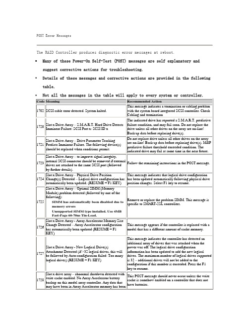
POST Error Messages(阵列卡错误代码)
Slot x drive array – redundant controller error
Replace controller or server motherboard.
1762
Redundant controller operation is not supported in this firmware version. Please remove redundant controller or upgrade controller firmware. (Controller is disabled until this problem is resolved.)
1726
Slot x Drive Array - Array Accelerator Memory Size Change Detected – Array Accelerator configuration has automatically been updated (RESUME = F1 KEY)
Details of these messages and corrective actions are provided in the following table.
Not all the messages in the table will apply to every system or controller.
This POST message should never occur unless the write cache is somehow enabled on a controller that does not have batteries.
1729
Slot 1 Drive Array - disk performance optimization scan in progress – RAID 4/5 performance may be higher after completion.
- 1、下载文档前请自行甄别文档内容的完整性,平台不提供额外的编辑、内容补充、找答案等附加服务。
- 2、"仅部分预览"的文档,不可在线预览部分如存在完整性等问题,可反馈申请退款(可完整预览的文档不适用该条件!)。
- 3、如文档侵犯您的权益,请联系客服反馈,我们会尽快为您处理(人工客服工作时间:9:00-18:30)。
3 Fault-Tolerant Adaptive Storage System 22 3.1 Small Load Implies Some Resiliency Against a Non-adaptive Adversary . . . 23 3.2 A Generic Scheme for a Fault-Tolerant Storage System With a Constant Blowup Ratio . . . . . . . . . . . . . . . . . . . . . . . . . . . . . . . . . . . 24 3.3 Adaptive Storage System Based on the ‘And-Or’ System . . . . . . . . . . . 25 3.3.1 Adaptive Read Strategy for Finding a Complete And Set. . . . . . . 25 3.3.2 Adaptive Read Strategy in the Presence of Faults. . . . . . . . . . . . 28 3.3.3 Dynamically Adjusting the Retrieval Scheme to the Number of Faults. 30 4 Dynamic Implementation of the And-Or Storage System 4.1 Some Properties of the Distance Halving Dynamic Network . . . . . . . . . . 4.2 Dynamic fault-tolerant Scheme . . . . . . . . . . . . . . . . . . . . . . . . . 4.2.1 Network Implementation of Storage and Retrieval . . . . . . . . . . . 32 34 35 36
Acknowledgements
I would like to thank my advisor Moni Naor for many useful conversations and for inspiring me with ideas. I am also very grateful for Moni’s help in turning my research results into a formal paper. I would like to thank Gera Weiss for many useful discussions and comments. Last but not least, I would like to thank Ilan Gronau for his extensive comments on a draft of this thesis, which led to significant improvements in the presentation and for many useful discussions. Finally I would like to thank all the colleagues and friends that made my time at the Weizmann Institute a great experience.
1
Contents
1 Introduction 1.1 Motivation . . . . . . . . . . . . . . . . . . . . 1.2 Definitions and Preliminaries . . . . . . . . . . 1.3 A Simple Example of a Fault-Tolerant Storage 1.4 Related Work . . . . . . . . . . . . . . . . . . 1.5 Results and Thesis Organization . . . . . . . . 1.5.1 Organization . . . . . . . . . . . . . . 5 5 6 8 8 10 11 13 13 17 20
2
5 The And-Or Quorum System In a Random Faults Model 5.1 Motivation and Definitions . . . . . . . . . . . . . . . . . . . . . 5.2 Algorithmic Probe Complexity of the And-Or Quorum System. 5.2.1 A Non-adaptive Algorithm. . . . . . . . . . . . . . . . . 5.2.2 An Adaptive Algorithm . . . . . . . . . . . . . . . . . . 5.3 The And-Or Quorum System on a Balanced Binary Tree . . . .
. . . . . .
. . . . . .
. . . . . .
2 Storage Systems with Non-Adaptive Retrieval 2.1 The Non-Adaptive Retrieval Model . . . . . . . . . . . . . . . . . . . . . . . 2.2 Read-Write Tradeoff of a Storage System . . . . . . . . . . . . . . . . . . . . 2.3 Bounding the Blowup-Ratio . . . . . . . . . . . . . . . . . . . . . . . . . . .
Abstract We deal with storage systems and quorum systems for a dynamic environment where servers may join and leave the system. We suggest a file storage system construction based on the √ √ ‘And-Or’ quorum system, that has a O( n) write complexity, O( n log n) read complexity and a constant data blowup-ratio, where n represents the number of processors in the network. Our construction is fault-tolerant against an adversary that can crash θ(n) processors of her choice while having slightly less adaptive queries than the reader. When both the legitimate reader and the adversary are nonadaptive we derive lower bounds on the read complexity, write complexity and data blowup ratio. We show these bounds are tight using a simple storage system construction, based on an -intersecting quorum system. In the random-fault model we show that the And-Or quorum system possesses optimal algorithmic probe complexity for both non-adaptive and adaptive readers. The non-adaptive √ algorithm for finding a live quorum achieves a O( n log n) algorithmic probe complexity which matches a lower bound of Naor and Wieder [20]. The adaptive algorithm finds a live √ quorum with a probe complexity which is linear in the size of a quorum (O( n)) and requires at most O(log log n) rounds. To the best of our knowledge, this is the smallest number of √ rounds in which a live quorum can be found, using only O( n) probes, for a system with an optimal load. Last we present an adaptation of the above storage system and a quorum system for a dynamic environment. Both are based on the And-Or tree and a dynamic overlay network that emulates the De-Bruijn network. These adaptations maintain the good properties of the above constructions (e.g., fault-tolerance, load and availability). The algorithms suggested for the maintenance of these dynamic data structures are strongly coupled with the routing scheme of the network. This fact enables the use of gossip protocols which saves in message complexity and keeps the protocols simple and local.