Alpha and IA64 Executive Summary
阿尔法拉維ATEX加权系統UltraPure輕芯说明书

The Alfa Laval weighing system is a complete solution offered for process weighing installation,where level measurement,mixing,filling,dosing or batching is required.The weighing solution is as standard delivered in three different accuracy ranges:0.10%,0.05% and0.025%with a total measuring range from0to4000kg.Each weighing system consists of1to4load cells and a weighing module. The weighing modules are available with both analog4-20mA output andfieldbus interface(PROFINET,Profibus DP or EtherNet IP).For high hygienic demands,the Alfa Laval load cells are supplied electropolished and hermetically sealed to IP68(laser welded).Capacitive measurement principle(patented)The Alfa Laval robust digital load cells are based on a patented capacitive measurement principle where a non-contacting capacitive sensor is mounted inside the load cell body.As the capacitive sensor is not in contact with the load cell body,the load cells are to a very high degree unaffected by overloads,sideloads,torsion and welding voltages.Therefore,a straightforward and hygienic mechanical installation of the load cells can be done without expensive and complicated mounting kits and overload protection devices.The electrical installation of the digital load cells is pure plug-and-play as the signal from the non-contacting capacitive sensor is directly converted,compensated and calibrated by a patented ASIC.The digital signal is transmitted as RS485data on a reliable RG-58single wire coaxial cable which may be up to50meters long.The factory calibration of the digital load cells is independent of the load cell cable length.Technical dataStainless steel enclsure..........IP68Stainless steel enclosure with panelmounted display...............IP64Measuring range:..............from0to4000kg dependingon system selection. Accuracy:...................0.10%,0.05%,0.025% Compensated temperature range:...-10to50°COverload and sideload:..........300%overload tolerance Power supply:................24VDC,±10%min.2A Certificates•CE marked•Calibration certificate(option)• 3.1B certificate(option)Mechanical dataWeight:BL-EX Load cell:.............. 2.3kgWeighing module:..............approx.0.5kgMaterials:Load cells:..................AISI316and17-4PH Mounting kit:.................AISI304/AISI316(weldingcylinder)Operating temperature range:BL-EX Load cells:..............-40to50°CWeighing modules:.............-10to50°CProtection class:Load cells:..................IP68Weighing modules:.............IP20SpecificationParameter Unit0.10%0.05%0.025% Rated capacity(Emax)per load cell kg10,20,50,100,150,250,500,1000 Safe overload limit%of E max300to1000Safe sideload limit%of E max500to2000Minimum dead load%of E max0Accuracy%of E max0.1000.0500.025 Repeatability%of E max0.0180.0150.010 Hysteresis%of E max0.0330.0200.017 Creep30min.%of E max0.0350.0250.017 Temperature effect on zero%/10°C0.0400.0300.016 Temperature effect on sensitivity%/10°C0.0400.0300.016 Deflection at Emax mm max.0.10Mesuring rate Hz up to1000Internal resolution Bit24Maximum cable length m100OptionsOUTPUT:4-20mAPROFINETEtherNet IPProfibus DPRS485Local weighing display:Alfa Laval weighing terminal(options)Load cell cable:6m ATEX coaxial RG58with BNC connector(option:10,20or50m)Mounting:Mounting kit for BL-EX beam load cellDimensional drawingsBL-EX Beam load cell0-100kg with mounting kitBL-EX Beam load cell100-1000kg with mounting kitLayout and electrical connection schematic of weighing modules:Profinet weighing module for4load cells(4XXXA)(external dimensions is the same for Profilbus DP and Ethernet IP4-20mA output weighing module for4load cells(4X79A)RS485interface module(when ordered with display(4X40A)ATEX POWER SUPPLY(4051A)14mm/5.51in128mm/5.4in116mm/4.57in11mm/.43in29 mm / 1.14 in60 mm / 2.36 inø4.5 mm / ø0.18 in66 mm / 2.60 in14mm/5.51in128mm/5.4in116mm/4.57in11mm/.43in29 mm / 1.14 in60 mm / 2.36 inø4.5 mm / ø0.18 in66 mm / 2.60 inInstallation in ATEX zonesLoad cells x=number of loadcellsATEX Power Supply Gnd-+Interfaces: EtherNet IPPROFINET EtherCAT Profibus DP Modbus TCP/IP DeviceNet RS485Power Supply +24Vdc,2AHAZARDOUS AREA SAFE AREASelection guideWhen configuring a weighing system,you need the following information:•ATEX application•Number of tank legs or supporting points•Total weight of tank incl.product in kg•Required output and/or local display•Required accuracy for the application(e.g.dosing,mixing,level measurement etc.)With this information,you are able tofind the configuration you need in the pricelist or in the online configuration tool:Step1:Is the weighing system used in ATEX zone1,2,21,22classified operation.Step2:Calculate the total weight of the tank inclusive the product in kg and round up to the nearest standard load cell system.Step3:Decide on accuracy required by the application-0.10%accuracy systems are suitable for mixing applications-0.05%accuracy systems are suitable for dosing applications-0.025%accuracy systems are suitable for very precise dosing and batching applicationsStep4:Decide on the output signal type and/or a local weighing display:-4-20mA-PROFINET-EtherNet IP-Profibus DP Step5:Decide on the length of the load cell cables(the length of the cable is can be shortened without the need for recalibration)-6m(standard)-10m-20m-50mStep6:Decide on if you need calibration certificateTheoretical statistical weighing system accuracy System range System rangeItem no.3supporting points4supporting pointsNumber ofloadcells andlc type in systemSystem type0.10%System type0.05%System type0.025%TE67WB9KXXXXXX0-60kg.(132lb)(3*20kg.lc)0.035kg.(0.076lb)0,017kg(0.038lb)0.009kg.(0.019lb) TE67WBBJXXXXXX0-80kg.(176lb)(4*20kg.lc)0.040kg.(0.088lb)0,020kg.(0.044lb)0.010kg.(0.022lb) TE67WBCKXXXXXX0-90kg.(198lb)(3*30kg.lc)0.052kg.(0.115lb)0,026kg.(0.057lb)0.013kg.(0.029lb) TE67WBEXXXXXXX0-120kg.(265lb)(4*30kg.lc)0.060kg.(0.132lb)0.030kg.(0.066lb)0.015kg.(0.033lb) TE67WBFKXXXXXX0-150kg.(331lb)(3*50kg.lc)0.087kg.(0.191lb)0.043kg.(0.095lb)0.022kg.(0.048lb) TE67WBGKXXXXXX0-200kg.(441lb)(4*50kg.lc)0.100kg.(0.220lb)0.050kg.(0.110lb)0.025kg.(0.055lb) TE67WBIXXXXXXXX0-300kg.(661lb)(3*100kg.lc)0.173kg.(0.382lb)0.087kg.(0.191lb)0.043kg.(0.095lb) TE67WBJXXXXXXXX0-400kg.(882lb)(14*100kg.lc)0.200kg.(0.441lb)0.100kg.(0.220lb)0.050kg.(0.110lb) TE67WBNKXXXXXX0-450kg.(992lb)(3*150kg.lc)0.260kg.(0.573lb)0.130kg.(0.211lb)0,065kg.(0.143lb) TE67WBOXXXXXXX0-600kg.(1323lb)(4*150kg lc)0.300kg.(0.661lb)0.150kg.(0.331lb)0.075kg.(0.165lb) TE67WBPXXXXXXX0-750kg.(1653lb)(3*250kg lc)0.433kg.(0.955lb)0.217kg.(0.477lb)0.108kg.(0.239lb) TE67WBLXXXXXXX0-1000kg.(2205lb)(4*250kg lc)0.500kg.(1.102lb)0.250kg.(0.551lb)0.125kg.(0.276lb) TE67WBSXXXXXXX0-1500kg.(3307lb)(3*500kg.lc)0.866kg.(1.909lb)0.433kg.(0.955lb)0,217kg.(0.477lb) TE67WBTXXXXXXX0-2000kg.(4409lb)(4*500kg.lc) 1.000kg.(2.205lb)0.500kg.(1.102lb)0.250kg.(0.551lb) TE67WBUKXXXXXX0-3000kg.(6614lb)(3*1000kg.lc) 1.732kg.(3.819lb)0.866kg.(1.909lb)N/ATE67WBVXXXXXXX0-4000kg.(8818lb)(4*1000kg.lc) 2.000kg.(4,409lb) 1.000kg.(2.205lb)N/ANote:All calculations are the theoretical worst case accuracy that can be obtained with the Alfa laval weighing system solutions.The presented data It is solely for Informational purpose,all real life accuracies is highly dependable of proper weighing system installationAlfa Laval reserves the right to change specifications without prior notification.How to contact Alfa Laval Contact details for all countriesare continually updated on our website.Please visit to access the information direct.A l f a L a v a l i s a t r a d e m a r k r e g i s t e r e d a n d o w n e d b y A l f a L a v a l C o r p o r a t e AB . 100001495e n 1906。
自动化测试系统顶层设计方法论说明书
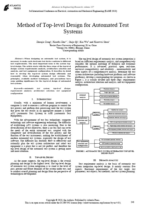
Method of Top-level Design for Automated TestSystemsZhenjie Zeng1, Xiaofei Zhu1,*, Shiju Qi1, Kai Wu2 and Xiaowei Shen11Rocket Force University of Engineering, Xi’an, China2Troops No. 96604, Beijing, China*Corresponding authorAbstract—When designing an automatic test system, it is necessary to make each electronic test device conform to different test requirements. The most important issue is the system top-level design. The article starts with the three steps of the top-level design: system requirements analysis, architecture selection and analysis, and test equipment configuration. It describes in detail how to develop the top-level system design efficiently and reasonably when developing automated test systems. The principles, available method techniques, and precautions have some guiding significance for the top-level design of automated test systems.Keywords—automatic test system; top-level design; requirements analysis; architecture selection; test equipment configurationI.I NTRODUCTIONUsually, with a minimum of human involvement, a computer is used to execute a software program to control the test process and perform data processing until the test system that gives the test results in an appropriate manner is called ATS (Automatic Test System) or ATE (Automatic Test Equipment). .With the advancement of test bus technology, computer technology and software engineering technology, the difficultyof establishing ATS systems is also increasing. Due to the diversification of test objectives, there is no bus that can cover the needs of the entire automated test, coupled with the complexity and diversification of the test process and the function of the test instruments, making the establishment of modern automated test systems, especially the design of test software. The difficulty has doubled. How to effectively and rationally plan the test system architecture and select test equipment is a place that is not yet perfect, and therefore the top level design of the automatic test system is getting more and more attention.II.T OP-LEVEL D ESIGNAs the name suggests, the top-level design is the overall planning and design at the highest level. The top-level design of automatic test system integration is to stand at the level of past, present and future demands of the system under test, and to conduct overall planning and design from the perspective of technological development.The top-level design of automatic test system integration is based on sufficient requirements analysis, and comprehensively considers the optimal matching of technical and economic performances. It is advanced, practical, open, real-time, universal (compatibility), and reliability. , maintainability and other aspects of a comprehensive analysis, determine the test system architecture (including hardware platforms and software platforms), develop a corresponding test program. As shown in Figure 1, it is usually divided into three steps: requirements analysis, architecture selection and analysis, and test equipment configuration.AemandanalysisArchitectureselection andanalysisTest equipmentselection andconfigurationFunctional AnalysisTarget signal typeMeasured parameter definitionTestability analysisTest method analysisInterface bus analysisHardware architecture analysisController selection and analysisHardwareplatformSoftware operating environment analysisOperating system selection and analysisDevelopment platform selection and analysisDatabase selection and analysisTest instrument (module) selectionUTT interface connection designSpecial parameters require processingSoftwareplatformFIGURE I. AUTOMATIC TEST SYSTEM INTEGRATION TOP LEVELDESIGN FLOWIII.D EMAND A NALYSISTest requirement analysis is the basis of automatic test system integration top-level design. It mainly contains five aspects: functional requirements of the test target, test parameters, test objects, test methods, and test system planning.3rd International Conference on Electrical, Automation and Mechanical Engineering (EAME 2018)A.Test Target Functional RequirementsThe different requirements of the test equipment working platform determine the test speed requirements, and also determine the different requirements of the online/offline test; the main control method and logic of the tested equipment determines the difference between the test procedures and methods; the input frequency of the tested equipment, Different parameters, such as amplitude and modulation method, determine the overall requirements for the operating frequency band, small signal level (minimum leakage), and waveform parameters of the automatic test system analog signal source; the output and content of the device under test determines the signal sampling of the automatic test system. The data acquisition method is different; the digital communication interface of the device under test determines that the digital communication interface that the automatic test system should have is different from the protocol; the testability interface of the device under test determines the final test capability and fault diagnosis ability of the automatic test system.B.Test ParametersThe test parameter analysis includes analysis: the form of the measured parameter (electrical or non-electrical, digital or analog, etc.), range and quantity; performance index (measurement accuracy and speed, etc.); the form and range of the excitation signal. In particular, when analyzing requirements for a top-level design of a general-purpose comprehensive automatic test system that is suitable for multiple systems, multiple protocols, and multiple equipment, comprehensive analysis is often required to integrate the test parameters.C.Test ObjectThe test objects vary widely. When analyzing the test objects, a comprehensive analysis must be performed in conjunction with the test system requirements of the test objects. In the face of a specific test object test system or subsystem, the description can use a variety of expressions to give different models of the test system at different levels of simplification, such as language descriptions, graphics, and mathematical formulas. As a simplified description of some test systems, their models merely express their basic characteristics, often ignoring irrelevant details in order to simplify their complexity. For a complex test object test system, a model is inevitably limited by some assumptions in its design and utility. These conditions often have some ambiguity and basically reflect an implicit conceptual idea. Therefore, when analyzing the requirements of a specific test object, it is usually necessary to establish a corresponding test system model.D.Test MethodsAccording to the functional requirements of the test target, a corresponding test method is formulated for the “face-to-face automatic test system” or “object-oriented automatic test system”.. E.Test System PlanningWhen developing an automated test system, it often takes a lot of time to complete the test-assisted tasks such as creating files and programming supporting test software. The test application software development platform can standardize all kinds of test processes and integrate an operating system that is suitable for various test and post-processing functions. It can help us to complete these test auxiliary work; therefore, we use this kind of test platform to conduct various tests. When testing, you can save a lot of time.IV.A RCHITECTURE S ELECTION AND A NALYSIS On the basis of sufficient requirements analysis, determining the architecture of the automated test system is the most critical step in the top-level design. That is how to determine the test plan from the perspective of the top-level design, and select the hardware platform and software platform architecture of the automatic test system, and the most important one is the selection of the test equipment digital communication interface bus.A.System Test Plan SelectionThe system test plan is the overall concept of product testing. It specifies the type of product testing, when (continuous or regular) testing, where (field or workshop, or which maintenance level), testing methods, and test methods used. The types of system test can be divided into: system-wide test and departmental system test, static test and dynamic test, online test and offline test, quantitative test and qualitative test, continuous test and periodic test, etc. The test level can be divided into three levels according to the location: production site, use site, and maintenance base. The test system (equipment) operating methods are generally:According to the use of the operation can be divided into three kinds of automatic, semi-automatic and artificial; according to the general degree of application can be divided into two kinds of special and general equipment; according to the association with the product can be divided into two kinds of BITE and external test equipment.Most of the test methods used in automated testing have so far been modeled on manual tests, from the measurement principles used, the testing techniques used, to the test procedures performed, except that computers were used instead of manual operations. As far as the characteristics and potential of automatic testing are concerned, fundamental reforms of the test plan are needed for future research.B.Selection of Test Equipment Digital CommunicationInterface Bus and ATS StructureThe development of automatic test systems has promoted the continuous emergence of various general-purpose test equipment interface buses and rapid technological advancement: from the early GPIB, CAMAC to the recent VXI, MXI, PCI, PCIe, PXI, PXIe, cPCI, MMS, IEEE1394 ( Firewire), USB, etc. Although technical characteristics are not the same, they are widely used.The structural elements of a modern automated test system are programmable test instruments, test controllers, interconnected standard digital interfaces, and software systems. At present, modern automatic testing has been widely used, and the test objects faced are large, complex, and diversified, making it impossible for an automatic test system based on any kind of bus technology to cover the needs of the entire test object.Multi-bus fusion automatic test system structure shown in Figure 2. It consists of test instruments, DUTs(design under test) and UUT(unit under test) interfaces, test controllers (computers), various general-purpose digital interface buses, and test software. The test controller is interconnected with the test instrument through the digital interface bus, and the device under test is connected to the input/output terminal of the test instrument through the UUT interface. The digital interface bus used may be GPIB, VXI, PXI, LXI, or even an internal computer bus (AT/EISA/PCI), or their convergence. Once the standard digital interface bus architecture used is determined, the automatic test system architecture is basically selected. In an automatic test system, regardless of the interface bus architecture, an external computer or built-in computer system can be selected as the test system controller. The choice of the test system controller should fully consider the optimal matching of technical and economic performance, and choose from real-time, practical, reliable, flexible and convenient.CAT test hostMaster control computerGPIB instrument PC card typeinstrumentVXIinstrumentPXIinstrumentUUT interfaceUUT……FIGURE II. MULTI-BUS FUSION AUTOMATIC TEST SYSTEMSTRUCTUREC.Test Software Platform Mode SelectionIn modern computer-based automated test systems, hardware is the foundation and software is the soul. Test software has increasingly become the main body of ATS, which determines the advanced nature, reliability, practicality, and real-time performance of the entire automated test system.The automatic test software platform mainly refers to the programming language and software support environment involved in the test application software design. It is an integrated software platform such as a computer operating system, a test programming language, a database software, and a program diagnosis software. The key element is Test programming language. Since the automatic test system was popularized and applied, there have been great developments in testing programming languages from low-level to high-level, to the current test application development environment.V.T EST E QUIPMENT C ONFIGURATION After the system structure of the test system is determined, the next task is to synthesize the test contents according to the requirements analysis, and to match the corresponding test equipment according to the test content requirements. There are three types of optional test equipment: general test equipment, special purpose equipment, and test interface adapter.A.Universal Test EquipmentThe universal test equipment includes a main box, a test controller, a main control interface, a zero slot controller, an instrument module, and a desktop instrument. The following factors should be considered when selecting the type of equipment: (1) The higher the degree of equipment automation, the shorter the time for detecting and isolating faults, and the less the manpower consumption, but the cost of test equipment will increase and more protection is needed. (2) Differences in capabilities between the two are to be considered when selecting a BIT (Built-in-Test) and an off-board automatic test equipment. (3) When the BIT is used in conjunction with the off-board automatic test, make full use of the BIT capability of each unit under test. (4) When selecting a dedicated or general-purpose device, it is necessary to consider that the special-purpose device is simple and convenient to use and has high efficiency, but the use range is narrow. (5) The main selection of instrument and equipment is based on the requirements of test parameters, characteristics of the signal to be measured, and range selection. When selecting the instrument module, pay attention to the size of the bus module, power, and number of slots.B.Special Purpose EquipmentWhen the test is not ready for selection, in addition to the above-mentioned common tests, when preparing for the following situations, it may be considered to develop or develop special purpose instrument (module) equipment. When the current product can not meet the test requirements, multiple instruments and equipments are required to complete the measurement together. However, the utilization rate of each instrument is very low or can be accomplished with one instrument. When the price is high and the utilization rate is low, the use of development or development is considered. Special purpose instrument.C.Test Interface Adapter DesignFor different test objects, the extraction and feeding of various test signals requires the design and manufacture of various test interfaces and special fixtures. In the automatic test system, especially the automatic test system assembly of complex electronic equipment, the requirements of the same type but different models and different test objects existuniversally, and often require the test system group to build a relatively universal automatic test platform. Through this platform, different test modules and test methods can be used to quickly and easily complete the automatic test system set-up (configuration) task for different test objects; however, the test interface and the dedicated test module cannot be matched and can only be tested according to the device under test. The test requires the development of a test interface adapter.VI.C ONCLUSIONThis article starts with the three steps of the top-level design: system requirements analysis, architecture selection and analysis, and test equipment configuration. It describes in detail how to perform top-level design efficiently and reasonably when developing automated test systems, and analyzes what the design must follow. Principles, methods, techniques, and precautions have certain guiding significance for the top-level design of automated test systems.R EFERENCES[1]LI Xing-shan, ZUO Yi, SUN Jie. Automatic Test System IntegrationTechnology[M]. Publishing House of Electronics Industry, 2004.[2]QIN Hong-lei, LU Hui et al. Automatic Test System. Beijing: HigherEducation Press, 2007[3]LIU Si-jiu, ZHANG Li-yong. Automatic Test System and VirtualInstrument. Beijing: Publishing House of Electronics Industry, 2009 [4]GU Zhi-yong, TENG Peng, HU Shi-guo, et al. Top-level design of ATSoverall plan for integrated helicopter display systems[J]. Electro-optics and Control, 2008, 15(11):59-62.[5]GU Ya-ping. Research on Top Design of VXI Bus TestingTechnology[J]. Electronic Testing, 1998(8):22-23.。
theiaR软件包用户指南说明书
Package‘theiaR’October14,2022Title Download and Manage Data from TheiaVersion0.4.0Description Provides a simple interface to search available data provided byTheia(<https://es.fr>),download it,and manage it.Data can be downloaded based on a search result or from a cartfile downloaded from Theia website.Language en-USDepends R(>=3.5)Imports askpass(>=1.1),httr(>=1.3),R6(>=2.3),raster(>=2.6),tools(>=3.5),XML(>=3.86)License GPL(>=3.0)URL https:///norival/theiaRBugReports https:///norival/theiaR/issuesEncoding UTF-8LazyData trueRoxygenNote7.1.1Suggests knitr,rmarkdown,gdalcubesCollate'TheiaAuth.R''TheiaTile.R''TheiaCollection.R''TheiaQuery.R''theiaR.R''utils.R'VignetteBuilder knitrNeedsCompilation noAuthor Xavier Laviron[aut,cre](<https:///0000-0002-9882-3253>) Maintainer Xavier Laviron<******************>Repository CRANDate/Publication2020-11-1909:30:02UTC12TheiaAuth R topics documented:TheiaAuth (2)TheiaCollection (3)TheiaQuery (5)theiaR (7)TheiaTile (7)Index9 TheiaAuth Authentication system to Theia websiteDescriptionGenerate and manage authentication to Theia website from login and password.It requests a token to download tiles when created and automatically request a new one when it has expired(after2h).It is used to download tiles from TheiaTile and TheiaCollection objects.Usagea<-TheiaAuth$new(auth.file)a$token()Argumentsa:A TheiaAuth objectauth.file The path to thefile containing login and password.It will be created if it does not exist.See‘Details‘for more informationsDetailsTheiaAuth$new(auth.file)Create a new instance of the classa$token()Return the current token or generate a next one if it has expiredThis class is used to manage authentication to Theia website,without intervention from the user.Login and password must be stored in a separate textfile with these two lines:login passwordFile content is read each time authentication is needed(to request a new token),so login and pass-word are not stored in R’s memory.If thisfile does not exist,R will prompt you to enter your login and password and will create thefile.Examples##Not run:#create an authentication objectmyauth<-TheiaAuth$new("path_to_auth_file.txt")#show the access token(and request a new one if needed)myauth$token##End(Not run)TheiaCollection A collection of tiles from TheiaDescriptionGenerate and manage collection of tiles from Theia.This collection can be created either from a cartfile(’.meta4’)downloaded from Theia website,from a TheiaQuery object or from a list of TheiaTile(not implemented yet).Usagec<-TheiaCollection$new(cart.path=NULL,tiles=NULL,query=NULL,dir.path=NULL,check=TRUE)quiet=TRUE)c$download(auth,overwrite=FALSE,check=TRUE,quiet=TRUE)c$check()c$statusc$extract(overwrite=FALSE,dest.dir=NULL)c$read(bands)c$as_gdalcube(out.file="gdalcube_collection.sqlite")Argumentsc:A TheiaCollection objectdir.path:The path to the directory containing zipfilescheck:Whether or not to check existingfiles on collection’s creationquiet:Control verbose outputtiles:A list of TheiaTile objectscart:An XML cart parsed from a’meta4’file downloaded from Theia ed only if Collection is created from a cartquery:A TheiaQuery object,used only if collection is created from a TheiaQuery object.Can also be a list with search terms.In this case,it will create a‘TheiaQuery‘object from it.See TheiaQuery for details on query syntaxauth:A character string giving thefile path to Theia credentials.Or a TheiaAuth objectoverwrite:Overwrite existing tiles(default to‘FALSE‘)bands:A character vector of bands to load from tilesout.file:Filename to store gdalcubes’image collectionDetailsTheiaCollection$new()Create a new instance of the classc$download(overwrite=FALSE,check=TRUE)Download the tiles of the collection and check the resultingfiles$ccheck()Check the tiles of the collectionc$status Return the status of each tile of the collectionc$extract(overwrite=FALSE,dest.dir=NULL)Extract archives to dest.dir if supplied,or to the same directory as the archives otherwisec$read(bands)Read requested bands,apply corrections on values(as specified in Theia’s product information),and return a list of RasterStack objects(one stack per tile)c$as_gdalcube(out.file)Create a‘gdalcubes‘image collection from downloaded tiles.See https:///appelmar/gdalcubes_R for more details.Examples#Create a collection from a query##Create a query to Theia database,looking for tiles from Sentinel2##satellite around Grenoble,between2018-07-01and2018-07-06.query<-list(collection="SENTINEL2",town="Grenoble",start.date="2018-07-01",end.date="2018-07-06")##Create a collecion of tiles from this querymycollection<-TheiaCollection$new(query=query,dir.path=".")print(mycollection)#Alternatively,you can create a collection from a cart file(that you can#download from Theia s website)cart.path<-system.file("extdata","cart.meta4",package="theiaR")mycollection<-TheiaCollection$new(cart.path=cart.path,dir.path=".")print(mycollection)##Not run:#Download the tiles in the collectionmycollection$download()##End(Not run)##Not run:#Finally,you can extract zip archives containing the tilesmycollection$extract(overwrite=FALSE)##End(Not run)TheiaQuery A query to the Theia websiteDescriptionGenerate an send a query to Theia web API to get and download tiles based on input given by the user.Usageq<-TheiaQuery$new(query)q$update_token()q$submit()Argumentsq:A TheiaQuery objectquery:list,the users’request,see‘Queries‘for more informationsDetailsTheiaQuery$new()Create a new instance of the class,parse‘query‘list and submit the query to Theia to retrievefiles catalogq$submit()Submit the query to Theia and get a list of tiles corresponding to search criteria QueriesSearch criteria are given with a‘list‘accepting thesefields:•collection:The collection to look for.Accepted values are:’SENTINEL2’,’LANDSAT’,’Landsat57’,’SpotWorldHeritage’,’Snow’.Defaults to’SENTINEL2’•platform:The platform to look for.Accepted values are:’LANDSAT5’,’LANDSAT7’,’LANDSAT8’,’SPOT1’,’SPOT2’,’SPOT3’,’SPOT4’,’SPOT5’,’SENTINEL2A’,’SEN-TINEL2B’•level:Processing level.Accepted values are:’LEVEL1C’,’LEVEL2A’,LEVEL3A’,’N2A’.Defaults to’LEVEL2A’(or’N2A’if querying Landsat57collection).•town:The location to look for.Give a common town name.•tile:The tile identifier to retrieve.•start.date:Thefirst date to look for(format:YYYY-MM-DD).•end.date:The last date to look for(format:YYYY-MM-DD).Must be after start.date.De-faults to today’s date.•latitude:The x coordinate of a point•longitude:The y coordinate of a point•latmin:The minimum latitude to search•latmax:The maximum latitude to search•lonmin:The minimum longitude to search•lonmax:The maximum longitude to search•orbit.number:The orbit number•rel.orbit.number:The relative orbit number•max.clouds:The maximum of cloud cover wanted(0-100)•max.records:The maximum of tiles to searchSee Alsohttps:///olivierhagolle/theia_download for an alternative download method based on Python.Inspiration for this function.Examples#Create a query to Theia database,looking for tiles from Sentinel2#satellite around Grenoble,between2018-07-01and2018-07-06.query<-list(collection="SENTINEL2",town="Grenoble",start.date="2018-07-01",end.date="2018-07-06")q<-TheiaQuery$new(query)#Show informations on found tilesprint(q$tiles)theiaR7 theiaR theiaR:search,download and manage theia dataDescriptionSearch,manage and download data from Theia websiteTheiaTile A tile from TheiaDescriptionGenerate and manage a tile from Theia(download,check,load).Usaget<-TheiaTile$new(file.path,url,file.hash,check=TRUE,quiet=TRUE)t$download(overwrite=FALSE,check=TRUE,quiet=TRUE)t$check()t$extract(overwrite=FALSE,dest.dir=NULL)t$read(bands)Argumentst:A TheiaTile objectfile.path:The path to the zipfile containing the tileurl:The url to download the tilefile.hash:The md5sum used to check the zipfilecheck:Whether or not to check existingfiles on tile’s creationquiet:Control verbose outputauth:A character string giving thefile path to Theia credentials.Or a TheiaAuth objectoverwrite:Overwrite existing tiles(default to‘FALSE‘)bands:A character vector of bands to load from tiles8TheiaTileDetailsTheiaTile$new(file.path,url,file.hash,check)Create a new instance of the classt$download(auth,overwrite=FALSE,check=TRUE)Download the tiles of the collection and check the resultingfilest$check()Check the tiles of the collectiont$extract(overwrite=FALSE,dest.dir=NULL)Extract archive to dest.dir if supplied,or to the same directory as the archive otherwiset$read(bands)Read requested bands,apply corrections on values(as specified in Theia’s product information),and return a RasterStackt$bands List bands available in the tileIndexTheiaAuth,2,4,7TheiaCollection,2,3TheiaQuery,3,4,5theiaR,7TheiaTile,2,3,79。
Probabilistic model checking of an anonymity system
Probabilistic Model Checking ofan Anonymity SystemVitaly ShmatikovSRI International333Ravenswood AvenueMenlo Park,CA94025U.S.A.shmat@AbstractWe use the probabilistic model checker PRISM to analyze the Crowds system for anonymous Web browsing.This case study demonstrates howprobabilistic model checking techniques can be used to formally analyze se-curity properties of a peer-to-peer group communication system based onrandom message routing among members.The behavior of group mem-bers and the adversary is modeled as a discrete-time Markov chain,and thedesired security properties are expressed as PCTL formulas.The PRISMmodel checker is used to perform automated analysis of the system and ver-ify anonymity guarantees it provides.Our main result is a demonstration ofhow certain forms of probabilistic anonymity degrade when group size in-creases or random routing paths are rebuilt,assuming that the corrupt groupmembers are able to identify and/or correlate multiple routing paths originat-ing from the same sender.1IntroductionFormal analysis of security protocols is a well-establishedfield.Model checking and theorem proving techniques[Low96,MMS97,Pau98,CJM00]have been ex-tensively used to analyze secrecy,authentication and other security properties ofprotocols and systems that employ cryptographic primitives such as public-key en-cryption,digital signatures,etc.Typically,the protocol is modeled at a highly ab-stract level and the underlying cryptographic primitives are treated as secure“black boxes”to simplify the model.This approach discovers attacks that would succeed even if all cryptographic functions were perfectly secure.Conventional formal analysis of security is mainly concerned with security against the so called Dolev-Yao attacks,following[DY83].A Dolev-Yao attacker is a non-deterministic process that has complete control over the communication net-work and can perform any combination of a given set of attacker operations,such as intercepting any message,splitting messages into parts,decrypting if it knows the correct decryption key,assembling fragments of messages into new messages and replaying them out of context,etc.Many proposed systems for anonymous communication aim to provide strong, non-probabilistic anonymity guarantees.This includes proxy-based approaches to anonymity such as the Anonymizer[Ano],which hide the sender’s identity for each message by forwarding all communication through a special server,and MIX-based anonymity systems[Cha81]that blend communication between dif-ferent senders and recipients,thus preventing a global eavesdropper from linking sender-recipient pairs.Non-probabilistic anonymity systems are amenable to for-mal analysis in the same non-deterministic Dolev-Yao model as used for verifica-tion of secrecy and authentication protocols.Existing techniques for the formal analysis of anonymity in the non-deterministic model include traditional process formalisms such as CSP[SS96]and a special-purpose logic of knowledge[SS99].In this paper,we use probabilistic model checking to analyze anonymity prop-erties of a gossip-based system.Such systems fundamentally rely on probabilistic message routing to guarantee anonymity.The main representative of this class of anonymity systems is Crowds[RR98].Instead of protecting the user’s identity against a global eavesdropper,Crowds provides protection against collaborating local eavesdroppers.All communication is routed randomly through a group of peers,so that even if some of the group members collaborate and share collected lo-cal information with the adversary,the latter is not likely to distinguish true senders of the observed messages from randomly selected forwarders.Conventional formal analysis techniques that assume a non-deterministic at-tacker in full control of the communication channels are not applicable in this case. Security properties of gossip-based systems depend solely on the probabilistic be-havior of protocol participants,and can be formally expressed only in terms of relative probabilities of certain observations by the adversary.The system must be modeled as a probabilistic process in order to capture its properties faithfully.Using the analysis technique developed in this paper—namely,formalization of the system as a discrete-time Markov chain and probabilistic model checking of2this chain with PRISM—we uncovered two subtle properties of Crowds that causedegradation of the level of anonymity provided by the system to the users.First,if corrupt group members are able to detect that messages along different routingpaths originate from the same(unknown)sender,the probability of identifyingthat sender increases as the number of observed paths grows(the number of pathsmust grow with time since paths are rebuilt when crowd membership changes).Second,the confidence of the corrupt members that they detected the correct senderincreases with the size of the group.Thefirstflaw was reported independently byMalkhi[Mal01]and Wright et al.[W ALS02],while the second,to the best ofour knowledge,was reported for thefirst time in the conference version of thispaper[Shm02].In contrast to the analysis by Wright et al.that relies on manualprobability calculations,we discovered both potential vulnerabilities of Crowds byautomated probabilistic model checking.Previous research on probabilistic formal models for security focused on(i)probabilistic characterization of non-interference[Gra92,SG95,VS98],and(ii)process formalisms that aim to faithfully model probabilistic properties of crypto-graphic primitives[LMMS99,Can00].This paper attempts to directly model andanalyze security properties based on discrete probabilities,as opposed to asymp-totic probabilities in the conventional cryptographic sense.Our analysis methodis applicable to other probabilistic anonymity systems such as Freenet[CSWH01]and onion routing[SGR97].Note that the potential vulnerabilities we discovered inthe formal model of Crowds may not manifest themselves in the implementationsof Crowds or other,similar systems that take measures to prevent corrupt routersfrom correlating multiple paths originating from the same sender.2Markov Chain Model CheckingWe model the probabilistic behavior of a peer-to-peer communication system as adiscrete-time Markov chain(DTMC),which is a standard approach in probabilisticverification[LS82,HS84,Var85,HJ94].Formally,a Markov chain can be definedas consisting in afinite set of states,the initial state,the transition relation such that,and a labeling functionfrom states to afinite set of propositions.In our model,the states of the Markov chain will represent different stages ofrouting path construction.As usual,a state is defined by the values of all systemvariables.For each state,the corresponding row of the transition matrix de-fines the probability distributions which govern the behavior of group members once the system reaches that state.32.1Overview of PCTLWe use the temporal probabilistic logic PCTL[HJ94]to formally specify properties of the system to be checked.PCTL can express properties of the form“under any scheduling of processes,the probability that event occurs is at least.”First,define state formulas inductively as follows:where atomic propositions are predicates over state variables.State formulas of the form are explained below.Define path formulas as follows:Unlike state formulas,which are simplyfirst-order propositions over a single state,path formulas represent properties of a chain of states(here path refers to a sequence of state space transitions rather than a routing path in the Crowds speci-fication).In particular,is true iff is true for every state in the chain;is true iff is true for all states in the chain until becomes true,and is true for all subsequent states;is true iff and there are no more than states before becomes true.For any state and path formula,is a state formula which is true iff state space paths starting from satisfy path formula with probability greater than.For the purposes of this paper,we will be interested in formulas of the form ,evaluated in the initial state.Here specifies a system con-figuration of interest,typically representing a particular observation by the adver-sary that satisfies the definition of a successful attack on the protocol.Property is a liveness property:it holds in iff will eventually hold with greater than probability.For instance,if is a state variable represent-ing the number of times one of the corrupt members received a message from the honest member no.,then holds in iff the prob-ability of corrupt members eventually observing member no.twice or more is greater than.Expressing properties of the system in PCTL allows us to reason formally about the probability of corrupt group members collecting enough evidence to success-fully attack anonymity.We use model checking techniques developed for verifica-tion of discrete-time Markov chains to compute this probability automatically.42.2PRISM model checkerThe automated analyses described in this paper were performed using PRISM,aprobabilistic model checker developed by Kwiatkowska et al.[KNP01].The toolsupports both discrete-and continuous-time Markov chains,and Markov decisionprocesses.As described in section4,we model probabilistic peer-to-peer com-munication systems such as Crowds simply as discrete-time Markov chains,andformalize their properties in PCTL.The behavior of the system processes is specified using a simple module-basedlanguage inspired by Reactive Modules[AH96].State variables are declared in thestandard way.For example,the following declarationdeliver:bool init false;declares a boolean state variable deliver,initialized to false,while the followingdeclarationconst TotalRuns=4;...observe1:[0..TotalRuns]init0;declares a constant TotalRuns equal to,and then an integer array of size,indexed from to TotalRuns,with all elements initialized to.State transition rules are specified using guarded commands of the form[]<guard>-><command>;where<guard>is a predicate over system variables,and<command>is the tran-sition executed by the system if the guard condition evaluates to mandoften has the form<expression>...<expression>, which means that in the next state(i.e.,that obtained after the transition has beenexecuted),state variable is assigned the result of evaluating arithmetic expres-sion<expression>If the transition must be chosen probabilistically,the discrete probability dis-tribution is specified as[]<guard>-><prob1>:<command1>+...+<probN>:<commandN>;Transition represented by command is executed with probability prob,and prob.Security properties to be checked are stated as PCTL formulas (see section2.1).5Given a formal system specification,PRISM constructs the Markov chain and determines the set of reachable states,using MTBDDs and BDDs,respectively. Model checking a PCTL formula reduces to a combination of reachability-based computation and solving a system of linear equations to determine the probability of satisfying the formula in each reachable state.The model checking algorithms employed by PRISM include[BdA95,BK98,Bai98].More details about the im-plementation and operation of PRISM can be found at http://www.cs.bham. /˜dxp/prism/and in[KNP01].Since PRISM only supports model checking offinite DTMC,in our case study of Crowds we only analyze anonymity properties offinite instances of the system. By changing parameters of the model,we demonstrate how anonymity properties evolve with changes in the system configuration.Wright et al.[W ALS02]investi-gated related properties of the Crowds system in the general case,but they do not rely on tool support and their analyses are manual rather than automated.3Crowds Anonymity SystemProviding an anonymous communication service on the Internet is a challenging task.While conventional security mechanisms such as encryption can be used to protect the content of messages and transactions,eavesdroppers can still observe the IP addresses of communicating computers,timing and frequency of communi-cation,etc.A Web server can trace the source of the incoming connection,further compromising anonymity.The Crowds system was developed by Reiter and Ru-bin[RR98]for protecting users’anonymity on the Web.The main idea behind gossip-based approaches to anonymity such as Crowds is to hide each user’s communications by routing them randomly within a crowd of similar users.Even if an eavesdropper observes a message being sent by a particular user,it can never be sure whether the user is the actual sender,or is simply routing another user’s message.3.1Path setup protocolA crowd is a collection of users,each of whom is running a special process called a jondo which acts as the user’s proxy.Some of the jondos may be corrupt and/or controlled by the adversary.Corrupt jondos may collaborate and share their obser-vations in an attempt to compromise the honest users’anonymity.Note,however, that all observations by corrupt group members are local.Each corrupt member may observe messages sent to it,but not messages transmitted on the links be-tween honest jondos.An honest crowd member has no way of determining whether6a particular jondo is honest or corrupt.The parameters of the system are the total number of members,the number of corrupt members,and the forwarding probability which is explained below.To participate in communication,all jondos must register with a special server which maintains membership information.Therefore,every member of the crowd knows identities of all other members.As part of the join procedure,the members establish pairwise encryption keys which are used to encrypt pairwise communi-cation,so the contents of the messages are secret from an external eavesdropper.Anonymity guarantees provided by Crowds are based on the path setup pro-tocol,which is described in the rest of this section.The path setup protocol is executed each time one of the crowd members wants to establish an anonymous connection to a Web server.Once a routing path through the crowd is established, all subsequent communication between the member and the Web server is routed along it.We will call one run of the path setup protocol a session.When crowd membership changes,the existing paths must be scrapped and a new protocol ses-sion must be executed in order to create a new random routing path through the crowd to the destination.Therefore,we’ll use terms path reformulation and proto-col session interchangeably.When a user wants to establish a connection with a Web server,its browser sends a request to the jondo running locally on her computer(we will call this jondo the initiator).Each request contains information about the intended desti-nation.Since the objective of Crowds is to protect the sender’s identity,it is not problematic that a corrupt router can learn the recipient’s identity.The initiator starts the process of creating a random path to the destination as follows: The initiator selects a crowd member at random(possibly itself),and for-wards the request to it,encrypted by the corresponding pairwise key.We’ll call the selected member the forwarder.The forwarderflips a biased coin.With probability,it delivers the request directly to the destination.With probability,it selects a crowd member at random(possibly itself)as the next forwarder in the path,and forwards the request to it,re-encrypted with the appropriate pairwise key.The next forwarder then repeats this step.Each forwarder maintains an identifier for the created path.If the same jondo appears in different positions on the same path,identifiers are different to avoid infinite loops.Each subsequent message from the initiator to the destination is routed along this path,i.e.,the paths are static—once established,they are not altered often.This is necessary to hinder corrupt members from linking multiple7paths originating from the same initiator,and using this information to compromise the initiator’s anonymity as described in section3.2.3.3.2Anonymity properties of CrowdsThe Crowds paper[RR98]describes several degrees of anonymity that may be provided by a communication system.Without using anonymizing techniques, none of the following properties are guaranteed on the Web since browser requests contain information about their source and destination in the clear.Beyond suspicion Even if the adversary can see evidence of a sent message,the real sender appears to be no more likely to have originated it than any other potential sender in the system.Probable innocence The real sender appears no more likely to be the originator of the message than to not be the originator,i.e.,the probability that the adversary observes the real sender as the source of the message is less thanupper bound on the probability of detection.If the sender is observed by the adversary,she can then plausibly argue that she has been routing someone else’s messages.The Crowds paper focuses on providing anonymity against local,possibly co-operating eavesdroppers,who can share their observations of communication in which they are involved as forwarders,but cannot observe communication involv-ing only honest members.We also limit our analysis to this case.3.2.1Anonymity for a single routeIt is proved in[RR98]that,for any given routing path,the path initiator in a crowd of members with forwarding probability has probable innocence against collaborating crowd members if the following inequality holds:(1)More formally,let be the event that at least one of the corrupt crowd members is selected for the path,and be the event that the path initiator appears in8the path immediately before a corrupt crowd member(i.e.,the adversary observes the real sender as the source of the messages routed along the path).Condition 1guarantees thatproving that,given multiple linked paths,the initiator appears more often as a sus-pect than a random crowd member.The automated analysis described in section6.1 confirms and quantifies this result.(The technical results of[Shm02]on which this paper is based had been developed independently of[Mal01]and[W ALS02],be-fore the latter was published).In general,[Mal01]and[W ALS02]conjecture that there can be no reliable anonymity method for peer-to-peer communication if in order to start a new communication session,the initiator must originate thefirst connection before any processing of the session commences.This implies that anonymity is impossible in a gossip-based system with corrupt routers in the ab-sence of decoy traffic.In section6.3,we show that,for any given number of observed paths,the adversary’s confidence in its observations increases with the size of the crowd.This result contradicts the intuitive notion that bigger crowds provide better anonymity guarantees.It was discovered by automated analysis.4Formal Model of CrowdsIn this section,we describe our probabilistic formal model of the Crowds system. Since there is no non-determinism in the protocol specification(see section3.1), the model is a simple discrete-time Markov chain as opposed to a Markov deci-sion process.In addition to modeling the behavior of the honest crowd members, we also formalize the adversary.The protocol does not aim to provide anonymity against global eavesdroppers.Therefore,it is sufficient to model the adversary as a coalition of corrupt crowd members who only have access to local communication channels,i.e.,they can only make observations about a path if one of them is se-lected as a forwarder.By the same token,it is not necessary to model cryptographic functions,since corrupt members know the keys used to encrypt peer-to-peer links in which they are one of the endpoints,and have no access to links that involve only honest members.The modeling technique presented in this section is applicable with minor mod-ifications to any probabilistic routing system.In each state of routing path construc-tion,the discrete probability distribution given by the protocol specification is used directly to define the probabilistic transition rule for choosing the next forwarder on the path,if any.If the protocol prescribes an upper bound on the length of the path(e.g.,Freenet[CSWH01]),the bound can be introduced as a system parameter as described in section4.2.3,with the corresponding increase in the size of the state space but no conceptual problems.Probabilistic model checking can then be used to check the validity of PCTL formulas representing properties of the system.In the general case,forwarder selection may be governed by non-deterministic10runCount goodbad lastSeen observelaunchnewstartrundeliver recordLast badObserve4.2Model of honest members4.2.1InitiationPath construction is initiated as follows(syntax of PRISM is described in section 2.2):[]launch->runCount’=TotalRuns&new’=true&launch’=false;[]new&(runCount>0)->(runCount’=runCount-1)&new’=false&start’=true;[]start->lastSeen’=0&deliver’=false&run’=true&start’=false;4.2.2Forwarder selectionThe initiator(i.e.,thefirst crowd member on the path,the one whose identity must be protected)randomly chooses thefirst forwarder from among all group mem-bers.We assume that all group members have an equal probability of being chosen, but the technique can support any discrete probability distribution for choosing for-warders.Forwarder selection is a single step of the protocol,but we model it as two probabilistic state transitions.Thefirst determines whether the selected forwarder is honest or corrupt,the second determines the forwarder’s identity.The randomly selected forwarder is corrupt with probability badCbe next on the path.Any of the honest crowd members can be selected as the forwarder with equal probability.To illustrate,for a crowd with10honest members,the following transition models the second step of forwarder selection: []recordLast&CrowdSize=10->0.1:lastSeen’=0&run’=true&recordLast’=false+0.1:lastSeen’=1&run’=true&recordLast’=false+...0.1:lastSeen’=9&run’=true&recordLast’=false;According to the protocol,each honest crowd member must decide whether to continue building the path byflipping a biased coin.With probability,the forwarder selection transition is enabled again and path construction continues, and with probability the path is terminated at the current forwarder,and all requests arriving from the initiator along the path will be delivered directly to the recipient.[](good&!deliver&run)->//Continue path constructionPF:good’=false+//Terminate path constructionnotPF:deliver’=true;The specification of the Crowds system imposes no upper bound on the length of the path.Moreover,the forwarders are not permitted to know their relative position on the path.Note,however,that the amount of information about the initiator that can be extracted by the adversary from any path,or anyfinite number of paths,isfinite(see sections4.3and4.5).In systems such as Freenet[CSWH01],requests have a hops-to-live counter to prevent infinite paths,except with very small probability.To model this counter,we may introduce an additional state variable pIndex that keeps track of the length of the path constructed so far.The path construction transition is then coded as follows://Example with Hops-To-Live//(NOT CROWDS)////Forward with prob.PF,else deliver13[](good&!deliver&run&pIndex<MaxPath)->PF:good’=false&pIndex’=pIndex+1+notPF:deliver’=true;//Terminate if reached MaxPath,//but sometimes not//(to confuse adversary)[](good&!deliver&run&pIndex=MaxPath)->smallP:good’=false+largeP:deliver’=true;Introduction of pIndex obviously results in exponential state space explosion, decreasing the maximum system size for which model checking is feasible.4.2.4Transition matrix for honest membersTo summarize the state space of the discrete-time Markov chain representing cor-rect behavior of protocol participants(i.e.,the state space induced by the abovetransitions),let be the state in which links of the th routing path from the initiator have already been constructed,and assume that are the honestforwarders selected for the path.Let be the state in which path constructionhas terminated with as thefinal path,and let be an auxiliary state. Then,given the set of honest crowd members s.t.,the transi-tion matrix is such that,,(see section4.2.2),i.e.,the probability of selecting the adversary is equal to the cumulative probability of selecting some corrupt member.14This abstraction does not limit the class of attacks that can be discovered using the approach proposed in this paper.Any attack found in the model where indi-vidual corrupt members are kept separate will be found in the model where their capabilities are combined in a single worst-case adversary.The reason for this is that every observation made by one of the corrupt members in the model with separate corrupt members will be made by the adversary in the model where their capabilities are combined.The amount of information available to the worst-case adversary and,consequently,the inferences that can be made from it are at least as large as those available to any individual corrupt member or a subset thereof.In the adversary model of[RR98],each corrupt member can only observe its local network.Therefore,it only learns the identity of the crowd member imme-diately preceding it on the path.We model this by having the corrupt member read the value of the lastSeen variable,and record its observations.This cor-responds to reading the source IP address of the messages arriving along the path. For example,for a crowd of size10,the transition is as follows:[]lastSeen=0&badObserve->observe0’=observe0+1&deliver’=true&run’=true&badObserve’=false;...[]lastSeen=9&badObserve->observe9’=observe9+1&deliver’=true&run’=true&badObserve’=false;The counters observe are persistent,i.e.,they are not reset for each session of the path setup protocol.This allows the adversary to accumulate observations over several path reformulations.We assume that the adversary can detect when two paths originate from the same member whose identity is unknown(see sec-tion3.2.2).The adversary is only interested in learning the identity of thefirst crowd mem-ber in the path.Continuing path construction after one of the corrupt members has been selected as a forwarder does not provide the adversary with any new infor-mation.This is a very important property since it helps keep the model of the adversaryfinite.Even though there is no bound on the length of the path,at most one observation per path is useful to the adversary.To simplify the model,we as-sume that the path terminates as soon as it reaches a corrupt member(modeled by deliver’=true in the transition above).This is done to shorten the average path length without decreasing the power of the adversary.15Each forwarder is supposed toflip a biased coin to decide whether to terminate the path,but the coinflips are local to the forwarder and cannot be observed by other members.Therefore,honest members cannot detect without cooperation that corrupt members always terminate paths.In any case,corrupt members can make their observable behavior indistinguishable from that of the honest members by continuing the path with probability as described in section4.2.3,even though this yields no additional information to the adversary.4.4Multiple pathsThe discrete-time Markov chain defined in sections4.2and4.3models construc-tion of a single path through the crowd.As explained in section3.2.2,paths have to be reformulated periodically.The decision to rebuild the path is typically made according to a pre-determined schedule,e.g.,hourly,daily,or once enough new members have asked to join the crowd.For the purposes of our analysis,we sim-ply assume that paths are reformulated somefinite number of times(determined by the system parameter=TotalRuns).We analyze anonymity properties provided by Crowds after successive path reformulations by considering the state space produced by successive execu-tions of the path construction protocol described in section4.2.As explained in section4.3,the adversary is permitted to combine its observations of some or all of the paths that have been constructed(the adversary only observes the paths for which some corrupt member was selected as one of the forwarders).The adversary may then use this information to infer the path initiator’s identity.Because for-warder selection is probabilistic,the adversary’s ability to collect enough informa-tion to successfully identify the initiator can only be characterized probabilistically, as explained in section5.4.5Finiteness of the adversary’s state spaceThe state space of the honest members defined by the transition matrix of sec-tion4.2.4is infinite since there is no a priori upper bound on the length of each path.Corrupt members,however,even if they collaborate,can make at most one observation per path,as explained in section4.3.As long as the number of path reformulations is bounded(see section4.4),only afinite number of paths will be constructed and the adversary will be able to make only afinite number of observa-tions.Therefore,the adversary only needsfinite memory and the adversary’s state space isfinite.In general,anonymity is violated if the adversary has a high probability of making a certain observation(see section5).Tofind out whether Crowds satisfies16。
SUN(oracle)、IBMIAX、HPUX小型机的比较资料

SUN(oracle)、IBM、HP小型机的比较资料---solaris、AIX、HP-UX 、CompaqTru64 UnixSun(Oracle) Solaris目前状况:好当前版本:Solaris 10 (x86)历史版本:Solaris 10 SunOS 5.10 2005年1月31日Solaris 9 SunOS 5.9 2002年5月22日Solaris 8 SunOS 5.8 200年2月Solaris 7 SunOS 5.7 1998年11月Solaris 2.6 SunOS 5.6 1997年7月Solaris 2.5.1 SunOS 5.5.1 1996年5月Solaris 2.5 SunOS 5.5 1995年11月主要产品有基于Ultra SPARC 和AMD Opteron 处理器的系列服务器、工作站,Sun Ray 桌面系统、Storage Tek 存储设备等硬件系统,Solaris和Java软件,以及Sun Grid等各类服务,并以其高度灵活性、缩放性、安全性和可用性等优异特性赢得全球各行业客户的青睐。
2005年12月,Sun基于其突破性“酷线程”专利技术推出新的“绿色经济型”服务器产品线,开启了网络计算的新时代。
硬件平台:Sun Sparc、Intel PC工作站和服务器软件:solaris、oracle、java、Mysql支持架构:Solaris支持多种系统架构SPARC、x86和x64。
x64即AMD64及EMT64处理器遵循标准:Unix 98优势:其光辉的市场业绩使Solaris成为了事实上的Unix;Sparc和Intel版是同一个操作系统;对于基于Unix的商业应用系统,Solaris可以提供最广泛的支持。
前景展望:牢固的市场和及时的开发,使得Sun身处领先的位置,Solaris取得了领先的位置是因为Sun保证了所有的应用系统都可以在其上运行。
Sun的顾客从它的训练有素的员工处获益。
ACM的论文写作格式标准
ACM Word Template for SIG Site1st Author1st author's affiliation1st line of address2nd line of address Telephone number, incl. country code 1st author's E-mail address2nd Author2nd author's affiliation1st line of address2nd line of addressTelephone number, incl. country code2nd E-mail3rd Author3rd author's affiliation1st line of address2nd line of addressTelephone number, incl. country code3rd E-mailABSTRACTA s network speed continues to grow, new challenges of network processing is emerging. In this paper we first studied the progress of network processing from a hardware perspective and showed that I/O and memory systems become the main bottlenecks of performance promotion. Basing on the analysis, we get the conclusion that conventional solutions for reducing I/O and memory accessing latencies are insufficient for addressing the problems.Motivated by the studies, we proposed an improved DCA combined with INIC solution which has creations in optimized architectures, innovative I/O data transferring schemes and improved cache policies. Experimental results show that our solution reduces 52.3% and 14.3% cycles on average for receiving and transmitting respectively. Also I/O and memory traffics are significantly decreased. Moreover, an investigation to the behaviors of I/O and cache systems for network processing is performed. And some conclusions about the DCA method are also presented.KeywordsKeywords are your own designated keywords.1.INTRODUCTIONRecently, many researchers found that I/O system becomes the bottleneck of network performance promotion in modern computer systems [1][2][3]. Aim to support computing intensive applications, conventional I/O system has obvious disadvantages for fast network processing in which bulk data transfer is performed. The lack of locality support and high latency are the two main problems for conventional I/O system, which have been wildly discussed before [2][4].To overcome the limitations, an effective solution called Direct Cache Access (DCA) is suggested by INTEL [1]. It delivers network packages from Network Interface Card (NIC) into cache instead of memory, to reduce the data accessing latency. Although the solution is promising, it is proved that DCA is insufficient to reduce the accessing latency and memory traffic due to many limitations [3][5]. Another effective solution to solve the problem is Integrated Network Interface Card (INIC), which is used in many academic and industrial processor designs [6][7]. INIC is introduced to reduce the heavy burden for I/O registers access in Network Drivers and interruption handling. But recent report [8] shows that the benefit of INIC is insignificant for the state of the art 10GbE network system.In this paper, we focus on the high efficient I/O system design for network processing in general-purpose-processor (GPP). Basing on the analysis of existing methods, we proposed an improved DCA combined with INIC solution to reduce the I/O related data transfer latency.The key contributions of this paper are as follows:▪Review the network processing progress from a hardware perspective and point out that I/O and related last level memory systems have became the obstacle for performance promotion.▪Propose an improved DCA combined with INIC solution for I/O subsystem design to address the inefficient problem of a conventional I/O system.▪Give a framework of the improved I/O system architecture and evaluate the proposed solution with micro-benchmarks.▪Investigate I/O and Cache behaviors in the network processing progress basing on the proposed I/O system.The paper is organized as follows. In Section 2, we present the background and motivation. In Section 3, we describe the improved DCA combined INIC solution and give a framework of the proposed I/O system implementation. In Section 4, firstly we give the experiment environment and methods, and then analyze the experiment results. In Section 5, we show some related works. Finally, in Section 6, we carefully discuss our solutions with many existing technologies, and then draw some conclusions.2.Background and MotivationIn this section, firstly we revise the progress of network processing and the main network performance improvement bottlenecks nowadays. Then from the perspective of computer architecture, a deep analysis of network system is given. Also the motivation of this paper is presented.2.1Network processing reviewFigure 1 illustrates the progress of network processing. Packages from physical line are sampled by Network Interface Card (NIC). NIC performs the address filtering and stream control operations, then send the frames to the socket buffer and notifies OS to invoke network stack processing by interruptions. When OS receives the interruptions, the network stack accesses the data in socket buffer and calculates the checksum. Protocol specific operations are performed layer by layer in stack processing. Finally, data is transferred from socket buffer to the user buffer depended on applications. Commonly this operation is done by memcpy, a system function in OS.Figure 1. Network Processing FlowThe time cost of network processing can be mainly broke down into following parts: Interruption handling, NIC driver, stack processing, kernel routine, data copy, checksum calculation and other overheads. The first 4 parts are considered as packet cost, which means the cost scales with the number of network packets. The rests are considered as bit cost (also called data touch cost), which means the cost is in proportion to the total I/O data size. The proportion of the costs highly depends on the hardware platform and the nature of applications. There are many measurements and analyses about network processing costs [9][10]. Generally, the kernel routine cost ranges from 10% - 30% of the total cycles; the driver and interruption handling costs range from 15% - 35%; the stack processing cost ranges from 7% - 15%; and data touch cost takes up 20% - 35%. With the development of high speed network (e.g. 10/40 Gbps Ethernet), an increasing tendency for kernel routines, driver and interruption handling costs is observed [3].2.2 MotivationTo reveal the relationship among each parts of network processing, we investigate the corresponding hardware operations. From the perspective of computerhardware architecture, network system performance is determined by three domains: CPU speed, Memory speed and I/O speed. Figure 2 depicts the relationship.Figure 2. Network xxxxObviously, the network subsystem can achieve its maximal performance only when the three domains above are in balance. It means that the throughput or bandwidth ofeach hardware domain should be equal with others. Actually this is hard for hardware designers, because the characteristics and physical implementation technologies are different for CPU, Memory and I/O system (chipsets) fabrication. The speed gap between memory and CPU – a.k.a “the memory wall” – has been paid special attention for more than ten years, but still it is not well addressed. Also the disparity between the data throughput in I/O system and the computing capacity provided by CPU has been reported in recent years [1][2].Meanwhile, it is obvious that the major time costs of network processing mentioned above are associated with I/O and Memory speeds, e.g. driver processing, interruption handling, and memory copy costs. The most important nature of network processing is the “producer -consumer locality” between every two consecutive steps of the processing flow. That means the data produced in one hardware unit will be immediately accessed by another unit, e.g. the data in memory which transported from NIC will be accessed by CPU soon. However for conventional I/O and memory systems, the data transfer latency is high and the locality is not exploited.Basing on the analysis discussed above, we get the observation that the I/O and Memory systems are the limitations for network processing. Conventional DCA or INIC cannot successfully address this problem, because it is in-efficient in either I/O transfer latency or I/O data locality utilization (discussed in section 5). To diminish these limitations, we present a combined DCA with INIC solution. The solution not only takes the advantages of both method but also makes many improvements in memory system polices and software strategies.3. Design MethodologiesIn this section, we describe the proposed DCA combined with INIC solution and give a framework of the implementation. Firstly, we present the improved DCA technology and discuss the key points of incorporating it into I/O and Memory systems design. Then, the important software data structures and the details of DCA scheme are given. Finally, we introduce the system interconnection architecture and the integration of NIC.3.1 Improved DCAIn the purpose of reducing data transfer latency and memory traffic in system, we present an improved Direct Cache Access solution. Different with conventional DCA scheme, our solution carefully consider the following points. The first one is cache coherence. Conventionally, data sent from device by DMA is stored in memory only. And for the same address, a different copy of data is stored in cache which usually needs additional coherent unit to perform snoop operation [11]; but when DCA is used, I/O data and CPU data are both stored in cache with one copy for one memory address, shown in figure 4. So our solution modifies the cache policy, which eliminated the snoopingoperations. Coherent operation can be performed by software when needed. This will reduce much memory traffic for the systems with coherence hardware [12].I/O write *(addr) = bCPU write *(addr) = aCacheCPU write *(addr) = a I/O write with DCA*(addr) = bCache(a) cache coherance withconventional I/O(b) cache coherance withDCA I/OFigure 3. xxxxThe second one is cache pollution. DCA is a mixed blessing to CPU: On one side, it accelerates the data transfer; on the other side, it harms the locality of other programs executed in CPU and causes cache pollution. Cache pollution is highly depended on the I/O data size, which is always quite large. E.g. one Ethernet package contains a maximal 1492 bytes normal payload and a maximal 65536 bytes large payload for Large Segment Offload (LSO). That means for a common network buffer (usually 50 ~ 400 packages size), a maximal size range from 400KB to 16MB data is sent to cache. Such big size of data will cause cache performance drop dramatically. In this paper, we carefully investigate the relationship between the size of I/O data sent by DCA and the size of cache system. To achieve the best cache performance, a scheme of DCA is also suggested in section 4. Scheduling of the data sent with DCA is an effective way to improve performance, but it is beyond the scope of this paper.The third one is DCA policy. DCA policy refers the determination of when and which part of the data is transferred with DCA. Obviously, the scheme is application specific and varies with different user targets. In this paper, we make a specific memory address space in system to receive the data transferred with DCA. The addresses of the data should be remapped to that area by user or compilers.3.2 DCA Scheme and detailsTo accelerate network processing, many important software structures used in NIC driver and the stack are coupled with DCA. NIC Descriptors and the associated data buffers are paid special attention in our solution. The former is the data transfer interface between DMA and CPU, and the later contains the packages. For farther research, each package stored in buffer is divided into the header and the payload. Normally the headers are accessed by protocols frequently, but the payload is accessed only once or twice (usually performed as memcpy) in modern network stack and OS. The details of the related software data structures and the network processing progress can be found in previous works [13].The progress of transfer one package from NIC to the stack with the proposed solution is illustrated in Table 1. All the accessing latency parameters in Table 1 are based on a state of the art multi-core processor system [3]. One thing should be noticed is that the cache accessing latency from I/O is nearly the same with that from CPU. But the memory accessing latency from I/O is about 2/3 of that from CPU due to the complex hardware hierarchy above the main memory.Table 1. Table captions should be placed above the tabletransfer.We can see that DCA with INIC solution saves above 95% CPU cycles in theoretical and avoid all the traffic to memory controller. In this paper, we transfer the NIC Descriptors and the data buffers including the headers and payload with DCA to achieve the best performance. But when cache size is small, only transfer the Descriptors and the headers with DCA is an alternative solution.DCA performance is highly depended on system cache policy. Obviously for cache system, write-back with write-allocate policy can help DCA achieves better performance than write-through with write non-allocate policy. Basing on the analysis in section 3.1, we do not use the snooping cache technology to maintain the coherence with memory. Cache coherence for other non-DCA I/O data transfer is guaranteed by software.3.3 On-chip network and integrated NICFootnotes should be Times New Roman 9-point, and justified to the full width of the column.Use the “ACM Reference format” for references – that is, a numbered list at the end of the article, ordered alphabetically and formatted accordingly. See examples of some typical reference types, in the new “ACM Reference format”, at the end of this document. Within this template, use the style named referencesfor the text. Acceptable abbreviations, for journal names, can be found here: /reference/abbreviations/. Word may try to automatically ‘underline’ hotlinks in your references, the correct style is NO underlining.The references are also in 9 pt., but that section (see Section 7) is ragged right. References should be published materials accessible to the public. Internal technical reports may be cited only if they are easily accessible (i.e. you can give the address to obtain thereport within your citation) and may be obtained by any reader. Proprietary information may not be cited. Private communications should be acknowledged, not referenced (e.g., “[Robertson, personal communication]”).3.4Page Numbering, Headers and FootersDo not include headers, footers or page numbers in your submission. These will be added when the publications are assembled.4.FIGURES/CAPTIONSPlace Tables/Figures/Images in text as close to the reference as possible (see Figure 1). It may extend across both columns to a maximum width of 17.78 cm (7”).Captions should be Times New Roman 9-point bold. They should be numbered (e.g., “Table 1” or “Figure 2”), please note that the word for Table and Figure are spelled out. Figure’s captions should be centered beneath the image or picture, and Table captions should be centered above the table body.5.SECTIONSThe heading of a section should be in Times New Roman 12-point bold in all-capitals flush left with an additional 6-points of white space above the section head. Sections and subsequent sub- sections should be numbered and flush left. For a section head and a subsection head together (such as Section 3 and subsection 3.1), use no additional space above the subsection head.5.1SubsectionsThe heading of subsections should be in Times New Roman 12-point bold with only the initial letters capitalized. (Note: For subsections and subsubsections, a word like the or a is not capitalized unless it is the first word of the header.)5.1.1SubsubsectionsThe heading for subsubsections should be in Times New Roman 11-point italic with initial letters capitalized and 6-points of white space above the subsubsection head.5.1.1.1SubsubsectionsThe heading for subsubsections should be in Times New Roman 11-point italic with initial letters capitalized.5.1.1.2SubsubsectionsThe heading for subsubsections should be in Times New Roman 11-point italic with initial letters capitalized.6.ACKNOWLEDGMENTSOur thanks to ACM SIGCHI for allowing us to modify templates they had developed. 7.REFERENCES[1]R. Huggahalli, R. Iyer, S. Tetrick, "Direct Cache Access forHigh Bandwidth Network I/O", ISCA, 2005.[2] D. Tang, Y. Bao, W. Hu et al., "DMA Cache: Using On-chipStorage to Architecturally Separate I/O Data from CPU Data for Improving I/O Performance", HPCA, 2010.[3]Guangdeng Liao, Xia Zhu, Laxmi Bhuyan, “A New ServerI/O Architecture for High Speed Networks,” HPCA, 2011. [4] E. A. Le´on, K. B. Ferreira, and A. B. Maccabe. Reducingthe Impact of the MemoryWall for I/O Using Cache Injection, In 15th IEEE Symposium on High-PerformanceInterconnects (HOTI’07), Aug, 2007.[5] A.Kumar, R.Huggahalli, S.Makineni, “Characterization ofDirect Cache Access on Multi-core Systems and 10GbE”,HPCA, 2009.[6]Sun Niagara 2,/processors/niagara/index.jsp[7]PowerPC[8]Guangdeng Liao, L.Bhuyan, “Performance Measurement ofan Integrated NIC Architecture with 10GbE”, 17th IEEESymposium on High Performance Interconnects, 2009. [9] A.Foong et al., “TCP Performance Re-visited,” IEEE Int’lSymp on Performance Analysis of Software and Systems,Mar 2003[10]D.Clark, V.Jacobson, J.Romkey, and H.Saalwen. “AnAnalysis of TCP processing overhead”. IEEECommunications,June 1989.[11]J.Doweck, “Inside Intel Core microarchitecture and smartmemory access”, Intel White Paper, 2006[12]Amit Kumar, Ram Huggahalli., Impact of Cache CoherenceProtocols on the Processing of Network Traffic[13]Wenji Wu, Matt Crawford, “Potential performancebottleneck in Linux TCP”, International Journalof Communication Systems, Vol. 20, Issue 11, pages 1263–1283, November 2007.[14]Weiwu Hu, Jian Wang, Xiang Gao, et al, “Godson-3: ascalable multicore RISC processor with x86 emulation,”IEEE Micro, 2009. 29(2): pp. 17-29.[15]Cadence Incisive Xtreme Series./products/sd/ xtreme_series.[16]Synopsys GMAC IP./dw/dwtb.php?a=ethernet_mac [17]ler, P.M.Watts, A.W.Moore, "Motivating FutureInterconnects: A Differential Measurement Analysis of PCILatency", ANCS, 2009.[18]Nathan L.Binkert, Ali G.Saidi, Steven K.Reinhardt.Integrated Network Interfaces for High-Bandwidth TCP/IP.Figure 1. Insert caption to place caption below figure.Proceedings of the 12th international conferenceon Architectural support for programming languages and operating systems (ASPLOS). 2006[19]G.Liao, L.Bhuyan, "Performance Measurement of anIntegrated NIC Architecture with 10GbE", HotI, 2009. [20]Intel Server Network I/O Acceleration./technology/comms/perfnet/downlo ad/ServerNetworkIOAccel.pdfColumns on Last Page Should Be Made As Close AsPossible to Equal Length。
IBM Maximo 资产配置管理器 7.6.2 快速入门指南说明书

IBM Maximo Asset Configuration ManagerVersion 7.6.2Quick Start GuideThis guide introduces IBM Maximo Asset Configuration Manager Version 7.6.2, provides a link to a list of prerequisite software, gets you started with a typical installation, and provides a roadmap to other important information.National Language Version:To obtain the Quick Start Guide in other languages, print the language-specific PDF file from the installation media.Product overviewIBM®Maximo®Asset Configuration Manager provides organizations with features to manage the builds of high-value, complex, and regulated assets such as aircraft, locomotives, or missiles. Maximo Asset Configuration Manager is a rules-based configuration management system that is based on MIL-STD-1388-2B, a United States military standard that uses the Logistics Support Analysis Record (LSAR).Before you install the product, read the IBM Maximo Asset Configuration Manager version 7.6.2 Installation Guideexisting release notes for this product (/support/knowledgecenter/SSLKSJ_7.6.2/com.ibm.acm.doc/common/relnotes.html). Release notes contain the latest information that is relevant to the installation of this product. If no additional information is available, this link returns no search results.For complete information, including installation instructions, see the Maximo Asset Configuration Manager in IBMKnowledge Center (/support/knowledgecenter/SSLKSJ_7.6.2/com.ibm.acm.doc/welcome.html).2Step 2: Plan the installationYou install Maximo Asset Configuration Manager on a Microsoft Windows administrative workstation. Ensure that IBM Maximo Asset Management version 7.6.0.3 is installed on the same administrative workstation where you plan to install Maximo Asset Configuration Manager version 7.6.2, and in the same language as Maximo Asset Configuration Manager version 7.6.2.You must have system administrator rights and privileges to install the product.For information about the hardware, software, and network requirements for your product, see the System Requirements section in the Overview and Planning page on the Maximo Asset Management wiki (https:///developerworks/community/wikis/home?lang=en#!/wiki/IBM%20Maximo%20Asset%20Management/page/Overview%2 0and%20planning)3Step 3: Install the productTo install Maximo Asset Configuration Manager:1.Review the software requirements.2.If you are upgrading to Maximo Asset Configuration Manager version 7.6.2 from an earlier version of Maximo AssetConfiguration Manager, see the Upgrade Guide for IBM MaximoProducts on the IBM Support Portal(/support/entry/portal/Overview/Software/Tivoli/Maximo_Asset_Management).3.Prepare to install.4.Install Maximo Asset Configuration Manager.5.For Oracle WebLogic Server environments only: you must deploy the Enterprise Application Archive (EAR) files.6.For the IBM WebSphere®Application Server environments: The EAR files are installed when you install the processautomation engine. If this task was deferred during the Maximo Asset Configuration Manager installation, deploy the EAR files.Detailed instructions are in the IBM Maximo Asset Configuration Manager 7.6.2 Installation Guide in IBM Knowledge Center (/support/knowledgecenter/SSLKSJ_7.6.2/com.ibm.acm.doc/welcome.html).IBM®More informationAfter you install the product, use IBM Knowledge Center to learn more about the product.For more information, see the following resources:v Product support (/support/entry/portal/Overview/Software/Tivoli/Maximo_Asset_Configuration_Manager)v IBM User Communities (https:///social/aggregator/ibm)Maximo Asset Configuration Manager Licensed Materials - Property of IBM. © Copyright IBM Corp. 2008, 2015. U.S. Government Users Restricted Rights - Use, duplication or disclosure restricted by GSA ADP Schedule Contract with IBM Corp.IBM, the IBM logo, and ®are trademarks or registered trademarks of International Business Machines Corp., registered in many jurisdictions worldwide. Other product and service names might be trademarks of IBM or other companies. A current list of IBM trademarks is available on the Web at “Copyright and trademark information” (/legal/copytrade.shtml).Printed in Ireland。
杰尼奥公司的Raman光谱仪使用培训课程说明书

6Who should attendFrom Monday 9 am to Wednesday 5:30 pmDates: February 11-13, 2019 May 13-15, 2019 June 24-26, 2019 October 7-9, 2019November 18-20, 2019Users of HORIBA Scientific Raman spectrometers • A cquire theoretical and practical knowledge on Raman spectrometers • L earn how to use the software • L earn methodology for method development and major analytical parameters • H ow to set up an analytical strategy with an unknown sample • H ow to interpret results• L earn how to follow the performances of theRaman spectrometer over the time.Day 1• The theory of the Raman principle • R aman Instrumentation • P ractical session – System and software presentation, Acquisition Parameters: - L abSpec 6 presentation and environment: useraccounts, file handling, display of data, basic functions - S et up of acquisition parameters and singlespectra measurement - Templates & ReportsDay 2• Analysis of Raman spectra • P ractical session: Raman spectrum measurement and Database Search - O ptimization of the parameters: how to chosethe laser, the grating, the confocal hole, the laser power- How to use the polarization options - Library Search using KnowItAll software - How to create databasesRaman imaging • H ow to make a Raman image (1D, 2D and 3D) • D ata evaluation: cursors, CLS fitting, peakfitting•Image rendering, 3D datasets •Fast mapping using SWIFT XSDay 3Data processing• Processing on single spectra and datasets • Baseline correction • Smoothing • Normalization• Spectra subtraction, averaging • Data reduction • Methods• Practical exercisesCustomer samples: Bring your own samples!Duration: 3 daysReference: RAM1Raman Microscopy for Beginners7Acquire technical skills on DuoScan, Ultra Low Frequency (ULF), Particle Finder or TERS.Users of HORIBA Scientific Raman spectrometers who already understand the fundamentals of Raman spectroscopy and know how to use HORIBA Raman system and LabSpec Software. It is advised to participate in the basic Raman training first (RAM1).Introduction to DuoScan• Principle and hardwareDuoScan Macrospot• Practical examplesDuoScan MacroMapping• Practical examplesDuoScan Stepping Mode• Practical examplesCustomer samples: Bring your own samples!Presentation of the ULF kit• Principle and requirements • Application examplesInstallation of the ULF kitIntroduction to Particle Finder• Principle and requirementsPractical session• Demo with known sample• Customer samples: Bring your own samples!Practical session• Demo with known samplesCustomers samples: Bring your own samples! Presentation of the TERS technique• Principle and requirements • Application examplesDemo TERS• Presentation of the different tips and SPM modes • Laser alignment on the tip • T ERS spectra and TERS imaging on known samplesPractical session• Hands-on on demo samples (AFM mode)• Laser alignment on the tip • T ERS spectra and TERS imaging on known samplesRaman Options: DuoScan, Ultra Low Frequency, Particle Finder, TERS8Users of HORIBA Scientific Raman spectrometers who already understand the fundamentals of Raman spectroscopy and know how to use HORIBA Raman system and labSpec Software. It is adviced to participate in the basic Raman training first.Who should attendDates: February 14, 2019 June 27, 2019November 21, 2019Duration: 1 dayReference: RAM2From 9 am to 5:30 pm• Acquire theoretical and practical knowledge on SERS (Surface Enhanced Raman Spectroscopy)• Know how to select your substrate • Interpret resultsRaman SERSIntroduction to SERSPresentation of the SERS technique • Introduction: Why SERS?• What is SERS?• Surface Enhanced Raman basics • SERS substratesIntroduction to the SERS applications• Examples of SERS applications • Practical advice • SERS limitsDemo on known samplesCustomer samples: Bring your own samples!Raman Multivariate Analysis9Users of HORIBA Scientific Raman spectrometerswho already understand the fundamentals of Ramanspectroscopy and know how to use HORIBA Ramansystem and LabSpec Software. It is advised toparticipate in the basic Raman training first (RAM1).• Understand the Multivariate Analysis module• Learn how to use Multivariate Analysis for data treatment• Perform real case examples of data analysis on demo and customer dataIntroduction to Multivariate Analysis• Univariate vs. Multivariate analysis• Introduction to the main algorithms: decomposition (PCA and MCR), classification and quantification (PLS)Practical work on known datasets (mapping)• CLS, PCA, MCRIntroduction to classification• HCA, k-means• Demo with known datasetsIntroduction to Solo+MIA• Presentation of Solo+MIA Array• Demo with known datasetsData evaluation: cursors, CLS fitting, peak fitting• Fast mapping using SWIFT XSObjective: Being able to select the good parameters for Raman imaging and to perform data processScanning Probe Microscopy (SPM)• Instrumentation• T he different modes (AFM, STM, Tuning Fork) and signals (Topography, Phase, KPFM, C-AFM, MFM,PFM)Practical session• Tips and sample installation• Molecular resolution in AFM tapping mode• M easurements in AC mode, contact mode, I-top mode, KPFM• P resentation of the dedicated tips and additional equipment• O bjective: Being able to use the main AFM modes and optimize the parametersimaging)Practical session• Hands-on on demo samples (AFM mode)• Laser alignment on the tip• T ERS spectra and TERS imaging on known sample Day 3TERS Hands-on• T ERS measurements, from AFM-TERS tip installation to TERS mapping.• TERS measurements on end users samples.• Bring your own samples!28Practical informationCourses range from basic to advanced levels and are taught by application experts. The theoretical sessions aim to provide a thorough background in the basic principles and techniques. The practical sessions are directed at giving you hands-on experience and instructions concerning the use of your instrument, data analysis and software. We encourage users to raise any issues specific to their application. At the end of each course a certificate of participation is awarded.Standard, customized and on-site training courses are available in France, G ermany, USA and also at your location.Dates mentionned here are only available for HORIBA France training center.RegistrationFill in the form and:• Emailitto:***********************• Or Fax it to: +33 (0)1 69 09 07 21• More information: Tel: +33 (0)1 69 74 72 00General InformationThe invoice is sent at the end of the training.A certificate of participation is also given at the end of the training.We can help you book hotel accommodations. Following your registration, you will receive a package including training details and course venue map. We will help with invitation letters for visas, but HORIBA FRANCE is not responsible for any visa refusal. PricingRefreshments, lunches during training and handbook are included.Hotel transportation, accommodation and evening meals are not included.LocationDepending on the technique, there are three locations: Longjumeau (France, 20 km from Paris), Palaiseau (France, 26 km from Paris), Villeneuve d’Ascq (France 220 km from Paris) or at your facility for on-site training courses. Training courses can also take place in subsidiaries in Germany or in the USA.Access to HORIBA FRANCE, Longjumeau HORIBA FRANCE SAS16 - 18 rue du canal91165 Longjumeau - FRANCEDepending on your means of transport, some useful information:- if you are arriving by car, we are situated near the highways A6 and A10 and the main road N20- if you are arriving by plane or train, you can take the train RER B or RER C that will take you not far from our offices. (Around 15 €, 150 € by taxi from Charles de Gaulle airport, 50 € from Orly airport).We remain at your disposal for any information to access to your training place. You can also have a look at our web site at the following link:/scientific/contact-us/france/visi-tors-guide/Access to HORIBA FRANCE, Palaiseau HORIBA FRANCE SASPassage Jobin Yvon, Avenue de la Vauve,91120 Palaiseau - FRANCEFrom Roissy Charles de Gaulle Airport By Train • T ake the train called RER B (direction Saint RemyLes Chevreuse) and stop at Massy-Palaiseaustation• A t Massy-Palaiseau station, take the Bus 91-06C or 91-10 and stop at Fresnel• T he company is a 5 minute walk from the station,on your left, turn around the traffic circle and youwill see the HORIBA building29 Practical InformationAround 150 € by taxi from Charles de Gaulle airport. From Orly Airport By Train• A t Orly airport, take the ORLYVAL, which is ametro line that links the Orly airport to the AntonyRER station• A t Antony station, take the RER B (direction StRemy Les Chevreuse) and stops at Massy-Palai-seau station• A t Massy-Palaiseau station, take the Bus 91-06C, 91-06 B or 91-10 stop at Fresnel• T he company is 5 minutes walk from the station,on your left, turn around the traffic circle and youwill see the HORIBA building• O r at Orly take the Bus 91-10 stop at Fresnel.The company is 5 minutes walk from the station,on your left, turn around the traffic circle and youwill see the HORIBA building. We remain at yourdisposal for any information to access to your trainingplace. You can also have a look at our web site at thefollowing link:/scientific/contact-us/france/visi-tors-guide/Around 50 € by taxi from Orly airport.Access to HORIBA FRANCE, Villeneuve d’Ascq HORIBA Jobin Yvon SAS231 rue de Lille,59650 Villeneuve d’Ascq - FRANCEBy Road from ParisWhen entering Lille, after the exit «Aéroport de Lequin», take the direction «Bruxelles, Gand, Roubaix». Immmediatly take the direction «Gand / Roubaix» (N227) and No «Bruxelles» (A27) Nor «Valenciennes» (A23).You will then arrive on the ringroad around Villeneuve d’Ascq. Take the third exit «Pont de Bois».At the traffic light turn right and follow the road around, (the road will bend left then right). About 20m further on you will see the company on the right hand side where you can enter the car park.By Road from Belgium (GAND - GENT)Once in France, follow the motorway towards Lille. After «Tourcoing / Marcq-en-Baroeul», follow on the right hand side for Villeneuve d’Ascq. Take the exit «Flers Chateau» (This is marked exit 6 and later exit 5 - but it is the same exit). (You will now be following a road parallel to the mo-torway) Stay in the middle lane and go past two sets of traffic lights; at the third set of lighte, move into the left hand lane to turn under the motorway.At the traffic lights under the motorway go straight, (the road shall bend left then right). About 20 m further you shall see the company on the right hand side where you can enter the car park.AeroplaneFrom the airport Charles de Gaulle take the direction ‘Ter-minal 2’ which is also marked TGV (high speed train); where you can take the train to ‘Lille Europe’.Train - SNCFThere are two train stations in Lille - Lille Europe or Lille Flandres. Once you have arrived at the station in Lille you can take a taxi for HORIBA Jobin Yvon S.A.S., or you can take the underground. Please note both train stations have stations for the underground.Follow the signs:1. From the station «Lille Flandres», take line 1, direction «4 Cantons» and get off at the station «Pont de bois».2. From the station «Lille Europe», take line 2, direction «St Philibert» and get off at the following station «Gare Lille Flandres» then take line 1, direction «4 Cantons» and get off at the station «Pont de Bois».BusBus n°43, direction «Hôtel de Ville de Villeneuve d’Ascq», arrêt «Baudoin IX».InformationRegistration: Fill inthe form and send it back by FAX or Email four weeks before beginning of the training.Registration fees: the registration fees include the training courses and documentation. Hotel, transportation and living expenses are not included except lunches which are taken in the HORIBA Scientific Restaurant during the training.Your contact: HORIBA FRANCE SAS, 16-18 rue du Canal, 91165 Longjumeau, FRANCE Tel: + 33 1 64 74 72 00Fax: + 33 1 69 09 07 21E-Mail:***********************Siret Number: 837 150 366 00024Certified ISO 14001 in 2009, HORIBA Scientific is engaged in the monitoring of the environmental impact of its activitiesduring the development, manufacture, sales, installation and service of scientific instruments and optical components. Trainingcourses include safety and environmental precautions for the use of the instrumentsHORIBA Scientific continues contributing to the preservation of theglobal environment through analysis and measuring technologymentisnotcontractuallybindingunderanycircumstances-PrintedinFrance-©HORIBAJobinYvon1/219。
- 1、下载文档前请自行甄别文档内容的完整性,平台不提供额外的编辑、内容补充、找答案等附加服务。
- 2、"仅部分预览"的文档,不可在线预览部分如存在完整性等问题,可反馈申请退款(可完整预览的文档不适用该条件!)。
- 3、如文档侵犯您的权益,请联系客服反馈,我们会尽快为您处理(人工客服工作时间:9:00-18:30)。
Alpha and IA64Executive SummaryApplications have two types of parallelism: instruction-level parallelism and thread-level parallelism. Instruction-level parallelism enables a processor to issue multiple instructions in the same cycle. Instruction-level parallelism can be static (discovered by the compiler at compile-time) or dynamic (discovered by the processor at run-time). Thread-level parallelism enables a processor to run multiple threads, processes, or programs at the same time.An Alpha processor will exploit static and dynamic instruction-level parallelism with out-order execution, and thread-level parallelism with simultaneous multithreading. Out-of-order execution has a performance benefit of 1.5-2x over in-order execution. Simultaneous multithreading has benefit of 1.5-3x over single threaded execution.An IA64 processor will only exploit static instruction-level parallelism. It cannot take advantage of dynamic instruction-level parallelism or thread-level parallelism. IA64 defines a set of architectural extensions to permit compilers to identify more instruction-level parallelism. These architectural extensions will make it very difficult for an IA64 processor to implement out-of-order execution or simultaneous multithreading efficiently. For most applications, the small benefit that these architectural extensions give compilers does not equal the performance lost by not using these dynamic techniques.Alpha will be superior to IA64 on commercial applications. Commercial applications are very sensitive to code size. The IA64 instruction encoding increases the code size of a program by at least 33%, and the compiler techniques required by the IA64 introduce many additional instructions. Commercial programs are difficult to analyze at compile-time, and IA64 cannot dynamically adjust to program behavior at run-time. Commercial programs have very low instruction-level parallelism, but they are typically explicitly multithreaded. Each thread is very sequential and includes long delays waiting for memory. The IA64 strategy of searching for instruction-level parallelism cannot find the orders of magnitude improvements available to Alpha through simultaneous multithreading.Alpha will be superior to IA64 in high performance technical computing. Memory bandwidth and the scalability of the system limit the performance of most high performance technical applications. Future Alpha processors are adding a low-latency, high-bandwidth memory interface on chip, together with on-chip support for distributed shared memory. The next generation Alpha processors will have the fastest memory system in the industry. Alpha will be the leader in high performance technical computing.1. IntroductionFuture Alpha processors will be developed around two architectural concepts: out-of-order execution and simultaneous multithreading.•Out-of-order execution enables the processor to schedule the execution of instructions in an order that maximizes program performance. It has a proven benefit of 1.5-2x over in-order execution.•Simultaneous multithreading (SMT) enables multiple threads (or processes) to run simultaneously on a single microprocessor. Most server applications are divided into multiple threads, and SMT permits these applications to take full advantage of the multiple execution units on the processor. SMT has a benefit of 1.5-3x over single threaded execution.These two features permit an Alpha processor to exploit both thread-level parallelism and instruction-level parallelism. The processor can use these two types of parallelism interchangeably, and dynamically adapt to the varying requirements of the application. Intel has chosen a markedly different direction than Alpha. Intel is introducing a new 64-bit instruction set architecture called IA64. They have called the architecture EPIC, for Explicitly Parallel Instruction Computing, but it is essentially a VLIW (Very Long Instruction Word) architecture. The IA64 architecture is very similar to the Cydrome machine, a failed minisupercomputer company of the 1980s. The first implementation of IA64 is called Merced, with a follow-on implementation called McKinley.With the IA64, Intel is focusing on a compiler-driven technology to increase instruction-level parallelism, and is ignoring other proven ways to improve performance on large applications. IA64 is developed for an in-order execution model, with a set of new architectural extensions to permit compilers to identify more instruction-level parallelism. These architectural extensions will make it very difficult for IA64 processors to implement out-of-order execution or simultaneous multithreading efficiently. For most applications, the small benefit that these architectural extensions give compilers do not equal the performance lost by not using these dynamic techniques.2. Design PhilosophyIA64: a smart compiler and a dumb machineThe IA64 design is a derivative of the VLIW machines designed by Multiflow and Cydrome in the 1980s. The key idea is a generalization of horizontal microcode: in a wide instruction word the processor presents control of all of the functional units to the compiler, and the compiler precisely schedules where every operation, every register file read, every bypass, will occur. In effect, the compiler creates a record of execution for the program, and the machine plays that record. In the early VLIWs, if the compiler made a mistake, the machine generated the wrong results; the machine had no logic to check that registers were read in the correct order or if resources were oversubscribed. In more modern machines such as the IA64 processors, the machine will run slowly (but correctly) when the compiler is wrong.The IA64 design requires the compiler to predict at compile-time how a program will behave. Traditionally, VLIW-style machines have been built without caches and focused on loop-intensive, vectorizable code. These restrictions mean the memory latency is fixed and branch behavior is very predictable at compile-time. However, IA64 will be implemented as a general-purpose processor, with a data cache, running a wide variety of applications. In most applications, the latency of a memory operation is very difficult to predict; a cache-miss may have a latency that is 100 times longer than a cache hit. Alpha’s out-of-order design can dynamically adjust to the cache pattern of the program; on an IA64 processor, when the compiler makes a mistake, the machine will stall. Similarly, the IA64 design requires the compiler to move code across branches to find parallelism. However, this decision requires the compiler to predict branch direction at compile-time. This is very difficult to do, and even with elaborate profile-feedback systems, where a program is run to gather information about its behavior before it is compiled, compile-time branch prediction rates are at best 85%. Without feedback, the compile-time rates are much closer to 50%. In contrast, hardware branch predictors are 95-98% accurate. An IA64 design will be executing unprofitable speculative instructions 3-10x more frequently than an Alpha design.The IA64 is an architectural idea that was developed for vectorizable programs. Intel has tried to extend it to commercial applications, but it is fundamentally the wrong design for these problems.Alpha: a smart compiler and a smart machineAn explicit goal in the development of the Alpha architecture was to enable innovative performance improvements in compilers, architecture, and circuit implementation. We did not add features to the instruction set architecture that make compiler improvements easy but hardware improvements difficult. In the early 1990s, we designed a VLIW version of Alpha similar to IA64 [1,2,3,4,5,6]. During this process we discovered that most of the compiler technology for a VLIW processor could equally well be applied to a RISC processor, and that by avoiding IA64-style extensions to Alpha, we could also implement an out-of-order processor.Alpha is designed to exploit both compile-time and run-time information. We agree with the IA64 designers that the compiler should create a record of execution for a program. However, we also recognized that the processor will know at run-time additional information about a program’s behavior, for example, whether a memory reference is a cache miss and what direction a branch executes. Rather than stall the processor when the compiler is wrong, we designed an out-of-order issue mechanism that allowed the machine to adapt to the run-time behavior of the program. In addition, a compiler has a restricted view of the program and often cannot optimize across routine or module boundaries. At run-time, an out-of-order processor can find parallelism across these boundaries. Compiler technology must be combined with out-of-order execution to extract the most instruction-level parallelism from a program.Simultaneous multithreading permits an Alpha processor to exploit thread-level parallelism in addition to instruction-level parallelism. Most commercial applications have very small amounts of instruction-level parallelism, but they are frequently composed of multiple parallel threads. SMT enables an Alpha processor to achieve large speedups on these applications. SMT also permits the processor to exploit instruction-level parallelism fully when it is available.Alpha is designed for a wide range of commercial applications. Its industry-leading memory bandwidth and high floating point performance will enable it to excel on scientific programs as well. Simultaneous multithreading is a natural extension of Alpha's out-of-order implementation. It is the most powerful mechanism for exploiting the explicit parallelism in most application workloads.3. Alpha featuresOut-of-order executionOut-of-order execution is a combination of three techniques:•Dynamic scheduling. The processor can reorder instructions to reduce processor stalls.•Register renaming. The processor can rename registers to remove write-after-read and write-after-write hazards.•Branch prediction. The processor can predict the direction of a branch before the branch is executed.The basic organization of a processor is the fetch-execute cycle. The processor fetches an instruction from the instruction cache, executes the instruction, updates the register fileand memory, and retires the instruction. Pipelined systems overlap these stages for successive instructions. Out-of-order systems fetch multiple instructions into a queue (or instruction window). The processor can execute the instructions in the window "out-of-order", but it must retire the instructions and make their results visible in the register file and memory system in program order. These concepts are best understood by looking at some simple examples.Dynamic scheduling. Figure 1 presents a straight-line block of 4 instructions, written in pseudo-code. Consider executing this block on a 4-issue machine with a 3-cycle load latency on a cache hit. On an in-order pipeline, the sequence will take 7 cycles, assuming cache hits. On an out-of-order pipeline, the processor will fetch all 4 instructions at once and notice that the second LOAD is independent of the first ADD. It will move the second LOAD up to dual issue with the first, and the sequence will take 4 cycles.in-order out-of-ordert1 = LOAD a0 0: t1 = LOAD a0 0: t1 = LOAD a0t2 = ADD t1,1 1: t3 = LOAD a1t3 = LOAD a1 2: 1:t4 = ADD t3,1 3: t2 = ADD t1,1 2:t3 = LOAD a1 3: t2 = ADD t1,14: t4 = ADD t3,15:6: t4 = ADD t3,1Figure 1: Dynamic scheduling.Of course, within a straight-line block of code, the compiler could (and should) schedule the code, moving the second LOAD above the ADD, and giving the in-order machine the same performance as the out-of-order.There are two situations where the compiler and the in-order processor cannot equal the out-of-order processor. The first is dealing with operations of variable latency. In the example above, assume each of the LOADs occasionally misses the cache and goes to memory, resulting in a latency of 100 cycles or more. The out-of-order machine will delay the ADD that is dependent on the load, but it will continue fetching and executing instructions that are not dependent on the LOAD. The in-order machine will stall at the ADD instruction, and will not execute any further instructions until the LOAD completes, resulting in a 100-cycle stall for the processor.A second situation is dealing with memory aliasing. If there was a STORE between the first ADD and the second LOAD, and the compiler cannot prove that the LOAD always refers to a distinct location from the STORE, then the compiler cannot move the LOAD above the STORE. In an out-of-order machine, the processor will know the addresses of the LOAD and the STORE, and determine if it is safe for them to issue out-of-order.IA64 has introduced architectural support for speculative execution to address the problems of variable latency and memory aliasing in an in-order processor. However, this support is not as powerful a solution as dynamic scheduling.Register renaming. Figure 2 presents a similar straight-line block of 4 instructions. Note that the second LOAD reuses the same register as the first. A compile-time scheduler for an in-order processor cannot move the second LOAD above the preceding ADD, because the second LOAD would overwrite the input of the ADD. This is called a write-after-read hazard. In the out-of-order processor, the architectural registers are mapped into a larger physical register file, and the result of each instruction is written to a distinct physical register. This removes all write-after-read and write-after-write hazards, and permits the processor to move the second LOAD above the ADD.in-order out-of-ordert1 = LOAD a0 0: t1 = LOAD a0 0: p1 = LOAD a0t2 = ADD t1,1 1: p3 = LOAD a1t1 = LOAD a1 2: 1:t1 = ADD t1,1 3: t2 = ADD t1,1 2:t1 = LOAD a1 3: p2 = ADD p1,14: p4 = ADD p3,15:6: t1 = ADD t3,1Figure 2: Register renaming.Of course, within a straight-line block of code, the compiler could (and should) rename the architectural registers to permit the scheduler to reorder the instructions. This can typically be done unless the compiler has run out of architectural registers to allocate, or if there are some required bindings of the registers. For example, at a procedure call, the calling standard requires the use of some specific registers.IA64 has introduced a large number of registers to permit the compiler to do aggressive renaming. However, this register real estate can be more effectively used to hold a large physical register file for an out-of-order processor.Branch prediction. Figure 3 presents a two-block sequence of code, where we load and add a value, and then branch to L1. Assume the branch is predicted correctly. On an in-order machine, this sequence takes 9 cycles. Even though the branch is predicted correctly, the in-order processor cannot issue the instructions after the branch until the branch is issued. On an out-of-order machine, the correct branch prediction permits the processor to examine all 5 instructions at once, and dynamically schedule the second LOAD and ADD before the branch.in-order out-of-ordert1 = LOAD a0 0: t1 = LOAD a0 0: p1 = LOAD a0t1 = ADD t1,1 1: p3 = LOAD a1BEQ t1, L1 2: 1:3: t1 = ADD t1, 1 2:L1: 4: BEQ t1, L1 3: p2 = ADD p1,1t1 = LOAD a1 5: t1 = LOAD a1 p4 = ADD p3,1t1 = ADD t1,1 6: 4: BEQ p2, L17:8: t1 = ADD t3,1Figure 3: Branch predictionA compiler technique called trace scheduling permits the compiler to schedule all of the instructions along an execution trace as a single basic block. This would enable the compiler to schedule the second LOAD and ADD in parallel with the first. However, to perform this code motion profitably, the compiler needs to be able to predict the branch correctly at compile-time. Without any additional knowledge of the program behavior, the compiler will be wrong 50% of the time. Even with run-time feedback, the compiler will at best be correct 85% of the time. Good hardware branch predictors, which are used by an out-of-order machine, are correct 95-98% of the time. The compiler’s prediction will be wrong 3-10 times as often as the out-of-order processor, and the performance of the in-order machine will not be able to equal the out-of-order processor.If a compiler moves a load above a conditional branch, it must be careful not to introduce an unwarranted exception, for the load will now be executed when the program did not intend it to be. IA64 has introduced some architectural features to address this problem. However, using this feature will also increase the code size of the program.Predicting through a function call. Figure 4 presents a 3-block sequence of code, where the first two blocks lead up to a function call. Assume the branch is predicted correctly. In the in-order machine, this requires 11 cycles. In the out-of-order machine, the correct branch prediction will permit the processor to see the instructions on both sides of the function call, and the processor can complete execution of the body of the function before the BSR instruction is executed!in-order out-of-ordert1 = LOAD a0 0: t1 = LOAD a0 0: p1 = LOAD a0t1 = ADD t1,1 1: p3 = LOAD a1BEQ t1, L1 2: 1:3: t1 = ADD t1, 1 2:L1: 4: BEQ t1, L1 3: p2 = ADD p1,1BSR foo 5: BSR foo p4 = ADD p3,6: t1 = LOAD a1 4: BEQ p2, L1foo: 7: 5: BSR foot1 = LOAD a1 8: 6: rett1 = ADD t1,1 9: t1 = ADD t3,1ret 10: retFigure 4: Predicting through a function callOf course, in a simple example like this, the compiler could simply in-line the call itself, giving the in-order machine the same performance. However, inlining is often not a practical optimization, because the called routine is too large or the routine body is not available to the compiler.In summary, the Alpha out-of-order design has several advantages over the IA64 in-order design. Alpha can adapt to memory references that occasionally miss in the cache, avoiding delays of 100 cycles or more. Alpha can find parallelism when the architectural registers do not express it. And Alpha can find parallelism across branches and across function calls dynamically, at run-time.IA64 depends on compile-time predictions to obtain static instruction-level parallelism. IA64 relies on the compiler to predict which loads will miss the cache, how memory operations alias with each other, and the direction of each branch. If the compile-time predictions are correct, both IA64 and Alpha will perform well. But when the compiler is wrong, the out-of-order Alpha processor can adapt and continue to perform well. The in-order IA64 will run slowly.Simultaneous MultithreadingComputer systems exploit two forms of parallelism: thread-level parallelism (TLP) and instruction-level parallelism (ILP). Thread-level parallelism enables a multiprocessor system to run multiple threads from an application, or multiple independent programs, at the same time. Instruction-level parallelism enables a superscalar processor to issue multiple instructions in the same cycle. Simultaneous multithreading (SMT) is a new technology that permits a processor to exploit both TLP and ILP. Multiple threads can run on an SMT processor, and the processor will dynamically allocate resources between threads, enabling a processor to adapt to the varying requirements of the workload. Mostserver applications are divided into multiple threads, and SMT permits these applications to take full advantage of the multiple execution units on the processor.The unique advantage of an SMT processor is that it can use thread level-parallelism and instruction-level parallelism interchangeably. Multiple threads can run in parallel in the parallel portion of an application; in the sequential portions, all of the processor resources can be applied to a single thread. Amdahl’s law says that the performance of a parallel application is limited by the amount of time spent in the sequential portion; improving the performance of a parallel application requires speedups in both the parallel and sequential portions. An SMT processor can effectively deliver this speedup.The opportunity. Alpha’s out-of-order execution and IA64’s explicitly parallel instruction computing both find parallelism at the instruction level. They are both techniques for issuing multiple instructions per cycle from a single thread. The amount of potential instruction-level parallelism is dependent on the program and varies greatly from application to application.for (i = 0; i < n; i++)work on a[i]dual issueALU0 ALU10: LOAD a[i+1] .1: work a[i] work a[i]2: work a[i] work a[i]3: LOAD a[i+2] .4: work a[i+1] work a[i+1]5: work a[i+1] work a[i+1]quad issueALU0 ALU1 ALU2 ALU30: LOAD a[i+2] . LOAD a[i+3] .1: work a[i] work a[i] work a[i+1] work a[i+1]2: work a[i] work a[i] work a[i+1] work a[i+1]3: LOAD a[i+4] . LOAD a[i+5] .4: work a[i+2] work a[i+2] work a[i+3] work a[i+3]5: work a[i+2] work a[i+2] work a[i+3] work a[i+3]Figure 5: An array problem.Figure 5 presents a simple example with a large amount of instruction-level parallelism. Assume we need to do 4 instructions of work for each element in array a, that the array is in the data cache, and that a load takes 3 cycles to return its value on a cache hit. On a dual issue machine, we can load a future element of an array while we work on the current one and utilize the functional units effectively. On a quad issue machine, we can load two future elements while working on two current elements, and continue to use the machine very effectively.Figure 6 presents a similar example with limited instruction-level parallelism. We have changed the data structure from an array to a linked list. On a dual issue machine, we can load the next element of the list while we work on the current one and utilize the functional units effectively. However, on a quad issue machine, we can find no additional parallelism. We can only process one list element every three cycles, even if we can parallelize the work on an element. We cannot load future elements of the list until we have loaded the current one. This limitation is fundamental to the example, and we cannot find more instruction-level parallelism without rewriting the program. However, with simultaneous multithreading, we can use the unutilized functional units to run a second program, or another thread from the same program.while( a != 0)work on node aa = a->nextdual issueALU0 ALU10: an = LOAD a->next .1: work a work a2: work a work a3: a = LOAD an->next .4: work an work an5: work an work anquad issueALU0 ALU1 ALU2 ALU30: an = LOAD a->next . . .1: work a work a work a work a2: . . . .3: a = LOAD an->next . . .4: work an work an work an work an5: . . . .Figure 6: A list problem.Scientific applications typically use arrays as data structures and they have a large amount of instruction-level parallelism. Out-of-order issue and explicitly parallel instruction computing will both perform well. Commercial applications typically use lists as data structures, and they have much less instruction-level parallelism; often they average less than one instruction per cycle. Only a technique that exploits thread-level parallelism, such as simultaneous multithreading, can fully utilize the functional units of the processor.Simultaneous multithreading. Simultaneous multithreading works by turning thread-level parallelism into instruction-level parallelism.An Alpha out-of-order processor has an in-order instruction fetch mechanism and an out-of-order execution mechanism. Instructions are fetched in the order that they appear in the program, and they are executed in an order determined by the data dependencies between the instructions. Between the fetch and execute portions of the machine is an issue queue. Instructions wait in the queue until they are ready to issue. See Figure 7.[In-order fetch] [Queue] [Out-or-order execution] [In-order retire] Figure 7: Alpha out-of-order pipelineSMT is implemented by enabling the fetch unit to fetch from a different thread every cycle. The fetched instructions have their registers renamed into a large physical register file, and then they are placed in the queue. Due to the register renaming, instructions from multiple threads can be mixed in the queue. The logic that determines whether an instruction is ready to issue only examines physical registers, and it can select instructions from different threads in the same cycle. In fact, it is very likely that instructions from different threads will issue in the same cycle, for they will reference different physical registers.There is some minor bookkeeping required to keep track of the threads, but the SMT can be implemented without any major changes to the processor pipeline, without an increase in the cycle time of the processor, and without a significant increase in the size of the chip.The processor dynamically adapts to the requirements of the threads with the instruction fetch policy. On a given cycle, we will fetch instructions from the thread that has fewest instructions in-flight (i.e., instructions that have been fetched but not retired). This prevents a single thread from filling the instruction queue, and makes sure multiple threads are executing at the same time, increasing the thread-level parallelism. It also enables the thread with the most instruction-level parallelism at this time to use the machine effectively.Alternatives. SMT can deliver more performance than a conventional multiprocessor.Consider a multithreaded version of the list program presented in Figure 8. On two 8-issue processors arranged in a multiprocessor systems, we will be able to process two list elements every 3 cycles. On a single 8-issue SMT processor, with the capability ofrunning 4 threads, we are able to process 4 list elements every 3 cycles. With half thenumber of functional units, we can double the performance. This is because the SMTmachine can run more threads than the multiprocessor, and at the same time, offer eachthread sufficient instruction-level parallelism.for each thread doa = todo[tid]while( a != 0)work on node aa = a->nextMultiprocessorprocessor 1 processor 2ALU0 ALU1 ALU2 ALU3 ALU4 5 6 7 ALU0 ALU1 ALU2 ALU3 ALU4 5 6 7 0: LDan . . . . . . . LDan . . . . . . . 1: Wa Wa Wa Wa . . . . Wa Wa Wa Wa . . . . 2: . . . . . . . . . . . . . . . . 3: LDa . . . . . . . LDa . . . . . . . 4: Wan Wan Wan Wan . . . . Wan Wan Wan Wan . . . . 5: . . . . . . . . . . . . Simultaneous multithreaded processorALU0 ALU1 ALU2 ALU3 ALU4 ALU5 ALU6 ALU70: LDan0 LDan1 LDan2 LDan3 . . . .1: Wa0 Wa0 Wa0 Wa0 Wa1 Wa1 Wa1 Wa12: Wa2 Wa2 Wa2 Wa2 Wa3 Wa3 Wa3 Wa33: LDa0 LDan1 LDan2 LDan3 . . . .4: Wan0 Wan0 Wan0 Wan0 Wan1 Wan1 Wan1 Wan15: Wan2 Wan2 Wan2 Wan2 Wan3 Wan3 Wan3 Wan3Figure 8: A multi-threaded list problem.4. IA64 featuresIA64 basicsThe IA64 architecture introduces 64 bit addressing and a new instruction set. It alsocontains an IA32 mode; all IA64 processors will be able to execute IA32 programs,though with disappointing performance. IA64 is a load/store architecture; memory canonly be referenced by explicit load and store instructions. All other instructions operateon registers. There are five register files: 128 64-bit integer registers, 128 82-bit floating。