AM41DL3248GT45IS中文资料
M A-COM AT-264 4位单控数字衰减器 0.5-2GHz 30dB 用户手册说明书

Digital Attenuator, 4 Bit, Single Control, 30 dB, 0.5 - 2.0 GHzAT-264Features• Single Control CMOS logic for each bit • Attenuation 2 dB steps to 30 dB• Low DC Power Consumtion: 50 uW •Low Cost Plastic TSSOP-16 PackageTSSOP-161Electrical Specifications: T A = +25°C1Digital Attenuator, 4 Bit, Single Control 30 dB, 0.5 - 2.0 GHzAT-264DescriptionThe M/A-COM AT-264 is a 4 bit, 2 dB step GaAs MMIC digital attenuator in a low cost TSSOP-16 surface mount plastic package. The AT-264 is ideally suited for use where high accuracy, very low power consumption and low intermodula-tion products are required. Typical applications include radio,cellular, wireless LANs, GPS equipment and other gain/level control circuits.The AT-264 is fabricated using a mature 1 micron GaAs MESFET process. The process features full chip passivation for increased performance and reliability.Ordering InformationPart Number PackageAT-264TSSOP 16-Lead Plastic AT-264TRTape and Reel11.Refer to Application Note M513 for reel size information.1.All measurements at 900 MHz in a 50Ω system unless otherwise specified. Loss varies at 0.003 dB/°C.2.For two-tone Input Power up to +5 dBm.1. Dimensions are in inches/mm..03030,90,8.17.164,04,225246,06,2.0250,620195,14,0PN 16PN 1ParameterTest ConditionsUnits Min.Typ.Max.Reference Insertion Loss 0.5 - 1.0 GHz dB 1.6 1.80.5 - 2.0 GHz dB 1.8 2.0Attenuation Accuracy 0.5 - 1.0 GHz ±(0.15 dB + 5% of Attenuation setting in dB) dB 0.5 - 2.0 GHz ±(0.3 dB + 5% of Attenuation setting in dB) dBVSWR1.0 - 1.5 GHz 1.5:10.5 -2.0 GHz1.9:1T rise , T fall T on , T offT ransients10% to 90% RF, 90% to 10% RF50% Control to 90% RF, 50% Control to 10% RF in BandµSµSmV33751 dB Compression Input Power 0.5 GHz Input Power 0.9 GHz dBm dBm 2525IP 2Measured Relative to 0.5 GHzInput Power 20.5 - 2.0 GHz dBm dBm 6571IP 3Measured Relative to 0.5 GHzInput Power 20.5 - 2.0 GHz dBm dBm 4347查询AT-264供应商捷多邦,专业PCB打样工厂,24小时加急出货Digital Attenuator, 4 Bit, Single Control, 30 dB, 0.5 - 2.0 GHzAT-264-1.5-1-0.500.511.50.511.522.53F R E Q U E N C Y (GH z)D E V I A T I O N F R O M N O M I N A L A T T E N U A T I O N (d B )30 d B A T T E N4 d B2 d B A T T E N8 d B A T T E N16 d B A T T E N-32-30-28-26-24-22-20-18-16-14-12-10-8-6-4-200.511.522.53F R E Q U E N C Y (GH z)A T T E N U A T I O N (dB )11.21.41.61.822.22.42.62.80.511.522.53F R E Q U E N C Y (GH z)V S W R16, 30 d B A T T E N2 d B A T T E NIL00.511.522.50.511.522.53F R E Q U E N C Y (GH z)I N S E R T I O N L O S S (d B )Typical Performance CurvesAttenuation Accuracy vs. FrequencyFunctional Schematic1, 2ParameterAbsolute MaximumInput Power50 MHz500 - 2000 MHz +27 dBm +34 dBm Control Voltage +8.5V, -0.5V Operating Temperature -40°C to +85°C Storage Temperature-65°C to +150°CAbsolute Maximum Ratings11.Exceeding any one or a combination of these limits may cause permanent damage.1.Blocking Caps are required on all RF ports, 39 pF used for data measurements.2.Vs = +5+ 0.2Vdc can be applied at RF1 or RF2 using a 10K or greater pull-up resistor.Insertion Loss vs. FrequencyAttenuation vs. FrequencyVSWR vs. FrequencyGND GND VC1 VC2 VC3 VC4 GND GNDRF1 GND GND GND GND GND GND RF2PIN 16PIN 116842VsVC1VC2VC3VC4Attenuation (dB)1111Reference I.L.111021101410118011116030Logic 0=0±0.2VLogic 1 = +5v @ 30 µA max. current total.Truth Table。
45系列制动传感器产品数据手册说明书

Technical DataFork SensorsCatalog Numbers 45LSP-2LNA1-P3, 45LSP-2LPA1-P3, 45LSP-2LNA2-P3, 45LSP-2LPA2-P3, 45LSP-2LNA3-P3, 45LSP-2LPA3-P3, 45LSP-2LNA4-P3, 45LSP-2LPA4-P3, 45LST-1LEA1-P4, 45LST-1LEA2-P4, 45LST-1LEA3-P4, 45LST-1LEA4-P4, 45LST-1LEA5-P4, 45LST-1LEA6-P4, 45LST-1LEA7-P4Plastic Fork SensorsFeaturesThe 45LSP plastic fork sensors include the following features:•Detection of objects as small as 0.2 mm (0.08 in.)•Highly visible power and output LED indicators with output indication along both sides of the fork •Remote teach and teach button lock on 4-pin models•Selectable light or dark operate•Multiple mounting options: through-holes, threaded holes, and dovetail•Easy installation with no alignment required •IP67 rated enclosureTopicPagePlastic Fork Sensors 1Features 1Product Selection 2User Interface Panel 2Wiring Diagrams 2Approximate Dimensions3Optical and Response Time Characteristics 3Metal Fork Sensors 4Features 4Product Selection 4User Interface Panel 4Wiring Diagrams 4Dimensions5Optical and Response Time Characteristics 5Specifications6Fork SensorsTable 1 - Product Selection(1)Connection Options: The -P3 suffix describes a 3-pin pico (M8) integral QD. For additional connection options, replace the -P3 suffix with -P4: For a 4-pin pico (M8) integral QD connection (for example, 45LSP-2LPA1-P4). Table 2 - User Interface PanelWiring Diagrams* R emote teach2Rockwell Automation Publication FORK-TD001A-EN-P - May 2018Rockwell Automation Publication FORK-TD001A-EN-P - May 20183Fork SensorsApproximate Dimensions[mm (in.)]Optical and Response Time CharacteristicsGap Size (mm)A B C D E F G 3030 (1.18)50 (1.97)30 (1.18)34 (1.34)59.5 (2.34)20 (0.79)—5050 (1.97)70 (2.76)50 (1.97)54 (2.13)79.5 (3.13)20 (0.79)28 (1.10)8080 (3.15)100 (3.93)80 (3.15)54 (2.13)79.5 (3.13)20 (0.79) 2 x 28120120 (4.72)140 (5.51)120 (4.72)54 (2.13)79.5 (3.13)20 (0.79)3 x 28Characteristic 45LSP Plastic Fork 30 mm50 mm 80 mm 120 mm Resolution 0.2 mm (0.008 in.)0.4 mm (0.016 in.)Light Source Visible red LED 640 nmResponse Time0.25 ms4Rockwell Automation Publication FORK-TD001A-EN-P - May 2018Fork SensorsMetal Fork SensorsFeaturesThe 45LST Metal Fork Sensors include the following features:•Multi-turn sensitivity adjustment allows for high-precision adjustment •Fast 30 µs response time for selected models•NPN or PNP push-pull output helps streamline product inventory •Industrial aluminum housing •IP65 rated enclosureTable 3 - Product SelectionTable 4 - User Interface PanelWiring Diagrams*White wire not used.Rockwell Automation Publication FORK-TD001A-EN-P - May 20185Fork SensorsDimensions[mm (in.)]Optical and Response Time CharacteristicsAccessoriesA (Fork Size)BCD 2 (0.08)40 (1.57)14 (0.55) 6.25 (0.25)15 (0.59)40 (1.57)27 (1.06) 6.25 (0.25)30 (1.18)40 (1.57)42 (1.65) 6.25 (0.25)50 (1.97)57 (2.24)40 (1.57)17.25 (0.68)80 (3.15)57 (2.24)70 (2.75)17.25 (0.68)120 (4.72)57 (2.24)110 (4.33)17.25 (0.68)225 (8.86)60 (2.36)——Characteristic 45LST Metal Fork [mm (in.)]2 mm 15, 30, 50, 120, and 225 mm Resolution ——Light Source Infrared non-modulatedResponse Time0.03 ms 1 msDescriptionCatalog Number Pico style QD cordset, 3-pin889P-F3AB-2Dovetail Bracket used for Background and Foreground Suppression Sensors 44B44B-BKT6Rockwell Automation Publication FORK-TD001A-EN-P - May 2018Fork SensorsSpecificationsAdditional ResourcesThese documents contain additional information concerning related products from Rockwell Automation.Y ou can view or download publications at /global/literature-library/overview.page . T o order paper copies of technical documentation, contact your local Allen-Bradley distributor or Rockwell Automation sales representative.Attribute45LSP Plastic Fork 45LST Metal ForkCertifications c-UL-us Listed and CE Marked for all applicable directivesVibration 10…55 Hz, 1 mm (0.04 in.) amplitude, meets or exceeds IEC|600947-5-2Shock 30 g with 1 ms pulse duration, meets or exceeds IEC 600947-5-2 Environmental Enclosure type rating IP67IP65Operating temperature -10…+60 °C (14…140 °F)-20…+60 °C (-4…+140 °F)User Interface Sensitivity adjustment Push button 25-turn potentiometer Indicator LEDs Green and orange LEDs Green and red LEDsElectrical Operating voltage 10…30V DC Current consumption 30 mA40 mA maxProtection type Short circuit, reverse polarity, false pulse, overload Outputs Response time 0.25 ms1 ms, 0.03 ms (45LST-1LEA1-P4)Output type (1)(1)For Output Type and Connection Type, see Product Selection .Push-pull output (NPN or PNP)Output function Selectable light or dark operate Load current 100 mA Leakage current 0.5 mA max—Mechanical Housing material PolycarbonateAnodized aluminum Connection type(1)4-pin pico (M8) integral QDResourceDescriptionIndustrial Automation Wiring and Grounding Guidelines, publication 1770-4.1Provides general guidelines for installing a Rockwell Automation industrial system.Product Certifications website, /global/certification/overview.pageProvides declarations of conformity, certificates, and other certification details.Fork Sensors Notes:Rockwell Automation Publication FORK-TD001A-EN-P - May 20187Allen-Bradley, Rockwell Software, Rockwell Automation, and LISTEN. THINK. SOLVE are trademarks of Rockwell Automation, Inc.Trademarks not belonging to Rockwell Automation are property of their respective companies.Publication FORK-TD001A-EN-P - May 2018Copyright © 2018 Rockwell Automation, Inc. All rights reserved. Printed in the U.S.A.Rockwell Automation SupportUse the following resources to access support information.Documentation FeedbackY our comments will help us serve your documentation needs better. If you have any suggestions on how to improve this document, complete theHow Are W e Doing? form at /idc/groups/literature/documents/du/ra-du002_-en-e.pdf .Technical Support Center Knowledgebase Articles, How-to Videos, FAQs, Chat, User Forums, and Product Notification Updates./knowledgebaseLocal Technical Support Phone Numbers Locate the phone number for your country./global/support/get-support-now.pageDirect Dial Codes Find the Direct Dial Code for your product. Use the code to route your call directly to a technical support /global/support/direct-dial.page Literature Library Installation Instructions, Manuals, Brochures, and Technical Data./literatureProduct Compatibility and Download Center(PCDC)Get help determining how products interact, check features and capabilities, and find associated /global/support/pcdc.pageRockwell Otomasyon Ticaret A.Ş., Kar Plaza İş Merkezi E Blok Kat:6 34752 İçerenköy, İstanbul, T el: +90 (216) 5698400Rockwell Automation maintains current product environmental information on its website at /rockwellautomation/about-us/sustainability-ethics/product-environmental-compliance.page .Rockwell Automation SupportUse the following resources to access support information.Documentation FeedbackY our comments will help us serve your documentation needs better. If you have any suggestions on how to improve this document, complete the How Are W e Doing? form at /idc/groups/literature/documents/du/ra-du002_-en-e.pdf .Technical Support Center Knowledgebase Articles, How-to Videos, FAQs, Chat, User Forums, and Product Notification /knowledgebaseLocal Technical Support Phone Numbers Locate the phone number for your /global/support/get-support-now.page Direct Dial Codes Find the Direct Dial Code for your product. Use the code to route your call directly to a technical support /global/support/direct-dial.page Literature Library Installation Instructions, Manuals, Brochures, andTechnical /literature Product Compatibility and Download Center(PCDC)Get help determining how products interact, check features and capabilities, and find associated firmware./global/support/pcdc.pageWaste Electrical and Electronic Equipment (WEEE)At the end of life, this equipment can be collected separately from any unsorted municipal waste.。
OMEGADP41 Series数字面板表计控制器产品说明书

The OMEGA ®DP41 Series of digital panel meter/controllers has set the world standard for accuracy and quality in industrial instrumentation.These meters can measure a broad spectrum of DC voltage and current ranges as well as inputs from 9 thermocouple types and from most RTDs, pressure transducers,load cells, strain gages, andpotentiometers. Models include theDP41-W, a legal-for-trade, NTEP-certified strain meter with enhanced features, and the DP41-U, which covers all the input types.Standard features include 6-digit display; 5 front-panel pushbutton keys; 4 open-collector outputs; and alarm/control, BCD, and analog outputs. Configurable analog output ranges are 0 to 20 mA, 4 to 20 mA,0 to 5 Vdc, and 0 to 10 Vdc.On-board excitation allows these meters to power virtually any sensor or transmitter, and 4 setpoints give the user numerous control/alarm possibilities. Setpoint configurations include active above or below;latching or non-latching; and high deviation, low deviation, or band deviation.With the RS232/485 serialcommunications option, the user can set the display parameters and read the current, max, and minvalues remotely. The DP40-R board option provides dual 7 Amechanical relays, activated by the selected setpoint.1⁄8DIN High-Performance MetersAlarm/Control Capabilities Temperature,Process Voltage and Current, Strain GageDP41Starts at$545All Units Feature ߜ5-Year Warranty ߜ6-Digit Display ߜMin/Max Storageߜ4 Isolated Open-Collector OutputsߜNEMA 4 (IP65) Front Panel ߜ12 Readings per Second ߜAlarm/Control Capabilities ߜSmart Filtering Detects the Difference Between a Spike or Process Change (Patent Applied for)ߜPeak and Valley Detection ߜDigital TareߜEasy Front-Panel ProgrammingߜOptional BCD Output ߜOptional Analog Output ߜOptional RS232/RS485CommunicationsߜOptional Mechanical RelaysDP41-S, strain meter, $545, shown smaller than actual size.l Pun A v a i l a b l e , V o m e g a .c o m /p a n e lThermocouple and RTD probes sold separately. See sections A and C.DP41Z-E, $595, shown smaller than actual size.per unit. DC power option not available on models with DP40-R or DP40-R4.* Both options cannot be used at the same time in a single unit.DP40-S24 option comes with communications cable with phone plug termination. For proper termination to a computer, 9-pin and 25-pin connectors are offered on this page.Ordering Examples: DP41-TC-S24-A3-DC,DP41 unit for thermocouple inputs, with 10 to 32 Vdc power, RS232communications, analog output and DP40-9SC2,9-pin serial connector, $595 + 110 + 110 + 110 + 30 = $955.DP41Z-E split meter with remote display, panel mount or surface mount with bracket, $595,shown smaller than actual size.CANADA www.omega.ca Laval(Quebec) 1-800-TC-OMEGA UNITED KINGDOM www. Manchester, England0800-488-488GERMANY www.omega.deDeckenpfronn, Germany************FRANCE www.omega.fr Guyancourt, France088-466-342BENELUX www.omega.nl Amstelveen, NL 0800-099-33-44UNITED STATES 1-800-TC-OMEGA Stamford, CT.CZECH REPUBLIC www.omegaeng.cz Karviná, Czech Republic596-311-899TemperatureCalibrators, Connectors, General Test and MeasurementInstruments, Glass Bulb Thermometers, Handheld Instruments for Temperature Measurement, Ice Point References,Indicating Labels, Crayons, Cements and Lacquers, Infrared Temperature Measurement Instruments, Recorders Relative Humidity Measurement Instruments, RTD Probes, Elements and Assemblies, Temperature & Process Meters, Timers and Counters, Temperature and Process Controllers and Power Switching Devices, Thermistor Elements, Probes andAssemblies,Thermocouples Thermowells and Head and Well Assemblies, Transmitters, WirePressure, Strain and ForceDisplacement Transducers, Dynamic Measurement Force Sensors, Instrumentation for Pressure and Strain Measurements, Load Cells, Pressure Gauges, PressureReference Section, Pressure Switches, Pressure Transducers, Proximity Transducers, Regulators,Strain Gages, Torque Transducers, ValvespH and ConductivityConductivity Instrumentation, Dissolved OxygenInstrumentation, Environmental Instrumentation, pH Electrodes and Instruments, Water and Soil Analysis InstrumentationHeatersBand Heaters, Cartridge Heaters, Circulation Heaters, Comfort Heaters, Controllers, Meters and SwitchingDevices, Flexible Heaters, General Test and Measurement Instruments, Heater Hook-up Wire, Heating Cable Systems, Immersion Heaters, Process Air and Duct, Heaters, Radiant Heaters, Strip Heaters, Tubular HeatersFlow and LevelAir Velocity Indicators, Doppler Flowmeters, LevelMeasurement, Magnetic Flowmeters, Mass Flowmeters,Pitot Tubes, Pumps, Rotameters, Turbine and Paddle Wheel Flowmeters, Ultrasonic Flowmeters, Valves, Variable Area Flowmeters, Vortex Shedding FlowmetersData AcquisitionAuto-Dialers and Alarm Monitoring Systems, Communication Products and Converters, Data Acquisition and Analysis Software, Data LoggersPlug-in Cards, Signal Conditioners, USB, RS232, RS485 and Parallel Port Data Acquisition Systems, Wireless Transmitters and Receivers。
Omega TX92A - RTD Transmitter Manual

e-mail:**************For latest product manuals: TX92AMiniature Temperature Transmitters Shop online at User’s G ui de***********************Servicing North America:U.S.A. Omega Engineering, Inc.Headquarters: Toll-Free: 1-800-826-6342 (USA & Canada only)Customer Service: 1-800-622-2378 (USA & Canada only)Engineering Service: 1-800-872-9436 (USA & Canada only)Tel: (203) 359-1660 Fax: (203) 359-7700e-mail:**************For Other Locations Visit /worldwideThe information contained in this document is believed to be correct, but OMEGA accepts no liability for any errors it contains, and reserves the right to alter specifications without notice.T A B L E O F C O N T E N T S P A G E 1.0GETTING STARTED1.1Unpacking. . . . . . . . . . . . . . . . . . . . . . . . . . . . . . . . . . . . . 1 1.2Safety and EMC Considerations. . . . . . . . . . . . . . . . . . . . 1 1.3General Description. . . . . . . . . . . . . . . . . . . . . . . . . . . . . . 1 1.4Available Ranges. . . . . . . . . . . . . . . . . . . . . . . . . . . . . . . 2 1.5Ordering Guide. . . . . . . . . . . . . . . . . . . . . . . . . . . . . . . . . 31.6Shock Resistance. . . . . . . . . . . . . . . . . . . . . . . . . . . . . . . 32.0CONNECTING POWER AND SIGNAL INPUTS. . . . . . . . . 43.0CALIBRATING THE TRANSMITTER. . . . . . . . . . . . . . . . . 54.0SPECIFICATIONS. . . . . . . . . . . . . . . . . . . . . . . . . . . . . . . 7 LIST OF FIGURES AND TABLESFigure 2-1Power Input Setup. . . . . . . . . . . . . . . . . . . . . . . . . . . . . . . 4 Figure 2-2Pin Assignment. . . . . . . . . . . . . . . . . . . . . . . . . . . . . . . . . 4 Figure 3-1Calibration Setup (Resistance Source). . . . . . . . . . . . . . . . 5 Figure 3-2Calibration Setup (RTD Simulator). . . . . . . . . . . . . . . . . . . 6 Figure 4-1Case Dimensions. . . . . . . . . . . . . . . . . . . . . . . . . . . . . . . 8 Figure 4-2Transmitter Block Diagram. . . . . . . . . . . . . . . . . . . . . . . . 8 Table 1-1Range/Models. . . . . . . . . . . . . . . . . . . . . . . . . . . . . . . . . . 2 Table 2-1Screw-Terminal Pin Assignment. . . . . . . . . . . . . . . . . . . . 4 Table 3-1Fahrenheit Temperature to OHMs Conversion Chart. . . . . 6 Table 3-2Celsius Temperature to OHMs Conversion Chart. . . . . . . . 6iiiSECTION 1 GETTING STARTED1.1UnpackingRemove the packing list and verify that you have received all equipment.If you have any questions, contact the nearest Customer Service Department, as listed on the cover of this manual.Upon receipt of shipment, inspect the container and equipment for any signs of damage. Note any evidence of rough handling in transit. Immediately report any damage to the shipping agent.Note: The carrier will not honor any claims unless all shipping material is saved for their examination. After examining and removing contents, save packing materials and carton in the event reshipment is necessary.1.2 Safety and EMC ConsiderationsThis instrument is a Class III device (8 to 50 Vdc).Always use a power supply, which complies with EN 60950 safety standard.EMC Considerations•Whenever EMC is an issue, always use shielded cables.•Never run signal and power wires in the same conduit.•Use signal wire connections with twisted-pair cables.•Install Ferrite Bead(s) on signal wires close to the instrument if EMC problems persist.Failure to follow all instructions and warnings may result in injury!1.3General DescriptionThe TX92A Series transmitter accepts platinum 100 ohm sensor type RTDs and will produce a standard 4-20 mA output signal proportional to that produced by its attached RTD input. The transmitter does NOT provide isolation between its input and the 4-20 mA output; therefore, an ungrounded RTD is suggested to prevent possible ground loops.The transmitter provides amplification, common-mode rejection and controlling the current draw from an 8-to-50 Vdc source to produce the 4-to-20 mA output signal.As much as 800 ohms dropping resistance may be used in the power leads of theTX92A when the unit is energized from a 24 Vdc source because of the small compliance voltage needed by the unit.11.4Available RangesAs specified in Table 1-1, the transmitter has 10 ranges. Depending upon the range, the transmitter can measure temperature span as narrow as 180°F or as wide as 1000°F. A multi-turn, top-accessible potentiometer provides fine span tuning. A second top-accessible, multi-turn potentiometer provides a zero adjustment which allows placement of the 4-mA output temperature within +/- 25% for Fahrenheit and +/- 10% for Celsius of nominal span (refer to Section 3.0, Calibrating the Transmitter, for more details). Models TX92A-*-L are transmitters with the 4-20mA output linearized to temperature.Table 1-1. Range/ModelsR a n g e M o d e l-40 to 140°F TX92A-1TX92A-1-L0 to 200°F TX92A-2TX92A-2-L0 to 300°F TX92A-3TX92A-3-L0 to 500°F TX92A-4TX92A-4-L0 to 750°F TX92A-5TX92A-5-L0 to 1000°F TX92A-6TX92A-6-L-0 to 100°C TX92A-7TX92A-7-L-0 to 150°C TX92A-8TX92A-8-L-0 to 250°C TX92A-9TX92A-9-L-0 to 400°C TX92A-10TX92A-10-L21.5 Ordering GuideThe model number describes the functionality of the transmitter.Model Temperature RangeTX92A-1-40 to 140°F2-0 to 200°F3-0 to 300°F4-0 to 500°F5-0 to 750°F6-0 to 1000°F7-0 to 100°C8-0 to 150°C9-0 to 250°C10-0 to 400°C-L4-20mA output linearized to temperatureFS**Factory Scaling Option:**Factory Scaling available for additional charge. Consult factory.To order additional transmitters, specify TX92A followed by the model number. For example:TX92A-2 = RTD Transmitter with a temperature range of -0 to 200°F.orTX92A-2-L = RTD Transmitter with the 4-20mA output linearized to temperature and a temperature range of -0 to 200°F.1.6Shock ResistanceLightweight TX92A transmitter circuit boards are fabricated from rigid, shock resistant materials with the components soldered to the circuit board.The TX92A transmitter's small size permits mounting into thermowells or wall mount-ing in confined areas.32.0CONNECTING POWER AND SIGNAL INPUTS1.Verify that the transmitter is connected for the correct powervoltage rating.2.Connect the power supply to pin 4 and the resistance load to pin 5.3.Connect the sensor to pins 1, 2 and 3.The transmitter has no power on switch, so it will be in operation as soon asyou apply power.Figure 2-1 Power Input Setup+PS and -PS screws accept 2mm (13 gauge) or lighter wire. Input range is 8-50 Vdc.Table 2-1. Screw-Terminal Pin Assignment1RTD2RTD3M (Sense)4+Power/Signal Output5-Power/Signal OutputFigure 2-2 Pin Assignment43.0CALIBRATING THE TRANSMITTERCalibration Setup:1.Insert the reference RTD.2.Connect RTD simulator.3.Connect DMM monitor and power supply.WIREFigure 3-1. Calibration Setup (Resistance Source)To calibrate the transmitter, follow these steps (refer to Figure 3-1):1.Locate the model number in Table 3-1 or 3-2 and set the resistance source tothe LO-IN value.2.Adjust the Zero potentiometer until the milliammeter reads 4.00 mA.3.Set the resistance source to the HI-IN value (in your appropriate table) and readthe output current on the milliammeter.4.Adjust the Span potentiometer to obtain the 20 mA on the milliammeter.5.Set the resistance source to LO-IN resistance. If the output current is not 4.00mA, repeat steps 2 through 7.6.When calibration is complete, remove the transmitter from the setup.53.0CALIBRATING THE TRANSMITTER (Continued)An RTD calibrator may be used in place of the resistance source - refer to Figure 3-2.WIREFigure 3-2. Calibration Setup (RTD Simulator)Table 3-1. Fahrenheit Temperature to OHMS Conversion Chart V a l u e M o d e l N u m b e r/R a n g eT X92A-123456(-40 to 140°F)(0 to 200°F) (0 to 300°F)(0 to 500°F)(0 to 750°F)(0 to 1000°F) LO IN84.27 Ω92.95 Ω92.95 Ω92.95 Ω92.95 Ω92.95 ΩHI IN123.24 Ω135.85 Ω156.96 Ω197.71 Ω246.74 Ω293.56 ΩTable 3-2. Celsius Temperature to OHMS Conversion ChartV a l u e M o d e l N u m b e r/R a n g eT X92A-78910(0 to 100°C)(0 to 150°C) (0 to 250°C)(0 to 400°C)LO IN100 Ω100 Ω100 Ω100 ΩHI IN138.51 Ω157.33 Ω194.10 Ω247.09 Ω64.0 SPECIFICATIONSI N P U TConfiguration:Non-isolated inputTransducer types:Platinum RTDBurnout indication:Upscale over-range indication, 40 mA max.O U T P U TLinear range: 4 to 20 mAdcCurrent Output limits: <2 to >40 mA (open RTD)Compliance (supply-voltage):8 to 50 VdcReverse polarity protection:350 V peakMaximum loop resistance:(Supply Voltage - 8V)/20 mAA C C U R A C YHysteresis and repeatability:Within ±0.1% of FSLinearity with respect to input:± 0.1% of FSFor -L models: linearity withrespect to temperature:± 0.2% of FSPower supply effect:Within ±0.01%/VTemperature effect:Zero and Span: Within ±0.1% FS/°FE N V I R O N M E N T A LOperating temperature:-40 to 185°F (-40 to 85°C)Storage temperature:-50 to 250°F (-45 to 121°C)Humidity:To 90% (non-condensing)M E C H A N I C A LWeight:less than 1.2 oz (34g)Diameter: 1.75 in (44.34 mm)Height (including barriers): 1.25 in (31.75 mm)4.0 SPECIFICATIONS (Continued)Figure 4-1. Case DimensionsFigure 4-2. Transmitter Block DiagramOMEGA’s policy is to make running changes, not model changes, whenever an improvement is possible. T his affords ourcustomers the latest in technology and engineering.FOR WARRANTY RETURNS, please have thefollowing information available BEFORE contactingOMEGA:1. P urchase Order number under which the productwas PURCHASED,2. M odel and serial number of the product underwarranty, and3. Repair instructions and/or specific problemsrelative to the product.FOR NON-WARRANTY REPAIRS, consult OMEGA for current repair charges. Have the following information available BEFORE contacting OMEGA:1. Purchase Order number to cover the COST of the repair,2. Model and serial number of the product, and 3. Repair instructions and/or specific problems relative to the product.RETURN REQUESTS/INQUIRIESDirect all warranty and repair requests/inquiries to the OMEGA Customer Service Department. BEFORE RET URNING ANY PRODUCT (S) T O OMEGA, PURCHASER MUST OBT AIN AN AUT HORIZED RET URN (AR) NUMBER FROM OMEGA’S CUST OMER SERVICE DEPART MENT (IN ORDER T O AVOID PROCESSING DELAYS). The assigned AR number should then be marked on the outside of the return package and on any correspondence.T he purchaser is responsible for shipping charges, freight, insurance and proper packaging to preventbreakage in transit.WARRANTY/DISCLAIMEROMEGA ENGINEERING, INC. warrants this unit to be free of defects in materials and workmanship for a period of 61 months from date of purchase. OMEGA’s WARRANTY adds an additional one (1) month grace period to the normal five (5) year product warranty to cover handling and shipping time. This ensures that OMEGA’s customers receive maximum coverage on each product.If the unit malfunctions, it must be returned to the factory for evaluation. OMEGA’s Customer Service Department will issue an Authorized Return (AR) number immediately upon phone or written request. Upon examination by OMEGA, if the unit is found to be defective, it will be repaired or replaced at no charge. OMEGA’s WARRANT Y does not apply to defects resulting from any action of the purchaser, including but not limited to mishandling, improper interfacing, operation outside of design limits, improper repair, or unauthorized modification. T his WARRANT Y is VOID if the unit shows evidence of having been tampered with or shows evidence of having been damaged as a result of excessive corrosion; or current, heat, moisture or vibration; improper specification; misapplication; misuse or other operating conditions outside of OMEGA’s control. Components in which wear is not warranted, include but are not limited to contact points, fuses, and triacs.OMEGA is pleased to offer suggestions on the use of its various products. However, OMEGA neither assumes responsibility for any omissions or errors nor assumes liability for any damages that result from the use of its products in accordance with information provided by OMEGA, either verbal or written. OMEGA warrants only that the parts manufactured by the company will be as specified and free of defects. OMEGA MAKES NO OTHER WARRANTIES OR REPRESENTATIONS OF ANY KIND WHATSOEVER, EXPRESSED OR IMPLIED, EXCEPT THAT OF TITLE, AND ALL IMPLIED WARRANTIES INCLU DING ANY WARRANTY OF MERCHANTABILITY AND FITNESS FOR A PARTICU LAR PU RPOSE ARE HEREBY DISCLAIMED. LIMITATION OF LIABILITY: The remedies of purchaser set forth herein are exclusive, and the total liability of OMEGA with respect to this order, whether based on contract, warranty, negligence, indemnification, strict liability or otherwise, shall not exceed the purchase price of the component upon which liability is based. In no event shall OMEGA be liable for consequential, incidental or special damages.CONDITIONS: Equipment sold by OMEGA is not intended to be used, nor shall it be used: (1) as a “Basic Component” under 10 CFR 21 (NRC), used in or with any nuclear installation or activity; or (2) in medical applications or used on humans. Should any Product(s) be used in or with any nuclear installation or activity, medical application, used on humans, or misused in any way, OMEGA assumes no responsibility as set forth in our basic WARRANT Y /DISCLAIMER language, and, additionally, purchaser will indemnify OMEGA and hold OMEGA harmless from any liability or damage whatsoever arising out of the use of theProduct(s) in such a manner.Where Do I Find Everything I Need for Process Measurement and Control?OMEGA…Of Course!Shop online at TEMPERATUREM U Thermocouple, RTD & Thermistor Probes, Connectors,Panels & AssembliesM U Wire: Thermocouple, RTD & ThermistorM U Calibrators & Ice Point ReferencesM U Recorders, Controllers & Process MonitorsM U Infrared PyrometersPRESSURE, STRAIN AND FORCEM U Transducers & Strain GagesM U Load Cells & Pressure GagesM U Displacement TransducersM U Instrumentation & AccessoriesFLOW/LEVELM U Rotameters, Gas Mass Flowmeters & Flow ComputersM U Air Velocity IndicatorsM U Turbine/Paddlewheel SystemsM U Totalizers & Batch ControllerspH/CONDUCTIVITYM U pH Electrodes, Testers & AccessoriesM U Benchtop/Laboratory MetersM U Controllers, Calibrators, Simulators & PumpsM U Industrial pH & Conductivity EquipmentDATA ACQUISITIONM U Communications-Based Acquisition SystemsM U Data Logging SystemsM U Wireless Sensors, Transmitters, & ReceiversM U Signal ConditionersM U Data Acquisition SoftwareHEATERSM U Heating CableM U Cartridge & Strip HeatersM U Immersion & Band HeatersM U Flexible HeatersM U Laboratory HeatersENVIRONMENTALMONITORING AND CONTROLM U Metering & Control InstrumentationM U RefractometersM U Pumps & TubingM U Air, Soil & Water MonitorsM U Industrial Water & Wastewater TreatmentM U pH, Conductivity & Dissolved Oxygen Instruments。
LM41CIMT资料

LM41Hardware Monitor with Thermal Diode Inputs and SensorPath ™BusGeneral DescriptionThe LM41is a hardware monitor that measures 2tempera-ture zones,5voltages and has a single-wire interface com-patible with National Semiconductor’s SensorPath bus.Sen-sorPath data is pulse width encoded,thereby allowing the LM41to be easily connected to many general purpose micro-controllers.Several National Semiconductor Super I/O products include a fully integrated SensorPath master,that when connected to the LM41can realize a hardware monitor function that includes limit checking for measured values,autonomous fan speed control and many other functions.The LM41measures the temperature of its own die as well as one external device such as a processor thermal diode or a diode connected transistor.The LM41can resolve tem-peratures up to 255˚C and down to -256˚C.The operating temperature range of the LM41is 0˚C to +125˚ing Σ∆ADC it measures +1.2V,+2.5V,+3.3V,+5V and +12V analog input voltages with internal scaling resistors.The address programming pin allows two LM41’s to be placed on one SensorPath bus.Featuresn SensorPath Interface—2hardware programmable addresses n Voltage Monitoring —9-bit Σ∆ADC—Internal scaling resistors for all inputs—Monitors +1.2V,+2.5V,+3.3V,+5V and +12V n Temperature Sensing—Remote diode temperature sensor zone —Internal local temperature zone —0.5˚C resolution—Measures temperatures up to 140˚C n 14-lead TSSOP packageKey Specificationsn Voltage Measurement Accuracy ±2%(max)n Temperature Sensor Accuracy ±3˚C (max)n Temperature Range:—LM41junction0˚C to +85˚C —Remote Temp Accuracy 0˚C to +100˚C n Power Supply Voltage+3.0V to +3.6Vn Average Power Supply Current 0.5mA (typ)n Conversion Time (all Channels)22.1ms to 1456msApplicationsn Microprocessor based equipment(Motherboards,Video Cards,Base-stations,Routers,ATMs,Point of Sale,…)n Power SuppliesTypical Application20070301SensorPath ™is a trademark of National Semiconductor CorporationMay 2004LM41Hardware Monitor with Thermal Diode Inputs and SensorPath ™Bus©2004National Semiconductor Corporation Connection DiagramTSSOP-1420070302Top ViewNational Package Number MTC14COrder Number Package Marking NS Package Number Transport Media LM41CIMT LM41CIMT MTC14C 94units per railLM41CIMTXLM41CIMTMTC14C2500units in tape and reelPin DescriptionPin Number Pin NameDescription Typical Connection1,10,13,14NC No Connect May be tied to V+,GND or left floating.Do not tie active signals to pin 10.2GND GroundSystem ground3V+/+3.3V_SBYPositive power supply pin as well as a +3.3V voltage monitorConnected system 3.3V standby power and to a 0.1µF bypass capacitor in parallel with 100pF.A bulk capacitance of approximately 10µF needs to be in the near vicinity of the LM41.4SWD SensorPath Bus line;Open-drain outputSuper I/O,Pull-up resistor,1.6k5ADDDigital input -device number select input for the serial bus device numberPull-up to 3.3V or pull-down to GND resistor,10k;must never be left floating 6+1.2V +1.2V voltage monitoring input with scaling resistorsProcessor core voltage to be monitored 7+2.5V +2.5V voltage monitoring input with scaling resistorsPower supply voltage to be monitored 8D-Thermal diode analog voltage output and negative monitoring inputRemote Thermal Diode cathode(THERM_DC)-Can be connected to a CPU or thermal diode,an MMBT3904or a GPU thermal diode.A 100pF capacitor should be connected between respective D-and D+for noise filtering.9D+Thermal diode analog current output and positive monitoring input Remote Thermal Diode anode (THERM_DA)-Can be connected to a CPU or thermal diode,an MMBT3904or a GPU thermal diode.A 100pF capacitor should be connected between respective D-and D+for noise filtering.11+5V +5V voltage monitoring input with scaling resistorsPower supply voltage to be monitored 12+12V+12V voltage monitoring input with scaling resistorsPower supply voltage to be monitoredL M 41 2LM41 Block Diagram3Absolute Maximum Ratings(Notes 2,1)Supply Voltage (V +)−0.5V to 6.0V Voltage at Any Digital Input or Output Pin−0.5V to 6.0V Voltage on 12V Analog Input −0.5V to 16V Voltage on 5V Analog Input −0.5V to 6.67VVoltage on D+−0.5V to (V++0.05V)Voltage on Other Analog Inputs −0.5V to 6.0VCurrent on D-±1mA Input Current per Pin(Note 3)±5mA Package Input Current (Note 3)±30mAPackage Power Dissipation (Note 4)Output Sink Current 10mAESD Susceptibility (Note 5)Human Body Model 2500V Machine Model 250VStorage Temperature−65˚C to +150˚C Soldering process must comply with National’s reflow temperature profile specifications.Refer to /packaging/.(Note 6)Operating Ratings(Notes 1,2)Temperature Range for Electrical Characteristics LM41CIMT (T MIN ≤T A ≤T MAX )0˚C ≤T A ≤+85˚C Operating Temperature Range 0˚C ≤T A ≤+125˚C Remote Diode Temperature (T D )Range-5˚C ≤T D ≤+140˚C Supply Voltage Range (V+)+3.0V to +3.6VAnalog Input Voltage Rage:+1.2V and +2.5V −0.05V to (V++0.05V)+3.3V_SBY (V+)+3.0V to +3.6V +5V −0.05V to +6.67V +12V−0.05V to +16V DC Electrical CharacteristicsThe following specifications apply for V+=+3.0V DC to +3.6V DC ,and all analog source impedance R S =50Ωunless other-wise specified in the conditions.Boldface limits apply for LM41CIMT T A =T J =T MIN =0˚C to T MAX =85˚C;all other limits T A =+25˚C.T A is the ambient temperature of the LM41;T J is the junction temperature of the LM41;T D is the junction tem-perature of the remote thermal diode.POWER SUPPLY CHARACTERISTICS Symbol ParameterConditionsTypical (Note 7)Limits (Note 8)Units (Limit)V+Power Supply Voltage3.3 3.03.6V (min)V (max)I+ShutdownShutdown Power Supply CurrentSensorPath Bus Inactive (Note 9)260420µA (max)I+AverageAverage Power Supply Current SensorPath Bus Inactive;all sensors enabled;t CONV =182ms;(Note 9)900µA (max)I+PeakPeak Power Supply Current SensorPath Bus Inactive (Note 9)3.3mA (max)Power-On Reset Threshold Voltage1.6V (min)2.8V (max)TEMPERATURE-TO-DIGITAL CONVERTER CHARACTERISTICSParameterConditionsTypical (Note 7)Limits (Note 8)Units (Limits)Temperature Accuracy Using the Remote Thermal Diode,see (Note 12)for Thermal Diode Processor Type.T J =0˚C to +85˚C T D =+25˚C ±1±2.5˚C (max)T J =0˚C to +85˚C T D =0˚C to +100˚C ±3˚C (max)T J =0˚C to +85˚CT D =+100˚C to +125˚C±4˚C (max)Temperature Accuracy Using the Local Diode T J =0˚C to +85˚C (Note 10)±1±3˚C (max)Remote Diode and Local Temperature Resolution 10Bits 0.5˚C D−Source Voltage0.7VL M 41 4TEMPERATURE-TO-DIGITAL CONVERTER CHARACTERISTICSParameter Conditions Typical(Note7)Limits(Note8)Units(Limits)Diode Source Current (V D+−V D−)=+0.65V;High Current188280µA(max) Low Current11.75µADiode Source Current High Current to Low CurrentRatio16 ANALOG TO DIGITAL CONVERTER CHARACTERISTICSSymbol Parameter Conditions Typical(Note7)Limits(Note8)Units(Limit)TUE Total Unadjusted Error(Note11)±2%FS(max) Resolution9Bits DNL Differential Non-linearity1LSB Power Supply Sensitivity±1%/VInput Resistance,all analog inputs(total resistance of divider chain)210140kΩ(min)400kΩ(max)SWD and ADD DIGITAL INPUT CHARACTERISTICSSymbol Parameter Conditions Typical(Note7)Limits(Note8)Units(Limit)V IH SWD Logical High Input Voltage 2.1V(min)V++0.5V(max) V IL SWD Logical Low Input Voltage0.8V(max)-0.5V(min) V IH ADD Logical High Input Voltage90%x V+V(min) V IL ADD Logical Low Input Voltage10%x V+V(max) V HYST Input Hysteresis300mVI L SWD and ADD Input Current GND≤V IN≤V+±0.005±10µA(max)SWD Input Current with V+Open or Grounded GND≤V IN≤3.6V,and V+Open orGND±0.005µAC IN Digital Input Capacitance10pF SWD DIGITAL OUTPUT CHARACTERISTICSSymbol Parameter Conditions Typical(Note7)Limits(Note8)Units(Limit)V OL Open-drain Output Logic“Low”Voltage I OL=4mA0.4V(max) I OL=50µA0.2V(max)I OH Open-drain Output Off Current±0.005±10µA(max)C OUT Digital Output Capacitance10pF AC Electrical CharacteristicsThe following specification apply for V+=+3.0V DC to+3.6V DC,unless otherwise specified.Boldface limits apply forT A=T J=T MIN=0˚C to T MAX=85˚C;all other limits T A=T J=25˚C.The SensorPath Characteristics conform to the SensorPath specification revision0.98.Please refer to that speciation for further details.Symbol Parameter Conditions Typical(Note7)Limits(Note8)Units(Limits)HARDWARE MONITOR CHARACTERISTICSt CONV Total Monitoring Cycle Time(Note13)All Voltage andTemperature readings(Default)182163.8ms(min)200.2ms(max)LM415AC Electrical Characteristics(Continued)The following specification apply for V+=+3.0V DC to +3.6V DC ,unless otherwise specified.Boldface limits apply forT A =T J =T MIN =0˚C to T MAX =85˚C ;all other limits T A =T J =25˚C.The SensorPath Characteristics conform to the SensorPath specification revision 0.98.Please refer to that speciation for further details.SymbolParameterConditionsTypical (Note 7)Limits (Note 8)Units (Limits)SensorPath Bus CHARACTERISTICSt f SWD fall time (Note 16)R pull-up =1.25k Ω±30%,C L =400pF300ns (max)t r SWD rise time (Note 16)R pull-up =1.25k Ω±30%,C L =400pF1000ns (max)t INACTMinimum inactive time (bus at high level)guaranteed by the slave before an attention request11µs (min)t Mtr0Master drive for Data Bit 0write and for Data Bit 0-1read11.8µs (min)17.0µs (max)t Mtr1Master drive for Data Bit 1write 35.4µs (min)48.9µs (max)t SFEdet Time allowed for LM41activity detection 9.6µs (max)t SLout1LM41drive for Data Bit 1read by master 28.3µs (min)38.3µs (max)t MtrS Master drive for Start Bit 80µs (min)109µs (max)t SLoutA LM41drive for Attention Request 165µs (min)228µs (max)t RST Master or LM41drive for Reset354µs (min)t RST_MAXMaximum drive of SWD by an LM41,after the power supply is raised above 3V500ms (max)Note 1:Absolute Maximum Ratings indicate limits beyond which damage to the device may occur.Operating Ratings indicate conditions for which the device is functional,but do not guarantee performance limits.For guaranteed specifications and test conditions,see the Electrical Characteristics.The guaranteed specifications apply only for the test conditions listed.Some performance characteristics may degrade when the device is not operated under the listed test conditions.Note 2:All voltages are measured with respect to GND,unless otherwise noted.Note 3:When the input voltage (V IN )at any pin exceeds the power supplies (V IN <GND or V IN >V+),the current at that pin should be limited to 5mA.Parasitic components and/or ESD protection circuitry are shown below for the LM41’s pins.The nominal breakdown voltage of the zener is 6.5V.SNP stands for snap-back device.L M 41 6PIN #Pin Name Pin Circuit All Input Structure Circuits1NC A Circuit ACircuit CCircuit BCircuit D2GND B 3V+/3.3V SB B 4SWD A 5ADD A 6+1.2V C 7+2.5V C 8D-D 9D+E 10NC E 11+5V C Circuit E12+12V C 13NC none 14NCANote 4:Thermal resistance junction-to-ambient in still air when attached to a printed circuit board with 1oz.foil is 148˚C/W.Note 5:Human body model,100pF discharged through a 1.5k Ωresistor.Machine model,200pF discharged directly into each pin.Note 6:Reflow temperature profiles are different for lead-free and non lead-free packages.Note 7:“Typicals”are at T A =25˚C and represent most likely parametric norm.They are to be used as general reference values not for critical design calculations.Note 8:Limits are guaranteed to National’s AOQL (Average Outgoing Quality Level).Note 9:The supply current will not increase substantially with a SensorPath transaction.Note 10:Local temperature accuracy does not include the effects of self-heating.The rise in temperature due to self-heating is the product of the internal power dissipation of the LM41and the thermal resistance.See (Note 4)for the thermal resistance to be used in the self-heating calculation.Note 11:TUE ,total unadjusted error,includes ADC gain,offset,linearity and reference errors.TUE is defined as the "actual Vin"to achieve a given code transition minus the "theoretical Vin"for the same code.Therefore,a positive error indicates that the input voltage is greater than the theoretical input voltage for a given code.If the theoretical input voltage was applied to an LM41that has positive error,the LM41’s reading would be less than the theoretical.Note 12:The accuracy of the LM41CIMT is guaranteed when using the thermal diode of an Intel 90nm Pentium 4processor or any thermal diode with a non-ideality factor of 1.011and series resistance of 3.33Ω.When using a MMBT3904type transistor as a thermal diode the error band will be typically shifted by -4.5˚C.Note 13:This specification is provided only to indicate how often temperature and voltage data are updated.Note 14:The output fall time is measured from (V IH min )to (V IL max ).Note 15:The output rise time is measured from (V IL max )to (V IH min ).Note 16:The rise and fall times are not tested but guaranteed by design.LM417Timing Diagrams20070304FIGURE 1.Timing for Data Bits 0,1and Start Bit.See Section 1.2"SensorPath BIT SIGNALING"for further details.L M 41 8LM41 Timing Diagrams(Continued)20070305FIGURE2.Timing for Attention Request and Reset.See Section1.2"SensorPath BIT SIGNALING"for further details.9Typical Performance CharacteristicsRemote Diode Temperature Reading Sensitivity to DiodeFilter CapacitanceThermal Diode Capacitor or PCB Leakage Current Effecton Remote Diode Temperature Reading20070321200703221.0Functional DescriptionThe LM41hardware monitor measures up to 2temperature zones and 5power supply voltages.The LM41uses a ∆V be temperature sensing method.A differential voltage,repre-senting temperature,is digitized using a Sigma-Delta analog to digital converter.Internal scaling resistors allow direct measurement of the +1.6V,+2.5V,+5V,+3.3V and +12V power supply inputs.The digitized data can be retrieved over a simple single-wire interface called SensorPath.Sensor-Path has been defined by National Semiconductor and is optimized for hardware monitoring.National offers a royalty-free license in connection with its intellectual property rights in the SensorPath bus.The LM41has one address pin to allow up to two LM41s to be connected to one SensorPath bus.The physical interface of SensorPath’s SWD signal is identical to the familiar indus-try standard SMBus SMBDAT signal.The digital information is encoded in the pulse width of the signal being transmitted.Every bit can be synchronized by the master simplifying the implementation of the master when using a micro-controller.For micro-controller’s with greater functionality an asynchro-nous attention signal can be transmitted by the LM41to interrupt the micro-controller and notify it that temperature/voltage data has been updated in the readout registers.To optimize the LM41’s power consumption to the system requirements,the LM41has a shutdown mode and supports multiple conversion rates.1.1SensorPath BUS SWDSWD is the Single Wire Data line used for communication.SensorPath uses 3.3V single-ended signaling,with a pull-up resistor and open-drain low-side drive (see Figure 3).For timing purposes SensorPath is designed for capacitive loads (C L )of up to 400pF.Note that in many cases a 3.3V standby rail of the PC will be used as a power supply for both the sensor and the master.Logic high and low voltage levels for SWD are TTL compatible.The master may provide an inter-nal pull-up resistor.In this case the external resistor is not needed.The minimum value of the pull-up resistor must take into account the maximum allowable output load current of 4mA.1.2SensorPath BIT SIGNALINGSignals are transmitted over SensorPath using pulse-width encoding.There are five types of "bit signals":•Data Bit 0•Data Bit 1•Start Bit•Attention Request •ResetAll the "bit signals"involve driving the bus to a low level.The duration of the low level differentiates between the different "bit-signals".Each "bit signal"has a fixed pulse width.Sen-sorPath supports a Bus Reset Operation and Clock Training sequence that allows the slave device to synchronize its internal clock rate to the master.Since the LM41meets the ±15%timing requirements of SensorPath,the LM41does not require the Clock Training sequence and does not sup-port this feature.This section defines the "bit signal"behav-ior in all the modes.Please refer to the timing diagrams in the Electrical Characteristics section (Figure 1and Figure 2)while going through this section.Note that the timing dia-grams for the different types of "bit signals"are shown together to better highlight the timing relationships between them.However,the different types of "bit signals"appear on SWD at different points in time.These timing diagrams show the signals as driven by the master and the LM41slave as well as the signal as seen when probing SWD.Signal labels that begin with the label Mout_depict a drive by the master.20070307FIGURE 3.SensorPath SWD simplified schematic L M 41101.0Functional Description(Continued) Signal labels that begin with the label Slv_depict the drive by the LM41.All other signals show what would be seen when probing SWD for a particular function(e.g."Master Wr0"is the Master transmitting a Data Bit with the value of0).1.2.1Bus InactiveThe bus is inactive when the SWD signal is high for a period of at least t INACT.The bus is inactive between each"bit signal".1.2.2Data Bit0and1All Data Bit signal transfers are started by the master.A Data Bit0is indicated by a"short"pulse;a Data Bit1is indicated by a longer pulse.The direction of the bit is relative to the master,as follows:•Data Write-a Data Bit transferred from the master to the LM41.•Data Read-a Data Bit transferred from the LM41to the master.A master must monitor the bus as inactive before starting a Data Bit(Read or Write).A master initiates a data write by driving the bus active(low level)for the period that matches the data value(t Mtr0or t Mtr1 for a write of"0"or"1",respectively).The LM41will detect that the SWD becomes active within a period of t SFEdet,and will start measuring the duration that the SWD is active in order to detect the data value.A master initiates a data read by driving the bus for a period of t Mtr0.The LM41will detect that the SWD becomes active within a period of t SFEdet.For a data read of"0",the LM41 will not drive the SWD.For a data read of"1"the LM41will start within t SFEdet to drive the SWD low for a period of t SLout1.Both master and LM41must monitor the time at which the bus becomes inactive to identify a data read of"0" or"1".During each Data Bit,both the master and all the LM41s must monitor the bus(the master for Attention Request and Reset;the LM41s for Start Bit,Attention Request and Reset) by measuring the time SWD is active(low).If a Start Bit, Attention Requests or Reset"bit signal"is detected,the current"bit signal"is not treated as a Data Bit.Note that the bit rate of the protocol varies depending on the data transferred.Thus,the LM41has a value of"0"in reserved or unused register bits for bus bandwidth efficiency.1.2.3Start BitA master must monitor the bus as inactive before beginning a Start Bit.The master uses a Start Bit to indicate the beginning of a transfer.LM41s will monitor for Start Bits all the time,to allow synchronization of transactions with the master.If a Start Bit occurs in the middle of a transaction,the LM41being ad-dressed will abort the current transaction.In this case the transaction is not"completed"by the LM41(see Section1.3 "SensorPath Bus Transactions").During each Start Bit,both the master and all the LM41s must monitor the bus for Attention Request and Reset,bymeasuring the time SWD is active(low).If an AttentionRequest or Reset condition is detected,the current"bitsignal"is not treated as a Start Bit.The master may attemptto send the Start Bit at a later time.1.2.4Attention RequestThe LM41may initiate an Attention Request when the Sen-sorPath bus is inactive.Note that a Data Bit,or Start Bit,from the master may startsimultaneously with an Attention Request from the LM41.Inaddition,two LM41s may start an Attention Request simul-taneously.Due to its length,the Attention Request has pri-ority over any other"bit signal",except Reset.Conflict withData Bits and Start Bits are detected by all the devices,toallow the bits to be ignored and re-issued by their originator.The LM41will either check to see that the bus is inactivebefore starting an Attention Request,or start the AttentionRequest within the t SFEdet time interval after SWD becomesactive.The LM41will drive the signal low for t SLoutA time.After this,both the master and the LM41must monitor thebus for a Reset Condition.If a Reset condition is detected,the current"bit signal"is not treated as an Attention Request.After Reset,an Attention Request can not be sent before themaster has sent14Data Bits on the bus.See Section1.3.5for further details on Attention Request generation.1.2.5Bus ResetThe LM41issues a Reset at power up.The master must alsogenerate a Bus Reset at power-up for at least the minimumreset time,it must not rely on the LM41.SensorPath puts nolimitation on the maximum reset time of the master.Follow-ing a Bus Reset,the LM41may generate an Attention Re-quest only after the master has sent14Data Bits on the bus.See Section1.3.5for further details on Attention Requestgeneration.1.3SensorPath BUS TRANSACTIONSSensorPath is designed to work with a single master and upto seven slave devices.Each slave has a unique address.The LM41supports up to2device addresses that are se-lected by the state of the address pin ADD.The Register Setof the LM41is defined in Section2.0.1.3.1Bus Reset OperationA Bus Reset Operation is global on the bus and affects onlythe communication interface of all the devices connected toit.The Bus Reset operation does not affect either the con-tents of the device registers,or device operation,to theextent defined in LM41Register Set,see Section2.0.The Bus Reset operation is performed by generating a Resetsignal on the bus.The master must apply Reset after power-up,and before it starts operation.The Reset signal end willbe monitored by all the LM41s on the bus.After the Reset Signal the SensorPath specification requiresthat the master send a sequence of8Data Bits with a valueof"0",without a preceding Start Bit.This is required toenable slaves that"train"their clocks to the bit timing.TheLM41does not require nor does it support clock training.LM41111.0Functional Description(Continued)1.3.2Read TransactionDuring a read transaction,the master reads data from a register at a specified address within a slave.A read trans-action begins with a Start Bit and ends with an ACK bit,as shown in Figure 5.•Device Number This is the address of the LM41device accessed.Address "000"is a broadcast address and can be responded to by all the slave devices.The LM41ignores the broadcast address during a read transaction.•Internal Address The address of a register within the LM41that is read.•Read/Write (R/W)A "1"indicates a read transaction.•Data Bits During a read transaction the data bits are driven by the LM41.Data is transferred serially with the most significant bit first.This allows throughput optimiza-tion based on the information that needs to be read.The LM41supports 8-bit or 16-bit data fields,as de-scribed in Section 2.0"Register Set".•Even Parity (EP)This bit is based on all preceding bits (device number,internal address,Read/Write and data bits)and the parity bit itself.The parity -number of 1’s -of all the preceding bits and the parity bit must be even -i.e.,the result must be 0.During a read transaction,the EP bit is sent by the LM41to the master to allow the master to check the received data before using it.•Acknowledge (ACK)During a read transaction the ACK bit is sent by the master indicating that the EP bit was received and was found to be correct,when compared to the data preceding it,and that no conflict was detected on the bus (excluding Attention Request -see Section 1.3.5"Attention Request Transaction").A read transfer is considered "complete"only when the ACK bit is received.A transaction that was not positively acknowledged is not considered "complete"by the LM41and following are performed:—The BER bit in the LM41Device Status register is set —The LM41generates an Attention Request before,or together with the Start Bit of the next transactionA transaction that was not positively acknowledged is also not considered "complete"by the master (i.e.inter-nal operations related to the transaction are not per-formed).The transaction may be repeated by the master,after detecting the source of the Attention Request (the LM41that has a set BER bit in the Device Status regis-ter).Note that the SensorPath protocol neither forces,nor automates re-execution of the transaction by the master.The values of the ACK bit are:—1:Data was received correctly—0:An error was detected (no-acknowledge).1.3.3Write TransactionIn a write transaction,the master writes data to a register at a specified address in the LM41.A write transaction begins with a Start Bit and ends with an ACK Data Bit,as show in Figure 6.•Device Number This is the address of the slave device accessed.Address "000"is a broadcast address and is responded to by all the slave devices.The LM41re-sponds to broadcast messages to the Device Control Register.•Internal Address This is the register address in the LM41that will be written.•Read/Write (R/W)A "0"data bit directs a write transac-tion.20070308FIGURE 4.Bus Reset Transaction20070309FIGURE 5.Read Transaction,master reads data from LM41L M 41 121.0Functional Description(Continued)•Data Bits This is the data written to the LM41register, are driven by the master.Data is transferred serially with the most significant bit first.The number of data bits may vary from one address to another,based on the size of the register in the LM41.This allows throughput optimi-zation based on the information that needs to be written.The LM41supports8-bit or16-bit data fields,as de-scribed in Section2.0"Register Set".•Even Parity(EP)This data bit is based on all preceding bits(Device Number,Internal Address,Read/Write and Data bits)and the Even Parity bit itself.The parity(num-ber of1’s)of all the preceding bits and the parity bit must be even-i.e.the result must be0.During a write trans-action,the EP bit is sent by the master to the LM41to allow the LM41to check the received data before using it.•Acknowledge(ACK)During the write transaction the ACK bit is sent by the LM41indicating to the master that the EP was received and was found correct,and that no conflict was detected on the bus(excluding Attention Request-see Section1.3.5"Attention Request Transac-tion").A write transfer is considered"completed"only when the ACK bit is generated.A transaction that was not positively acknowledged is not considered complete by the LM41(i.e.internal operation related to the transaction are not performed)and the following are performed:—The BER bit in the LM41Device Status register is set;—The LM41generates an Attention Request before,or together with the Start Bit of the next transactionA transaction that was not positively acknowledged is also not considered"complete"by the master(i.e.inter-nal operations related to the transaction are not per-formed).The transaction may be repeated by the master, after detecting the source of the Attention Request(the LM41that has a set BER bit in the Device Status regis-ter).Note that the SensorPath protocol neither forces,nor automates re-execution of the transaction by the master. The values of the ACK bit are:—1:Data was received correctly;—0:An error was detected(no-acknowledge).1.3.4Read and Write Transaction ExceptionsThis section describes master and LM41handling of special bus conditions,encountered during either Read or Write transactions.If an LM41receives a Start Bit in the middle of a transaction, it aborts the current transaction(the LM41does not"com-plete"the current transaction)and begins a new transaction. Although not recommend for SensorPath normal operation, this situation is legitimate,therefore it is not flagged as an error by the LM41and Attention Request is not generated in response to it.The master generating the Start Bit,is re-sponsible for handling the not"complete"transaction at a "higher level".If LM41receives more than the expected number of data bits (defined by the size of the accessed register),it ignores the unnecessary bits.In this case,if both master and LM41 identify correct EP and ACK bits they"complete"the trans-action.However,in most cases,the additional data bits differ from the correct EP and ACK bits.In this case,both the master and the LM41do not"complete"the transaction.In addition,the LM41performs the following:•the BER bit in the LM41Device Status register is set •the LM41generates an Attention RequestIf the LM41receives less than the expected number of data bits(defined by the size of the accessed register),it waits indefinitely for the missing bits to be sent by the master.If then the master sends the missing bits,together with the correct EP/ACK bits,both master and LM41"complete"the transaction.However,if the master starts a new transaction generating a Start Bit,the LM41aborts the current transac-tion(the LM41does not"complete"the current transaction) and begins the new transaction.The master is not notified by the LM41of the incomplete transaction.1.3.5Attention Request TransactionAttention Request is generated by the LM41when it needs the attention of the master.The master and all LM41s must monitor the Attention Request to allow bit re-sending in case of simultaneous start with a Data Bit or Start Bit transfer. Refer to the"Attention Request"section,Section1.2.4in the "Bit Signaling"portion of the data sheet.The LM41will generate an Attention Request using the following rules:1.A Function event that sets the Status Flag has occurredand Attention Request is enabled and2.The"physical"condition for an Attention Request is met(i.e.,the bus is inactive),and3.At the first time2is met after1occurred,there has notbeen an Attention request on the bus since a read of the Device Status register,or since a Bus Reset.OR1.A bus error event occurred,and2.the"physical"condition for an Attention Request is met(i.e.,the bus is inactive),and3.At the first time2.is met after1occurred,there has notbeen a Bus Reset.20070310FIGURE6.Write Transaction,master write data to LM41LM4113。
力准 L240T 四通道力值测量仪表说明书
L240T型四通道力值测量仪表说明书©2013 深圳市力准传感技术有限公司/深圳市力准仪器仪表有限公司,版权所有。
未经本公司的许可,任何单位和个人不得以任何形式或手段复制、传播、转录或翻译为其他语言版本。
因我公司的产品一直在持续的改良及更新,故我公司对本手册保留随时修改不另行通知的权利。
为此,请经常访问公司网站,以便获得及时的信息。
公司网址:/联系电话:0755-8923 38190755-8923 3406地 址:深圳市龙岗区龙城街道嶂背工业区创业二路23号目录1.概述 (2)2.技术指标 (2)3.产品定义、外形尺寸 (2)4.工作原理 (3)5.操作说明 (4)6.通讯说明 (6)7.参数表 (7)8.通讯地址表 (9)9.注意安全 (10)10.声明 (10)11.保修单说明 (10)L240型测量仪表说明书1.概述L240是四路力值通用测量仪表,可实现四路力值的快速测量、数字滤波、实时显示和通讯输出。
该仪表为底板安装,正面插拔端子接线,体积小、安装接线方便。
2.技术指标2.1测量性能:24bit ADC芯片,采集速度50-2000次,显示范围-99999~999999,输入信号范围0-±30mV。
2.2通讯口:1个隔离型RS485串口。
2.3显示按键:128*64点阵汉字显示,4个按键操作。
2.4电源:直流型:24V(±10%)DC 。
2.5工作环境:使用温度-10 ~40℃,储存-20~60℃,湿度小于85 %RH(不结露)。
3.产品定义、外形尺寸3.1.产品型号3.3.端子定义3.4接线定义4.工作原理4.1 比较输出方式。
每个输出可以设定为大于或者小于比较,比较值可以单独设置。
4.2 清零。
模块设置上电清零(可以通过参数设置)、手动清零、和零位跟踪等功能。
手动清零范围基本不受限制(小于输入满度的80%左右即可),上电自动清零的范围收参数零位范围限制。
IDEC GT3系

451備有OFF 延遲、星形/三角形等各種類型。
100~240V AC 通用電源。
採用壓電陶瓷片震盪計時方式,精度更高。
備有高可視性的動作顯示燈。
通過48mm DIN 方形轉接器可轉變為嵌入型。
符合國際主要的安全標準。
經UL、c-UL 認證,符合EN 標準。
[多模式型(類比設定)]具有0刻度瞬時動作功能。
一個計時器實現多模式/多時間計時/通用電源等96種功能。
❏ 類型星形/三角形•••••••詳細記載頁:460~461頁詳細記載頁:462~463頁GT3系列多模式型.類比設定方式動作模式切換(3)刻度數位設定0〜1、0452GT3系列多模式型.類比設定方式453GT3系列多模式(附輸入功能.11 針腳)型.類比設定方式動作模式切換(3)刻度數位設定0〜1、0454455GT3系列 多模式(附輸入功能.11針腳)型.類比設定方式GT3系列多模式(附輸入功能.11 針腳)型.類比設定方式456457GT3系列 多模式(附輸入功能.11針腳)型.類比設定方式GT3系列電源OFF延遲型刻度數位設定、0〜3、0〜18、0〜60(2 1S458GT3系列電源OFF延遲型459GT3系列星形三角形〜100 460GT3系列星形三角形461GT3系列多功能計時器[雙節點型]型號462GT3系列多功能計時器[雙節點型]463464GT3系列 多功能計時器[配件]SR2P-06A SR3P-05A SR3P-06A 21背面接線用插座嵌入安裝用轉接器和背面接線用插座8針腳螺絲端子••((螺絲式8針腳插座螺絲式11針腳插座SR6P-M11G 型465GT3系列多功能計時器[共通]GT3系列多功能計時器[共通]466GT3系列多功能計時器[使用注意事項]動作模式切換開關模式記號和動作模式型號GT3A-1、-2、-3GT3A-4GT3A-5467GT3系列多功能計時器[使用注意事項]設定旋鈕→△切換時間設定開關時間刻度數位以內的一字形螺絲起子,通過時間刻度設定開關,5、0~10、0~50、0~100顯示於設定旋鈕個刻度數字顯示窗中,由此可選擇最合適的時間刻度→△切換時間設定開關,即可從468469GT3系列多功能計時器[使用注意事項]GT3系列多功能計時器[使用注意事項]溫度誤差以動作時間的變化來表示使用周圍溫度範圍內的溫度變化對動作時的影響。
LC245A中文资料
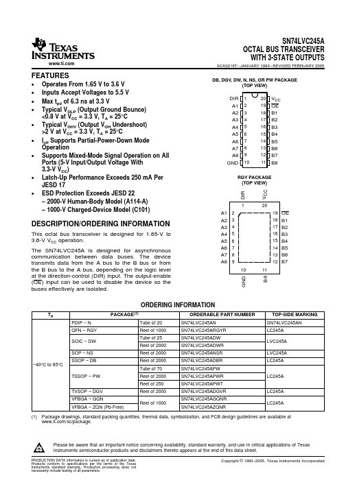
GQN OR ZQN PACKAGE (TOP VIEW)
1234
A B C D E
TERMINAL ASSIGNMENTS
1
2
3
4
A
A1
DIR
VCC
OE
B
A3
B2
A2
B1
C
A5
A4
B4
B3
D
A7
B6
A6
B5
E
GND
A8
B8
B7
FUNCTION TABLE
INPUTS
OE DIR
L
L
L
H
H
X
OPERATION
QFN – RGY
Reel of 1000
SN74LVC245ARGYR
SOIC – DW
Tube of 25 Reel of 2000
SN74LVC245ADW SN74LVC245ADWR
SOP – NS
Reel of 2000
SN74LVC245ANSR
SSOP – DB
Reel of 2000
Please be aware that an important notice concerning availability, standard warranty, and use in critical applications of Texas Instruments semiconductor products and disclaimers thereto appears at the end of this data sheet.
DIR 1 A1 2 A2 3 A3 4 A4 5 A5 6 A6 7 A7 8 A8 9 GND 10
- 1、下载文档前请自行甄别文档内容的完整性,平台不提供额外的编辑、内容补充、找答案等附加服务。
- 2、"仅部分预览"的文档,不可在线预览部分如存在完整性等问题,可反馈申请退款(可完整预览的文档不适用该条件!)。
- 3、如文档侵犯您的权益,请联系客服反馈,我们会尽快为您处理(人工客服工作时间:9:00-18:30)。
Am41DL32x8G
Data Sheet
July 2003 The following document specifies Spansion memory products that are now offered by both Advanced Micro Devices and Fujitsu. Although the document is marked with the name of the company that originally developed the specification, these products will be offered to customers of both AMD and Fujitsu.
P R E L I M I N A R Y
GENERAL DESCRIPTION Am29DL32xG Features
The Am29DL322G/323G/324G consists of 32 megabit, 3.0 volt-only flash memory devices, organized as 2,097,152 words of 16 bits each or 4,194,304 bytes of 8 bits each. Word mode data appears on DQ15–DQ0; byte mode data appears on DQ7–DQ0. The device is designed to be programmed in-system with the standard 3.0 volt VCC supply, and can also be programmed in standard EPROM programmers. The devices are available with access times of 70 and 85 ns. The device is offered in a 73-ball FBGA package. Standard control pins—chip enable (CE#f), write enable (WE#), and output enable (OE#)—control normal read and write operations, and avoid bus contention issues. The devices requires only a single 3.0 volt power supply for both read and write functions. Internally generated and regulated voltages are provided for the program and erase operations.
s Data# Polling and Toggle Bits
— Provides a software method of detecting the status of program or erase cycles
s Unlock Bypass Program command
— Reduces overall programming time when issuing multiple program command sequences
s Power supply voltage of 2.7 to 3.3 volt s High performance
— Access time as fast as 70 ns
SOFTWARE FEATURES
s Data Management Software (DMS)
— AMD-supplied software manages data programming and erasing, enabling EEPROM emulation — Eases sector erase limitations
Continuity of Specifications
There is no change to this datasheet as a result of offering the device as a Spansion product. Any changes that have been made are the result of normal datasheet improvement and are noted in the document revision summary, where supported. Future routine revisions will occur when appropriate, and changes will be noted in a revision summary.
s Power dissipation
— Operating: 30 mA maximum — Standby: 15 µA maximum
s Ultra low power consumption (typical values)
— 2 mA active read current at 1 MHz — 10 mA active read current at 5 MHz — 200 nA in standby or automatic sleep mode
Amendment +1 Issue Date September 5, 2002
元器件交易网
PRELIMINARY
Am41DL32x8G
Stacked Multi-Chip Package (MCP) Flash Memory and SRAM
32 Megabit (4 M x 8-Bit/2 M x 16-Bit) CMOS 3.0 Volt-only, Simultaneous Read/Write Flash Memory and 8 Mbit (1 M x 8-Bit/512 K x 16-Bit) Static RAM DISTINCTIVE CHARACTERISTICS MCP Features
s Secured Silicon (SecSi) Sector: Extra 256 Byte sector
— Factory locked and identifiable: 16 bytes available for secure, random factory Electronic Serial Number; verifiable as factory locked through autoselect function. — Customer lockable: Sector is one-time programmable. Once locked, data cannot be changed
Continuity of Ordering Part Numbers
AMD and Fujitsu continue to support existing part numbers beginning with “Am” and “MBM”. To order these products, please use only the Ordering Part Numbers listed in this document.
Publication# 25558 Rev: A Amendment/+1 Issue Date: September 5, 2002
Refer to AMD’s Website () for the latest information.
元器件交易网
s Operating Temperature
— –40°C to +85°C
Flash Memory Features
ARCHITECTURAL ADVANTAGES
s Simultaneous Read/Write operations
— Data can be continuously read from one bank while executing erase/program functions in other bank — Zero latency between read and write operations
HARDWARE FEATURES
s Any combination of sectors can be erased s Ready/Busy# output (RY/BY#)
— Hardware method for detecting program or erase cycle completion
For More Information
Please contact your local AMD or Fujitsu sales office for additional information about Spansion memory solutions.
Publication Number 25558 Revision A
s Top or bottom boot block s Manufactured on 0.17 µm process technology s Compatible with JEDEC standards
— Pinout and software compatible with single-power-supply flash standard
PERFORMANCE CHARACTERISTICS
s High performance
— Access time as fast as 70 ns — Program time: 4 µs/word typical utilizing Accelerate function