Q5手套箱履历Magotan20091030
2017年式AudiQ5规格配备表

Aluminium Rhombus 飾板 無邊框車內後視鏡(附自動防眩) 遮陽板附照明/化妝鏡 手動後門窗遮陽簾 室內照明套件 真皮/金屬遊艇式排檔桿頭 鋁合金門檻踏板 電動啟閉尾門 行李廂底板下方置物空間 行李廂分隔網 原廠工具組 急救包/三角警告標誌 安全配備 ABS 防鎖定煞車系統 EBD 電子煞車力分配系統 ASR 循跡防滑系統 ESC 行車動態穩定系統 HDC 陡坡緩降輔助系統 EDL 電子前後軸差速器鎖定功能 Audi hold assist 主動駐車輔助系統 + 斜坡起步輔助 系統 光感應自動啓閉頭尾燈 電子線傳式手煞車含緊急煞車功能 電子引擎禁制啟動裝置 駐車輔助系統(前後感知) 倒車攝影機 360 度全視角顯影 自動停車輔助系統 全車三點式安全帶 安全帶未繫警示裝置 雙前座 SRS 氣囊 雙前座 SRS 側氣囊 車側 SRS 頭部氣囊 電子式兒童安全鎖(後座車窗與車門) 後座兩側 ISOFIX 兒童安全座椅固定扣 胎壓監測警示系統 座椅配置 真皮/透氣皮質 跑車前座椅 雙前座電動椅 雙前座四向電動腰靠 雙前座頭枕高度可調 前座中央扶手附置杯架 後座 40/20/40 分離傾倒椅背 空調/音響/通訊系統 日照感應式三區獨立恆溫空調(含後座空調出風口) MMI navigation plus 多媒體系統 (8.3 吋顯示幕,含 DVD 播放器可讀 MP3/WMA/AAC 等格式光碟,具中 文聲控/輸入功能) 原廠中文導航系統 大型 5.1 吋 MMI 觸控手寫板 Audi 原廠音響系統(10 支高傳真喇叭) 雙 SDXC 讀卡機插槽及雙 USB 插槽 藍牙免持通訊裝置及音樂傳輸功能 Audi 智慧手機介面 註: 1.●為標準配備,-為選配或無此配備。 2.規格配備以實車為準,原廠保留設計變更之權利。 3.車高含車頂天線。 4.2017/05 更新,適用 17/17 年式。
09年奥迪q5变速器维修手册
拆卸和安装机械电子单元
拆卸 变速箱已安装。
当心! 变速箱有损坏危险。 当变速箱内部无 ATF 且双离合器变速箱机械电子单元 -J743取下时,发动机不允许起动。
提示 一般维修提示 → Kapitel。 对双离合器变速箱进行操作时的清洁规定 → Kapitel。 有关双离合器变速箱 0B5 的提示 → Kapitel。 – 将选档杆切换到“P”位置。 – 关闭点火开关并拔出点火钥匙。
Page 1 of 2 2015-9-10
拆卸和安装机械电子单元
– 安装 ATF 抽吸滤清器 → 修理 - 双离 合器变速箱; 修理组:34; 机械电子单 元;拆卸和安装机械电子单元。
– 安装 ATF 油底壳 → Kapitel。 – 加注变速箱油 → Kapitel。 更换双离合器变速箱机械电子单元 -
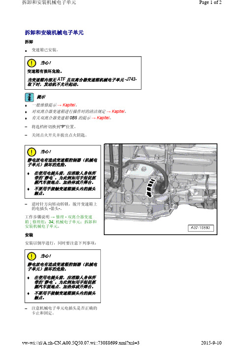
当心! 静电放电有造成变速箱控制器(机械电 子单元)损坏的危险。 在使用电插头前,应消除人身体所
带的“静电”。为此例如用手短促抓 握汽车接地点、加热体或升降台。 不要用手接触变速箱插头内的插头 触点。
– 逆时针方向转动转锁,脱开变速箱上 的电插头 -箭头-。
工作步骤说明 → 修理 - 双离合器变速 箱 ; 修理组:34; 机械电子单元;拆卸和 安装机械电子单元。 安装 安装以倒序进行,同时要注意下列事项:
J743- 后,必须通过汽车诊断测试仪执 行相应的“引导功能” → Kapitel。
Page 2 of 2
vw-wi://rl/A.zh-CN.A00.5Q50.07.wi::73088699.xml?xsl=3
2015-9-10
当心! 静电放电有造成变速箱控制器(机械电 子单元)损坏的危险。 在使用电插头前,应消除人身体所
09年奥迪q5变速器维修手册
拆卸和安装油底壳
拆卸
提示
♦ 一般维修提示 → Kapitel 。
♦ 对双离合器变速箱进行操作时的清洁规定 → Kapitel 。
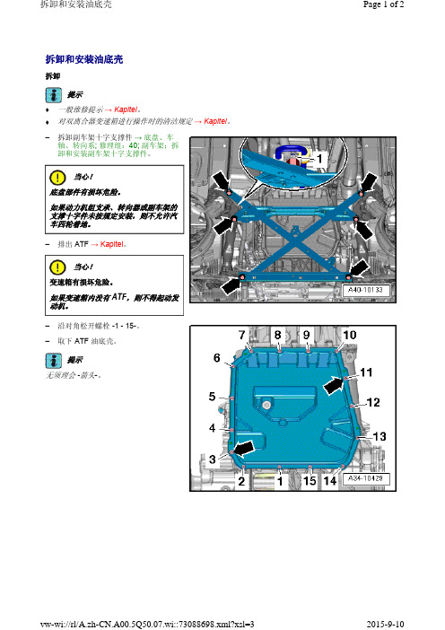
– 拆卸副车架十字支撑件 → 底盘、车轴、转向系; 修理组:40; 副车架;拆卸和安装副车架十字支撑件。
当心!底盘部件有损坏危险。
如果动力机组支承、转向器或副车架的支撑十字件未按规定安装,则不允许汽车四轮着地。
– 排出 ATF → Kapitel。
当心!
变速箱有损坏危险。
如果变速箱内没有 ATF ,则不得起动发动机。
– 沿对角松开螺栓 -1 - 15-。
– 取下 ATF
油底壳。
提示无须理会 -箭头-。
安装
安装以倒序进行,同时要注意下列事项:– 清洁密封面。
– 更新 ATF 油底壳螺栓和密封件。
– 将新的密封件 -2- 的凸块 -箭头- 装入 ATF 油底壳 -1-。
– 如果存在,将密封件用卡子 -3- 固定在 ATF
油底壳上。
提示卡子 -图中位置 3- 只作为装配辅助工具在生产中使用!
– 清洁 ATF 油底壳中的磁铁 -箭头-。
– 注意磁铁的平面处应紧贴在 ATF 油底壳上。
– 拧紧 ATF 油底壳的螺栓 → 修理 - 双离合器变速箱; 修理组:34; 机械电子单元; 装配一览 - 机械电子单元。
– 加注变速箱油 → Kapitel 。
2009 Audi Q5 拴车架(ECE)安装说明书

Installation instructionsAudi Q5 2009 ▶Towing bracket (ECE), for scope of delivery 8R0 092 157*Audi Genuine Accessories®Edition 01/2013ServiceService Department. Technical InformationContents1General notes . . . . . . . . . . . . . . . . . . . . . . . . . . . . . . . . . . . . . . . . . . . . . . . . . . . . . . . . . . . . . . . . . . . . . . . . . . . . . . . . . . . . . . . . . . . . . .12Notes on towing bracket Fitting and operation . . . . . . . . . . . . . . . . . . . . . . . . . . . . . . . . . . . . . . . . . . . . . . . . . . . . . . .23Parts allocation . . . . . . . . . . . . . . . . . . . . . . . . . . . . . . . . . . . . . . . . . . . . . . . . . . . . . . . . . . . . . . . . . . . . . . . . . . . . . . . . . . . . . . . . . . . .44Preparations . . . . . . . . . . . . . . . . . . . . . . . . . . . . . . . . . . . . . . . . . . . . . . . . . . . . . . . . . . . . . . . . . . . . . . . . . . . . . . . . . . . . . . . . . . . . . . . .64.1Assembly overview of luggage compartment floor . . . . . . . . . . . . . . . . . . . . . . . . . . . . . . . . . . . . . . . . . . . . . . . . . . . . . . .74.2Removing front luggage compartment floor . . . . . . . . . . . . . . . . . . . . . . . . . . . . . . . . . . . . . . . . . . . . . . . . . . . . . . . . . . . . . . .74.3Vehicles with support rails Removing support rails . . . . . . . . . . . . . . . . . . . . . . . . . . . . . . . . . . . . . . . . . . . . . . . . . . . . . . .84.4Vehicles with fixed fastening rings — Removing the fastening rings . . . . . . . . . . . . . . . . . . . . . . . . . . . . . . . . . . . .84.5Removing trim cover for door . . . . . . . . . . . . . . . . . . . . . . . . . . . . . . . . . . . . . . . . . . . . . . . . . . . . . . . . . . . . . . . . . . . . . . . . . . . . . .84.6Removing rear retainer . . . . . . . . . . . . . . . . . . . . . . . . . . . . . . . . . . . . . . . . . . . . . . . . . . . . . . . . . . . . . . . . . . . . . . . . . . . . . . . . . . . . .94.7Assembly overview of rear cross panel trim . . . . . . . . . . . . . . . . . . . . . . . . . . . . . . . . . . . . . . . . . . . . . . . . . . . . . . . . . . . . . .104.8Removing the rear cross panel trim . . . . . . . . . . . . . . . . . . . . . . . . . . . . . . . . . . . . . . . . . . . . . . . . . . . . . . . . . . . . . . . . . . . . . . .104.9Assembly overview of luggage compartment side trim . . . . . . . . . . . . . . . . . . . . . . . . . . . . . . . . . . . . . . . . . . . . . . . . . .114.10Removing the suit hanger . . . . . . . . . . . . . . . . . . . . . . . . . . . . . . . . . . . . . . . . . . . . . . . . . . . . . . . . . . . . . . . . . . . . . . . . . . . . . . . . . .124.11Removing the luggage compartment side trim . . . . . . . . . . . . . . . . . . . . . . . . . . . . . . . . . . . . . . . . . . . . . . . . . . . . . . . . . . .124.12Assembly overview of rear bumper cover . . . . . . . . . . . . . . . . . . . . . . . . . . . . . . . . . . . . . . . . . . . . . . . . . . . . . . . . . . . . . . . . .134.13Removing the rear bumper cover . . . . . . . . . . . . . . . . . . . . . . . . . . . . . . . . . . . . . . . . . . . . . . . . . . . . . . . . . . . . . . . . . . . . . . . . . .154.14Making an opening for connecting towing bracket to diffuser . . . . . . . . . . . . . . . . . . . . . . . . . . . . . . . . . . . . . . . . . . . .185Fitting the towing bracket . . . . . . . . . . . . . . . . . . . . . . . . . . . . . . . . . . . . . . . . . . . . . . . . . . . . . . . . . . . . . . . . . . . . . . . . . . . . . . . .195.1Assembly overview of towing bracket . . . . . . . . . . . . . . . . . . . . . . . . . . . . . . . . . . . . . . . . . . . . . . . . . . . . . . . . . . . . . . . . . . . . .195.2Fitting the towing bracket . . . . . . . . . . . . . . . . . . . . . . . . . . . . . . . . . . . . . . . . . . . . . . . . . . . . . . . . . . . . . . . . . . . . . . . . . . . . . . . . . . .205.3Other tightening torques . . . . . . . . . . . . . . . . . . . . . . . . . . . . . . . . . . . . . . . . . . . . . . . . . . . . . . . . . . . . . . . . . . . . . . . . . . . . . . . . . . . .246Concluding operations . . . . . . . . . . . . . . . . . . . . . . . . . . . . . . . . . . . . . . . . . . . . . . . . . . . . . . . . . . . . . . . . . . . . . . . . . . . . . . . . . . .25ServiceAll rights reserved.No reproduction without prior agreement from publisher.Copyright © 2012 Audi AG, IngolstadtPrinted in Germany1General notesPlease read and take note of these DANGER, WARNING, Cau-tion and Note descriptions before carrying out maintenance or repair work or fitting add-on parts.WARNING◆Text with this symbol contains information concerning your safety and how you can reduce the risk of serious and fatal injuries.◆Pay special attention to the WARNING symbol. Make sure that you read the relevant texts thoroughly. Caution◆Text with this symbol contains information on how to avoid vehicle damage.◆A Caution symbol indicates that failure to follow infor-mation could lead to damage to the vehicle (e.g. make sure that the ignition has been switched off before the vehicle battery is connected, otherwise the engine con-trol unit could be damaged).Note◆Text with this symbol contains additional useful information.◆A Note symbol also contains special and additional informa-tion on repair measures and associated information.Special tools are required for assembly. Improper installa-tion can cause damage to the vehicle or the add-on compo-nents.AUDI AG will not accept responsibility in the event of fail-ure to comply with these assembly instructions.Installation instructions - Audi Q5 2009 ▶Edition 01/20131 General notes12Notes on towing bracket Fitting and operationTowing vehicle Manufacturer:AUDI AG Model:Q5 2009 ►Type:8RMaximum trailer weight or trailer drawbar load in kg, as specified by the manufacturer for the above model: ⇒ vehi-cle registration certificate/Owner's Manual.Towing bracket:Technical data ORIS model code E446EU No.:e1* 94/20* 1777* xxDetails in the vehicle registration certificate are decisive.The towing bracket is intended for towing trailers fitted with a tow ball and for operating carriers suitable for mounting to the coupling ball.Nationally applicable regulations must be adhered to in EU and non-EU countries.Improper use is prohibited.Use is only permitted under favourable road conditions and must be adapted to road conditions.FittingInstallation instructions - Audi Q5 2009 ▶Edition 01/201322 Notes on towing bracket Fitting and operationCautionTowing mode places increased demands on the cooling system.◆Please consult a qualified workshop should modifica-tions to the cooling system be required. Further notes can be found in the “towing mode” guidebook.–Remove body cavity sealant (wax) or insulation material from the area around the contact surfaces of the towing bracket with the vehicle underseal.–In order to provide adequate corrosion protection to bare metal body parts, apply the following products with a brush.◆Single-component primer filler/surfacer LGF 008 001 42/A3◆Two-component vario filler/surfacer, grey LGF 786 004 A3◆Paint to match the vehicle colour◆Body cavity preserving agent D 330 KD2 A1OperationWARNINGVehicle handling is affected by the use of towing mode; in-creased driver awareness is required.●Carefully read the notes in the “Towing mode” ⇒ chap-ter of the vehicle Owner's Manual.The ball coupling must always be kept clean. A cover must be used.●If you are using trailer stabilisers, the coupling ball must be free from grease. Carefully read the notes in the rele-vant Owner's Manuals.The diameter of the ball coupling must be checked at regu-lar intervals.●For safety reasons, use of the towing bracket must be discontinued if the diameter reaches 49 mm at any point. If this situation occurs, contact a qualified work-shop.For safety reasons, you are advised to swivel the ball rodinwards when not in use. Note◆The towing bracket including all assembly parts weighs ap-prox. 30 kg.◆Please note that the kerb weight of your vehicle will increase by this amount once the towing bracket is fitted.◆Please make sure that you do not exceed the gross vehicle weight rating for your vehicle.NoteUse the towing bracket when towing.Installation instructions - Audi Q5 2009 ▶Edition 01/20132 Notes on towing bracket Fitting and operation33Parts allocationParts set 8R0 092 155.Installation instructions - Audi Q5 2009 ▶Edition 01/201343 Parts allocation1 - Towing bracket 2 - Coupling release mechanism 3 - Actuating lever with securing clip 4 - Bolt, M10x105 10.9(4x)5 - Bolt (2x)6 - Pop rivet nut (2x)Series production models–Select a diffuser with towing bracket opening and trim panel from the electronic parts catalogue (ETKA) ⇒ ETKA and re-place, or cut out diffuser using workshop tools ⇒ P age 18.Vehicles with S line packageThese vehicles are equipped with towing bracket opening and trim panel on the diffuser.Vehicles with offroad styling package–Select impact guard and trim panel with fastening equipment for towing mode from ETKA ⇒ ETKA and replace ⇒ P age 18.Installation instructions - Audi Q5 2009 ▶Edition 01/20133 Parts allocation54PreparationsSpecial tools and workshop equipment required ◆Removal lever -80 - 200-◆Removal wedge -3409-Installation instructions - Audi Q5 2009 ▶Edition 01/201364 Preparations4.1Assembly overview of luggage compartment floor1 - Screw q 4 x q 60 Nm2 - Trim cover for door q Removal ⇒ P age 83 - Support railq Equipment variant q Removal ⇒ P age 8q Alternatively, fixed fastening rings —removal ⇒ P age 84 - Screw q 6 x q 4 Nm5 - Rear boot flooring 6 - Front boot flooring q Removal ⇒ P age 77 - Screw q 4 x q 60 Nm 8 - Front bracket 9 - Rear bracket q Removal ⇒ P age 94.2Removing front luggage compartment floor–Fold the rear seat backrests forwards.–Remove the rear luggage compartment floor.–Lift up front luggage compartment floor -1- (-arrow A-) andremove it to the rear (-arrows B-).Installation instructions - Audi Q5 2009 ▶Edition 01/20134 Preparations74.3Vehicles with support rails Removing support railsNoteInstallation and removal are identical on both the right and left.–Remove bolts -1, 2- and remove support rails -3-.Tightening torque ⇒ P age 7.4.4Vehicles with fixed fastening rings —Removing the fastening ringsNoteInstallation and removal are identical on both the right and left.–Fold the fastening rings -1- upwards.–Remove the bolts -arrows- and the fastening ring attach-ments -2-.Tightening torque ⇒ P age 244.5Removing trim cover for doorNoteInstallation and removal are identical on both the right and left.–Remove dirt tray, if there is one.Installation instructions - Audi Q5 2009 ▶Edition 01/201384 Preparations–Swivel the front trim cover for door -1- backwards -arrow-, detach from the rear cross panel trim and remove.4.6Removing rear retainerNoteInstallation and removal are identical on both the right and left.–Remove bolts -1, 2- and rear holder -3-.Tightening torque ⇒ P age 7.4.7Assembly overview of rear cross panel trim1 - Centring pin2 - Fastenersq4 xq Insert into the trimq replace if damagedor deformed3 - Rear cross panel trimq Removal⇒ P age 104.8Removing the rear cross panel trim–Using the removal lever -80 - 200-, unclip the rear cross panel trim -1- vertically using an upwards motion -arrows-.–Carefully remove the rear cross panel trim by pulling up-wards and disconnect the electrical connector for rear lidclosed senders -G525-/ -G526-.Note◆Installation is carried out in reverse order. Please note thefollowing points:◆If fasteners for the panelling remained in holes in the bodyused for attachment, remove the fasteners and insert intothe panelling for use when re-installing.◆Check the fasteners for damage or deformation and replaceas necessary.◆Press on the rear cross panel trim until the unit audibly en-gages and place the rubber lip of the seal for the rear lidover the rear cross panel trim.4.9Assembly overview of luggage compartment side trim1 - Luggage compart-ment side trimq Removal⇒ P age 122 - Fastenersq3 xq Insert into the trimq replace if damagedor deformed3 - Luggage compart-ment light4 - Screwq3 Nm5 - suit hangerq Removal⇒ P age 126 - Rear backrest release7 - Coverq for luggage com-partment side trim4.10Removing the suit hangerNoteInstallation and removal are identical on both the right and left.–Using the removal lever -80 - 200-, pull up the rear suit hanger -1- until it lifts away slightly from the side trim -arrow A- and pull it backwards away from the side trim -arrow B-.NoteWhen installing the suit hanger, insert it into the side trim and push it in until you hear it click into place.4.11Removing the luggage compartmentside trimNoteInstallation and removal are identical on both the right and left.–Remove cover for luggage compartment side trim.–Unscrew the screw -2-.–Using the removal lever -80 - 200-, prise the luggage com-partment side trim -1- away from the body -arrows A-.–Using the removal wedge -3409-, unclip and remove the lug-gage compartment side trim near the D pillar trim -arrow B-and rear sill panel trim -arrow C-.–Position side trim with attached wires in luggage compart-ment.Note◆Installation is carried out in reverse order. Please note thefollowing points:◆If fasteners for the trims remained in holes in the body usedfor attachment, remove the fasteners and insert into thetrims for use when re-installing.◆Check the fasteners for damage or deformation and replaceas necessary.◆Hold luggage compartment side trim in position and pressuntil you hear it click into place.◆Place the rubber lip of the seal for the rear lid over the lug-gage compartment side trim.4.12Assembly overview of rear bumper cov-erWARNING◆The following information must be observed when work-ing with the lane change assistant (Audi side assist):◆If the rear bumper is removed and then reinstalled or ifany modifications are made to the rear bumper, the lane change assistant (Audi side assist) must be recalibrated⇒ R ep. gr. 96.1 - Rear bumper cover q Removal⇒ P age 152 - Screwq1.5 Nm3 - Guide partq Removal4 - Screwq1.5 Nm5 - Clip6 - Impact barq Impact bars withtwo longitudinal fit-ting parts are nolonger required.7 - Screwq1.5 Nm8 - Spoilerq Equipment variant 9 - Trim panel10 - Clipq Unclip bumper onboth sides beforepulling back to re-move.Tail light cluster screw3 - 2.5 NmBumper cover studs3 - 4 NmReceiver for radio controlled clockArrows - 2.5 Nm4.13Removing the rear bumper cover–Prise off the cover -2-, undo screw -3- and disconnect elec-trical connector to tail light cluster -1-.–If one is fitted, disconnect the electrical connector -1- from the parking aid control unit -J446-.–Uncover electrical wiring harness from control unit retainer -arrow- and remove cable tie -2-.–Push grommet -3- through towards the rear.–Unscrew nuts -3- from cover studs -1-.–Undo screws -1- at the cover (top) and spoiler (bottom).–Unscrew the screws -1- on the bottom part of the bumper cover.–Unclip cover from the rear cross panel at the left and right ⇒ I tem 10 on page 14.–Unclip cover from the guide parts at the left and right and move to the side.–Remove cover from the vehicle by pulling up to the rear and dispose of it.NoteAfter fitting the towing bracket, the impact bar is no longer re-quired.Vehicles with radio controlled clock–Unscrew the receiver for radio controlled clock -J489-.–Remove the impact bar from the body.Notes on installation–When installing, the side guide part -2- must be fully engag-ed in the bumper cover -1-.–If one is fitted, connect the electrical connector to the parking aid control unit -J446- ⇒ R ep. gr. 94.–Install tail light cluster.Tightening torques ⇒ “Assembly overview of rear bumper cover” on page 134.14Making an opening for connecting tow-ing bracket to diffuser4.14.1 Cutting an opening for connecting towingbracket to diffuser if required–Where indicated -Arrows- on the diffuser, cut out the outer section using workshop tools.–Deburr the cut surfaces.4.14.2 Or replacing the spoiler1 - Spoiler–Unscrew screws -3-.–To disassemble, un-fasten catches -ar-rows- step by stepand remove frombumper cover.–When installing, theclips -arrows- mustbe fully engaged inthe bumper cover.2 - Bumper coverq Installed3 - Screwq1.5 Nm5Fitting the towing bracket 5.1Assembly overview of towing bracket1 - Towing bracket withcross memberq Installation ⇒ P age 202 - Bowden cableq When installing,push grommet prop-erly into rear crosspanel.3 - Left-hand bracket4 - Screwq 60 Nm5 - Right-hand bracketInstallation instructions - Audi Q5 2009 ▶Edition 01/20135 Fitting the towing bracket 19Retainer for manual operation1 - Retainer for manualoperation2 - Pop rivet nut3 - “D pillar”4 - Screwq 8 Nm5 - Actuating lever–When installing, theretaining clip mustengage in the ac-tuating lever.–To disassemble, re-move retaining clip.6 - Retaining clip7 - Bowden cableq When installing,push grommet prop-erly into rear crosspanel.8 - Grommet5.2Fitting the towing bracketSpecial tools and workshop equipment required◆Pop rivet nut pliers -V.A.G 1765B-Installation instructions - Audi Q5 2009 ▶Edition 01/201320 5 Fitting the towing bracket–Remove cover -arrow-.–Pull out catch cable -1- from behind K box through opening -arrow-.–Insert cable grommet.–Insert pop rivet nuts from the assembly set into the back panel -1- and fasten using pop rivet nut pliers-V.A.G 1765B-.–Attach mechanism to back panel -arrows- and push down as far as it will go.–Screw mechanism into pop rivet nuts -1- using screws provi-ded.–Insert rubber grommet on cable into bore hole.Installation instructions - Audi Q5 2009 ▶Edition 01/20135 Fitting the towing bracket21–Push actuating lever -1- onto shaft of mechanism. The splines -2- are irregular and can only be fitted in one posi-tion.–Close securing clip -3-.–Remove rubber grommet from the back panel in the centre of the vehicle.–Fit towing bracket and position it approx. 10 cm away from the back panel.–Feed the wiring harness through the hole in the back panel -arrow 1- and insert cable grommet.–Push the fastening element for the wiring harness onto the welding studs -arrow 2-.–Bring the towing bracket into the installation position.–Insert and manually tighten all securing bolts with supports for luggage compartment floor.–Tighten securing bolts.Vehicles with radio controlled clock:Installation instructions - Audi Q5 2009 ▶Edition 01/201322 5 Fitting the towing bracket–Position and screw in the receiver for radio controlled clock -J489- on the towing bracket retainer -arrow-.All vehicles:–Attach cable for folding function to boot:1 - Remove transport lock2 - Open cover3 - Attach nipples4 - Attach counterhold tool5 - Close cover you will hear it click into placeWhen fitting the bumper cover, there must be an opening for the towing bracket. The following modifications must be made, de-pending on vehicle features:Series production vehicles:–Remove the diffuser from the bumper cover.–Fit the diffuser with opening for the towing bracket to the bumper cover.Vehicles with S line packageThese vehicles are equipped with a cover for the opening in the diffuser that is necessary to fit the towing bracket.Vehicles with offroad styling package–Remove the diffuser/protector from the bumper cover.–Fit the diffuser/protector with opening for the towing bracket to the bumper cover.All vehicles–Fit the bumper cover.–Fit the electrical installation kit ⇒ Installation instructions for electrical installation kit.–Carry out a functional check. Swivel the towing bracket out and back in again ⇒ Vehicle Owner's Manual.–Complete vehicle.Installation instructions - Audi Q5 2009 ▶Edition 01/20135 Fitting the towing bracket23–Fit the “Towing with towing bracket” sticker to the actuating lever used for pulling out the towing bracket -arrow-.5.3Other tightening torquesFastening ringsArrows - 4 NmComponent NmScrews M10x105 (towing bracket on body)60Receiver for radio controlled clock -J489-5Installation instructions - Audi Q5 2009 ▶Edition 01/201324 5 Fitting the towing bracket6Concluding operations–On vehicles with lane change assist (Audi side assist), this must be recalibrated ⇒ R ep. gr. 96. WARNING◆If the rear bumper is removed and then reinstalled or if any modifications are made to the rear bumper, the lane change assistant (Audi side assist) must be recalibrated ⇒ R ep. gr. 96.–Keep these assembly instructions with the vehicle docu-ments.NoteKeep these assembly instructions with the vehicle documents so that they can be presented to authorised persons upon re-quest.Installation instructions - Audi Q5 2009 ▶Edition 01/20136 Concluding operations 25。
09年奥迪q5变速器维修手册
装置; 修理组:27; 蓄电池;断开/连接 蓄电池。 – 用废油盛接和抽吸装置 -V.A.G 1782从储液罐内抽出助力转向系统液压 油。
vw-wi://rl/A.zh-CN.A00.5Q50.07.wi::73088726.xml?xsl=3
– 旋出螺栓 -1-。
vw-wi://rl/A.zh-CN.A00.5Q50.07.wi::73088726.xml?xsl=3
2015-9-10
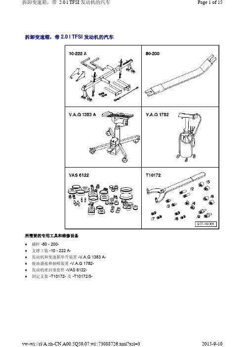
拆卸变速箱,带 2.0 l TFSI 发动机的汽车
当心! 前排气管内的分离元件有损坏危险。 排气预导管内分离元件弯折不得超过 10°。 – 松开螺栓连接 -箭头- 并将夹紧套向后
拆卸变速箱,带 2.0 l TFSI 发动机的汽车
– 如图所示,将支撑工装 -10 - 222 A和适配接头 -10 - 222 A /3- 放到左侧 和右侧减震支柱罩上。
– 将丝杆 -10 - 222 A /11- 挂到发动机吊 耳上。
– 用丝杆略微预紧发动机。
Page 6 of 15
– 拆卸左侧和右侧前车轮。 – 拆下轮罩内的左右摆动半轴盖板 -1-。
vw-wi://rl/A.zh-CN.A00.5Q50.07.wi::73088726.xml?xsl=3
2015-9-10
拆卸变速箱,带 2.0 l TFSI 发动机的汽车
固定支架 -T10355-
Page 2 of 15
变速箱定位架 -T40173-
vw-wi://rl/A.zh-CN.A00.5Q50.07.wi::73088726.xml?xsl=3
手套箱Mikrouna使用说明书
目录一、常用操作 (2)1、开机 (2)2、关机 (2)3、物品放入手套箱 (2)4、物品拿出手套箱 (3)5、清洗 (3)6、再生 (3)7、水探头清洗(仅限于可清洗的探头) (4)二、日常维护 (4)三、常见故障及解决办法 (5)一、常用操作1、开机1)打开主电源开关(红色)2)打开工作气减压阀(主阀门开到最大、副阀门开到0.4~0.6Mpa)3)启动循环(循环为24小时开启)。
4)启动分析仪(氧指标在水指标降到200ppm以下时开始显示)5)启动冷却水循环机(如果有的话)6)将箱体压力设置为:+1~+6mbar2、关机1)关闭水氧分析仪2)关闭循环3)关闭真空泵4)关闭冷却水循环机5)关闭工作气减压阀主阀6)关闭主电源开关3、物品放入手套箱1)给过渡舱补气、补气结束后关闭2)打开外舱门3)把物品放入舱内4)关闭外舱门5)抽气、补气各三次(液晶屏、密闭瓶子等不能抽太大负压的,可酌情减少抽气时间,增加抽气次数)6)打开内舱门7)取出物品8)关闭内舱门并随手抽一点负压PS:禁止将吸水性的物品如抹布、纸巾等直接放入,放入前先烘干!禁止在负压下试图打开内外舱门!禁止操作手套时手上带有戒指、手表等可破坏手套的物件。
(最好手套内外再各加一副手套,总三副手套)!4、物品拿出手套箱1)给过渡舱补气、补气结束后关闭2)打开内舱门(注意:打开前先确保舱内气氛为纯净,无法确定,需先抽气、补齐三次,使其纯净)3)把物品放入舱内4)关闭内舱门5)打开外舱门6)取出物品7)关闭外舱门并随手抽一点负压5、清洗1)定义:用工作气体置换箱内的气体,箱内气体从手套箱顶上的清洗阀排出2)步骤:①确保工作气充足;②关闭循环;③开启真空泵④开启清洗3)使用:①首次调试;②长时间未启用;③误操作,使得空气进入④清除箱内有机溶剂、酸碱溶剂等对手套箱有害的物质(有机溶剂等含量过高会影响氧探头和循环系统正常工作)6、再生1)再生气:氢气和惰性气体的混合气(氢气占5%-10%)2)再生气压力:0.06Mpa~0.08Mpa,小于0.1Mpa3)数量:40L的气瓶不小于10Mpa4)过程:3小时加热+3小时通气+18小时冷却及抽真空5)步骤:①连接再生气(连接后检查管路是否漏气:连接好后把减压阀主阀开到最大,把副表开到0.1Mpa,关掉主阀,等待15分钟,如果副表压力保持0.1Mpa不变,说明没有漏气)②将减压阀副表压力设置为0.1Mpa(通气时压力约为0.06-0.08MPa)③关闭循环和分析仪④打开真空泵⑤启动再生⑥24小时后再生自动结束6)注意:再生过程(尤其前6个小时)切勿断电断气!有些减压阀不准,需适当调节压力以保证3小时持续通气!7、水探头清洗(仅限于可清洗的探头)1)若水探头长时间不清洗,表面会附着一些脏东西,影响探测2)步骤:①关闭循环和分析仪②将工作压力设置为+5至+8mbar③拆下水探头,迅速用盲板盲住出气口④拧下探头前端的金属保护罩,用去离子水清洗,再用无尘纸擦干,再滴3~5滴清洗液清洗,再用无尘纸擦干⑤装回原处,打开循环,3分钟后打开分析仪,待半小时后可恢复正常水平二、日常维护1)操作手套箱后及时填写使用记录,包括“使用人、水氧值、做何操作”。
09年奥迪q5变速器维修手册
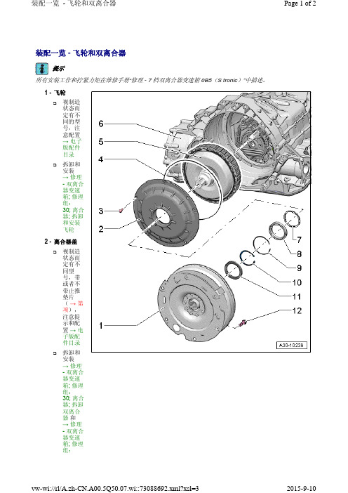
11 - 轴密封环 用于驱动轴 更换 → 修理 - 双离合器变速箱; 修理组:35; 驱动轴; 更换驱动轴密封环
12 - 螺栓 拧紧力矩参见维修手册 “修理 - 7 档双离合器变速箱 0B5(S tronic)”: → 修理 - 双离合器变速 箱; 修理组:30; 离合器;装配一览 - 飞轮和双离合器
2015-9-10
装配一览 - 飞轮和双离合器
Page 2 of 2
30; 离合 器; 安装 双离合 器
3 - 螺栓 拧紧力矩和拧紧顺序 → 修理 - 双离合器变速箱; 修理组:30; 离合器; 装配一览 视制造状态而定有不同的型号,注意配置 → 电子版配件目录 拆卸 → 修理 - 双离合器变速箱; 修理组:30; 离合器; 拆卸双离合器 安装 → 修理 - 双离合器变速箱; 修理组:30; 离合器; 安装双离合器
2 - 离合器盖
视制造 状态而 定有不 同型 号,带 或者不 带止推 垫片 (→第 项), 注意提 示和配 置→电 子版配 件目录
拆卸和 安装 → 修理 - 双离合 器变速 箱; 修理 组: 30; 离合 器; 拆卸 双离合 器和 → 修理 - 双离合 器变速 箱; 修理 组:
vw-wi://rl/A.zh-CN.A00.5Q50.07.wi::73088692.xml?xsl=3
装配一览 - 飞轮和双离合器
Page 1 of 2
装配一览 - 飞轮和双离合器
提示
所有安装工作和拧紧力矩在维修手册“修理 - 7 档双离合器变速箱 0B5(S tronic)”中描述。
1 - 飞轮
视制造 状态而 定有不 同的型 号,注 意配置 → 电子 版配件 目录
09年奥迪q5变速器维修手册

9 - 换档操纵机构的功能单元 只能整个更换 → Kapitel „拆卸和安装换档操纵机构“
10 - 选档杆锁电磁铁 -N110 → Kapitel „拆卸和安装换档杆锁电磁铁 -N110-“
装配一览 - 换档操纵机构
Page 2 of 2
拆卸和安装 → Kapitel „拆卸和安装选档杆手柄“
5 - 选档杆位置显示单元 -Y26 → Kapitel „拆卸和安装选档杆位置显示单元 -Y26-“
6 - 螺母 用于将换档操纵机构固定在车身上 4件 10 Nm
7 ห้องสมุดไป่ตู้ 密封件
3 - 选档杆密封 套
→ Kapitel „装配一览 - 选档杆 手柄“
→ Kapitel „断开选档 杆手柄的 选档杆密 封套,截 至 2012 年款的车 辆“
4 - 卡圈
vw-wi://rl/A.zh-CN.A00.5Q50.07.wi::73088701.xml?xsl=3
2015-9-10
不同的 型号、 配置 → 电子 版配件 目录
→ Kapitel „装配一览 - 选档杆 手柄“
→ Kapitel „拆卸和安 装选档杆 手柄“
2 - 装饰环
→ Kapitel „装配一览 - 选档杆 手柄“
拆卸和安 装 → Kapitel „断开选档 杆手柄的 选档杆密 封套,截 至 2012 年款的车 辆“
装配一览 - 换档操纵机构
Page 1 of 2
装配一览 - 换档操纵机构
注意!
在发动机运转时无意中挂入行驶档会带来受伤和事故危险。
- 1、下载文档前请自行甄别文档内容的完整性,平台不提供额外的编辑、内容补充、找答案等附加服务。
- 2、"仅部分预览"的文档,不可在线预览部分如存在完整性等问题,可反馈申请退款(可完整预览的文档不适用该条件!)。
- 3、如文档侵犯您的权益,请联系客服反馈,我们会尽快为您处理(人工客服工作时间:9:00-18:30)。
2.分析 Analysis:
1. 2. 3. 导套后卡位筋稍短. Guide sleeve behind the niche that some of the short ribs 锁扣本体滑道中间处偏窄. Lock the middle of some narrow-body slide 模具动静模配合不严密. Mold does not close with the dynamic and static modulus
Magotan 01S
日期
2009.10.30
手套箱/ Glovebox锦州希尔达/JINZHOU SEALCOAT
Magotan Glovebox 问题改进 (3CD 857 097) Improvement of open issue
1.问题描述Issues:
7. 右侧支架导套松动.The right bracket guide sleeve loose 8. 锁扣与底座配合滑道干涉. To interfere with the slide lock with the base 9. 扣手支架飞边过大,影响功能. Hand-clasping bracket fin is too large
Magotan 01S
日期
2009.10.30
手套箱/ Glovebox锦州希尔达/JINZHOU SEALCOAT
Magotan Glovebox 问题改进 (3CD 857 097) Improvement of open issue
1.问题描述Issues:
4. 连杆粗糙,飞边过大,影响开启功能 Rod is rough and the edge is too large
调整方向
调整方 上边缝 向 隙大
2.分析 Analysis:
CKD件有模具优化。 The CKD part have tooling modification.
下边缝 隙小
3.措施: Action:
3. 按CKD更改产品,加大隔板定位柱尺寸,消除定位柱与定位孔的间隙。Acc.to CKD,change
3.措施: Action:
4.修模严配模具 repair the Mold; 5. 按数据修改模具 Modify the tool In accordance with the 3D data. 6. 按数据修改模具 Modify the tool In accordance with the 3D data.
3.措施: Action:
10.辅助浇口位置参照样件下移.Auxiliary gate location reference Sample Down 11.按数据(2009.6.10)修改模具 Modify the tool In accordance with the 3D data(2008.6.10). 12.调整注塑工艺.Adjust the injection molding process
1. 03S手套箱左上角与仪表板面差过大,而且与仪表板间隙偏大。1.The upper left corner of 03S Glove box and IP have a poor surface ,The gap between the left corner and IP is too large. 2. 左右两侧铰链变形严重,与外框干涉,外盖开启后无法下落。The hingearm have too much deformation, that makes the lid can not fall down freely.
Magotan 01S
日期
2009.10.30
手套箱/ Glovebox锦州希尔达/JINZHOU SEALCOAT
Magotan
日期
手套箱/ Glovebox锦州希尔达/JINZHOU SEALCOAT
AUDI X88 Glovebox 问题改进 (8R1 857 035D) Improvement of open issue 1.问题描述Issues:
product location column to eliminate the gap between the positioning holes and the positioning
column. 4. 测量限位尺寸,按照CKD修改方法并根据测量结果修改手柄座限位尺寸。消除定位松动问 题.Measurement the limit size,modify the size by the results.
调整方向
2.分析 Analysis:
内盖板两侧轴孔不同心
different.
Cover both sides of the shaft hole in the heart of
两侧孔 不同心
3.措施: Action:
1.更换内盖板形成孔的模具销子,使两侧轴孔同心.Replacement the pin of tool. 2.调整焊接夹具,使盖板左上部抬高0.5mm. Adjust welding jig to elevate the upper left corner of Glove box 0.5mm.
日期
2009
手套箱/ Glovebox锦州希尔达/JINZHOU SEALCOAT
连杆底座
箱体减震钉
左右连杆
手套箱箱体
连杆弹簧 箱体笔架1 箱体笔架2 连杆导套 锁扣底座 连杆减震钉 锁扣本体 扣手支架 锁扣弹簧片 减震钉 滑道锁止 内六角螺钉 扣手弹簧 扣手本体 高配CD盒 高配阻尼器 低配储物盒 弹簧减震钉 拉带 轴销 阻尼器 卡式螺母 支架 连杆毛毡 盖板
location of narrow, open interference.
2.分析 Analysis:
1.未按照数据加工. Did not follow the Data Processing 2.模具加工尺寸不足. The tool finish size is insufficient; 3.模具加工尺寸不足. The tool finish size is insufficient;
Magotan
日期
手套箱/ Glovebox锦州希尔达/JINZHOU SEALCOAT
Magotan
日期
手套箱/ Glovebox锦州希尔达/JINZHOU SEALCOAT
Magotan
日期
手套箱/ Glovebox锦州希尔达/JINZHOU SEALCOAT
Magotan Glovebox 问题改进 (3CD 857 097) Improvement of open issue
Magotan 01S
日期
2009.10.30
手套箱/ Glovebox锦州希尔达/JINZHOU SEALCOAT
Magotan Glovebox 问题改进 (3CD 857 097) Improvement of open issue
1.问题描述Issues:
10.ቤተ መጻሕፍቲ ባይዱ安装堵盖处表面缺陷严重. Install blocking cap at surface defects of serious
4.重要事项 Attention:
05S手套箱通过一汽大众的疲劳试验。05S pass the FAW-VW dauerlauf test.
3.措施: Action:
1.按数据(2009.6.10)修改模具 Modify the tool In accordance with the 3D data(2009.6.10). 2.按数据(2009.6.10)修改模具 Modify the tool In accordance with the 3D data(2009.6.10). 3.按数据(2008.3.12)修改模具 Modify the tool In accordance with the 3D data(2009.6.10).
连杆飞边严 重,影响开 启
5. 连杆配合过紧. With the tight link 6. 导套高度与数据不符(数据日期2009.6.10). Guide height does not match with 3D data (2009.6.10)
2.分析 Analysis:
4. 模具动静模配合不严密. Mold does not close with the dynamic and static modulus ; 5.模具加工尺寸不足. The tool finish size is insufficient; 6.未按照数据加工. Did not follow the Data Processing
调整方向
2.分析 Analysis:
外板下部与内板焊接在Y向有偏移,如右图。 In the Y direction, below part of the outer board is deviate to left side.
向左调0.3mm
3.措施 Action:
调整焊接夹具,使外盖板向左偏移0.3mm. Adjust welding tool
手套箱/ Glovebox锦州希尔达/JINZHOU SEALCOAT
Magotan Glovebox history record
迈腾手套箱历史记录
3CD.857.097 /A
图纸日期/Drawings date:
2D : 2007.12.07
3D : 2009.06.10
版本号为
版本号为
Magotan
1.问题描述Issues:
1. 轴孔比3D数据(数据日期2009.6.10)尺寸大 Limit tendons is inconsistent with 3D data (2009.6.10) 2. 弹簧减震钉孔偏小,安装后开裂.Spring damping nail holes too small, installation crack 3. 箱体配合处两侧位置偏窄,开启干涉 . At both sides of the box with the