MAX352ESE+中文资料
MAX3490EESA+中文资料
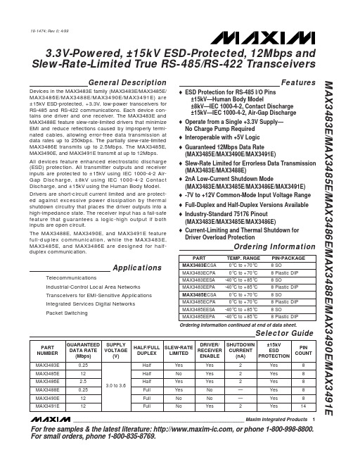
General DescriptionDevices in the MAX3483E family (MAX3483E/MAX3485E/MAX3486E/MAX3488E/MAX3490E/MAX3491E) are ±15kV ESD-protected, +3.3V, low-power transceivers for RS-485 and RS-422 communications. Each device con-tains one driver and one receiver. The MAX3483E and MAX3488E feature slew-rate-limited drivers that minimize EMI and reduce reflections caused by improperly termi-nated cables, allowing error-free data transmission at data rates up to 250kbps. The partially slew-rate-limited MAX3486E transmits up to 2.5Mbps. The MAX3485E,MAX3490E, and MAX3491E transmit at up to 12Mbps.All devices feature enhanced electrostatic discharge (ESD) protection. All transmitter outputs and receiver inputs are protected to ±15kV using IEC 1000-4-2 Air-Gap Discharge, ±8kV using IEC 1000-4-2 Contact Discharge, and ±15kV using the Human Body Model.Drivers are short-circuit current limited and are protect-ed against excessive power dissipation by thermal shutdown circuitry that places the driver outputs into a high-impedance state. The receiver input has a fail-safe feature that guarantees a logic-high output if both inputs are open circuit.The MAX3488E, MAX3490E, and MAX3491E feature full-duplex communication, while the MAX3483E,MAX3485E, and MAX3486E are designed for half-duplex communication.ApplicationsTelecommunicationsIndustrial-Control Local Area Networks Transceivers for EMI-Sensitive Applications Integrated Services Digital Networks Packet SwitchingFeatureso ESD Protection for RS-485 I/O Pins±15kV—Human Body Model±8kV—IEC 1000-4-2, Contact Discharge ±15kV—IEC 1000-4-2, Air-Gap Discharge o Operate from a Single +3.3V Supply—No Charge Pump Required o Interoperable with +5V Logic o Guaranteed 12Mbps Data Rate (MAX3485E/MAX3490E/MAX3491E)o Slew-Rate Limited for Errorless Data Transmission (MAX3483E/MAX3488E) o 2nA Low-Current Shutdown Mode(MAX3483E/MAX3485E/MAX3486E/MAX3491E)o -7V to +12V Common-Mode Input Voltage Range o Full-Duplex and Half-Duplex Versions Available o Industry-Standard 75176 Pinout (MAX3483E/MAX3485E/MAX3486E)o Current-Limiting and Thermal Shutdown for Driver Overload ProtectionMAX3483E/MAX3485E/MAX3486E/MAX3488E/MAX3490E/MAX3491E3.3V-Powered, ±15kV ESD-Protected, 12Mbps and Slew-Rate-Limited T rue RS-485/RS-422 T ransceivers________________________________________________________________Maxim Integrated Products119-1474; Rev 0; 4/99Selector GuideOrdering InformationOrdering Information continued at end of data sheet.For free samples & the latest literature: , or phone 1-800-998-8800.For small orders, phone 1-800-835-8769.M A X 3483E /M A X 3485E /M A X 3486E /M A X 3488E /M A X 3490E /M A X 3491E3.3V-Powered, ±15kV ESD-Protected, 12Mbps and Slew-Rate-Limited T rue RS-485/RS-422 T ransceiversABSOLUTE MAXIMUM RATINGSDC ELECTRICAL CHARACTERISTICS(V = +3.3V ±0.3V, T = T to T , unless otherwise noted. Typical values are at T = +25°C.)Stresses beyond those listed under “Absolute Maximum Ratings” may cause permanent damage to the device. These are stress ratings only, and functional operation of the device at these or any other conditions beyond those indicated in the operational sections of the specifications is not implied. Exposure to absolute maximum rating conditions for extended periods may affect device reliability.Supply Voltage (V CC ).............................................................+7V Control Input Voltage (RE , DE).................................-0.3V to +7V Driver Input Voltage (DI)...........................................-0.3V to +7V Driver Output Voltage (A, B, Y, Z).......................-7.5V to +12.5V Receiver Input Voltage (A, B)..............................-7.5V to +12.5V Receiver Output Voltage (RO)....................-0.3V to (V CC + 0.3V)Continuous Power Dissipation (T A = +70°C)8-Pin SO (derate 5.88mW/°C above +70°C)..................471mW 8-Pin Plastic DIP (derate 9.09mW/°C above +70°C).....727mW14-Pin SO (derate 8.33mW/°C above +70°C)................667mW 14-Pin Plastic DIP (derate 10mW/°C above +70°C)......800mW Operating Temperature RangesMAX34_ _ EC_ _...................................................0°C to +70°C MAX34_ _ EE_ _.................................................-40°C to +85°C Storage Temperature Range.............................-65°C to +150°C Lead Temperature (soldering, 10sec).............................+300°CMAX3483E/MAX3485E/MAX3486E/MAX3488E/MAX3490E/MAX3491E3.3V-Powered, ±15kV ESD-Protected, 12Mbps and Slew-Rate-Limited T rue RS-485/RS-422 T ransceiversDC ELECTRICAL CHARACTERISTICS (continued)(V CC = +3.3V ±0.3V, T A = T MIN to T MAX , unless otherwise noted. Typical values are at T A = +25°C.)DRIVER SWITCHING CHARACTERISTICS—MAX3485E/MAX3490E/MAX3491E(V = +3.3V, T = +25°C.)DRIVER SWITCHING CHARACTERISTICS—MAX3486E(V = +3.3V, T = +25°C.)*MAX3488E and MAX3491E will be compliant to ±8kV per IEC 1000-4-2 Contact Discharge by September 1999.M A X 3483E /M A X 3485E /M A X 3486E /M A X 3488E /M A X 3490E /M A X 3491E3.3V-Powered, ±15kV ESD-Protected, 12Mbps and Slew-Rate-Limited T rue RS-485/RS-422 T ransceivers4_______________________________________________________________________________________DRIVER SWITCHING CHARACTERISTICS—MAX3483E/MAX3488E(V CC = +3.3V, T A = +25°C.)RECEIVER SWITCHING CHARACTERISTICS(V CC = +3.3V, T A = +25°C.)Note 1:∆V OD and ∆V OC are the changes in V OD and V OC , respectively, when the DI input changes state.Note 2:Measured on |t PLH (Y) - t PHL (Y)|and |t PLH (Z) - t PHL (Z)|.Note 3:The transceivers are put into shutdown by bringing RE high and DE low. If the inputs are in this state for less than 80ns, thedevices are guaranteed not to enter shutdown. If the inputs are in this state for at least 300ns, the devices are guaranteed to have entered shutdown. See Low-Power Shutdown Mode section.MAX3483E/MAX3485E/MAX3486E/MAX3488E/MAX3490E/MAX3491E3.3V-Powered, ±15kV ESD-Protected, 12Mbps and Slew-Rate-Limited T rue RS-485/RS-422 T ransceivers_______________________________________________________________________________________5Typical Operating Characteristics(V CC = +3.3V, T A = +25°C, unless otherwise noted.)252015105000.51.01.52.02.53.53.0OUTPUT CURRENT vs.RECEIVER OUTPUT LOW VOLTAGEM A X 3483E -01OUTPUT LOW VOLTAGE (V)O U T P U T C U R R E N T (m A )-20-18-16-14-12-10-8-6-4-2000.51.01.52.02.53.53.0OUTPUT CURRENT vs.RECEIVER OUTPUT HIGH VOLTAGEM A X 3483E -02OUTPUT HIGH VOLTAGE (V)O U T P U T C U R R E N T (m A )3.003.053.103.153.203.253.30-40-20020406010080RECEIVER OUTPUT HIGH VOLTAGEvs. TEMPERATURETEMPERATURE (°C)O U T P U T H I G H V O L T A G E (V )00.10.20.30.40.50.60.70.8-40-2020406010080RECEIVER OUTPUT LOW VOLTAGEvs. TEMPERATURETEMPERATURE (°C)O U T P U T L O W V O L T A G E (V )2505075100125150175024681012OUTPUT CURRENT vs.DRIVER OUTPUT LOW VOLTAGEM A X 3483E -07OUTPUT LOW VOLTAGE (V)O U T P U T C U R R E N T (m A )100908070605040302010000.5 1.0 1.5 2.0 2.5 3.53.0DRIVER OUTPUT CURRENT vs.DIFFERENTIAL OUTPUT VOLTAGEM A X 3483E -05DIFFERENTIAL OUTPUT VOLTAGE (V)O U T P U T C U R R E N T (m A )1.61.71.81.92.02.12.22.32.42.62.5-40-20020406010080DRIVER DIFFERENTIAL OUTPUT VOLTAGE vs. TEMPERATURETEMPERATURE (°C)D I F FE R E N T I A L O U T P U T V O L T A G E (V )-100-80-60-40-20543210-7-6-3-4-5-2-1OUTPUT CURRENT vs.DRIVER OUTPUT HIGH VOLTAGEM A X 3483E -08OUTPUT HIGH VOLTAGE (V)O U T P U T C U R R E N T (m A )M A X 3483E /M A X 3485E /M A X 3486E /M A X 3488E /M A X 3490E /M A X 3491E3.3V-Powered, ±15kV ESD-Protected, 12Mbps and Slew-Rate-Limited T rue RS-485/RS-422 T ransceivers0.80.70.91.01.11.2-40-2020406010080SUPPLY CURRENT vs. TEMPERATURETEMPERATURE (°C)S U P P L Y C U R R E N T (m A )Typical Operating Characteristics (continued)(V CC = +3.3V, T A = +25°C, unless otherwise noted.)0102030405060708010090-40-2020406010080SHUTDOWN CURRENT vs. TEMPERATUREM A X 3483E -10TEMPERATURE (°C)S H U T D O W N C U R R E N T (n A )Pin DescriptionMAX3483E/MAX3485E/MAX3486E/MAX3488E/MAX3490E/MAX3491E3.3V-Powered, ±15kV ESD-Protected, 12Mbps and Slew-Rate-Limited T rue RS-485/RS-422 T ransceivers_______________________________________________________________________________________7Figure 2. MAX3488E/MAX3490E Pin Configuration and Typical Operating CircuitFigure 3. MAX3491E Pin Configuration and Typical Operating CircuitFigure 1. MAX3483E/MAX3485E/MAX3486E Pin Configuration and Typical Operating CircuitM A X 3483E /M A X 3485E /M A X 3486E /M A X 3488E /M A X 3490E /M A X 3491E3.3V-Powered, ±15kV ESD-Protected, 12Mbps and Slew-Rate-Limited T rue RS-485/RS-422 T ransceivers8_______________________________________________________________________________________Figure 4. Driver V OD and V OC Figure 7. Driver Differential Output Delay and Transition TimesFigure 6. Receiver V OH and V OLFigure 5. Driver V OD with Varying Common-Mode VoltageMAX3483E/MAX3485E/MAX3486E/MAX3488E/MAX3490E/MAX3491E3.3V-Powered, ±15kV ESD-Protected, 12Mbps and Slew-Rate-Limited T rue RS-485/RS-422 T ransceivers_______________________________________________________________________________________9Figure 8. Driver Propagation TimesFigure 9. Driver Enable and Disable Times (t PZH , t PSH , t PHZ )Figure 10. Driver Enable and Disable Times (t PZL , t PSL , t PLZ )M A X 3483E /M A X 3485E /M A X 3486E /M A X 3488E /M A X 3490E /M A X 3491E3.3V-Powered, ±15kV ESD-Protected, 12Mbps and Slew-Rate-Limited T rue RS-485/RS-422 T ransceivers10______________________________________________________________________________________Figure 11. Receiver Propagation DelayFigure 12. Receiver Enable and Disable TimesNote 4: The input pulse is supplied by a generator with the following characteristics: f = 250kHz, 50% duty cycle, t r ≤6.0ns, Z O = 50Ω.Note 5: C L includes probe and stray capacitance._____________________Function TablesDevices with Receiver/Driver Enable(MAX3483E/MAX3485E/MAX3486E/MAX3491E)Table 1. Transmitting* B and A outputs are Z and Y, respectively, for full-duplex part (MAX3491E).X = Don’t care; High-Z = High impedanceTable 2. Receiving* DE is a “don’t care” (x) for the full-duplex part (MAX3491E).X = Don’t care; High-Z = High impedanceDevices without Receiver/Driver Enable(MAX3488E/MAX3490E)Table 3. TransmittingTable 4. Receiving___________Applications InformationThe MAX3483E/MAX3485E/MAX3486E/MAX3488E/MAX3490E/MAX3491E are low-power transceivers for RS-485 and RS-422 communications. The MAX3483E and MAX3488E can transmit and receive at data rates up to 250kbps, the MAX3486E at up to 2.5Mbps, and the MAX3485E/MAX3490E/MAX3491E at up to 12Mbps. The MAX3488E/MAX3490E/MAX3491E are full-duplex trans-ceivers, while the MAX3483E/MAX3485E/MAX3486E are half-duplex. Driver Enable (DE) and Receiver Enable (RE ) pins are included on the MAX3483E/MAX3485E/MAX3486E/MAX3491E. When disabled, the driver and receiver outputs are high impedance.Reduced EMI and Reflections (MAX3483E/MAX3486E/MAX3488E)The MAX3483E/MAX3488E are slew-rate limited, mini-mizing EMI and reducing reflections caused by improp-erly terminated cables. Figure 13 shows the driver output waveform of a MAX3485E/MAX3490E/MAX3491E transmitting a 125kHz signal, as well as the Fourier analysis of that waveform. High-frequency harmonics with large amplitudes are evident. Figure 14 shows the same information, but for the slew-rate-limited MAX3483E/MAX3488E transmitting the same signal. The high-frequency harmonics have much lower amplitudes,and the potential for EMI is significantly reduced.Low-Power Shutdown Mode(MAX3483E/MAX3485E/MAX3486E/MAX3491E)A low-power shutdown mode is initiated by bringing both RE high and DE low. The devices will not shut down unless both the driver and receiver are disabled (high impedance). In shutdown, the devices typically draw only 2nA of supply current.For these devices, the t PSH and t PSL enable times assume the part was in the low-power shutdown mode;the t PZH and t PZL enable times assume the receiver or driver was disabled, but the part was not shut down.MAX3483E/MAX3485E/MAX3486E/MAX3488E/MAX3490E/MAX3491E3.3V-Powered, ±15kV ESD-Protected, 12Mbps and Slew-Rate-Limited T rue RS-485/RS-422 T ransceivers______________________________________________________________________________________11INPUTS OUTPUT A, B RO ≥+0.2V 1≤-0.2V 0Inputs Open1INPUT OUTPUTS DI Z Y 101015MHz 500kHz/div 05MHz500kHz/div Figure 13. Driver Output Waveform and FFT Plot of MAX3485E/MAX3490E/MAX3491E Transmitting a 125kHz Signal Figure 14. Driver Output Waveform and FFT Plot of MAX3483E/ MAX3488E Transmitting a 125kHz SignalM A X 3483E /M A X 3485E /M A X 3486E /M A X 3488E /M A X 3490E /M A X 3491E3.3V-Powered, ±15kV ESD-Protected, 12Mbps and Slew-Rate-Limited T rue RS-485/RS-422 T ransceivers12______________________________________________________________________________________Figure 17. MAX3483E/MAX3488E Driver Propagation Delay Figure 19. MAX3483E/MAX3488E System Differential Voltage at 125kHz Driving 4000 Feet of Cable Figure 20. MAX3485E/MAX3490E/MAX3491E System Differential Voltage at 125kHz Driving 4000 Feet of CableDriver-Output Protection Excessive output current and power dissipation caused by faults or by bus contention are prevented by two mechanisms. A foldback current limit on the output stage provides immediate protection against short circuits over the whole common-mode voltage range (see Typical Operating Characteristics). In addition, a thermal shut-down circuit forces the driver outputs into a high-imped-ance state if the die temperature rises excessively.Propagation Delay Figures 15–18 show the typical propagation delays. Skew time is simply the difference between the low-to-high and high-to-low propagation delay. Small driver/receiver skew times help maintain a symmetrical mark-space ratio (50% duty cycle).The receiver skew time, |t PRLH- t PRHL|, is under 10ns (20ns for the MAX3483E/MAX3488E). The driver skew times are 8ns for the MAX3485E/MAX3490E/MAX3491E, 12ns for the MAX3486E, and typically under 50ns for the MAX3483E/MAX3488E.Line Length vs. Data Rate The RS-485/RS-422 standard covers line lengths up to 4000 feet. For line lengths greater than 4000 feet, see Figure 21 for an example of a line repeater.Figures 19 and 20 show the system differential voltage for parts driving 4000 feet of 26AWG twisted-pair wire at 125kHz into 120Ωloads.For faster data rate transmission, please consult the fac-tory.±15kV ESD Protection As with all Maxim devices, ESD-protection structures are incorporated on all pins to protect against electrostatic discharges encountered during handling and assembly. The driver outputs and receiver inputs of the MAX3483E family of devices have extra protection against static electricity. Maxim’s engineers have developed state-of-the-art structures to protect these pins against ESD of ±15kV without damage. The ESD structures withstand high ESD in all states: normal operation, shutdown, and powered down. After an ESD event, Maxim’s E versions keep working without latchup or damage.ESD protection can be tested in various ways; the transmitter outputs and receiver inputs of this product family are characterized for protection to the following limits:1)±15kV using the Human Body Model2)±8kV using the Contact-Discharge method specifiedin IEC 1000-4-23)±15kV using IEC 1000-4-2’s Air-Gap method.ESD Test Conditions ESD performance depends on a variety of conditions. Contact Maxim for a reliability report that documents test setup, test methodology, and test results.Human Body Model Figure 22a shows the Human Body Model and Figure 22b shows the current waveform it generates when dis-charged into a low impedance. This model consists of a 100pF capacitor charged to the ESD voltage of inter-est, which is then discharged into the test device through a 1.5kΩresistor.IEC 1000-4-2 The IEC 1000-4-2 standard covers ESD testing and performance of finished equipment; it does not specifi-cally refer to integrated circuits. The MAX3483E family of devices helps you design equipment that meets Level 4 (the highest level) of IEC 1000-4-2, without the need for additional ESD-protection components.The major difference between tests done using the Human Body Model and IEC 1000-4-2 is higher peak current in IEC 1000-4-2, because series resistance is lower in the IEC 1000-4-2 model. Hence, the ESD with-stand voltage measured to IEC 1000-4-2 is generally lower than that measured using the Human Body Model. Figure 23a shows the IEC 1000-4-2 model, and Figure 23b shows the current waveform for the ±8kV IEC 1000-4-2, Level 4 ESD contact-discharge test.Figure 21. Line Repeater for MAX3488E/MAX3490E/MAX3491EMAX3483E/MAX3485E/MAX3486E/MAX3488E/MAX3490E/MAX3491E3.3V-Powered, ±15kV ESD-Protected, 12Mbps and Slew-Rate-Limited T rue RS-485/RS-422 T ransceivers ______________________________________________________________________________________13M A X 3483E /M A X 3485E /M A X 3486E /M A X 3488E /M A X 3490E /M A X 3491EThe air-gap test involves approaching the device with a charged probe. The contact-discharge method connects the probe to the device before the probe is energized.Machine ModelThe Machine Model for ESD tests all pins using a 200pF storage capacitor and zero discharge resis-tance. Its objective is to emulate the stress caused when I/O pins are contacted by handling equipment during test and assembly. Of course, all pins require this protection, not just RS-485 inputs and outputs.Typical ApplicationsThe MAX3483E/MAX3485E/MAX3486E/MAX3488E/MAX3490E/MAX3491E transceivers are designed for bidirectional data communications on multipoint bus transmission lines. Figures 24 and 25 show typical net-work applications circuits. These parts can also be used as line repeaters, with cable lengths longer than 4000 feet, as shown in Figure 21.To minimize reflections, the line should be terminated at both ends in its characteristic impedance, and stub lengths off the main line should be kept as short as possible. The slew-rate-limited MAX3483E/MAX3488E and the partially slew-rate-limited MAX3486E are more tolerant of imperfect termination.3.3V-Powered, ±15kV ESD-Protected, 12Mbps and Slew-Rate-Limited T rue RS-485/RS-422 T ransceivers14______________________________________________________________________________________Figure 22a. Human Body ESD Test ModelFigure 22b. Human Body Current WaveformFigure 23a. IEC 1000-4-2 ESD Test ModelFigure 23b. IEC 1000-4-2 ESD Generator Current WaveformMAX3483E/MAX3485E/MAX3486E/MAX3488E/MAX3490E/MAX3491E3.3V-Powered, ±15kV ESD-Protected, 12Mbps and Slew-Rate-Limited T rue RS-485/RS-422 T ransceivers______________________________________________________________________________________15Figure 25. MAX3488E/MAX3490E/MAX3491E Full-Duplex RS-485 NetworkFigure 24. MAX3483E/MAX3485E/MAX3486E Typical RS-485 NetworkM A X 3483E /M A X 3485E /M A X 3486E /M A X 3488E /M A X 3490E /M A X 3491E3.3V-Powered, ±15kV ESD-Protected, 12Mbps and Slew-Rate-Limited T rue RS-485/RS-422 T ransceiversTRANSISTOR COUNT: 761Chip InformationOrdering Information (continued)Maxim cannot assume responsibility for use of any circuitry other than circuitry entirely embodied in a Maxim product. No circuit patent licenses are implied. Maxim reserves the right to change the circuitry and specifications without notice at any time.16____________________Maxim Integrated Products, 120 San Gabriel Drive, Sunnyvale, CA 94086 408-737-7600©1999 Maxim Integrated ProductsPrinted USAis a registered trademark of Maxim Integrated Products.。
公司(普飞诺)新推IC及替换型号

SOP16封装,EC:0至70摄氏度/将TTL信号转为232信号,功耗 更低可以3.3V供电 特点:232通信距离为25M左右,485通信距离为1200M左右。外围电路简单。 四:应用范围
一:线性稳压IC可以应用于:电池供电玩具,工业控制器,仪器仪表,医疗设备,电脑,电话,路由 器,门禁,安防,家用电器控制板等。
PFN3232CSE PFN3232ESE PFN202CSE
SOP16封装,CSA:0至70摄氏度/TTL信号转为232信号,比232 功耗更低 SOP16封装,ESA:-40至+85摄氏度/TTL信号转为232信号,比 232功耗更低
CSA:0至70摄氏度/将TTL信号转为232信号,与232外围电容 不同 SOP16封装,ESA:-40至+85摄氏度/将TTL信号转为232信号, PFN202ESE 与232外围电容不同 SOP16封装,EE:-40至+85摄氏度/将TTL信号转为232信号, PFN202EESE 功耗更低可以3.3V供电 PFN202ECSE
规格 SOP8封装,CSA:0至70摄氏度/将TTL信号转为485信号 SOP8封装,ESA:-40至+85摄氏度/将TTL信号转为485信号 SOP16封装,CSA:0至70摄氏度/将TTL信号转为232信号 SOP16封装,ESA:-40至+85摄氏度/将TTL信号转为232信号
5: 6: 7: 8: 9: 10:
二:开关式降压IC 序号 型号 规格 1: P2575s-3.3 SOT263封装,固定输出+3.3V 2: P2575T-3.3 TO220封装,固定输出+3.3V 3: P2575S-5.0 SOT263封装,固定输出+5V 4: P2575T-5.0 TO220封装,固定输出+5V 5: P2575S-12 SOT263封装,固定输出+12V 6: P2575T-12 TO220封装,固定输出+12V 7: P2575S-ADJ SOT263封装,输出可调 8: P2575T-ADJ TO220封装,输出可调 9: P2576S-3.3 SOT263封装,固定输出+3.3V 10: P2576T-3.3 TO220封装,固定输出+3.3V 11: P2576S-5.0 SOT263封装,固定输出+5V 12: P2576T-5.O TO220封装,固定输出+5V 13: P2576S-12 SOT263封装,固定输出+12V 14: P2576T-12 TO220封装,固定输出+12V 15: P2576S-ADJ SOT263封装,输出可调 16: P2576T-ADJ TO220封装,输出可调 17: P2596S-3.3 SOT263封装,固定输出+3.3V 18: P2596T-3.3 TO220封装,固定输出+3.3V 19: P2596S-5.0 SOT263封装,固定输出+5V 20: P2596T-5.0 TO220封装,固定输出+5V 21: P2596S-12 SOT263封装,固定输出+12V 22: P2596T-12 TO220封装,固定输出+12V 23: P2596T-ADJ TO220封装,输出可调 24: P2596S-ADJ SOT263封装,输出可调 特点:开关式降压IC,转换效率高,2575输出1A,2576/2596系列最大可输出3A,如2575/2576尾缀带有 HV输入可高达DC60V。默认输入40V。2596与2576两点不同1:开关频率2596为150K,2576为52K。2:259 最大输入为40V。 三:通信IC 序号 型号 1: PFN485CSA 2: PFN485ESA 3: PFN232CSE 4: PFN2 LM2575T-3.3 LM2575S-5.0 LM2575T-5.0 LM2575S-12 LM2575T-12 LM2575S-ADJ LM2575T-ADJ LM2576S-3.3 LM2576T-3.3 LM2576S-5.0 LM2576T-5.O LM2576S-12 LM2576T-12 LM2576S-ADJ LM2576T-ADJ LM2596S-3.3 LM2596T-3.3 LM2596S-5.0 LM2596T-5.0 LM2596S-12 LM2596T-12 LM2596T-ADJ LM2596S-ADJ 出3A,如2575/2576尾缀带有 为150K,2576为52K。2:2596
MAX3232ECUE+中文资料

For pricing, delivery, and ordering information, please contact Maxim Direct at 1-888-629-4642,or visit Maxim's website at .General DescriptionThe MAX3222E/MAX3232E/MAX3237E/MAX3241E/MAX3246E +3.0V-powered EIA/TIA-232 and V.28/V.24communications interface devices feature low power con-sumption, high data-rate capabilities, and enhanced electrostatic-discharge (ESD) protection. The enhanced ESD structure protects all transmitter outputs and receiver inputs to ±15kV using IEC 1000-4-2 Air-G ap Discharge, ±8kV using IEC 1000-4-2 Contact Discharge (±9kV for MAX3246E), and ±15kV using the Human Body Model. The logic and receiver I/O pins of the MAX3237E are protected to the above standards, while the transmit-ter output pins are protected to ±15kV using the Human Body Model.A proprietary low-dropout transmitter output stage delivers true RS-232 performance from a +3.0V to +5.5V power supply, using an internal dual charge pump. The charge pump requires only four small 0.1µF capacitors for opera-tion from a +3.3V supply. Each device guarantees opera-tion at data rates of 250kbps while maintaining RS-232output levels. The MAX3237E guarantees operation at 250kbps in the normal operating mode and 1Mbps in the MegaBaud™ operating mode, while maintaining RS-232-compliant output levels.The MAX3222E/MAX3232E have two receivers and two transmitters. The MAX3222E features a 1µA shutdown mode that reduces power consumption in battery-pow-ered portable systems. The MAX3222E receivers remain active in shutdown mode, allowing monitoring of external devices while consuming only 1µA of supply current. The MAX3222E and MAX3232E are pin, package, and func-tionally compatible with the industry-standard MAX242and MAX232, respectively.The MAX3241E/MAX3246E are complete serial ports (three drivers/five receivers) designed for notebook and subnotebook computers. The MAX3237E (five drivers/three receivers) is ideal for peripheral applications that require fast data transfer. These devices feature a shut-down mode in which all receivers remain active, while consuming only 1µA (MAX3241E/MAX3246E) or 10nA (MAX3237E).The MAX3222E, MAX3232E, and MAX3241E are avail-able in space-saving SO, SSOP, TQFN and TSSOP pack-ages. The MAX3237E is offered in an SSOP package.The MAX3246E is offered in the ultra-small 6 x 6 UCSP™package.ApplicationsBattery-Powered Equipment PrintersCell PhonesSmart Phones Cell-Phone Data Cables xDSL ModemsNotebook, Subnotebook,and Palmtop ComputersNext-Generation Device Features♦For Space-Constrained ApplicationsMAX3228E/MAX3229E: ±15kV ESD-Protected, +2.5V to +5.5V, RS-232 Transceivers in UCSP ♦For Low-Voltage or Data Cable ApplicationsMAX3380E/MAX3381E: +2.35V to +5.5V, 1µA, 2Tx/2Rx, RS-232 Transceivers with ±15kV ESD-Protected I/O and Logic PinsMAX3222E/MAX3232E/MAX3237E/MAX3241E †/MAX3246E±15kV ESD-Protected, Down to 10nA, 3.0V to 5.5V ,Up to 1Mbps, True RS-232 Transceivers________________________________________________________________Maxim Integrated Products 119-1298; Rev 11; 10/07Ordering Information continued at end of data sheet.*Dice are tested at T A = +25°C, DC parameters only.**EP = Exposed paddle.Pin Configurations, Selector Guide, and Typical Operating Circuits appear at end of data sheet.MegaBaud and UCSP are trademarks of Maxim Integrated Products, Inc.†Covered by U.S. Patent numbers 4,636,930; 4,679,134;4,777,577; 4,797,899; 4,809,152; 4,897,774; 4,999,761; and other patents pending.M A X 3222E /M A X 3232E /M A X 3237E /M A X 3241E †/M A X 3246EUp to 1Mbps, True RS-232 TransceiversABSOLUTE MAXIMUM RATINGSELECTRICAL CHARACTERISTICS(V CC = +3V to +5.5V, C1–C4 = 0.1µF, T A = T MIN to T MAX , unless otherwise noted. Typical values are at T A = +25°C.) (Notes 3, 4)Stresses beyond those listed under “Absolute Maximum Ratings” may cause permanent damage to the device. These are stress ratings only, and functional operation of the device at these or any other conditions beyond those indicated in the operational sections of the specifications is not implied. Exposure to absolute maximum rating conditions for extended periods may affect device reliability.V CC to GND..............................................................-0.3V to +6V V+ to GND (Note 1)..................................................-0.3V to +7V V- to GND (Note 1)...................................................+0.3V to -7V V+ + |V-| (Note 1).................................................................+13V Input Voltages T_IN, EN , SHDN , MBAUD to GND ........................-0.3V to +6V R_IN to GND.....................................................................±25V Output Voltages T_OUT to GND...............................................................±13.2V R_OUT, R_OUTB (MAX3241E)................-0.3V to (V CC + 0.3V)Short-Circuit Duration, T_OUT to GND.......................Continuous Continuous Power Dissipation (T A = +70°C)16-Pin SSOP (derate 7.14mW/°C above +70°C)..........571mW 16-Pin TSSOP (derate 9.4mW/°C above +70°C).......754.7mW 16-Pin TQFN (derate 20.8mW/°C above +70°C).....1666.7mW 16-Pin Wide SO (derate 9.52mW/°C above +70°C).....762mW 18-Pin Wide SO (derate 9.52mW/°C above +70°C).....762mW 18-Pin PDIP (derate 11.11mW/°C above +70°C)..........889mW 20-Pin TQFN (derate 21.3mW/°C above +70°C)........1702mW 20-Pin TSSOP (derate 10.9mW/°C above +70°C)........879mW 20-Pin SSOP (derate 8.00mW/°C above +70°C)..........640mW 28-Pin SSOP (derate 9.52mW/°C above +70°C)..........762mW 28-Pin Wide SO (derate 12.50mW/°C above +70°C).............1W 28-Pin TSSOP (derate 12.8mW/°C above +70°C)......1026mW 32-Lead Thin QFN (derate 33.3mW/°C above +70°C)..2666mW 6 x 6 UCSP (derate 12.6mW/°C above +70°C).............1010mW Operating Temperature Ranges MAX32_ _EC_ _...................................................0°C to +70°C MAX32_ _EE_ _.................................................-40°C to +85°C Storage Temperature Range.............................-65°C to +150°C Lead Temperature (soldering, 10s).................................+300°C Bump Reflow Temperature (Note 2)Infrared, 15s..................................................................+200°C Vapor Phase, 20s..........................................................+215°C Note 1:V+ and V- can have maximum magnitudes of 7V, but their absolute difference cannot exceed 13V.Note 2:This device is constructed using a unique set of packaging techniques that impose a limit on the thermal profile the devicecan be exposed to during board-level solder attach and rework. This limit permits only the use of the solder profiles recom-mended in the industry-standard specification, JEDEC 020A, paragraph 7.6, Table 3 for IR/VPR and convection reflow.Preheating is required. Hand or wave soldering is not allowed.MAX3222E/MAX3232E/MAX3237E/MAX3241E †/MAX3246EUp to 1Mbps, True RS-232 Transceivers_______________________________________________________________________________________3M A X 3222E /M A X 3232E /M A X 3237E /M A X 3241E †/M A X 3246EUp to 1Mbps, True RS-232 Transceivers4_______________________________________________________________________________________TIMING CHARACTERISTICS—MAX3237E(V CC = +3V to +5.5V, C1–C4 = 0.1µF, T A = T MIN to T MAX , unless otherwise noted. Typical values are at T A = +25°C.) (Note 3)±10%. MAX3237E: C1–C4 = 0.1µF tested at +3.3V ±5%, C1–C4 = 0.22µF tested at +3.3V ±10%; C1 = 0.047µF, C2, C3, C4 =0.33µF tested at +5.0V ±10%. MAX3246E; C1-C4 = 0.22µF tested at +3.3V ±10%; C1 = 0.22µF, C2, C3, C4 = 0.54µF tested at 5.0V ±10%.Note 4:MAX3246E devices are production tested at +25°C. All limits are guaranteed by design over the operating temperature range.Note 5:The MAX3237E logic inputs have an active positive feedback resistor. The input current goes to zero when the inputs are atthe supply rails.Note 6:MAX3241EEUI is specified at T A = +25°C.Note 7:Transmitter skew is measured at the transmitter zero crosspoints.TIMING CHARACTERISTICS—MAX3222E/MAX3232E/MAX3241E/MAX3246EMAX3222E/MAX3232E/MAX3237E/MAX3241E †/MAX3246EUp to 1Mbps, True RS-232 Transceivers_______________________________________________________________________________________5-6-4-202460MAX3237ETRANSMITTER OUTPUT VOLTAGE vs. LOAD CAPACITANCE (MBAUD = GND)LOAD CAPACITANCE (pF)T R A N S M I T T E R O U T P U T V O L T A G E (V )10001500500200025003000531-1-3-5-6-2-42046-5-31-135010001500500200025003000LOAD CAPACITANCE (pF)T R A N S M I T T E R O U T P U T V O L T A G E (V )MAX3237ETRANSMITTER OUTPUT VOLTAGEvs. LOAD CAPACITANCE-7.5-5.0-2.502.55.07.5MAX3237ETRANSMITTER OUTPUT VOLTAGE vs. LOAD CAPACITANCE (MBAUD = V CC )LOAD CAPACITANCE (pF)T R A N S M I T T E R O U T P U T V O L T A G E (V )500100015002000__________________________________________Typical Operating Characteristics(V CC = +3.3V, 250kbps data rate, 0.1µF capacitors, all transmitters loaded with 3k Ωand C L , T A = +25°C, unless otherwise noted.)-6-5-4-3-2-10123456010002000300040005000MAX3241ETRANSMITTER OUTPUT VOLTAGEvs. LOAD CAPACITANCELOAD CAPACITANCE (pF)T R A N S M I T T E R O U T P U T V O L T A G E (V)302010405060020001000300040005000MAX3241EOPERATING SUPPLY CURRENT vs. LOAD CAPACITANCELOAD CAPACITANCE (pF)S U P P L Y C U R R E N T (m A )04286121014010002000300040005000MAX3241ESLEW RATE vs. LOAD CAPACITANCEM A X 3237E t o c 05LOAD CAPACITANCE (pF)S L E W R A T E (V /μs )-6-5-4-3-2-10123456010002000300040005000MAX3222E/MAX3232ETRANSMITTER OUTPUT VOLTAGEvs. LOAD CAPACITANCELOAD CAPACITANCE (pF)T R A N S M I T T E R O U T P UT V O L T A G E (V )624108141216010002000300040005000MAX3222E/MAX3232ESLEW RATE vs. LOAD CAPACITANCELOAD CAPACITANCE (pF)S L E W R A T E (V /μs)2520155103530404520001000300040005000MAX3222E/MAX3232E OPERATING SUPPLY CURRENT vs. LOAD CAPACITANCELOAD CAPACITANCE (pF)S U P P L Y C U R R E N T (m A )M A X 3222E /M A X 3232E /M A X 3237E /M A X 3241E †/M A X 3246EUp to 1Mbps, True RS-232 Transceivers6_______________________________________________________________________________________Typical Operating Characteristics (continued)(V CC = +3.3V, 250kbps data rate, 0.1µF capacitors, all transmitters loaded with 3k Ωand C L , T A = +25°C, unless otherwise noted.)20604080100MAX3237ETRANSMITTER SKEW vs. LOAD CAPACITANCE(MBAUD = V CC )LOAD CAPACITANCE (pF)100015005002000T R A N S M I T T E R S K E W (n s )-6-2-42046-3-51-1352.03.03.52.54.04.55.0SUPPLY VOLTAGE (V)T R A N S M I T T E R O U T P U T V O L T A G E (V )MAX3237ETRANSMITTER OUTPUT VOLTAGE vs. SUPPLY VOLTAGE (MBAUD = GND)10203040502.0MAX3237E SUPPLY CURRENT vs. SUPPLY VOLTAGE (MBAUD = GND)SUPPLY VOLTAGE (V)S U P P L Y C U R R E N T (m A )3.03.52.54.04.55.0MAX3246ETRANSMITTER OUTPUT VOLTAGEvs. LOAD CAPACITANCELOAD CAPACITANCE (pF)T R A N S M I T T E R O U T P U T V O L T A G E (V )4000300010002000-5-4-3-2-101234567-65000468101214160MAX3246ESLEW RATE vs. LOAD CAPACITANCELOAD CAPACITANCE (pF)S L EW R A T E (V /μs )200030001000400050001020304050600MAX3246EOPERATING SUPPLY CURRENT vs. LOAD CAPACITANCEM A X 3237E t o c 17LOAD CAPACITANCE (pF)S U P P L Y C U R R EN T (m A )1000200030004000500055453525155024681012MAX3237ESLEW RATE vs. LOAD CAPACITANCE(MBAUD = GND)LOAD CAPACITANCE (pF)S L E W R A T E (V /μs )10001500500200025003000010203050406070MAX3237ESLEW RATE vs. LOAD CAPACITANCE(MBAUD = V CC )LOAD CAPACITANCE (pF)S L E W R A T E (V /μs )5001000150020001020304050MAX3237ESUPPLY CURRENT vs. LOAD CAPACITANCE WHEN TRANSMITTING DATA (MBAUD = GND)LOAD CAPACITANCE (pF)S U P P L Y C U R R E N T (m A )10001500500200025003000MAX3222E/MAX3232E/MAX3237E/MAX3241E †/MAX3246EUp to 1Mbps, True RS-232 Transceivers_______________________________________________________________________________________7Pin DescriptionM A X 3222E /M A X 3232E /M A X 3237E /M A X 3241E †/M A X 3246EUp to 1Mbps, True RS-232 Transceivers8_______________________________________________________________________________________MAX3222E/MAX3232E/MAX3237E/MAX3241E †/MAX3246EUp to 1Mbps, True RS-232 Transceivers_______________________________________________________________________________________9Detailed DescriptionDual Charge-Pump Voltage ConverterThe MAX3222E/MAX3232E/MAX3237E/MAX3241E/MAX3246Es’ internal power supply consists of a regu-lated dual charge pump that provides output voltages of +5.5V (doubling charge pump) and -5.5V (inverting charge pump) over the +3.0V to +5.5V V CC range. The charge pump operates in discontinuous mode; if the output voltages are less than 5.5V, the charge pump is enabled, and if the output voltages exceed 5.5V, the charge pump is disabled. Each charge pump requires a flying capacitor (C1, C2) and a reservoir capacitor (C3, C4) to generate the V+ and V- supplies (Figure 1).RS-232 TransmittersThe transmitters are inverting level translators that con-vert TTL/CMOS-logic levels to ±5V EIA/TIA-232-compli-ant levels.The MAX3222E/MAX3232E/MAX3237E/MAX3241E/MAX3246E transmitters guarantee a 250kbps data rate with worst-case loads of 3k Ωin parallel with 1000pF,providing compatibility with PC-to-PC communication software (such as LapLink™). Transmitters can be par-alleled to drive multiple receivers or mice.The MAX3222E/MAX3237E/MAX3241E/MAX3246E transmitters are disabled and the outputs are forcedinto a high-impedance state when the device is in shut-down mode (SHDN = G ND). The MAX3222E/MAX3232E/MAX3237E/MAX3241E/MAX3246E permit the outputs to be driven up to ±12V in shutdown.The MAX3222E/MAX3232E/MAX3241E/MAX3246E transmitter inputs do not have pullup resistors. Connect unused inputs to GND or V CC . The MAX3237E’s trans-mitter inputs have a 400k Ωactive positive-feedback resistor, allowing unused inputs to be left unconnected.MAX3237E MegaBaud OperationFor higher-speed serial communications, the MAX3237E features MegaBaud operation. In MegaBaud operating mode (MBAUD = V CC ), the MAX3237E transmitters guarantee a 1Mbps data rate with worst-case loads of 3k Ωin parallel with 250pF for +3.0V < V CC < +4.5V. For +5V ±10% operation, the MAX3237E transmitters guarantee a 1Mbps data rate into worst-case loads of 3k Ωin parallel with 1000pF.RS-232 ReceiversThe receivers convert RS-232 signals to CMOS-logic output levels. The MAX3222E/MAX3237E/MAX3241E/MAX3246E receivers have inverting three-state outputs.Drive EN high to place the receiver(s) into a high-impedance state. Receivers can be either active or inactive in shutdown (Table 1).Figure 1. Slew-Rate Test CircuitsLapLink is a trademark of Traveling Software.M A X 3222E /M A X 3232E /M A X 3237E /M A X 3241E †/M A X 3246EUp to 1Mbps, True RS-232 Transceivers10______________________________________________________________________________________The complementary outputs on the MAX3237E/MAX3241E (R_OUTB) are always active, regardless of the state of EN or SHDN . This allows the device to be used for ring indicator applications without forward biasing other devices connected to the receiver outputs. This is ideal for systems where V CC drops to zero in shutdown to accommodate peripherals such as UARTs (Figure 2).MAX3222E/MAX3237E/MAX3241E/MAX3246E Shutdown ModeSupply current falls to less than 1µA in shutdown mode (SHDN = low). The MAX3237E’s supply current falls to10nA (typ) when all receiver inputs are in the invalid range (-0.3V < R_IN < +0.3). When shut down, the device’s charge pumps are shut off, V+ is pulled down to V CC , V- is pulled to ground, and the transmitter out-puts are disabled (high impedance). The time required to recover from shutdown is typically 100µs, as shown in Figure 3. Connect SHDN to V CC if shutdown mode is not used. SHDN has no effect on R_OUT or R_OUTB (MAX3237E/MAX3241E).±15kV ESD ProtectionAs with all Maxim devices, ESD-protection structures are incorporated to protect against electrostatic dis-charges encountered during handling and assembly.The driver outputs and receiver inputs of the MAX3222E/MAX3232E/MAX3237E/MAX3241E/MAX3246E have extra protection against static electricity. Maxim’s engineers have developed state-of-the-art structures to protect these pins against ESD of ±15kV without damage.The ESD structures withstand high ESD in all states:normal operation, shutdown, and powered down. After an ESD event, Maxim’s E versions keep working without latchup, whereas competing RS-232 products can latch and must be powered down to remove latchup.Furthermore, the MAX3237E logic I/O pins also have ±15kV ESD protection. Protecting the logic I/O pins to ±15kV makes the MAX3237E ideal for data cable applications.SHDN T2OUTT1OUT5V/div2V/divV CC = 3.3V C1–C4 = 0.1μFFigure 3. Transmitter Outputs Recovering from Shutdown or Powering UpMAX3222E/MAX3232E/MAX3237E/MAX3241E †/MAX3246EUp to 1Mbps, True RS-232 TransceiversESD protection can be tested in various ways; the transmitter outputs and receiver inputs for the MAX3222E/MAX3232E/MAX3241E/MAX3246E are characterized for protection to the following limits:•±15kV using the Human Body Model•±8kV using the Contact Discharge method specified in IEC 1000-4-2•±9kV (MAX3246E only) using the Contact Discharge method specified in IEC 1000-4-2•±15kV using the Air-G ap Discharge method speci-fied in IEC 1000-4-2Figure 4a. Human Body ESD Test ModelFigure 4b. Human Body Model Current WaveformFigure 5a. IEC 1000-4-2 ESD Test Model Figure 5b. IEC 1000-4-2 ESD Generator Current WaveformM A X 3222E /M A X 3232E /M A X 3237E /M A X 3241E †/M A X 3246EUp to 1Mbps, True RS-232 Transceiverscharacterized for protection to ±15kV per the Human Body Model.ESD Test ConditionsESD performance depends on a variety of conditions.Contact Maxim for a reliability report that documents test setup, test methodology, and test results.Human Body ModelFigure 4a shows the Human Body Model, and Figure 4b shows the current waveform it generates when dis-charged into a low impedance. This model consists of a 100pF capacitor charged to the ESD voltage of interest,which is then discharged into the test device through a 1.5k Ωresistor.IEC 1000-4-2The IEC 1000-4-2 standard covers ESD testing and performance of finished equipment; it does not specifi-cally refer to integrated circuits. The MAX3222E/MAX3232E/MAX3237E/MAX3241E/MAX3246E help you design equipment that meets level 4 (the highest level)of IEC 1000-4-2, without the need for additional ESD-protection components.The major difference between tests done using the Human Body Model and IEC 1000-4-2 is higher peak current in IEC 1000-4-2, because series resistance is lower in the IEC 1000-4-2 model. Hence, the ESD with-stand voltage measured to IEC 1000-4-2 is generally lower than that measured using the Human Body Model. Figure 5a shows the IEC 1000-4-2 model, and Figure 5b shows the current waveform for the ±8kV IEC 1000-4-2 level 4 ESD Contact Discharge test. The Air-G ap Discharge test involves approaching the device with a charged probe. The Contact Discharge method connects the probe to the device before the probe is energized.Machine ModelThe Machine Model for ESD tests all pins using a 200pF storage capacitor and zero discharge resis-tance. Its objective is to emulate the stress caused by contact that occurs with handling and assembly during manufacturing. All pins require this protection during manufacturing, not just RS-232 inputs and outputs.Therefore, after PC board assembly, the Machine Model is less relevant to I/O ports.Table 2. Required Minimum Capacitor ValuesFigure 6a. MAX3241E Transmitter Output Voltage vs. Load Current Per TransmitterTable 3. Logic-Family Compatibility with Various Supply VoltagesMAX3222E/MAX3232E/MAX3237E/MAX3241E †/MAX3246EUp to 1Mbps, True RS-232 TransceiversApplications InformationCapacitor SelectionThe capacitor type used for C1–C4 is not critical for proper operation; polarized or nonpolarized capacitors can be used. The charge pump requires 0.1µF capaci-tors for 3.3V operation. For other supply voltages, see Table 2 for required capacitor values. Do not use val-ues smaller than those listed in Table 2. Increasing the capacitor values (e.g., by a factor of 2) reduces ripple on the transmitter outputs and slightly reduces power consumption. C2, C3, and C4 can be increased without changing C1’s value. However, do not increase C1without also increasing the values of C2, C3, C4,and C BYPASS to maintain the proper ratios (C1 to the other capacitors).When using the minimum required capacitor values,make sure the capacitor value does not degradeexcessively with temperature. If in doubt, use capaci-tors with a larger nominal value. The capacitor’s equiv-alent series resistance (ESR), which usually rises at low temperatures, influences the amount of ripple on V+and V-.Power-Supply DecouplingIn most circumstances, a 0.1µF V CC bypass capacitor is adequate. In applications sensitive to power-supply noise, use a capacitor of the same value as charge-pump capacitor C1. Connect bypass capacitors as close to the IC as possible.Operation Down to 2.7VTransmitter outputs meet EIA/TIA-562 levels of ±3.7V with supply voltages as low as 2.7V.Figure 6b. Mouse Driver Test CircuitM A X 3222E /M A X 3232E /M A X 3237E /M A X 3241E †/M A X 3246EUp to 1Mbps, True RS-232 TransceiversFigure 7. Loopback Test CircuitT1IN T1OUTR1OUT5V/div5V/div5V/divV CC = 3.3V C1–C4 = 0.1μFFigure 8. MAX3241E Loopback Test Result at 120kbps T1INT1OUTR1OUT5V/div5V/div5V/divV CC = 3.3V, C1–C4 = 0.1μFFigure 9. MAX3241E Loopback Test Result at 250kbps+5V 0+5V 0-5V +5VT_INT_OUT5k Ω + 250pFR_OUTV CC = 3.3V C1–C4 = 0.1μFFigure 10. MAX3237E Loopback Test Result at 1000kbps (MBAUD = V CC )Transmitter Outputs Recoveringfrom ShutdownFigure 3 shows two transmitter outputs recovering from shutdown mode. As they become active, the two trans-mitter outputs are shown going to opposite RS-232 levels (one transmitter input is high; the other is low). Each transmitter is loaded with 3k Ωin parallel with 2500pF.The transmitter outputs display no ringing or undesir-able transients as they come out of shutdown. Note thatthe transmitters are enabled only when the magnitude of V- exceeds approximately -3.0V.Mouse DrivabilityThe MAX3241E is designed to power serial mice while operating from low-voltage power supplies. It has been tested with leading mouse brands from manu-facturers such as Microsoft and Logitech. The MAX3241E successfully drove all serial mice tested and met their current and voltage requirements.MAX3222E/MAX3232E/MAX3237E/MAX3241E †/MAX3246EUp to 1Mbps, True RS-232 TransceiversFigure 6a shows the transmitter output voltages under increasing load current at +3.0V. Figure 6b shows a typical mouse connection using the MAX3241E.High Data RatesThe MAX3222E/MAX3232E/MAX3237E/MAX3241E/MAX3246E maintain the RS-232 ±5V minimum transmit-ter output voltage even at high data rates. Figure 7shows a transmitter loopback test circuit. Figure 8shows a loopback test result at 120kbps, and Figure 9shows the same test at 250kbps. For Figure 8, all trans-mitters were driven simultaneously at 120kbps into RS-232 loads in parallel with 1000pF. For Figure 9, a single transmitter was driven at 250kbps, and all transmitters were loaded with an RS-232 receiver in parallel with 1000pF.The MAX3237E maintains the RS-232 ±5.0V minimum transmitter output voltage at data rates up to 1Mbps.Figure 10 shows a loopback test result at 1Mbps with MBAUD = V CC . For Figure 10, all transmitters were loaded with an RS-232 receiver in parallel with 250pF.Interconnection with 3V and 5V LogicThe MAX3222E/MAX3232E/MAX3237E/MAX3241E/MAX3246E can directly interface with various 5V logic families, including ACT and HCT CMOS. See Table 3for more information on possible combinations of inter-connections.UCSP ReliabilityThe UCSP represents a unique packaging form factor that may not perform equally to a packaged product through traditional mechanical reliability tests. UCSP reliability is integrally linked to the user’s assembly methods, circuit board material, and usage environ-ment. The user should closely review these areas when considering use of a UCSP package. Performance through Operating Life Test and Moisture Resistance remains uncompromised as the wafer-fabrication process primarily determines it.Mechanical stress performance is a greater considera-tion for a UCSP package. UCSPs are attached through direct solder contact to the user’s PC board, foregoing the inherent stress relief of a packaged product lead frame. Solder joint contact integrity must be consid-ered. Table 4 shows the testing done to characterize the UCSP reliability performance. In conclusion, the UCSP is capable of performing reliably through envi-ronmental stresses as indicated by the results in the table. Additional usage data and recommendations are detailed in the UCSP application note, which can be found on Maxim’s website at .Table 4. Reliability Test DataM A X 3222E /M A X 3232E /M A X 3237E /M A X 3241E †/M A X 3246EUp to 1Mbps, True RS-232 Transceivers__________________________________________________________Pin ConfigurationsMAX3222E/MAX3232E/MAX3237E/MAX3241E †/MAX3246EUp to 1Mbps, True RS-232 TransceiversPin Configurations (continued)M A X 3222E /M A X 3232E /M A X 3237E /M A X 3241E †/M A X 3246EUp to 1Mbps, True RS-232 Transceivers__________________________________________________Typical Operating CircuitsMAX3222E/MAX3232E/MAX3237E/MAX3241E †/MAX3246EUp to 1Mbps, True RS-232 Transceivers_____________________________________Typical Operating Circuits (continued)M A X 3222E /M A X 3232E /M A X 3237E /M A X 3241E †/M A X 3246EUp to 1Mbps, True RS-232 Transceivers_____________________________________Typical Operating Circuits (continued)MAX3222E/MAX3232E/MAX3237E/MAX3241E †/MAX3246EUp to 1Mbps, True RS-232 Transceivers______________________________________________________________________________________21Selector Guide___________________Chip InformationTRANSISTOR COUNT:MAX3222E/MAX3232E: 1129MAX3237E: 2110MAX3241E: 1335MAX3246E: 842PROCESS: BICMOSOrdering Information (continued)†Requires solder temperature profile described in the AbsoluteMaximum Ratings section. UCSP Reliability is integrally linked to the user’s assembly methods, circuit board material, and environment. Refer to the UCSP Reliability Notice in the UCSP Reliability section of this datasheet for more information.**EP = Exposed paddle.。
MAXIM MAX3202E MAX3203E MAX3204E MAX3206E 数据手册

For pricing, delivery, and ordering information, please contact Maxim Direct at 1-888-629-4642,or visit Maxim's website at .General DescriptionThe MAX3202E/MAX3203E/MAX3204E/MAX3206E are low-capacitance ±15kV ESD-protection diode arrays designed to protect sensitive electronics attached to communication lines. Each channel consists of a pair of diodes that steer ESD current pulses to V CC or GND.The MAX3202E/MAX3203E/MAX3204E/MAX3206E pro-tect against ESD pulses up to ±15kV Human Body Model, ±8kV Contact Discharge, and ±15kV Air-Gap Discharge, as specified in IEC 61000-4-2. These devices have a 5pF capacitance per channel, making them ideal for use on high-speed data I/O interfaces.The MAX3202E is a two-channel device intended for USB and USB 2.0 applications. The MAX3203E is a triple-ESD structure intended for USB On-the-Go (OTG) and video applications. The MAX3204E is a quad-ESD structure designed for Ethernet and F ireWire ®applications, and the MAX3206E is a six-channel device designed for cell phone connectors and SVGA video connections.All devices are available in tiny 4-bump (1.05mm x 1.05mm) WLP, 6-bump (1.05mm x 1.57mm) WLP,9-bump (1.52mm x 1.52mm) WLP, 6-pin (3mm x 3mm)TDF N, and 12-pin (4mm x 4mm) TQF N packages and are specified for -40°C to +85°C operation.ApplicationsUSB Video USB 2.0Cell PhonesEthernet SVGA Video ConnectionsFireWireFeatures♦High-Speed Data Line ESD Protection±15kV—Human Body Model±8kV—IEC 61000-4-2, Contact Discharge ±15kV—IEC 61000-4-2, Air-Gap Discharge ♦Tiny WLP Package Available ♦Low 5pF Input Capacitance ♦Low 1nA (max) Leakage Current ♦Low 1nA Supply Current♦+0.9V to +5.5V Supply Voltage Range ♦2-, 3-, 4-, or 6-Channel Devices AvailableMAX3202E/MAX3203E/MAX3204E/MAX3206ELow-Capacitance, 2/3/4/6-Channel, ±15kV ESD Protection Arrays for High-Speed Data Interfaces________________________________________________________________Maxim Integrated Products1Ordering Information19-2739; Rev 5; 6/11*EP = Exposed pad.Note:All devices operate over -40°C to +85°C temperature range.+Denotes a lead(Pb)-free/RoHS-compliant package.FireWire is a registered trademark of Apple Computer, Inc.Typical Operating CircuitM A X 3202E /M A X 3203E /M A X 3204E /M A X 3206ELow-Capacitance, 2/3/4/6-Channel, ±15kV ESD Protection Arrays for High-Speed Data Interfaces 2_______________________________________________________________________________________ABSOLUTE MAXIMUM RATINGSELECTRICAL CHARACTERISTICS(V CC = +5V ±5%, T A = T MIN to T MAX , unless otherwise noted. Typical values are at V CC = +5V and T A = +25°C.) (Note 2)Stresses beyond those listed under “Absolute Maximum Ratings” may cause permanent damage to the device. These are stress ratings only, and functional operation of the device at these or any other conditions beyond those indicated in the operational sections of the specifications is not implied. Exposure to absolute maximum rating conditions for extended periods may affect device reliability.Note 2:Limits over temperature are guaranteed by design, not production tested.Note 3:Idealized clamp voltages (L1 = L2 = L3 = 0) (Figure 1 ); see the Applications Information section for more information.Note 4:Guaranteed by design. Not production tested.V CC to GND...........................................................-0.3V to +7.0V I/O_ to GND................................................-0.3V to (V CC + 0.3V)Continuous Power Dissipation (T A = +70°C)2 ×2 WLP (derate 11.5mW/°C above +70°C)...............920mW3 ×2 WLP (derate 12.3mW/°C above +70°C)...............984mW 3 ×3 WLP (derate 14.1mW/°C above +70°C).............1128mW6-Pin TDFN (derate 24.4mW/°C above +70°C)..........1951mW 12-Pin TQFN (derate 16.9mW/°C above +70°C)........1349mW Operating Temperature Range ...........................-40°C to +85°C Storage Temperature Range.............................-65°C to +150°C Junction Temperature .....................................................+150°C Lead Temperature (soldering, 10s).................................+300°C Soldering Temperature (reflow).......................................+260°CNote 1:Package thermal resistances were obtained using the method described in JEDEC specification JESD51-7, using a four-layer board. For detailed information on package thermal considerations, refer to /thermal-tutorial .PACKAGE THERMAL CHARACTERISTICS (Note 1)4 WLPJunction-to-Ambient Thermal Resistance (θJA )...............87°C/W 6 WLPJunction-to-Ambient Thermal Resistance (θJA )...............84°C/W 9 WLPJunction-to-Ambient Thermal Resistance (θJA )...............71°C/W6 TDFNJunction-to-Ambient Thermal Resistance (θJA )....................42°C/W Junction-to-Case Thermal Resistance (θJC )...........................9°C/W 12 TQFNJunction-to-Ambient Thermal Resistance (θJA )....................41°C/W Junction-to-Case Thermal Resistance (θJC )...........................6°C/WMAX3202E/MAX3203E/MAX3204E/MAX3206ELow-Capacitance, 2/3/4/6-Channel, ±15kV ESD Protection Arrays for High-Speed Data Interfaces_______________________________________________________________________________________3Typical Operating Characteristics(V CC = +5V, T A = +25°C, unless otherwise noted.)Pin/Bump DescriptionPIN/BUMPMAX3202E MAX3203E MAX3204E MAX3206E WLPTDFN-EP WLP TDFN-EP WLP TDFN-EP WLP TQFN-EP NAMEFUNCTIONA1, B2 3, 6A1, A2, B31, 2, 4A1, A2, B2, B31, 2, 4, 5A1, A3, B1, B3, C1, C31, 2, 3, 7, 8, 9I/O_ E S D-Protected ChannelA2 4 B1 3 B1 3 A2 5 GND Ground B1 1 A3 6 A3 6 C2 11 V CC Power-Supply Input. Bypass V CC to GND with a 0.1µF ceramic capacitor. — 2, 5 — 5 — — —4, 6,10, 12N.C.No Connection. Not internally connected.— — — — — — — — EPExposed Pad. Connect to GND. Onlyfor TDFN and TQFN packages.0.300.700.501.100.901.301.50CLAMP VOLTAGE vs. DC CURRENTM A X 3202E t o c01DC CURRENT (mA)C L A M P V O L T A G E (V )30709050110130150110100100025354555657585LEAKAGE CURRENT vs. TEMPERATURETEMPERATURE (°C)L E A K A G E C U R R E N T (p A)2486101221345INPUT CAPACITANCE vs. INPUT VOLTAGEINPUT VOLTAGE (V)I N P U T C A P A C I T A N C E (p F )Detailed DescriptionThe MAX3202E/MAX3203E/MAX3204E/MAX3206E are diode arrays designed to protect sensitive electronics against damage resulting from ESD conditions or tran-sient voltages. The low input capacitance makes these devices ideal for high-speed data lines. The MAX3202E, MAX3203E, MAX3204E, and MAX3206E protect two, three, four, and six channels, respectively.The MAX3202E/MAX3203E/MAX3204E/MAX3206E are designed to work in conjunction with a device’s intrinsic ESD protection. The MAX3202E/MAX3203E/MAX3204E/MAX3206E limit the excursion of the ESD event to below ±25V peak voltage when subjected to the Human Body Model waveform. When subjected to the IEC 61000-4-2 waveform, the peak voltage is limited to ±60V when subjected to Contact Discharge and ±100V when subjected to Air-Gap Discharge. The device that is being protected by the MAX3202E/MAX3203E/MAX3204E/MAX3206E must be able to withstand these peak voltages plus any additional voltage generated by the parasitic board.Applications InformationDesign ConsiderationsMaximum protection against ESD damage results from proper board layout (see the Layout Recommendations section and Figure 2). A good layout reduces the para-sitic series inductance on the ground line, supply line,and protected signal lines.The MAX3202E/MAX3203E/MAX3204E/MAX3206E ESD diodes clamp the voltage on the protected lines during an ESD event and shunt the current to GND or V CC . In an ideal circuit, the clamping voltage, V C , is defined as the forward voltage drop, V F , of the protection diode plus any supply voltage present on the cathode.For positive ESD pulses:V C = V CC + V F For negative ESD pulses:V C = -V FIn reality, the effect of the parasitic series inductance on the lines must also be considered (Figure 1).For positive ESD pulses:For negative ESD pulses:where I ESD is the ESD current pulse.M A X 3202E /M A X 3203E /M A X 3204E /M A X 3206ELow-Capacitance, 2/3/4/6-Channel, ±15kV ESD Protection Arrays for High-Speed Data Interfaces 4_______________________________________________________________________________________Figure 1. Parasitic Series InductanceFigure 2. Layout ConsiderationsMAX3202E/MAX3203E/MAX3204E/MAX3206ELow-Capacitance, 2/3/4/6-Channel, ±15kV ESD Protection Arrays for High-Speed Data Interfaces_______________________________________________________________________________________5During an ESD event, the current pulse rises from zero to peak value in nanoseconds (Figure 3). For example,in a 15kV IEC-61000 Air-Gap Discharge ESD event,the pulse current rises to approximately 45A in 1ns (di/dt = 45 x 109). An inductance of only 10nH adds an additional 450V to the clamp voltage. An inductance of 10nH represents approximately 0.5in of board trace.Regardless of the device’s specified diode clamp volt-age, a poor layout with parasitic inductance significantly increases the effective clamp voltage at the protected signal line.A low-ESR 0.1µF capacitor must be used between V CC and GND. This bypass capacitor absorbs the charge transferred by an +8kV IEC-61000 Contact Discharge ESD event.Ideally, the supply rail (V CC ) would absorb the charge caused by a positive ESD strike without changing its regulated value. In reality, all power supplies have an effective output impedance on their positive rails. If a power supply’s effective output impedance is 1Ω, then by using V = I ×R, the clamping voltage of V C increas-es by the equation V C = I ESD x R OUT . An +8kV IEC 61000-4-2 ESD event generates a current spike of 24A,so the clamping voltage increases by V C = 24A ×1Ω,or V C = 24V. Again, a poor layout without proper bypassing increases the clamping voltage. A ceramic chip capacitor mounted as close to the MAX3202E/MAX3203E/MAX3204E/MAX3206E V CC pin is the best choice for this application. A bypass capacitor should also be placed as close to the protected device as possible.±15kV ESD ProtectionESD protection can be tested in various ways; the MAX3202E/MAX3203E/MAX3204E/MAX3206E are characterized for protection to the following limits:•±15kV using the Human Body Model•±8kV using the Contact Discharge method speci-fied in IEC 61000-4-2•±15kV using the IEC 61000-4-2 Air-Gap Discharge methodESD Test ConditionsESD performance depends on a number of conditions.Contact Maxim for a reliability report that documents test setup, methodology, and results.Human Body ModelF igure 4 shows the Human Body Model, and F igure 5shows the current waveform it generates when dis-charged into a low impedance. This model consists of a 100pF capacitor charged to the ESD voltage of inter-est, which is then discharged into the device through a 1.5k Ωresistor.Figure 4. Human Body ESD Test ModelFigure 3. IEC 61000-4-2 ESD Generator Current WaveformM A X 3202E /M A X 3203E /M A X 3204E /M A X 3206EIEC 61000-4-2The IEC 61000-4-2 standard covers ESD testing and performance of finished equipment. The MAX3202E/MAX3203E/MAX3204E/MAX3206E help users design equipment that meets Level 4 of IEC 61000-4-2.The main difference between tests done using the Human Body Model and IEC 61000-4-2 is higher peak current in IEC 61000-4-2. Because series resistance is lower in the IEC 61000-4-2 ESD test model (F igure 6)the ESD-withstand voltage measured to this standard is generally lower than that measured using the Human Body Model. F igure 3 shows the current waveform for the ±8kV IEC 61000-4-2 Level 4 ESD Contact Discharge test.The Air-Gap Discharge test involves approaching the device with a charged probe. The Contact Discharge method connects the probe to the device before the probe is energized.Layout RecommendationsProper circuit-board layout is critical to suppress ESD-induced line transients. The MAX3202E/MAX3203E/MAX3204E/MAX3206E clamp to 100V; however, with improper layout, the voltage spike at the device is much higher. A lead inductance of 10nH with a 45A current spike at a dv/dt of 1ns results in an ADDITION-AL 450V spike on the protected line. It is essential that the layout of the PC board follows these guidelines:1)Minimize trace length between the connector or input terminal, I/O_, and the protected signal line.2)Use separate planes for power and ground to reduce parasitic inductance and to reduce the impedance to the power rails for shunted ESD current.3)Ensure short ESD transient return paths to GND and V CC .4)Minimize conductive power and ground loops.5)Do not place critical signals near the edge of the PC board.6)Bypass V CC to GND with a low-ESR ceramic capac-itor as close to V CC as possible.7)Bypass the supply of the protected device to GND with a low-ESR ceramic capacitor as close to the supply pin as possible.Low-Capacitance, 2/3/4/6-Channel, ±15kV ESD Protection Arrays for High-Speed Data Interfaces 6_______________________________________________________________________________________Figure 6. IEC 61000-4-2 ESD Test ModelMAX3202E/MAX3203E/MAX3204E/MAX3206ELow-Capacitance, 2/3/4/6-Channel, ±15kV ESD Protection Arrays for High-Speed Data Interfaces_______________________________________________________________________________________7Table 1. Reliability Test DataFunctional DiagramsChip InformationPROCESS: BiCMOSM A X 3202E /M A X 3203E /M A X 3204E /M A X 3206ELow-Capacitance, 2/3/4/6-Channel, ±15kV ESD Protection Arrays for High-Speed Data Interfaces 8_______________________________________________________________________________________Pin ConfigurationsPackage InformationFor the latest package outline information and land patterns (footprints), go to /packages . Note that a "+", "#", or "-" in the package code indicates RoHS status only. Package drawings may show a different suffix character, but the drawing per-tains to the package regardless of RoHS status.MAX3202E/MAX3203E/MAX3204E/MAX3206ELow-Capacitance, 2/3/4/6-Channel, ±15kV ESD Protection Arrays for High-Speed Data InterfacesMaxim cannot assume responsibility for use of any circuitry other than circuitry entirely embodied in a Maxim product. No circuit patent licenses are implied. Maxim reserves the right to change the circuitry and specifications without notice at any time.Maxim Integrated Products, 120 San Gabriel Drive, Sunnyvale, CA 94086 408-737-7600 _____________________9©2011 Maxim Integrated ProductsMaxim is a registered trademark of Maxim Integrated Products, Inc.。
蜚声功放说明书
5. 安装孔 用于安装到机柜时固定用。
6. 通道1的音量控制器 功放工作于立体声或并接模式时由此控制器控制通道1的输出电平,功放工作于桥接模式时由此控制器控 制输出电平,此时通道2的音量控制器失效。
7. 保护指示 当此指示灯亮,处于保护状态,方便找出问题所在。 指示的保护功能有:削峰压限保护、过热保护、过载保护、短路保护、直流保护功能。
11电压增益频率响应总谐波失真转换速率阻尼系数动态范围信噪比输入灵敏度输入阻抗平衡不平衡输出级电路类型保护功能高通滤波器低通滤波器散热气流方向输入电压频率外箱尺寸mm重量压限直流短路开关机零冲击开机软启动vhf甚高频保护压限直流短路开关机零冲击开机软启动从功放面板进风23kg29kg29kg33kg35kg38kg33kgl620xw585xh210max1200max2400max3600max4300max7200max7800650wx21250wx2450wx2675wx2800wx2975wx21650wx21950wx2520wx2450wx2300wx21100wx2max4800830wx21250wx2900w1350w1600w1950w3300w3900w2500w620wx21000wx21200wx21400wx22160wx22700wx21850wx2桥接功率1240w2000w2400w2800w43200w5400w3700wmax系列技术参数12注意
2. TRS输入座(平衡或不平衡)。连接到上一级的周边处理设备。 3. 直通插座
与XLR 输入并联,提供一个与输入信号一样的输出信号,用此平衡插座连接到另一台设备。 (仅限于MAX4300、MAX4800、MAX7200、MAX7800) 4. 输入灵敏度开关 此开关用于选择功放的输入灵敏度:0.775V、1.0V及1.4V。(仅限于MAX4300、MAX4800、MAX7200、 MAX7800)。 5. 工作模式选择开关 用此开关去选择功放的工作模式: STEREO/立体声:两个通道完全独立。 PARALLEL/并接:信号共用通道1输入,音量独立控制,输出独立。 BRIDGE/桥接:信号共用通道1输入,音量由通道1控制,输出接通道1的SPEAKON。当使用到该工作模式 时,背板的指示灯亮。 注意:具体见下页的接线图。 6. 150Hz低通滤波器开关 若系统中需要推动超低音的音箱时,将开关拨到“ON”的位置可以滤掉150Hz以上的信号,直接使用功放 推动超低音的音箱,无需外加电子分频器。(仅限于MAX4300、MAX4800、MAX7200、MAX7800) 7. 音箱螺旋座输出 这是功放螺旋座的输出端。1+接喇叭的正端,1-接喇叭的负端,桥接时1+接喇叭的正端、2+接喇叭的负端。 8. 喇叭接线柱输出 这是功放喇叭接线柱的输出端。红色接喇叭的正端,黑色接喇叭的负端,桥接时只使用红色接喇叭的正端。 9. 保险管座 此保险管座内装由标准规格的保险管,用于故障时保护功放,如果功放已经接上电源待机指示灯没有点亮 时,请检查保险管的情况,如发现保险管已熔掉,在故障排除后,必须更换同一规格的保险管。 10. 散热的气流入口,不要有任何东西堵住。
max3485esa中文资料
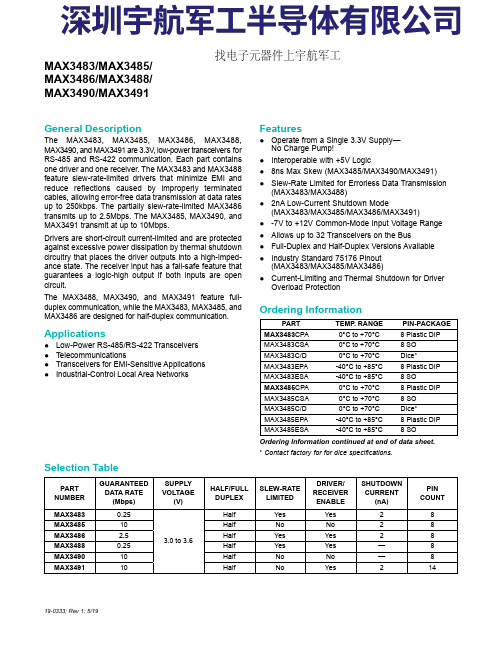
General Description The MAX3483, MAX3485, MAX3486, MAX3488,MAX3490, and MAX3491 are 3.3V , low-power transceivers forRS-485 and RS-422 communication. Each part containsone driver and one receiver. The MAX3483 and MAX3488feature slew-rate-limited drivers that minimize EMI andreduce reflections caused by improperly terminatedcables, allowing error-free data transmission at data ratesup to 250kbps. The partially slew-rate-limited MAX3486transmits up to 2.5Mbps. The MAX3485, MAX3490, andMAX3491 transmit at up to 10Mbps.Drivers are short-circuit current-limited and are protectedagainst excessive power dissipation by thermal shutdowncircuitry that places the driver outputs into a high-imped-ance state. The receiver input has a fail-safe feature thatguarantees a logic-high output if both inputs are opencircuit.The MAX3488, MAX3490, and MAX3491 feature full-duplex communication, while the MAX3483, MAX3485, andMAX3486 are designed for half-duplex communication.Applications ●Low-Power RS-485/RS-422 Transceivers ●Telecommunications ●Transceivers for EMI-Sensitive Applications ●Industrial-Control Local Area NetworksFeatures●Operate from a Single 3.3V Supply—No Charge Pump!●Interoperable with +5V Logic ●8ns Max Skew (MAX3485/MAX3490/MAX3491)●Slew-Rate Limited for Errorless Data Transmission (MAX3483/MAX3488)●2nA Low-Current Shutdown Mode (MAX3483/MAX3485/MAX3486/MAX3491)●-7V to +12V Common-Mode Input Voltage Range ●Allows up to 32 Transceivers on the Bus ●Full-Duplex and Half-Duplex Versions Available ●Industry Standard 75176 Pinout (MAX3483/MAX3485/MAX3486)●Current-Limiting and Thermal Shutdown for Driver Overload Protection 19-0333; Rev 1; 5/19Ordering Information continued at end of data sheet.*Contact factory for for dice specifications.PARTTEMP . RANGE PIN-PACKAGE MAX3483CPA0°C to +70°C 8 Plastic DIP MAX3483CSA0°C to +70°C 8 SO MAX3483C/D0°C to +70°C Dice*MAX3483EPA-40°C to +85°C 8 Plastic DIP MAX3483ESA-40°C to +85°C 8 SO MAX3485CPA0°C to +70°C 8 Plastic DIP MAX3485CSA0°C to +70°C 8 SO MAX3485C/D0°C to +70°C Dice*MAX3485EPA-40°C to +85°C 8 Plastic DIP MAX3485ESA -40°C to +85°C 8 SO PARTNUMBERGUARANTEED DATA RATE (Mbps)SUPPLY VOLTAGE (V)HALF/FULL DUPLEX SLEW-RATE LIMITED DRIVER/RECEIVER ENABLE SHUTDOWN CURRENT (nA)PIN COUNT MAX34830.25 3.0 to 3.6Half Yes Yes 28MAX348510Half No No 28MAX34862.5Half Yes Yes 28MAX34880.25Half Yes Yes —8MAX349010Half No No —8MAX349110Half No Yes 214MAX3483/MAX3485/MAX3486/MAX3488/MAX3490/MAX3491Selection TableOrdering Information找电子元器件上宇航军工Figure 1. MAX3483/MAX3485/MAX3486 Pin Configuration and Typical Operating Circuit Figure 2. MAX3488/MAX3490 Pin Configuration and Typical Operating Circuit Figure 3. MAX3491 Pin Configuration and Typical Operating CircuitMAX3486/MAX3488/MAX3490/MAX3491True RS-485/RS-422 TransceiversFigure 22. MAX3488/MAX3490/MAX3491 Full-Duplex RS-485 NetworkFigure 23. Line Repeater for MAX3488/MAX3490/MAX3491MAX3486/MAX3488/MAX3490/MAX3491True RS-485/RS-422 Transceivers。
MAX4211EEUE中文资料
4V TO 28V
+ -
+ -
25:1
IOUT POUT
1.21V REFERENCE INHIBIT
REF
CIN1+
COUT1 CIN1LE CIN2+ COUT2
µMAX is a registered trademark of Maxim Integrated Products, Inc. Pin Configurations and Selector Guide appear at end of data sheet.
MAX4211A MAX4211B MAX4211C GND
CIN2-
Functional Diagrams continued at end of data sheet. ________________________________________________________________ Maxim Integrated Products 1
For pricing, delivery, and ordering information, please contact Maxim/Dallas Direct! at 1-888-629-4642, or visit Maxim’s website at .
元器件交易网
MAX4210/MAX4211
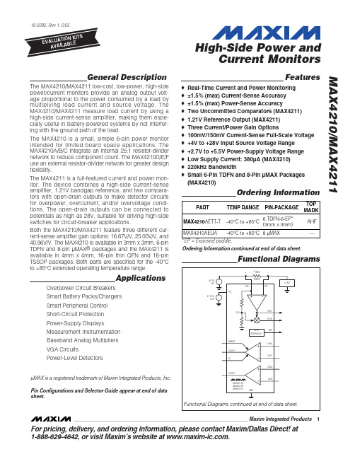
The MAX4210/MAX4211 low-cost, low-power, high-side power/current monitors provide an analog output voltage proportional to the power consumed by a load by multiplying load current and source voltage. The MAX4210/MAX4211 measure load current by using a high-side current-sense amplifier, making them especially useful in battery-powered systems by not interfering with the ground path of the load. The MAX4210 is a small, simple 6-pin power monitor intended for limited board space applications. The MAX4210A/B/C integrate an internal 25:1 resistor-divider network to reduce component count. The MAX4210D/E/F use an external resistor-divider network for greater design flexibility. The MAX4211 is a full-featured current and power monitor. The device combines a high-side current-sense amplifier, 1.21V bandgap reference, and two comparators with open-drain outputs to make detector circuits for overpower, overcurrent, and/or overvoltage conditions. The open-drain outputs can be connected to potentials as high as 28V, suitable for driving high-side switches for circuit-breaker applications. Both the MAX4210/MAX4211 feature three different current-sense amplifier gain options: 16.67V/V, 25.00V/V, and 40.96V/V. The MAX4210 is available in 3mm x 3mm, 6-pin TDFN and 8-pin µMAX® packages and the MAX4211 is available in 4mm x 4mm, 16-pin thin QFN and 16-pin TSSOP packages. Both parts are specified for the -40°C to +85°C extended operating temperature range.
阿里尔克斯35III摄影机产品说明书

ARRIFL
This new camera supplements the current ARRI FLEX 35 programme. In conjunction with the 35 BL II , it is the ideal 35 mm second unit camera. Highly mobile, robust and easy to service , this camera satisfies the most exacting requirements.
Viewfinder
The time-tested ARRIFLEX mirror reflex viewfinder system with rotating 1800 shutter has been retained. An automatic standstill circuit always stops the shutter at the viewing position when the camera is switched off. The interchangeable viewfinder groundglass screens with various format
ARRIFLEX 35 III with 500 ft VR magazine and two hand grips on body brace
ARRIFLEX 35 III with Cooke Varotal 20-100 mml T 3.1 and servo zoom, with 6.6" x 6.6" production matte box on bridge plate, with adapter plate
- 1、下载文档前请自行甄别文档内容的完整性,平台不提供额外的编辑、内容补充、找答案等附加服务。
- 2、"仅部分预览"的文档,不可在线预览部分如存在完整性等问题,可反馈申请退款(可完整预览的文档不适用该条件!)。
- 3、如文档侵犯您的权益,请联系客服反馈,我们会尽快为您处理(人工客服工作时间:9:00-18:30)。
For pricing, delivery, and ordering information,please contact Maxim/Dallas Direct!at 1-888-629-4642, or visit Maxim’s website at .General DescriptionThe MAX351/MAX352/MAX353 are precision, quad,single-pole single-throw (SPST) analog switches. The MAX351 has four normally closed (NC), and the MAX352has four normally open (NO) switches. The MAX353 has two NO and two NC switches. All three parts offer low on resistance (less than 35Ω), guaranteed to match within 2Ωbetween channels and to remain flat over the analog signal range (∆3Ωmax). They also offer low leakage (less than 250pA at +25°C and less than 6nA at +85°C) and fast switching (turn-on time less than 175ns and turn-off time less than 145ns).The MAX351/MAX352/MAX353 are fabricated with Maxim’s new improved 44V silicon-gate process. Design improve-ments guarantee extremely low charge injection (10pC), low power consumption (35µW), and electrostatic discharge (ESD) greater than 2000V. The 44V maximum breakdown voltage allows rail-to-rail analog signal handling.These monolithic switches operate with a single positive supply (+10V to +30V) or with split supplies (±4.5V to ±20V)while retaining CMOS-logic input compatibility and fast switching. CMOS inputs provide reduced input loading.________________________ApplicationsSample-and-Hold Circuits Military Radios Guidance and Control Systems Communications SystemsHeads-Up Displays Battery-Operated Systems Test EquipmentPBX, PABX____________________________Featureso Low On Resistance < 22ΩTypical (35ΩMax)o Guaranteed Matched On Resistance Between Channels < 2Ωo Guaranteed Flat On Resistance Over Analog Signal Range ∆3ΩMaxo Guaranteed Charge Injection < 10pCo Guaranteed Off-Channel Leakage < 6nA at +85°C o ESD Guaranteed > 2000V per Method 3015.7o Single-Supply Operation (+10V to +30V)Bipolar-Supply Operation (±4.5V to ±20V)o TTL-/CMOS-Logic Compatibilityo Rail-to-Rail Analog Signal Handling CapabilityMAX351/MAX352/MAX353Precision, Quad, SPST Analog Switches________________________________________________________________Maxim Integrated Products 1Pin Configurations/Functional Diagrams/Truth Tables19-0212; Rev 2; 9/01Ordering Information continued at end of data sheet.*Contact factory for availability and processing to MIL-STD-883.Ordering InformationM A X 351/M A X 352/M A X 353Precision, Quad, SPST Analog SwitchesABSOLUTE MAXIMUM RATINGSVoltage Referenced to V-V+.......................................................................................44V GND...................................................................................25V VL................................................(GND - 0.3V) to (V+ + 0.3V)Digital Inputs, V COM , V NC , V NO (Note 1)...........(V- - 2V) to (V+ + 2V).........................................................or 30mA (whichever occurs first)Current (any terminal).........................................................30mA Peak Current COM_, NO_, NC_(pulsed at 1ms, 10% duty cycle max)..........................100mA ESD per Method 3015.7..................................................>2000VContinuous Power Dissipation (T A = +70°C) (Note 2)Plastic DIP (derate 10.53mW/°C above +70°C)..........842mW Narrow SO (derate 8.70mW/°C above +70°C)............696mW QFN (derate 19.2mW/°C above +70°C)....................1538mW CERDIP (derate 10.00mW/°C above +70°C)...............800mW Operating Temperature Ranges:MAX35_C_ _.......................................................0°C to +70°C MAX35_E_ _.....................................................-40°C to +85°C MAX35_MJE ..................................................-55°C to +125°C Storage Temperature Range.............................-65°C to +150°C Lead Temperature (soldering, 10s).................................+300°CELECTRICAL CHARACTERISTICS —Dual Supplies(V+ = 15V, V- = -15V, VL = 5V, GND = 0V, V INH = 2.4V, V INL = 0.8V, T A = T MIN to T MAX , unless otherwise noted.)Stresses beyond those listed under “Absolute Maximum Ratings” may cause permanent damage to the device. These are stress ratings only, and functional operation of the device at these or any other conditions beyond those indicated in the operational sections of the specifications is not implied. Exposure to absolute maximum rating conditions for extended periods may affect device reliability.Note 1:Signals on NC_, NO_, COM_, or IN_ exceeding V+ or V- will be clamped by internal diodes. Limit forward diode current tomaximum current rating.Note 2:All leads are soldered or welded to PC board.MAX351/MAX352/MAX353Precision, Quad, SPST Analog SwitchesELECTRICAL CHARACTERISTICS —Dual Supplies (continued)(V+ = 15V, V- = -15V, VL = 5V, GND = 0V, V INH = 2.4V, V INL = 0.8V, T A = T MIN to T MAX , unless otherwise noted.)M A X 351/M A X 352/M A X 353Precision, Quad, SPST Analog Switches 4_______________________________________________________________________________________ELECTRICAL CHARACTERISTICS —Single Supply(V+ = 12V, V- = 0V, VL = 5V, GND = 0V, V INH = 2.4V, V INL = 0.8V, T A = T MIN to T MAX , unless otherwise noted.)Note 3:The algebraic convention, where the most negative value is a minimum and the most positive value a maximum, is used in this data sheet.Note 4:Guaranteed by design.Note 5:∆R ON = ∆R ON max - ∆R ON min. On-resistance match between channels and flatness are guaranteed only with bipolar-supply operation.Note 6:See Figure 5. Off Isolation = 20 log 10[ V COM ⁄ (V NC or V NO )], V COM = output, V NC or V NO = input to off switch.Note 7:Between any two switches. See Figure 6.MAX351/MAX352/MAX353Precision, Quad, SPST Analog Switches_______________________________________________________________________________________560-20-1010ON RESISTANCE vs. V COM AND POWER-SUPPLY VOLTAGE40V COM (V)R O N (Ω)02020503010700-20-1010ON RESISTANCE vs. V COM ANDTEMPERATURE50V COM (V)R O N (Ω)0203010402060200515ON RESISTANCE vs. V COM ANDTEMPERATURE120V COM (V)R O N (Ω)102080401006014016020515ON RESISTANCE vs. V COM(SINGLE-SUPPLY)70V COM (V)R O N (Ω)10205030604080-60-20CHARGE INJECTION vs.ANALOG VOLTAGE40V COM (V)Q (p C )0200-4020-2060-15-10-5510150.0001-55OFF LEAKAGE CURRENTS vs.TEMPERATURE10TEMPERATURE (°C)O F F L E A K A G E (n A )+25+1250.10.00110.011000.0001-55ON LEAKAGE CURRENTS vs.TEMPERATURE10TEMPERATURE (°C)O N L E A K A G E (n A )+25+1250.10.00110.011000.0001-55SUPPLY CURRENT vs. TEMPERATURE10TEMPERATURE (°C)I +, I -, I L (µA )+25+1250.10.00110.01100__________________________________________Typical Operating Characteristics(T A = +25°C, unless otherwise noted.)M A X 351/M A X 352/M A X 353__________Applications InformationOperation with Supplies Other than ±15VThe main limitation of supply voltages other than ±15V is reduced analog-signal range. The MAX351/MAX352/MAX353 operate with ±5V to ±20V bipolar supplies. The Typical Operating Characteristics graphs show typical on resistance (R ON ) for ±15V, ±10V, and ±5V supplies. (Switching times increase by a factor of two or more for operation at ±5V.) The MAX351/MAX352/MAX353 can operate from +10V to +30V unipolar supplies. Each device can also be powered from unbalanced supplies such as +24V and -5V.Connect V- to 0V when operating with a single supply.VL must be connected to +5V to be TTL compatible or to V+ for CMOS-logic input levels.Overvoltage ProtectionProper power-supply sequencing is recommended for all CMOS devices. Do not exceed the absolute maxi-mum ratings because stresses beyond the listed rat-ings may cause permanent damage to the devices.Always sequence V+ first, followed by VL, V-, and logic inputs. If power-supply sequencing is not possible, add two small signal diodes in series with the supply pins for overvoltage protection (Figure 1). Adding diodes reduces the analog signal range to 1V below V+ and 1V below V-, but low switch resistance and low-leakage characteristics are unaffected. Device operation is unchanged, and the difference between V+ to V-should not exceed +44V.Precision, Quad, SPST Analog Switches 6_______________________________________________________________________________________Figure 1. Overvoltage Protection Using External Blocking DiodesMAX351/MAX352/MAX353Precision, Quad, SPST Analog Switches_______________________________________________________________________________________7Figure 2. Switching-Time Test CircuitFigure 3. Break-Before-Make Test Circuit (MAX353 only)______________________________________________Test Circuits/Timing DiagramsM A X 351/M A X 352/M A X 353Precision, Quad, SPST Analog Switches 8_______________________________________________________________________________________Figure 6. Crosstalk Test CircuitFigure 5. Off-Isolation Test Circuit _________________________________Test Circuits/Timing Diagrams (continued)MAX351/MAX352/MAX353Precision, Quad, SPST Analog Switches_________________________________Test Circuits/Timing Diagrams (continued)Pin Configurations (continued)Figure 7. Channel-Off Capacitance Figure 8. Channel-On Capacitance Test CircuitM A X 351/M A X 352/M A X 353Precision, Quad, SPST Analog Switches 10_________________________________________________________________________________________________________Chip TopographyCOM30.080"(2.03mm)IN4IN3TRANSISTOR COUNT: 136SUBSTRATE CONNECTED TO V+A B C A B C MAX351MAX352MAX353NAME NAME PIN PIN NC NC NC NO NO NO *Contact factory for availability and processing to MIL-STD-883.Ordering Information (continued)MAX351/MAX352/MAX353Precision, Quad, SPST Analog SwitchesPackage Information(The package drawing(s) in this data sheet may not reflect the most current specifications. For the latest package outline information,go to /packages .)M A X 351/M A X 352/M A X 353Precision, Quad, SPST Analog Switches 12______________________________________________________________________________________Package Information (continued)(The package drawing(s) in this data sheet may not reflect the most current specifications. For the latest package outline information,go to /packages .)MAX351/MAX352/MAX353Precision, Quad, SPST Analog SwitchesMaxim cannot assume responsibility for use of any circuitry other than circuitry entirely embodied in a Maxim product. No circuit patent licenses are implied. Maxim reserves the right to change the circuitry and specifications without notice at any time.Maxim Integrated Products, 120 San Gabriel Drive, Sunnyvale, CA 94086 408-737-7600 ____________________13©2001 Maxim Integrated ProductsPrinted USAis a registered trademark of Maxim Integrated Products.Package Information (continued)(The package drawing(s) in this data sheet may not reflect the most current specifications. For the latest package outline information,go to /packages .)。