Mankiw 6e PowerPoints
艾森 Moeller 系列 PKZM0 电机保护开关说明书

Eaton 199193Eaton Moeller® series PKZM0 Motorschutzschalter, 0,25 kW, 0,63 - 1 A, Einspeiseseitig Schraubklemmen/Abgangsseitig Push-in-Klemmen, MSCAllgemeine spezifikationEaton Moeller® series PKZM0 Motor-protective circuit-breaker19919375 mm102 mm 45 mm 0.274 kgVDE 0660 IEC/EN 60947 UL File No.: E36332 IEC/EN 60947-4-1 CSA File No.: 165628UL Category Control No.: NLRV ULCSA-C22.2 No. 60947-4-1-14 CSA Class No.: 3211-05 CSAUL 60947-4-1 CE UL CSA4015081972777PKZM0-1-SPI32ProduktnameKatalognummer Produkt Länge/Tiefe Produkthöhe Produktbreite Produktgewicht Zertifikat(e)EANModellcodeDrehknopfPhasenausfallempfindlichkeit (gemäß IEC/EN 60947-4-1, VDE 0660 Teil 102)MotorschutzPhasenausfallempfindlich3-polig 100.000 Schaltvorgänge100.000 SchaltvorgängeHutschienenmontage optionalAufschnappbar auf Hutschiene IEC/EN 60715 mit 7,5 oder 15 mm Höhe.40 Schaltspiele/hIII3MotorschutzschalterFinger- und handrückensicher, Berührungsschutz bei senkrechter Betätigung von vorne (EN 50274)6000 V AC25 g, Mechanisch, entsprechend IEC/EN 60068-2-27, Halbsinusstoß 10 msAuch Motoren mit Effizienzklasse IE3Nebenstromkreis: Manueller Typ E bei Einsatz mit Klemme, oder geeignet für Gruppeninstallationen, (UL/CSA)≤ 0,25 %/K, Restfehler für T > 40°-25 - 55 °C, Arbeitsbereich-5 - 40 °C gemäß IEC/EN 60947, VDE 0660Motorstarterkombinationen Typ MSC…Stellgliedtyp Merkmale Funktionen Polzahl Lebensdauer, elektrischLebensdauer, mechanisch MontagemethodeEinbaulageBetriebsfrequenzÜberspannungskategorie VerschmutzungsgradProduktkategorieSchutzBemessungsstoßspannungsfestigkeit (Uimp) SchockfestigkeitGeeignet fürTemperaturkompensationVerwendet mitMax. 2000 m-25 °C55 °C-25 °C40 °C-40 °C80 °CFeuchte Wärme, konstant, nach IEC 60068-2-78 Feuchte Wärme, zyklisch, nach IEC 60068-2-301 x (1 - 6) mm²12 mm1,7 Nm, Schraubklemmen, Hauptleiter50 Hz60 Hz1 A0.12 kW0.25 kW690 V690 V1 A50 kA, 600 Y/347 V, SCCR (UL/CSA)65 kA, 240 V, SCCR (UL/CSA)65 kA, 480 Y/277 V, SCCR (UL/CSA)± 20% Toleranz, Auslöserblöcke15,5 A, Irm, Einstellbereich max.Grundgerät befestigt 15,5 x lu, Auslöserblöcke Einspeiseseitige Schraubklemmen Abgangsseitige Push-In-KlemmenHöheUmgebungsbetriebstemperatur – min Umgebungsbetriebstemperatur – max Umgebungsbetriebstemperatur (gekapselt) – min Umgebungsbetriebstemperatur (gekapselt) – max Umgebungstemperatur Lagerung - min Umgebungstemperatur Lagerung - max Klimafestigkeit Anschlusskapazität (feindrähtig)Abisolierlänge (Hauptleiter)AnzugsdrehmomentBemessungsfrequenz - minBemessungsfrequenz - max Bemessungsbetriebsstrom (Ie) Bemessungsbetriebsleistung bei AC-3, 220/230 V, 50 Hz Bemessungsbetriebsleistung bei AC-3, 380/400 V, 50 Hz Bemessungsbetriebsspannung (Ue) - min Bemessungsbetriebsspannung (Ue) - max Bemessungsdauerstrom (Iu)Bemessungskurzschlussstrom (Typ E)KurzschlussauslöserVerbindungAnzahl der Hilfskontakte (Wechsler)0 1 A1 AÜberlastauslöser: Auslöseklasse 10 A5.33 W0 W0 W0 WAnforderungen der Produktnorm sind erfüllt.Anforderungen der Produktnorm sind erfüllt.Anforderungen der Produktnorm sind erfüllt.Anforderungen der Produktnorm sind erfüllt.Anforderungen der Produktnorm sind erfüllt.Unzutreffend, da die gesamten Schaltgeräte überprüft werden müssen.Unzutreffend, da die gesamten Schaltgeräte überprüft werden müssen.Anforderungen der Produktnorm sind erfüllt.DA-DC-00004917.pdfDA-DC-00004887.pdfETN.PKZM0-1-SPI32.edzIL122024ZUWIN-WIN mit Push-in-TechnikProduktübersicht für den Maschinenbau Sortimentskatalog Motoren schalten und schützenpkzm0_s32_pi.stppkzm0_s32_pi.dwgeaton-manual-motor-starters-pkz-dimensions-002.eps121X002121X042eaton-manual-motor-starters-pkzm-pkzm0-dimensions-003.eps eaton-manual-motor-starters-pkz-dimensions.epsAnzahl der Hilfskontakte (Öffner)Anzahl Hilfskontakte (Schließer)Überlastauslösestromeinstellung - minÜberlastauslösestromeinstellung - maxAuslösecharakteristikGeräteverlustleistung, stromabhängig pvid Verlustleistungskapazität PdissVerlustleistung pro Pol, stromabhängig, PvidStatische Verlustleistung, stromunabhängig PVS10.2.2 Korrosionsbeständigkeit10.2.3.1 Wärmebeständigkeit von Umhüllung10.2.3.2 Widerstandsfähigkeit Isolierstoffe gewöhnliche Wärme 10.2.3.3 Widerst. Isolierstoffe abnorm. Wärme/Feuer durch int. elektr. Auswirk.10.2.4 Beständigkeit gegen UV-Strahlung10.2.5 Heben10.2.6 Schlagprüfung10.2.7 Beschriftungen Declarations of conformity eCAD model Installationsanleitung Installationsvideos KatalogemCAD model Zeichnungen10.3 Schutzart von BaugruppenUnzutreffend, da die gesamten Schaltgeräte überprüft werden müssen.10.4 Luft- und KriechstreckenAnforderungen der Produktnorm sind erfüllt.10.5 Schutz gegen elektrischen SchlagUnzutreffend, da die gesamten Schaltgeräte überprüft werden müssen.10.6 Einbau von BetriebsmittelnUnzutreffend, da die gesamten Schaltgeräte überprüft werden müssen.10.7 Innere Stromkreise und VerbindungenLiegt in der Verantwortung des Schaltanlagenbauers.10.8 Anschlüsse für von außen eingeführte LeiterLiegt in der Verantwortung des Schaltanlagenbauers.10.9.2 Betriebsfrequente SpannungsfestigkeitLiegt in der Verantwortung des Schaltanlagenbauers.10.9.3 StoßspannungsfestigkeitLiegt in der Verantwortung des Schaltanlagenbauers.10.9.4 Prüfung von Umhüllungen aus IsolierstoffLiegt in der Verantwortung des Schaltanlagenbauers.10.10 ErwärmungDie Erwärmungsberechnung liegt in der Verantwortung des Schaltanlagenbauers. Eaton stellt Verlustleistungsdaten der Geräte bereit.10.11 KurzschlussfestigkeitLiegt in der Verantwortung des Schaltanlagenbauers. Die Spezifikationen für die Schaltgeräte müssen beachtet werden.10.12 Elektromagnetische VerträglichkeitLiegt in der Verantwortung des Schaltanlagenbauers. Die Spezifikationen für die Schaltgeräte müssen beachtet werden.10.13 Mechanische FunktionDas Gerät erfüllt die Anforderungen, wenn die Informationen in der Montageanweisung (IL) beachtet werden.Eaton Konzern plc Eaton-Haus30 Pembroke-Straße Dublin 4, Irland © 2023 Eaton. Alle Rechte vorbehalten. Eaton ist eine eingetrageneMarke.Alle anderen Warenzeichen sindEigentum ihrer jeweiligenBesitzer./socialmedia。
Modicon M172 Performance Blind 42 I Os 产品数据手册说明书

i s c l a i me r : T h i s d o c u m e n t a t i o n i s n o t i n t e n d e d a s a s u b s t i t u t ef o r a n d i s n o t t o b e u s e d f o r d e t e r m i n i ng s u i t a b i l i t y o r r e l i a b i l i t y o f th e s e p r o d u c t s f o r s p e ci f i c u s e r a p p l i c a t i o n sMainRange of productModicon M171/M172Product or component typeProgrammable controllers Product specific applicationHVAC and pumping solution VariantProgrammable Number of inputs/outputs42Discrete input number12Discrete output number 2 for relay outputs SPST with same common2 for relay outputs SPST with independent common2 for relay outputs SPDT with same common3 for relay outputs SPST with independent commonDiscrete output current 1 A for relay SPDT3 A for relay SPSTAnalogue input number12 configurable by pair ComplementaryNumber of port 1 CAN port - screw terminal block1 USB type A - USB type A female1 USB type mini B - USB device port Mini-B2 RS485 - screw terminal block (Modbus serial link or BACnet MS/TP)1 Ethernet - RJ45 (Modbus TCP and BACnet IP with webserver)Input/Output number 12 analog input(s)6 analog output(s)12 digital input(s)12 digital output(s)Discrete input logic Sink or source (positive/negative)Discrete input voltage 24 V AC/DCDiscrete input current 2.5 mAInput impedance 20 kOhmAnalogue input type Direct inputImpedance 0...1500 hOhmImpedance 0...300 daOhmVoltage 0...5 V (absolute or ratiometric)Power consumption in W15 W at 24 V AC/DCRealtime clock Built-in realtime clock at -20...60 °CDisplay type Without displayOvervoltage category IILocal signalling 1 LED red programmable1 LED yellow programmable1 LED green programmable1 LED green powerMounting support DIN railPanel mounting with accessoryWidth144 mmHeight110 mmDepth60.5 mmProduct weight0.385 kgEnvironmentDirectives2006/95/EC - low voltage directive1907/2006/EC - REACH directive2011/65/EU - RoHS directive86/188/EEC - physical agents (noise) directiveStandards EN/IEC 60730Product certifications CECSA (pending)cURus (pending)EAC (pending)Ambient air temperature for operation-20...60 °C conforming to UL 60730-1-20...65 °C with derating conforming to UL 60730-1Ambient air temperature for storage-30...70 °CRelative humidity 5...95 % non-condensingIP degree of protection IP20Pollution degree2Offer SustainabilitySustainable offer status Not Green Premium productRoHS (date code: YYWW)Compliant - since 1530 - Schneider Electric declaration of conformitySchneider Electric declaration of conformityREACh Reference not containing SVHC above the thresholdReference not containing SVHC above the thresholdDIN Rail MountingClips for Panel MountingPanel MountingIncorrect Mounting PositionAssembling a ModuleWiring Sections and Torque A, C, D, E, F, G, HBLogic Controller ConnectorsPower Supply(1)Type T fuse 2 ADigital InputsThe COM_DI terminals are not connected internally. Fast Digital InputsPulse / Frequency counter up to 2 kHz.The Cx terminals are not connected internally.Analog Inputs(1)(CN5 + CN13) Max. current: 50 mA.(2)(CN5 + CN13) Max. current: 150 mA.Analog OutputsAO3, AO4 can be used also as PWM generator, up to 2 kHz.RS 485 - Modbus SL or BACnet MS/TPApply 120 Ω terminal resistance.。
艾桑 Moeller 系列快速连接反转启动器 199080说明书

Eaton 199080Eaton Moeller® series Rapid Link - Reversing starter, 6.6 A,Sensor input 2, AS-Interface®, S-7.4 for 31 modules, HAN Q4/2Especificaciones generalesEaton Moeller® series Rapid LinkReversing starter1990804015081971381120 mm270 mm220 mm 1.63 kgCCCRoHSUL 60947-4-2CEIEC/EN 60947-4-2 UL approval Assigned motor rating: for normal internally and externally ventilated 4 pole, three-phase asynchronous motors with 1500 rpm at 50 Hz or 1800 min at 60 HzRAMO5-W200A31-4120S1Product Name Catalog NumberEANProduct Length/Depth Product Height Product Width Product Weight Certifications Catalog NotesModel CodeParameterization: drivesConnect mobile (App)Diagnostics and reset on device and via AS-Interface Parameterization: KeypadParameterization: drivesConnectParameterization: FieldbusKey switch position HANDThermistor monitoring PTCKey switch position AUTOKey switch position OFF/RESETTwo sensor inputs through M12 sockets (max. 150 mA) for quick stop and interlocked manual operationElectronic motor protectionThermo-clickShort-circuit releaseExternal reset possibleTemperature compensated overload protection CLASS 10 AIP65NEMA 12Class A10,000,000 Operations (at AC-3)10,000,000 Operations (at AC-3)Reversing starter0.3 A6.6 AIIIMotor starterAS-Interface profile cable: S-7.4 for 31 modulesASI4000 VPhase-earthed AC supply systems are not permitted. Center-point earthed star network (TN-S network) AC voltageReversing starterDCFeatures Fitted with: Functions ClassDegree of protectionElectromagnetic compatibility Lifespan, electricalLifespan, mechanicalModelOverload release current setting - min Overload release current setting - max Overvoltage categoryProduct categoryProtocolRated impulse withstand voltage (Uimp) System configuration typeTypeVoltage typeVertical15 g, Mechanical, According to IEC/EN 60068-2-27, 11 ms, Half-sinusoidal shock 11 ms, 1000 shocks per shaftResistance: 10 - 150 Hz, Oscillation frequencyResistance: 6 Hz, Amplitude 0.15 mmResistance: 57 Hz, Amplitude transition frequency on accelerationResistance: According to IEC/EN 60068-2-6Above 1000 m with 1 % performance reduction per 100 m Max. 1000 mMax. 2000 m-10 °C55 °C-40 °C70 °C< 95 %, no condensationIn accordance with IEC/EN 501780.3 - 6.6 A, motor, main circuit Adjustable, motor, main circuit6.6 A (at 150 % Overload)Maximum of one time every 60 seconds380 - 480 V (-15 %/+10 %, at 50/60 Hz)20 - 35 ms20 - 35 ms50/60 HzAC-53a 3 HP10 kA0 AType 1 coordination via the power bus' feeder unit, Main circuit0 V0 VMounting position Shock resistance Vibration AltitudeAmbient operating temperature - min Ambient operating temperature - max Ambient storage temperature - min Ambient storage temperature - max Climatic proofingCurrent limitationInput currentMains switch-on frequency Mains voltage tolerance Off-delayOn-delayOutput frequency Overload cycleRated frequency - min Assigned motor power at 460/480 V, 60 Hz, 3-phaseRated conditional short-circuit current (Iq)Rated conditional short-circuit current (Iq), type 2, 380 V, 400 V, 415 VShort-circuit protection (external output circuits)Rated control supply voltage (Us) at AC, 50 Hz - minRated control supply voltage (Us) at AC, 50 Hz - max47 Hz63 Hz6.6 A6.6 A6.6 A0.09 kW3 kW0 kW3 kW480 V AC, 3-phase 400 V AC, 3-phase 50/60 Hz, fLN, Main circuit Phase-earthed AC supply systems are not permitted. Center-point earthed star network (TN-S network) AC voltage0 V0 V0 V0 V24 V DC (-15 %/+20 %, external via AS-Interface® plug)Connections pluggable in power section Specification: S-7.4 (AS-Interface®)Number of slave addresses: 31 (AS-Interface®)Max. total power consumption from AS-Interface® power supply unit (30 V): 190 mA10 m, Radio interference level, maximum motor cable lengthMeets the product standard's requirements.Meets the product standard's requirements.Meets the product standard's requirements.Meets the product standard's requirements.Rated frequency - max Rated operational current (Ie)Rated operational current (Ie) at 150% overload Rated operational current (Ie) at AC-3, 380 V, 400 V, 415 V Rated operational power at 380/400 V, 50 Hz - min Rated operational power at 380/400 V, 50 Hz - max Rated operational power at AC-3, 220/230 V, 50 Hz Rated operational power at AC-3, 380/400 V, 50 Hz Rated operational voltage Supply frequencySystem configuration typeRated control supply voltage (Us) at AC, 60 Hz - min Rated control supply voltage (Us) at AC, 60 Hz - max Rated control supply voltage (Us) at DC - min Rated control supply voltage (Us) at DC - max Rated control voltage (Uc)ConnectionInterfacesNumber of auxiliary contacts (normally closed contacts)Number of auxiliary contacts (normally open contacts)Cable length10.2.2 Corrosion resistance10.2.3.1 Verification of thermal stability of enclosures 10.2.3.2 Verification of resistance of insulating materials to normal heat10.2.3.3 Resist. of insul. mat. to abnormal heat/fire by internal elect. effectsMeets the product standard's requirements.Does not apply, since the entire switchgear needs to be evaluated.Does not apply, since the entire switchgear needs to be evaluated.Meets the product standard's requirements.Does not apply, since the entire switchgear needs to be evaluated.Meets the product standard's requirements.Does not apply, since the entire switchgear needs to be evaluated.Does not apply, since the entire switchgear needs to be evaluated.Is the panel builder's responsibility.Is the panel builder's responsibility.Is the panel builder's responsibility.Is the panel builder's responsibility.Is the panel builder's responsibility.The panel builder is responsible for the temperature rise calculation. Eaton will provide heat dissipation data for the devices.Is the panel builder's responsibility. The specifications for the switchgear must be observed.eaton-bus-adapter-rapidlink-speed-controller-dimensions-002.eps eaton-bus-adapter-rapidlink-speed-controller-dimensions-003.eps eaton-bus-adapter-rapidlink-reversing-starter-dimensions.epseaton-bus-adapter-rapidlink-reversing-starter-dimensions-002.epsETN.RAMO5-W200A31-4120S1.edzRapid Link 5 - brochureDA-SW-USB Driver PC Cable DX-CBL-PC-1M5DA-SW-Driver DX-CBL-PC-3M0DA-SW-drivesConnect - InstallationshilfeDA-SW-drivesConnect - installation helpDA-SW-drivesConnectDA-SW-USB Driver DX-COM-STICK3-KITMaterial handling applications - airports, warehouses and intra-logisticsDA-DC-00004523.pdfDA-DC-00003964.pdfDA-DC-00004184.pdfDA-DC-00004525.pdfIL034084ZUramo5_v7.dwgramo5_v7.stpConfiguration to Rockwell PLC for Rapid LinkGeneration Change RASP4 to RASP5Generation change from RA-SP to RASP 4.0Generation change RAMO4 to RAMO5Generation change from RA-MO to RAMO 4.0Generation Change RA-SP to RASP510.2.4 Resistance to ultra-violet (UV) radiation10.2.5 Lifting10.2.6 Mechanical impact10.2.7 Inscriptions10.3 Degree of protection of assemblies10.4 Clearances and creepage distances10.5 Protection against electric shock10.6 Incorporation of switching devices and components 10.7 Internal electrical circuits and connections10.8 Connections for external conductors10.9.2 Power-frequency electric strength10.9.3 Impulse withstand voltage10.9.4 Testing of enclosures made of insulating material 10.10 Temperature rise10.11 Short-circuit rating10.12 Electromagnetic compatibility DibujoseCAD modelFolletosInformes de certificaciónInstrucciones de montaje mCAD modelNotas de aplicaciónEaton Corporation plc Eaton House30 Pembroke Road Dublin 4, Ireland © 2023 Eaton. All Rights Reserved. Eaton is a registered trademark.All other trademarks areproperty of their respectiveowners./socialmediaIs the panel builder's responsibility. The specifications for the switchgear must be observed.The device meets the requirements, provided the information in the instruction leaflet (IL) is observed.10.13 Mechanical function。
SIEMENS 6RM70全数字直流调速柜 说明书

SIMOREG DC-MASTER使用说明书6RM70全数字直流调速柜版本:AB内部索引号:058 100.0003.0103.2003目 录Siemens Electrical Drives Ltd. 058 100.0003.010-1SIMOREG DC-MASTER 6RM70 使用说明书目 录定 义.........................................................................................................................................0-21电路简图.....................................................................................................................................1-12运输、拆包装、安装...................................................................................................................2-12.1运输和拆包装..............................................................................................................................2-12.2贮 存.........................................................................................................................................2-12.3安 装.........................................................................................................................................2-23连 接.........................................................................................................................................3-13.1主回路和励磁回路接线...............................................................................................................3-13.2电机风机接线..............................................................................................................................3-23.3柜内匹配变压器..........................................................................................................................3-23.4电机转速测量信号......................................................................................................................3-33.4.1模拟测速机的选择和使用............................................................................................................3-33.4.2模拟测速机的连接......................................................................................................................3-33.4.3脉冲编码器的选择和使用............................................................................................................3-33.4.4脉冲编码器的连接......................................................................................................................3-43.5外部速度给定信号......................................................................................................................3-43.6外部启动、允许信号...................................................................................................................3-43.7输出信号.....................................................................................................................................3-53.8抑制无线电干扰的措施...............................................................................................................3-54启 动.........................................................................................................................................4-14.1柜门上操作开关说明...................................................................................................................4-24.2启动的操作步骤..........................................................................................................................4-25维 护.........................................................................................................................................5-16技术数据.....................................................................................................................................6-17订货和设计数据..........................................................................................................................7-1定 义03.20030-2Siemens Electrical Drives Ltd. 058 100.0003.01SIMOREG DC-MASTER 6RM70 使用说明书0 定 义合格人员为了理解本使用说明书和产品上的警示标记,“合格人员”是指熟悉本产品的装配、安装、启动、运行和存在的危险。
梯度开关模块CSM 1277连接SIMATIC S7-1200及更多其他Industry Ether

EN 61000-6-2, EN 61000-6-4
● C-Tick
Yes
● KC approval
No
Standards, specifications, approvals / ship classification
Marine classification association
● American Bureau of Shipping Europe Ltd.
Design, dimensions and weight Design Width Height Depth Net weight Mounting type ● 35 mm DIN rail mounting ● wall mounting ● S7-300 rail mounting ● S7-1500 rail mounting
/snst
/simatic-net https:// /industry/infocenter /bilddb /cax https://
Yes Yes No No
No No
Yes
No
6GK7277-1AA10-0AA0 Page 2/4
11/30/2017
Subject to change without notice © Copyright Siemens
Standard ● for FM
● for hazardous zone
Data sheet
6GK7277-1AA10-0AA0
COMPACT SWITCH MODULE CSM 1277 CONNECTION SIMATIC S7-1200 AND UP TO 3 FURTHER IND. ETHERNET USERS WITH 10/100 MBIT/S UNMANAGED SWITCH, 4 RJ45 PORTS, EXT. 24V DC POWER SUPPLY, LED DIAGNOSTICS, S7-1200 MODULE INCL. ELECTRONIC MANUAL ON CD
Modus自动大门驱动器说明书

ENKGModus1.2. 3.PATENTED PERFORMANCESThanks to its patented mechanics, Modus can automate big gates with dimensions up to 4.2 m and 500 kg. It has a precise mechanical limit switchadjustement of the wingin opening and closing.Easy and fast to install withits 165 mm of width, available in two motor versions withtwo standard arms and two optional arms with slidingand rotating features for every type of installation.4 kilograms of aluminum,4-stage gear box entirelyin stainless and high-quality synthetic lubricant make Modus a indestructible automation and can be used at any temperature.The 24 V motor allows intensive use installations.SMART TRADITIONALELECTRONICSSTARG8 control units radicallysimplify the installer’s job,guaranteeing high levelsof performance in termsof safety, time and speedof installation.A single programming methodspeeds up the activationof the automatic devicesand managing maintenanceoperations becomes simpleand practical.NEW MOTORFOR MODUS XLMODUS XL new transmissionguarantees maximum reliabilityand mechanical resistance evenfor challenging installationsthanks to a more powerful gearmotor.Automation for swing gateswith leaves up to 4.2 m - 500 kg1. CONTROL UNITFast regulation with trimmersand dip-switches, programmingwith self-learning function2. ARTICULATED ARMStrong die-cast aluminium armwith anti-shearing device3. MECHANICAL LIMITSWITCHStrong adjustable steellimit switchHousingfor control unitProtected releasesystemDie-cast aluminiumframeMODUS MAMODUS SL NOVO PH 180NOVO LED PLUSIDEA 24 PLUSKits include the arm MO LINK 420.24 V version also available for markets with 110 V / 60 Hz mains power supplyGear motors Modus don’t include the arm of connection to the leaf. It is necessary to choose the most suitable arm for the gate in the list of the following page.MO L C18 SXSliding arm for leavesup to 1.8 m - 300 kg.Left versionBK 40Mechanical limit switch(2 pieces)LOCK VEVerticalelectro lock 12 VMO L C18 DXSliding arm for leavesup to 1.8 m - 300 kg.Right versionSBLO 800External releasewith wire rope includedMO Link R42Rotative arm(Inclination +/- 8°)Leaves max dimensions4.2 m - 500 kgBAT M01624 V 1.6 Ah battery24 Vdc spare control unitMO LINK 180For leaves up to 1.8 m.Distance between the axleof rotation of the gate andmotor 200 mmBAT K3Battery charge cardfor BAT M016MO LINK 420For leaves up to 4.2 m.Distance between the axleof rotation of the gate andmotor 350 mmLOCK HOHorizontalelectro lock 12 V CONNECTION ARMSACCESSORIESLIMITS OF USE FOR THE PRODUCTPanel max length (mm)Panelmaxweight(kg)C(mm)A (mm)External lever release withwire rope includedKING GATES srl Via A. Malignani 4233077 Sacile (PN) Italy Ph. +39 0434 737082Fax +39 0434 786031*******************the king specialistKINGspecialist app for installers The KINGspecialist app allows youto complete all installation setup phases directly from your smart phone or tablet.Thanks to the wifi module,which can be coupled to STARG8 central units,every professional can now manage all the functions offered by the KING Smart Traditional electronic device simply and intuitively.The App also introduces new functions, such asscheduling of periodical system maintenance, central unit check-ups and remote control management.KINGgates relies on a network of expert professional installers.KINGspecialist is a programme available onlyto installers: KINGgates quality in the form of a service. Installer-friendly innovations and continuous updates to keep growing together.。
罗克韦尔 运动坐标系统1756-HYD02 1756-M02AE 说明书.

艾默斯火器6720E型号的装配说明书
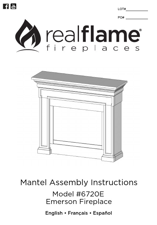
Mantel Assembly InstructionsEmerson FireplaceModel #6720E98Center Panel 123456789Nu./Nú.Description/Descripción Cdt./No. Description Qty 1 Top Panel12 Left Side Panel1Panneau latéral gauche/Panel lateral izquierdo3Right Side Panel1 Panneau latéral droit/Panel lateral derecho4 Left Front Panel1 Panneau avant gauche/Panel delantero izquierdo5 Right Front Panel1 Panneau avant droit/Panel delantero derecho617Lower Firebox Trim1Cantidad1011Right Firebox Trim 1Moulure droite/Reborde decorativo derecho del hogar Left Firebox Trim 1Moulure gauche/Reborde decorativo izquierdo del hogar 10Upper Firebox Trim 111Firebox Support 1 67208201 67208202 67208203 67208204 67208205 67208206 67200007 67200009 6720000867200010 67200011Parts List - Liste de Pièces - Lista de PiezasPanneau central/Panel centralPanneau supérieur/Panel superiorMoulure inférieure/Reborde decorativo inferior del hogar Moulure supérieure/Reborde decorativo superior del hogar Support pour le foyer/Soporte del hogar 12Hardware Kit 1Ensemble de quincaillerie/Kit de hardware13Anti-Topple Device 1Dis p ositif Anti-Renversement/ Dis positivo Anti-Derrocar10032 10032 6720001267200601 67200602 67200603 67200604 67200605 67200606 67200007 67200009 67200008 67200010 67200011 6720001267200012Hardware Kit-Quincaillerie/ Kit de Hardware16x21x1x8x21xShort Allen Screw L-BracketFerrure en L/ Soporte de LWasherRondelle/ ArandelaAllen WrenchClé Allen/ Llave AllenVis allen courte/ Tornillo allen cortLong Allen ScrewLongue vis allen/ Tornillo allen largox xWallx2x11.x1x1x2x2x22.3.StudWallStudAnti-Topple Device InstallationThis product is not a substitute for parental supervision. Real Flame® assumes no responsibility or liability for improper installation or excessive loads placed on any of the supplied components.Note: Your mantel may vary slightly from the one depicted in this illustration.Note: Locate the top of this bracket 3” below the top of theassembled mantel.Follow all instructions included with yourReal Flame® mantel and firebox.Real Flame® Customer Service: 1-800-654-1704!CAUTIONIf a stud is not accessible, use the included drywall anchors to secure the wall bracket.!NOTEParts List - 10032x1Lire complètement l’étiquette et toutes les instructions du produits Real Flame®.Siga todas las instrucciones que vienen con su chimenea Real Flame ® y cámara de combustión.16Limited Warranty Real Flame® warrants that the following components of this Real Flame® fireplace ("the Product") will be free from manufacturing defects in material and workmanship after correct assembly and under normal use and proper maintenance for the periods indicated below, commencing with the date of purchase of the Product:• The body – 1 year limited warranty.This warranty extends to the original purchaser only, provided that the purchase was made through an authorized Real Flame dealer. The warranty is also subject to the following conditions and limitations:This warranty does not extend to damages caused by shipping, improper assembly, installation or storage, installation that does not comply with building codes and ordinances, installation or operation not in accordance with the included manual, abuse, lack of maintenance, hostile environments, accident, natural weather, or unworkmanlike repairs. Modification of the Product, use of fuels other than what is approved by Real Flame, or use of parts installed from other manufactures will nullify this warranty. This warranty applies to the functionality of the Product only and does not cover cosmetic issues such as scratches, dents, rust, oxidation, corrosion, or discoloring caused by heat, abrasive cleaners and chemical cleaners. However, should deterioration of parts occur to the degree of non-performance within the duration of the warranty period, Real Flame will provide a replacement part. Real Flame requires reasonable proof of your date of purchase. Therefore, you should retain your sales receipt and/or invoice. Defective parts subject to this warranty will not be replaced without proof of purchase.Real Flame must have the opportunity to verify the alleged defect. In order for any internal components to be covered under warranty, Real Flame requires the user to troubleshoot with a Real Flame Customer Service member to ensure proper operation and diagnosis of issue. In the event of covered defects in warrantied items, Real Flame will, at its sole option and discretion, replace the defective component, replace the Product or refund the purchase price. Real Flame is not responsible for the installation, labor or any other costs associated with the reinstallation. The foregoing is the exclusive remedy under the terms of this limited warranty. Real Flame will not be responsible for any incidental or consequential damages caused by defects in the Product. Some states do not allow the exclusion or limitation of incidental or consequential damages, so the above limitation or exclusion may not apply to you.This limited warranty is the sole express warranty given by Real Flame. The duration of any implied warranty arising under the laws of any state, including implied warranty of merchantability or fitness for a particular purpose or use, is limited to the duration of the warranty specified above. Some states do not allow limitations on how long an implied warranty lasts, so this limitation may not apply to you.This warranty gives you specific legal rights, and you may also have other rights which vary from State to State.For warranty service:1. Call Real Flame Customer Service at 1-800-654-1704 for technical support and troubleshooting. 2. If experiencing issues with finish, please fill out the ‘Outdoor Warranty Claim’ form at www.realfl.1117Real Flame®7800 Northwestern Ave.Racine, WI 53406USACustomer Service: 1-800-654-1704 in USA Service à la clientèle: 1-800-363-6443 in Canada custserv@realflReturn Policy You may return your purchase within 90 days of receipt. No refunds will be issued for incomplete or unauthorized returns. All returned products must be 100% complete, adequately packaged in original packaging and in resalable condition. Products that have been assembled or modified will not be eligible for return. All items must be returned in their entirety, meaning all items included must be returned together. No returns or exchanges on discontinued items. Please begin the return process by contacting the store or company where you bought your Real Flame® item.Replacement Parts In the event that an item has been lost or damaged, either by the manufacturer or in shipping, you may request a replacement. Replacement parts are not available for all units and only given at Real Flame’s discretion. We will assess any damage and find a solution, which could include shipping you a replacement. No replacements are available for discontinued items or repackaged (open box) products. Please call Real Flame Customer Service at 1-800-654-1704 for replacement parts before returning the damaged item. Please have the following information (which can be found in your instruction manual) ready before you call Customer Service:• Model number of item • 4-8 digit part number • Lot code number • Shipping address • A picture of the damaged item may be requested. Pictures should be sent to custserv@realfl.Incorrect Order Received If you received something other than what you ordered, please contact Real Flame Customer Service at 1-800-654-1704 within 48 hours of receiving the item.Refer to www.realfl for our complete return guidelines and policies.Please register your fireplace for recall notifications, proof of ownership and quality assurance at https://www.realfl/registration.12。
- 1、下载文档前请自行甄别文档内容的完整性,平台不提供额外的编辑、内容补充、找答案等附加服务。
- 2、"仅部分预览"的文档,不可在线预览部分如存在完整性等问题,可反馈申请退款(可完整预览的文档不适用该条件!)。
- 3、如文档侵犯您的权益,请联系客服反馈,我们会尽快为您处理(人工客服工作时间:9:00-18:30)。
(YT ) = Y T , 因此 C = MPC (Y T ) = MPC Y MPC T
一单位引起的消费变化。
第3章
国民收入
39
消费函数
C
C (Y –T )
MPC 1
消费函数的斜率是 MPC.
Y–T
第3章
国民收入
40
投资, I
投资函数是 I = I (r ),
其中 r 表示 实际利率, 即校正通货膨胀率之后的名义利率
实际利率是 借款的成本 使用自有资金为投资融资的机会成本.
第3章
国民收入
45
资金需求: 投资
可贷资金的需求…
来自投资:
厂商借款为 厂房和设备、新办公场所等等的花 费进行融资。消费者借款买新的住房。
负向依赖于 r,
可贷资金的 “价格” (借款的成本)。
第3章
国民收入
46
可贷资金需求曲线
r
投资曲线也是可贷 资金的需求曲线。
I (r )
I
第3章
国民收入
商品和服务的需求
总需求的成分:
C =商品和服务的消费需求
I = 投资需求
G =商品和服务的政府需求 (封闭经济: 没有 NX )
第3章
国民收入
38
消费, C
定义:可支配收入是总收入减去总税收: Y – T.
消费函数: C = C (Y – T )
表明 (Y – T ) C
定义: 边际消费倾向 (MPC)是可支配收入增加
第3章
国民收入
18
劳动边际产品 (MPL )
定义: 额外一单位劳动(其他投入不变) 为厂商带来的 额外产出:
MPL = F (K, L +1) – F (K, L)
第3章
国民收入
19
现在试试:
计算并且画出 MPL
a. 确定每单位 L 的MPL b. 为生产函数画图 c. 画出 MPL 曲线,MPL 在
30 20 10 0
0 1 2 3 4 5 6 7 8 9 10
劳动 (L)
0 0 1 2 3 4 5 6 7 8
劳动 (L)
9 10
MPL 和生产函数
Y
产出
F (K , L )
1
MPL
随着劳动使用量 增加, MPL
MPL
1
MPL
1
生产函数斜率的数值等 于 MPL
L
劳动
22
第3章
国民收入
边际报酬递减规律
什么决定了经济的总产出/收入 生产要素的价格如何决定 总收入如何分配 什么决定了商品和服务的需求 商品市场的均衡如何达到
模型概要
一个封闭经济, 市场出清模型
供给方
• 要素市场(供给, 需求, 价格) • 产出/收入决定
需求方
• C, I, 和 G 的决定因素
均衡
• 商品市场 • 可贷资金市场
规模报酬: 例 3
F (K , L) K 2 L2
F (zK , zL) (zK )2 (zL)2
z 2 K 2 L2
z F (K , L)
2
对于任何 z > 1,规模报酬 递增
第3章
国民收入
9
现在试试:
规模报酬
确定下列哪个生产函数具有不变, 递增, 或 者递减的规模报酬:
= 资本收入份额:
资本收入 = MPK x K = Y 劳动收入 = MPL x L = (1 – )Y
柯布-道格拉斯生产函数为: 1 Y AK L
其中 A 表示技术水平。
第3章
国民收入
34
柯布-道格拉斯生产函数
每一种要素边际产量正比于其平均产出:
MPK AK
第3章
国民收入
2 slide 2
产品与服务市场 消 费 企业收益
投资 私人储蓄 金融市场
政 府 购 买
公共储蓄 家庭 税 收 政府 企业
收 入 生产要素市场
第3章
生产要素支付
国民收入
3
生产要素
K = 资本, 工具, 机器, 和生产建筑 L = 劳动, 工人的体力和脑力的努力
第3章
国民收入
4
生产函数: Y = F(K,L)
随着一种要素投入的增加, 它的边际产品下降 (其
他情况相同).
直觉:
当 K 不变L
每个工人的机器更少
工人生产率更低
第3章
国民收入
23
现在试试:
确认边际报酬递减
下面哪一个生产函数对于劳动具有递减的边际
产品?
a) F (K , L) 2K 15L
b) F (K , L) KL
47
资金的供给: 储蓄
可贷资金的供给来自于储蓄: 家庭将他们的储蓄变成银行存款、购买债券和其
他资产。这些资金可为厂商在投资上的花费提供 借款。
政府也可能贡献储蓄,如果它没有花费掉所有的
税收收入。
第3章
国民收入
48
储蓄的类型
私人储蓄 公共储蓄 = (Y – T ) – C = T – G
Y F (K, L)
第3章
国民收入
14
国民收入的分配
由要素价格决定,
厂商支付给每单位生产要素的价格。
工资是 L 的价格 租金率是 K 的价格
第3章
国民收入
15
记号
W = 名义工资 R = 名义租金率
P
= 产品价格
W /P = 真实工资 (由单位产品测量) R /P = 真实租金率
中国劳动收入占总收入比重, 1987-2007
60 58
劳动收入占比(%)
56 54 52 50 48 46 44 42 40 1987 1989 1991 1993 1995 1997 1999 2001 2003 2005 年份
柯布-道格拉斯生产函数
柯布-道格拉斯生产函数具有不变的收入份额:
2.8%
1.4% 2.5%
2.8%
1.2% 2.4%
第3章
国民收入
36
模型概要
一个封闭经济, 市场出清模型
供给方 完成 要素市场(供给, 需求, 价格) 完成 产出/收入决定 需求方 接下来 C, I, 和 G 的决定因素
均衡
商品市场
可贷资金市场
第3章
国民收入
37 slide 37
MPL 和劳动需求
产出
每个厂商雇佣劳动, 直到 MPL = W/P
真实 工资 MPL, 劳动 需求 劳动单位, L 劳动需求数量
均衡实际工资
产出 劳动供 给
实际工资调整, 以平衡需求和供 给。
均衡实际工 资
MPL, 劳动 需求
L
劳动, L
第3章
国民收入
27
决定租金率
我们刚刚看到 MPL = W/P 同样的逻辑表明 MPK = R/P 资本边际报酬递减: MPK 当 K MPK 曲线是厂商租用资本的需求曲线。 厂商通过选择资本 K 使得 MPK = R/P 来最大化利
c) F (K , L) 2 K 15 L
现在试试:
MPL 和劳动需求
假设 W/P = 6.
如果 L = 3, 企业应该雇佣更
多还是更少的劳动力? 为什 么?
如果 L = 7,企业应该雇佣更
多还是更少的劳动力? 为什 么?
L 0 1 2 3 4 5 6 7 8 9 10
Y MPL 0 n.a. 10 10 19 9 27 8 34 7 40 6 45 5 49 4 52 3 54 2 55 1
产出如何改变, Y2 = F (K2 , L2 ) ? 如果规模报酬不变, Y2 = zY1 如果规模报酬递增, Y2 > zY1
如果规模报酬递减, Y2 < zY1
第3章
国民收入
6
规模报酬: 例 1
F (K , L) F (zK , zL)
KL (zK )(zL)
z 2KL
z 2 KL
z KL
z F (K , L)
第3章
对于任何 z > 0规模 报酬不变
7
国民收入
规模报酬: 例 2
F (K , L) K L
F (zK , zL)
zK zL
z K z L
z
K L
对于任何 z > 1规 模报酬递减
z F (K , L)
第3章
国民收入
8
第3章
国民收入
16
要素价格如何决定
要素价格由要素市场的供给和需求决定。
回忆: 每种要素的供给是确定的。
需求怎么样?
第3章
国民收入
17
劳动需求
假设市场是竞争的: 基本思想:
每个厂商将 W, R, 和 P 当作给定的。
一个厂商雇佣一单位劳动 如果成本不超过收益。 成本 = 真实工资 收益 = 劳动的边际产品
国家总储蓄, S
= 私人储蓄 + 公共储蓄 = (Y –T ) – C + = Y – C – G T–G
第3章
国民收入
49
记号: = 变量的改变量
对于任何变量 X, X = “X 的改变量 ”
是(大写)希腊字母 Delta
例如:
如果L = 1 并且 K = 0, 那么 Y = MPL.