HAT1035R中文资料
YR1035用户手册(1)
YR1035用户手册(1)YR1035用户手册(试行版本)目录概述安全须知安全工作规范仪器概述接线端电源管理电池节能功能电池充电操作按键操作测量手动量程及自动量程数据保持内阻档清零电压档清零测量电池内阻档底数分选测量参数设置维护一般维护手动校准维修和零件通用技术指标精确度规格概述警告为避免受到电击或人员伤害,及造成仪表损坏,使用前请先阅读“安全信息”,及“警告和注意事项”。
YR1035属2,000(电阻)+100000(电压)计数仪器,同时显示内阻及电压值。
仪表使用充电电池电源,并带有点阵屏幕。
安全须知在内阻及电压档位测量端最高输入电压不超过DC 100V。
任何条件下不可输入交流信号。
充电口使用MICRO-MINI充电口。
仪器概述接线端序号名称说明1io 恒流输出端2ui1 信号输入端3com 公共接地端4ui2 信号输入端电源管理电池节能功能进入菜单“4.自动关机”选项,可设置自动关机功能开启或关闭。
关机延时可设置5min 至60min。
到达自动关机设定时间前,一直没有操作或输入信号,仪表将自动关机。
低功耗设置可开启或关闭,可设置延时5min至30min。
到达自动关机设定时间前,一直没有操作或测量电池的操作,仪表将自动进入低功耗模式。
进入低功耗模式时显示测量值的位置显示“-”符号,可通过按动面板任一按键退出低功耗模式。
电池充电仪表充电口采用MicroUSB接口,输入4.5V-5.5V电压最大500mA电流。
对电池充电电流可设置为200mAh或400mAh。
操作按键功能:POWER 设置/取消按键(以下简称P键):1.关机状态下点击开机。
2.普通模式及分选模式下,长按P键进入关机界面,通过H键和RR键辅助完成关机。
3.普通模式及分选模式下,点击P键进入菜单界面。
4.菜单界面下,点击P键进入所选菜单选项。
5.菜单选项中,点击P键取消设置退回菜单界面。
HOLD/ZERO R 保存/确认键(以下简称HZ键):1.关机界面下,点击HZ键确认关机。
KA5H0365R中文资料

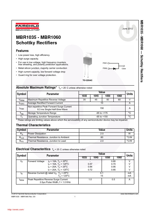
Note: 1. Repetitive rating: Pulse width limited by maximum junction temperature 2. L = 51mH, starting Tj = 25°C 3. L = 13µH, starting Tj = 25°C
Value
650 650 ±30 12.0 0.42 0.28 127 30 -0.3 to VSD 1.56 0.0125 +160 -25 to +85 -55 to +150
Characteristic KA5M0365RN, KA5L0365RN Maximum Drain Voltage Drain-Gate Voltage (RGS=1MΩ) Gate-Source (GND) Voltage Drain Current Pulsed (1) Continuous Drain Current (Ta=25°C) Continuous Drain Current (Ta=100°C) Single Pulsed Avalanche Energy (2) Maximum Supply Voltage Analog Input Voltage Range
Total Power Dissipation
Operating Junction Temperature. Operating Ambient Temperature. Storage Temperature Range.
Symbol
VD,MAX VDGR VGS IDM
ID ID EAS VCC,MAX VFB PD Derating TJ TA TSTG
VD,MAX VDGR VGS IDM
1035铝合金屈服强度-概述说明以及解释

1035铝合金屈服强度-概述说明以及解释1.引言1.1 概述:铝合金是一种常见的金属材料,其具有良好的强度和轻量化特性。
1035铝合金是铝合金中的一种常用材料,其具有较高的强度和良好的可加工性,被广泛应用于航空航天、汽车制造等领域。
屈服强度是衡量材料抗拉伸能力的重要指标,是材料在受力时首次出现塑性变形的应力值。
本文将重点探讨1035铝合金的屈服强度,分析其对材料性能和应用的影响,以期为相关领域的研究和生产提供参考。
通过对1035铝合金屈服强度的研究,有助于深入了解该材料的力学特性及其在工程领域中的应用前景,为铝合金材料的发展和利用提供科学依据。
1.2 文章结构:本文将分为三个主要部分进行讨论。
首先,将介绍1035铝合金的基本情况,包括其组成成分、物理性质等内容。
接着,将重点讨论铝合金屈服强度的重要性,分析其在工程领域中的作用和意义。
最后,将探讨影响铝合金屈服强度的因素,分析各种因素对屈服强度的影响程度,以便更好地了解如何提高铝合金的性能。
通过这三个部分的详细论述,读者将能够全面了解1035铝合金的屈服强度特性及其在实际应用中的重要性。
1.3 目的本文旨在研究1035铝合金的屈服强度,深入探讨其在工程领域中的重要性。
通过对铝合金屈服强度的影响因素进行分析,我们可以更好地了解这种材料的性能特点,为相关工程项目提供科学依据和技术支持。
同时,通过对屈服强度的研究,可以为今后铝合金材料的设计与生产提供指导,推动铝合金材料在不同领域的应用和发展。
通过本文的阐述,我们希望能够加深人们对1035铝合金屈服强度的认识,促进相关领域的学术交流与合作,推动材料科学的进步和发展。
2.正文2.1 1035铝合金简介1035铝合金是一种常见的铝合金材料,主要由铝、镍、铜和其他合金元素组成。
它具有优良的机械性能和耐腐蚀性能,被广泛应用于航空航天、汽车制造、建筑和电子等领域。
1035铝合金的化学成分为:铝(Al)98.51、镍(Ni)1.1、铜(Cu)0.8、锌(Zn)0.1等。
MBR1050;MBR1045;MBR1060;MBR1035;中文规格书,Datasheet资料
20 10 MBR1035-MBR1045
1
MBR1050-MBR1060
0.1
T A= 125ºC TA = 75º C
0.01
MBR1035-MBR1045
TA = 25º C
0.001 0
MBR1050-MBR1060
20
40
60
80 100 120
Percent of Rated Peak Reverse Voltage [%]
INDUCTIVE LOAD
2 .375" (9.00mm) LOAD
LENGTHS
0 0 25 50 75 100 125 150 175 Ambient Temperature [ºC]
Figure 1. Forward Current Derating Curve
Peak Forward Surge Current, IFSM [A]
0.5
Units
V V V V mA mA A
© 2012 Fairchild Semiconductor Corporation
MBR1035 - MBR1060 Rev. D0
1
/
MBR1035 - MBR1060 — Schottky Rectifie源自s354550
60
V
10
A
150
A
Tstg Storage Temperature Range
-65 to +175
°C
TJ Operating Junction Temperature
-65 to +150
°C
* These ratings are limiting values above which the serviceability of any semiconductor device may be impaired.
MTL4850 HART多路复用器安全手册说明书
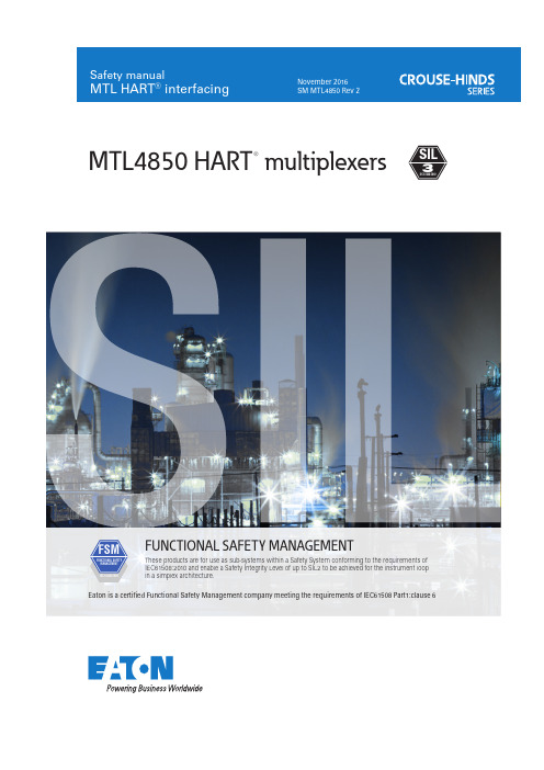
FSM FUNCTIONAL SAFETY MANAGEMENTThese products are for use as sub-systems within a Safety System conforming to the requirements ofIEC61508:2010 and enable a Safety Integrity Level of up to SIL2 to be achieved for the instrument loopin a simplex architecture.Eaton is a certified Functional Safety Management company meeting the requirements of IEC61508 Part1:clause 62SM MTL4850 Rev 2This manual supports the application of the products in functional safety related loops. It must be used in conjunction with other supporting documents to achieve correct installation, commissioning and operation. Specifically, the data sheet, instruction manual and applicable certificates for the particular product should be consulted, all of which are available on the MTL web site.In the interest of further technical developments, Eaton reserve the right to make design changes.Contents 1 Introduction 3 1.1 Application and function 3 1.2 Variant description 3 2 System configuration 4 2.1 Associated system components 5 3 Selection of product and implications 6 4 Assessment of functional safety 6 4.1 EMC 6 4.2 Environmental 6 5 Operation 7 6 Installation 7 7 Maintenance 7 8 Appendices 8 8.1 Appendix A: Summary of applicable standards and references 8 8.2 Appendix B: Certificate of functional safety 9MTL4850 HART® multiplexers SIL 33SM MTL4850 Rev 21 Introduction1.1 Application and functionThe MTL4850 HART multiplexer is used to create a two-way communications channel between numerous items of HART -enabled field equipment and a plant asset-monitoring/control system. Each multiplexer module can incorporate the HART data for up to 32 field channels into a single RS485 signal for onward linking to PC based instrument management software, thereby simplifying the wiring and reducing the cost-per-channel.The MTL4850 combines the functions of a HART modem, a power supply conditioner and all the necessarysignal-switching and addressing circuitry to multiplex the HART data. It provides a compact, convenient and cost-effective building block that can incorporated easily into both new and existing installations, especially as a partner for Eaton’s MTL4500 range of intrinsic safety interfaces. It is the modern version of our popular MTL4840 range and further simplifies the system.The MTL4850 multiplexer enables the user to gain access to valuable HART data provided by modern field devices in addition to the conventional 4/20mA loop signal provided by them. Many early process installation projects around the world did not take advantage of the data from HART -capable devices at start-up, so theMTL4850 offers a simple upgrade path to that data for asset management as well as the obvious live status and configuration information of the field devices.Most distributed control systems (DCS) now on the market incorporate the ability to pass HART communications information on the analogue input and output channels, but many safety systems (SIS and F&G) do not. Increasingly therefore, one of the main uses for the HART multiplexer is to provide HART communications for the field instruments connected to safety systems. In such implementations, it is crucial that the HART multiplexer does not interfere with the analogue loops of the safety system.1.2 Variant DescriptionThere are two versions of the product which are essentially the same but the modules differ in mounting in the following way:- MTL4850 is the general purpose Eaton product supplied in a blue enclosure- MTL4850-TR is supplied solely to Invensys (T riconex) in a black enclosure.Physically and electrically the products are the same but may contain different revision levels of the operating firmware. There is no difference between the products in regard to their application for functional safety.The functional safety assessment applies to MTL4850 with revision status 03 onwards and firmware version 1.02 onwards, as denoted on the product side label.MTL4850s on 64-channel HART Multiplexer PanelMTL4850 on 32-channel HART Termination Panel2 System configurationThe MTL4850 multiplexer may be used as part of an asset management system connecting to instrumentsignal loops that form part of a Safety Instrumented System up to SIL3. In general, the structure of such asystem is illustrated below.The HART multiplexer system provides access to the HART data in the field devices alongside the conventional4/20mA loops connecting them to the control or instrumentation system.“Capacitive isolation” is used to pick off the HART data from each ‘leg’ of the field signals. This ensures that theintegrity of each channel connection is unaffected by a component failure in another channel. As the multiplexerprovides a common bridge for the thirty-two channels that are connected to it, the importance of this signalseparation may be readily understood. This is particularly important when the multiplexer is associated withsignal loops that are feeding a safety shutdown system. It is critical that the integrity of the analogue loops forthe safety system is unaffected by any possible failures within the multiplexer.2.1 Associated System ComponentsThe connections onto the 4/20mA current signals that carry the HART data must be made through suitablewiring and terminations that preserve the separation and segregation of the idividual instrument loops.In process applications where the field signals use the intrinsic safety principle for explosion protection, theMTL4850 can be mounted together with the MTL4500 range of isolators on backplanes such as the CPH-SC16or the CPH-SC32. Alternatively, the isolators could be mounted on a backplane that is customised to suit aspecific instrument system, with the HART signals linked4SM MTL4850 Rev 25SM MTL4850 Rev 2to the multiplexer through multi-way cables. In this case, the MTL4850 would be mounted on an HMP-HM64 backplane which accepts HM64RIB20 multi-way ribbon cables from the backplanes.For applications that do not involve intrinsic safety, termination boards such as the HCU16 or HCU16AO provide the connection for the field and instrument system signals with the HM64RIB20 cables again linking to an HMP-HM64. In other instances the HTP-SC32 backplane offers a convenient mounting for the MTL4850 with connections available for 32 field and system signals.Refer to the instruction manual, INM4850, for details of all connection arrangements.3 Selection of product and implicationsThe transmission of HART data is not considered as part of the safety function and is excluded from this analysis, i.e. the HART functions of the MTL4850 are not to be used as a primary part of a safety system. An asset management software package, running on a PC and connected to the HART multiplexer, may be monitoring the health and performance of the field devices, or being used in a diagnostic role for example, but is not an integral part of the safety system.Protection against unintended changes to the configuration of the HART field devices must be employed either through the hardware of the devices using links or switches, or through firmware locks. Also the host management system running the communications to the HART multiplexers must include provision such as password protection to prevent re-configuration of the HART field devices by mistake.As the analogue signals carrying the HART data are part of a safety instrumented system, on-line changes to configuration, calibration or maintenance activity with the asset management system should be avoided. See also the need to ensure the integrity of the field signal connections explained in Section 5.Safety procedures must be put in place to ensure proper use of the configuration, calibration and maintenance facilities of the host software package with suitable verification of any changes made.Block diagram of MTL48504 Assessment of functional safetyThe MTL4850 HART multiplexer does not itself implement a safety function but may be applied alongsidemeasurement and control equipment that is providing a safety function.The multiplexer is designed to ensure that there is no effect on the analogue loops to which it is connected;multiple concurrent faults in the components that couple the MTL4850 to the analogue loops would have to bepresent before the isolation would be compromised.The design features, and the techniques/measures used to prevent systematic faults, make the MTL4850suitable for use in applications where the 4/20mA instrument loops, to which it is connected, are implementingsafety functions up to SIL3. Refer to the certificate for the method of assessment applied to avoid systematicfailures.The hardware assessment shows that MTL4850 HART Multiplexers:• have a hardware fault tolerance of 0• are classified as Type B devices• have no relevant internal diagnostic elements.**The random hardware failure rate of the MTL4850 at an ambient temperature of 60°C was determined asfollow:-The safe failure fraction is >90% (99%).It is assumed that the module is powered from a nominal 24V dc supply and at a maximum ambienttemperature of 45°C under normal conditions.There are no opportunities for external diagnostics to be applied to the MTL4850 HART multiplexer itself. Anymonitoring of the analogue loops to which it is connected must be conducted within the safety system.4.1 EMCThe MTL4850 modules are designed for operation in normal industrial electromagnetic environment but, tosupport good practice, modules should be mounted without being subjected to undue conducted or radiatedinterference, see Appendix A for applicable standards and levels.4.2 EnvironmentalThe MTL4850 modules operate over the temperature range from -40°C to +70°C, and at up to 95% non-condensing relative humidity.The modules are intended to be mounted in a normal industrial environment without excessive vibration,as specified for the MTL4850 and MTL45/5500 product ranges. See Appendix A for applicable standardsand levels.Continued reliable operation will be assured if the exposure to temperature and vibration are within the valuesgiven in the specification.** the multiplexer does in fact monitor the critical loop-connecting components, but it is not necessary forthese diagnostics to operate to achieve the SIL3 rating.6SM MTL4850 Rev 25 OperationRefer to the product instruction manual (INM4850) where details of the LED indications, in both normaloperation and under fault conditions, are given. A listing of the various messages recorded in the alarm/eventlogs, and their meanings, can also be found there.The design life for the MTL4850 product family is ten years, so provision should be made for replacement of theproducts within this expected lifetime.6 InstallationReference must be made to the relevant sections within the product instruction manual (INM4850) for theMTL4850 before installing these products.If the application involves intrinsic safety, then product instruction manuals INM4500 (MTL4500 range) orINM5500 (MTL5500 range) contain basic guides for the installation of the interface equipment to meet theserequirements.Provided that the installation requirements given in the manuals are followed then there are no additional factorsto meet the needs of applying the products for functional safety use.An important consideration for this equipment is that the analogue loops carrying the HART data form partof a safety system. All termination panels available from Eaton have been designed and manufactured with therequisite separation and segregation between channels to ensure the integrity of the signals that are connected tothe safety system.The connection and cabling employed for the loop signals must be implemented in accordance with local codesof practice and with the care necessary to preserve the sensitive nature of the signals. The selection, installation,inspection and protection of the cabling must be carried out with due regard for the routing, mechanical protectionagainst abrasion and any other damage that might cause interference with the safety signals.To guard against the effects of dust and water the modules should be mounted in an enclosure providing atleast IP54 protection degree, or the location of mounting should provide equivalent protection, such as inside anequipment cabinet.7 MaintenanceThe MTL4850 does not form part of a safety system and accordingly there is no requirement to conduct prooftesting of any safety function that it implements. For routine maintenance of the HART multiplexer system,refer to INM4850.To follow the guidelines pertaining to operation and maintenance of intrinsically safe equipment in a hazardousarea, yearly periodic audits of the installation are required by the various codes of practice.In addition, proof-testing of the loop operation to conform with functional safety requirements should be carriedout at the intervals determined by safety case assessment.Proof testing must be carried out according to the application requirements, but it is recommended that this becarried out at least once every three years.Note that there may also be specific requirements laid down in the E/E/PE operational maintenance procedurefor the complete installation.If an MTL4850 module is found to be faulty during commissioning or during the normal lifetime of the productthen such failures should be reported to the local MTL office. When appropriate, a Customer Incident Report(CIR) will be notified to enable the return of the unit to the factory for analysis. If the unit is within the warrantyperiod then a replacement unit will be sent.Consideration should be made of the normal lifetime for a device of this type which would be in the region of ten years.SM MTL4850 Rev 278 AppendiciesAppendix A: Summary of applicable standards and referencesThe annex lists together all standards referred to in the previous sections of this document:IEC61508:2010Functional safety of electrical/electronic/programmable electronic safety-related systems.Parts 1 and 2, as relevant.EN61131-2:2003Programmable controllers – Part 2: Equipment requirement and tests (EMC requirements).EN61326-1:2006E lectrical equipment for measurement, control and laboratory use – E MC requirements.(Criterion A).EN 61326-3-1:2008E lectrical equipment for measurement, control and laboratory use - E MC requirements -Part 3-1: Immunity requirements for safety-related systems and for equipment intended toperform safety-related functions (functional safety) - General industrial applications NE21 : 2007E lectromagnetic Compatibility of Industrial Process and Laboratory Control E quipment.(Criterion A).Reliability data for this analysis is taken from IEC TR 62380:2004 Reliability Data Handbook.Failure mode distributions are taken principally from IEC 62061:2005 Safety of Machinery.8SM MTL4850 Rev 29SM MTL4850 Rev 2 8.2 Appendix B: Certificate of functional safety10SM MTL4850 Rev 2SM MTL4850 Rev 21112SM MTL4850 Rev 2SM MTL4850 Rev 21314SM MTL4850 Rev 2This page is left intentionally blankSM MTL4850 Rev 215The given data is only intended as a product description and should not be regarded as a legal warranty of properties or guarantee. In the interest of further technical developments, we reserve the right to make design changes.EUROPE (EMEA): +44 (0)1582 723633 ********************THE AMERICAS: +1 800 835 7075 *********************ASIA-PACIFIC: +65 6645 9864 / 6645 9865 ***********************Eaton Electric Limited, Great Marlings, Butterfield, Luton Beds, LU2 8DL, UK.Tel: + 44 (0)1582 723633 Fax: + 44 (0)1582 422283E-mail:******************** © 2016 Eaton All Rights Reserved Publication No. SM MTL4850 Rev 2 151116November 2016AUSTRALIA MTL Instruments Pty Ltd, 10 Kent Road, Mascot, New South Wales, 2020, Australia Tel: +61 1300 308 374 Fax: +61 1300 308 463E-mail:*********************BeNeLux MTL Instruments BV Ambacht 6, 5301 KW Zaltbommel The Netherlands Tel: +31 (0) 418 570290 Fax: +31 (0) 418 541044E-mail:*********************CHINA Cooper Electric (Shanghai) Co. Ltd 955 Shengli Road, Heqing Industrial Park Pudong New Area, Shanghai 201201Tel: +86 21 2899 3817 Fax: +86 21 2899 3992E-mail:****************FRANCE MTL Instruments sarl,7 rue des Rosiéristes, 69410 Champagne au Mont d’Or France Tel: +33 (0)4 37 46 16 53 Fax: +33 (0)4 37 46 17 20E-mail:*******************GERMANY MTL Instruments GmbH, Heinrich-Hertz-Str. 12, 50170 Kerpen, Germany Tel: +49 (0)22 73 98 12 - 0 Fax: +49 (0)22 73 98 12 - 2 00E-mail:*******************INDIA MTL India, No.36, Nehru Street, Off Old Mahabalipuram Road Sholinganallur, Chennai - 600 119, India Tel: +91 (0) 44 24501660 /24501857 Fax: +91 (0) 44 24501463E-mail:***********************ITAL Y MTL Italia srl, Via San Bovio, 3, 20090 Segrate, Milano, ItalyTel: +39 02 959501 Fax: +39 02 95950759E-mail:******************JAPAN Cooper Crouse-Hinds Japan KK, MT Building 3F , 2-7-5 Shiba Daimon, Minato-ku,Tokyo, Japan 105-0012Tel: +81 (0)3 6430 3128 Fax: +81 (0)3 6430 3129E-mail:****************NORWA Y Norex AS Fekjan 7c, Postboks 147, N-1378 Nesbru, Norway Tel: +47 66 77 43 80 Fax: +47 66 84 55 33E-mail:*************RUSSIA Cooper Industries Russia LLC Elektrozavodskaya Str 33Building 4Moscow 107076, RussiaTel: +7 (495) 981 3770 Fax: +7 (495) 981 3771E-mail:*******************SINGAPORE Cooper Crouse-Hinds Pte Ltd No 2 Serangoon North Avenue 5, #06-01 Fu Yu Building Singapore 554911Tel: +65 6645 9864 / 6645 9865 Fax: +65 6 645 9865E-mail:***********************SOUTH KOREA Cooper Crouse-Hinds Korea 7F . Parkland Building 237-11 Nonhyun-dong Gangnam-gu,Seoul 135-546, South Korea.Tel: +82 6380 4805 Fax: +82 6380 4839E-mail:*******************UNITED ARAB EMIRATES Cooper Industries/Eaton Corporation Office 205/206, 2nd Floor SJ Towers, off. Old Airport Road, Abu Dhabi, United Arab Emirates Tel: +971 2 44 66 840 Fax: +971 2 44 66 841E-mail:*****************UNITED KINGDOM Eaton Electric Limited, Great Marlings, Butterfield, Luton Beds LU2 8DL Tel: +44 (0)1582 723633 Fax: +44 (0)1582 422283E-mail:********************AMERICAS Cooper Crouse-Hinds MTL Inc. 3413 N. Sam Houston Parkway W.Suite 200, Houston TX 77086, USA Tel: +1 281-571-8065 Fax: +1 281-571-8069E-mail:*********************。
Hartke 3500 Mosfet 使用手册说明书

I have a Hartke 3500 TA/MOSFET head that I bought new in the early 90's I'm gonna have to read the manual on line to get a solid grasp.vug.cloudo.pw/read? file=hartke+3500+transient+attack+manual. hartke ha3500 parts hartke 3500 mosfet schematic hartke systems transient. I tested the amp Hartke 2000 Mosfet Bass Amp. He$139.95. Kasino Natural bass amp powered up again, pdf Harley Benton GA15 g Hartke HA-3500 sch. Hartke Systems 3500 Mosfet 350 Watts Black. $. 200. Buy It Now Ampeg SVT-350H 350 Watt Classic Bass Amp Head w/ Owner's Manual. Ampeg SVT-350H. Download HARTKE HA5000 7000 service manual & repair info for electronics experts. Nejnovější verze legendárního baskytarového zesilovače střední třídy s výkonem 350 W, desetipásmovým ekvalizérem. Hartke HA3500/HA5500 OWNERS MANUAL. EUR 22.12. From United Hartke Systems 3500 Mosfet 350 Watts Black. EUR 200.03.
戴尼森水力控制器R5型号产品说明说明书

Publ.3–EN 2900–C (dig.)DENISON HYDRAULICSPressure Controls –Flanged TypeSeries R5with 3portsFEATURES,SYMBOLSYMBOLR5VR5V06pilot valveR5V08/10/12pilot valveY1(optional)Y1(optional)BAMExample:R5V Pressure Relief ValveFEATURESxIncrease Operating Satefy:Flange mounted valves as illustrated in this bulletin increase operating safety and reduce mounting costs.The R5range of flange bodied pressure controls enable the valves to be mounted directly on an SAE pump outlet flange,ensuring maximum pump protection against peak pressure and eliminating costly piping.xHigh Performance:R5valves are designed for a maximum adjustable pressure up to 350bar and a flow capacity ranging from 90l/min (3⁄4HH )to 600l/min (11⁄4HH and 11⁄2HH ).The pilot stage design reduces pressure overshoot and cracking flow to a minimum,thus reducing power and production losses during high pressure operation.xPrecise Control:With the DENISON combined Seat Valve and Pilot design,and the range of springs available,it is possible to achieve extremely precise pressure setting.xFast Response:The favourable poppet mass to area ratio is especially advanta-geous,as it enables such features as fast response,high accuracy and quiet,flutter free control.xWide Selection:In addition to the three port flange mount valve,the ordering code offers a wide range of control options for valves and accessories.DESCRIPTIONGENERALDESCRIPTIONDENISON Pressure Valves are pilot operated controls consisting of two or three valve sections,either a high flow,poppet type seat valve section controlled by the low flow,adjustable pilot mounted on top or in the case of the Proportional Pressure Relief Valve,the proportional section P2sandwiched between the pilot valve and the main body.Pressure setting is achieved by means of a knurled knob or,if a tamperproof setting is required,by an acorn nut with lead seal.A proportional pressure setting is achieved according to the current input by R5V (2)PRESSURE RELIEF VALVER5V pressure relief valves are used to limit the system pressure of a hydraulic system,in order to control the force exerted by a hydraulic actuator.The R5V valve may also be used to generate a pressure drop in a hydraulic circuit.Normally the pump is connected to Port A and the tank line to Port B.PRESSURE UNLOADING VALVEAccumulator system with Unloading Valve R5UR5U pressure unloading valves are used to unload a circuit at low pressure when a port signal (Port X1)is maintained at a pressure that is higher than that of the pilot section.A typical application for an R5U is to unload a pump that is connected to an accumulator circuit.Another use for the R5U is to unload the low pressure side of a double pump.In applications with an accumulator,it should be noted that the R5U and its accom-panying check valve should be mounted as close to the accumulator as possible.This will prevent that the …p,caused by long feed lines between the R5U and the accumulator,will reduce the selected 15or 28%pressure differential (prevention of switching oscillations).SEQUENCE VALVEThe R5S valve enables a hydraulic system to operate in a pressure sequence.After system pressure connected to Port A has reached a preadjusted value,fluid is allowed to pass through Port B to a secondary system.NOTEDENISON flange valves enable the realisation of complete control systems.In addition to the valves discussed in this publication,the following flange valves are also available:Publication–R5pressure valves with 2ports 3–EN 2850–F5C flow controls &R5A,R5P compensators 5–EN 4200–C5V check valves,direct operated 6–EN 4660–C5P check valves,direct &pilot operated 6–EN 4700–D5S seat valves with 2ports 7–EN 520–D5S seat valves with 3ports 7–EN 530setting pressuremin.operating pressureswitching difference 15%or 28%When the system pres-sure (in an accumulator for example)has fallen 15%or 28%below the pilot setting,the valve will close,and the pump flow will be restored to the hydraulic system.R5U..–..1/3=28%R5U..–..5=15%Note:The mentioned switching difference values are theoretical and can vary between 12...15%,respectively between 20...28%.TECHNICAL DATAGENERAL x Design Poppet typex Type of mounting Flanged according to SAE-61e.g.directly on a pump(R5V12according to SAE-62)x Port sizes3⁄4HH,1HH,11⁄4HH,11⁄2HH(only R5V,R5U)x Mounting position Optionalx Direction of flow A f Bx Ambient temperature range–20...+60h Cx Suitability for special Consult DENISONworking conditionsHYDRAULIC CHARACTERISTICS x Operating pressure–Inlet(Port A)...350bar R5*06/08...350bar R5V12(SAE62)...280bar R5*10...210bar R5U(V)12(SAE61)–Outlet(Port B)...30bar R5U,R5V...210,280,350bar R5S,R5U,R5VR5S:p at B<at A–Port X...210,280,350bar–Ports Y,Y1...30barx Pressure setting range–min≥3bar–max210,280,350barR5*06R5*08R5*10R5V,R5U123⁄4HH1HH11⁄4HH11⁄2HHx Max.flow90l/min300l/min600l/min600l/minx Nominal flow depends on pump deliveryx Fluid Mineral oil according to DIN51524/25(other fluids on request)x Contamination level Max.permissible contamination levelaccording to NAS1638Class8(Class9for15Micron and smaller)or ISO17/14x Fluid temperature range–18...+80h Cx Viscosity range10...650cSt;optimal30cStTYPE OF ACTUATOR x Manualx Rotation 3.75x360hx Operation torque72Ncmx Electric By solenoidx Nominal voltage Refer to ordering code page5x Permissible voltage difference+5% (10)x Max.coil temperature+180h C(temperature class H)x Type of current Alternating current(AC)or direct current(DC)x Input power31Wx Holding78VAx Inrush264VAx Relative operating period100%x Type of protection IP65x Electric proportional0...2.5A(Pilot stage P2)(refer to publication3–EN2200)ORDERING CODEomit for version without VV01&without P2Model NumberR5.............A1––––––SeriesR5V =Pressure Relief ValveR5U =Pressure Unloading Valve R5S =Sequence Valve Size 06=3⁄4HH08=1HH 10=11⁄4HH12=11⁄2HH (R5V,R5U only)Max.Pressure 3=210bar –SAE 61flange (R5V/R5U12)4=280bar –SAE 61flange (R5.10)5=350bar –SAE 61flange (R5.06/08)6=350bar –SAE62flange(R5V12only)BodyPorts X12),Y 11),M 2)3=SAE-4(7⁄16HH –20UNF)9=G 1⁄4HH1)Port Y1is only available at external PD (codes 4&6)from the pilot head 2)closed when suppliedPressure Setting Range1=...105bar (R5U:Pressure differential 28%)3=...210bar (R5U:Pressure differential 28%)5=...350bar (R5U:Pressure differential 15%)Type of Control1=Hand knob 32mm dia.2=Hand knob 50mm dia.(not for version with vent valve VV01or P2)3=Acorn nut with lead seal4=Adjusting device with key lock (key order no.700–70619–8)Pilot Connection2=Internal PD –internal PP (R5V)4=External PD –external PP*(R5U)5=Internal PD –external PP*(R5U)6=External PD –internal PP (R5V,R5S)*External pilot pressure connection on flange face (port X2)3-Way Vent Valve VV0109=with manual override Solenoid de-energized:open to tank 10=without manual override Solenoid energized:vent line blocked 11=with manual override Solenoid de-energized:vent line blocked 12=without manual overrideSolenoid energized:open to tankk kP2=Electric Proportional Pressure Control (12V DC only,R5V only)Solenoid Voltage and CurrentW01=115V /60Hz 1)G0R =12V W02=230V /60HzG0Q =24V DC W06=115V /50Hz ACG0H =48VW07=230V /50Hz1)R5V....P2=12V DC onlykkDesign LetterSeal Class1=NBR (Buna N)Standard 4=EPDM5=VITON `Modifications12345678 0123912345678910111213p-Q-CURVESP r e s s u r e (b a r )P r e s s u r e (b a r )Flow (l/min)Flow (l/min)R5V06R5V08n o m i n a l f l o wn o m i n a l f l o wMin.pressure setting ≥4bar(depending on flow and viscosity).Fluid 40cSt and 50h C ±0.5h C.P r e s s u r e (b a r )Flow (l/min)R5V10/12n o m i n a l f l o wUnloading Function free flow P -T R5U06Flow Q /l/minR5U08Flow Q /l/minR5U10/12Flow Q /l/minOverrided Pressure Relief Function R5U06Flow Q /l/minR5U08Flow Q /l/minR5U10/12Flow Q /l/minMin.pressure setting ≥4bar(depending on flow and viscosity).Fluid 40cSt and 50˜C ±0.5˜C.P r e s s u r e d r o p …p /b a rP r e s s u r e d r o p …p /b a rP r e s s u r e d r o p …p /b a rP r e s s u r e p /b a rP r e s s u r e p /b a rP r e s s u r e p /b a rn o m i n a l f l o wn o m i n a l f l o wn o m i n a l f l o wn o m i n a l f l o wn o m i n a l f l o w n o m i n a l f l o w3⁄8HH UNC x20lg.for R5U only(3.0dia.,only on R5U)external pilot pressure port available for usewith C5V check valvePorts Function Port sizes R5V R5U R5SA(2x)Pressure3⁄4HH(SAE-61)x x xB Tank2)3⁄4HH(SAE-61)x x xX1ext.pilot port1)G1⁄4HH or SAE-4xY1ext.drain G1⁄4HH or SAE-4x x xM Pressure gauge G1⁄4HH or SAE-4x x x1)closed when supplied2)secondary port on R5SNote:R5*06pressure controls are mounted directly on the”B”cartridge of DENISON vane pumpsand axial piston pumps PVT6.3⁄8HH UNC x23lg.for R5U only(3.0dia.,only on R5U)external pilot pressure port available for usewith C5V check valvePorts Function Port sizes R5V R5U R5SA(2x)Pressure1HH(SAE-61)x x xB Tank2)1HH(SAE-61)x x xX1ext.pilot port1)G1⁄4HH or SAE-4xY1ext.drain G1⁄4HH or SAE-4x x xM Pressure gauge G1⁄4HH or SAE-4x x x1)closed when supplied2)secondary port on R5SNote:R5*08pressure controls are mounted directly on the”C”cartridge of DENISON vane pumpsand axial piston pumps PVT10...29.7⁄16HH UNC x22lg.for R5U only(3.0dia.,only on R5U)external pilot pressure port available for usewith C5V check valvePorts Function Port sizes R5V R5U R5SA(2x)Pressure11⁄4HH(SAE-61)x x xB Tank2)11⁄4HH(SAE-61)x x xX1ext.pilot port1)G1⁄4HH or SAE-4xY1ext.drain G1⁄4HH or SAE-4x x xM Pressure gauge G1⁄4HH or SAE-4x x x1)closed when supplied2)secondary port on R5SNote:R5*10pressure controls are mounted directly on the”D”cartridge of DENISON vane pumps.R5V 12–R5U 12(11⁄2HH )Weight:8kgd 2x l 2for R5U only(3.0dia.,only on R5U)external pilot pressure port available for use with C5V check valvePorts Function Port sizes R5V R5U A (2x)Pressure 11⁄2HH (SAE-61/62)x x B Tank11⁄2HH (SAE-61/62)x x X1ext.pilot port 1)G 1⁄4HH or SAE-4x Y1ext.drain G 1⁄4HH or SAE-4x x MPressure gaugeG 1⁄4HH or SAE-4xx1)closed when suppliedNotes–R5*123–SAE 61mounted directly on the ”E”cartride of DENISON vane pumps.–R5V126–SAE 62mounted directly on the DENISON axial piston pumps series ”World-Cup”and ”Premier”.l 1l 2b 1d 1d 2R5*123SAE 6169.82735.713.51⁄2HH –13UNC R5V126SAE 6279.43336.5175⁄8HH –11UNCADDITIONAL TYPES OF CONTROLS,SYMBOLSADDITIONAL TYPES OF CONTROLSType of Control-Code 2Hand knob 50mm dia.(not for version with vent valve VV01or P2)Type of Control-code 3Acorn nut with lead sealType of Control-Code 4Adjusting device with key lock.Key must be ordered separately order-no.700–70619–8SYMBOLSInternal External Drain DrainPressure Relief Valve R5VPressure Unloading Valve R5USequence Valve R5SX1or X2X1or X2VERSION WITH VENT VALVE VV01Weight (VV01):1.7kgScrews for additional vent valve installation.4x 3⁄8HH –24UNF x 31⁄2HHlg.,order no.359–15340–0.Vent valveVV01Pilot valveY1Main valveManual overridePlug-in connector DIN 43650(supplied as standard)Solenoid can be turned:–through 90h intervals (AC)–in any position (DC)AC Ù149DC =160Note:Details for vent valve VV01see publication 3–EN 215.Symbols:R5*–Pressure Controls with Vent Valve VV01Pressure Relief ValvePressure Unloading ValveSequence ValveR5V R5U R5SCodeInternal External Internal External External DrainDrainDrainDrainDrain11or 1209or 10X1or X2X1or X2X1or X2X1or X2P ROP ORTIONAL P RESSURE RELIEF VALVE R5V...P2 Screws for additional proportional section installation4x3⁄8HH–24UNF x31⁄2HH lg.,Order No.359–15340–0.Pilot ValveProportionalsection P2(weight1.8kg)Main valve body (see pages7...10)Coil can be placed in any positionDrain lineOnly external from the pilothead(Y1).The pilot drain port must beconnected to a stable low pressuretank line.Pressure variations inthe drain port should be avoided.Distance required to removeplug-in connector.Plug-in connector suppliedas standard.Important:On initial start upand after long shut down periodsbleed air from thisplug. SymbolNote:See publication3–EN2200for information on Electrical Proportional Control Valve.For additional installation with pilot operated control valves please consult DENISON.SAE-FLANGESwith G-thread socket weldwith G-thread socket weldInlet flange (only forpipe mounting)available withUNC-threads onlyOutlet and tank port flangeInlet flange Outlet flange Tank port (without screws*)(without screws*)flange only for (with screws)pipe mounting Port sizes d 1Order No.Order No.Order No.l 1l 2b 1b 2b 3h 1h 2d 2l d 3l d 4l d 5G 3⁄4HH 1)3⁄4HHsocket weld S16–86520–0S16–86529–0S14–66933–0S16–86519–0S16–86528–0S14–66941–06747.63415.92222.2524016.51912–––10.53⁄8HHUNCG 1HH 1)1HH socket weld S16–86523–0S16–86532–0S14–66934–0S16–86522–0S16–86531–0S14–66942–07252.434202226.2584616.52414–––G 11⁄4HH 1)11⁄4HH socket weldS16–86526–0S16–86535–0S14–66935–0S16–86525–0S16–86534–0S14–66943–08058.739222430.2735417.52414–––12.57⁄16HHUNCG 11⁄2HH 1)11⁄2HH socket weldS26–52364–0S26–52215–0S14–66936–0S26–52366–0S26–52217–0S14–66944–09469.839242435.78260202616–––14.51⁄2HHUNCG 11⁄2HH 2)11⁄2HH socket weld464–01147–0464–01141–0464–01004–0464–01149–0464–01143–0464–01146–011279.450283036.594602517.55⁄8HHUNC1)SAE 612)SAE 62*see pages 15and 16for screwsExampleValves Group B R5*,F5C,C5P,D5S Valve Group AC5VPump or Motor Thigtening torque:28...40Nm for3⁄4HH valves 37...48Nm for1HH valves 48...62Nm for11⁄4HH valves 62...70Nm for11⁄2HH valvesInlet flange forpipe mounting(with threads for bolts)Socket weldQty.of valvesand group for UNC-Screws(12.9)Metric Screws(12.9) each stack l1l2Dimension Order No.Dimension Order No.1x A453⁄8HH–16x31⁄4HH358–16330–0M10x80361–11324–8 1x B603⁄8HH–16x33⁄4HH358–16350–0M10x95361–11354–83⁄4HH(1x A)+(1x B)10516...223⁄8HH–16x51⁄2HH358–16420–0M10x140361–11424–8SAE612x B1203⁄8HH–16x6HH358–16440–0M10x160700–70836–8 (1x A)+(2x B)1653⁄8HH–16x8HH358–16520–0M10x200700–70821–8 3x B1803⁄8HH–16x81⁄2HH358–16540–0M10x220361–11494–81x A453⁄8HH–16x31⁄4HH358–16330–0M10x80361–11324–81x B603⁄8HH–16x33⁄4HH358–16350–0M10x95361–11354–81HH(1x A)+(1x B)10518...243⁄8HH–16x53⁄4HH358–16430–0M10x140361–11424–8SAE612x B1203⁄8HH–16x61⁄4HH358–16450–0M10x160700–70836–8 (1x A)+(2x B)1653⁄8HH–16x8HH358–16520–0M10x200700–70821–8 3x B1803⁄8HH–16x81⁄2HH358–16540–0M10x220361–11494–81x A507⁄16HH–14x31⁄2HH358–18340–0M12x90361–12344–81x B757⁄16HH–14x41⁄2HH358–18380–0M12x120361–12404–811⁄4HH(1x A)+(1x B)12521...257⁄16HH–14x61⁄2HH358–18460–0M12x170361–12454–8SAE612x B1507⁄16HH–14x71⁄2HH358–18500–0M12x190361–12474–8 (1x A)+(2x B)2007⁄16HH–14x91⁄2HH358–18580–0M12x240361–12504–8 3x B2257⁄16HH–14x101⁄2HH358–18590–0M12x270361–12664–81x A501⁄2HH–13x33⁄4HH358–20350–0M12x90361–12344–81x B801⁄2HH–13x5HH358–20400–0M12x130361–12414–811⁄2HH(1x A)+(1x B)13025...271⁄2HH–13x63⁄4HH358–20470–0M12x170361–12454–8SAE612x B1601⁄2HH–13x8HH358–20520–0M12x200361–12484–8 (1x A)+(2x B)2101⁄2HH–13x10HH358–20600–0M12x250361–12674–8 3x B2401⁄2HH–13x111⁄4HH358–20650–0M12x290361–12684–8Nominal UNC-Screws (12.9)Metric Screws (12.9)Series Size l1l2Dimension Order No.Dimension Order No.R5V12–611/2HH 80305/8HH -11x 51/4HH 358-24410-0M16x 130361-14414-8C5V1211/2HH 50305/8HH -11x 4HH 358-24360-0M16x 100361-14364-8R5V12–6+C5V1211/2HH130305/8HH -11x 7HH358-24480-0M16x 180361-14464-8Pump or MotorSAE 62FlangeR5V12–6C5VThigtening torque:158...181NmThe product described is subject to continual development and the manufacturer reserves the right to change the specifications without notice.。
KA5H0380R中文资料

Characteristic Drain-source (GND) voltage (1)
Symbol VDSS
Drain-Gate voltage (RGS=1MΩ)
VDGR
Gate-source (GND) voltage Drain current pulsed (2) Single pulsed avalanche energy (3) Avalanche current (4)
Symbol BVDSS
IDSS
RDS(ON) gfs Ciss Coss Crss
td(on) tr
td(off) tf Qg
Qgs Qgd
Test condition
VGS=0V, ID=50µA VDS=Max., Rating, VGS=0V
VDS=0.8Max., Rating, VGS=0V, TC=125°C VGS=10V, ID=0.5A VDS=50V, ID=0.5A
Over current protection
IL(max)
UVLO SECTION
Start threshold voltage
Vth(H)
Minimum operating voltage
Vth(L)
TOTAL STANDBY CURRENT SECTION
Start current
IST
Operating supply current (control part only)
元器件交易网
KA5H0380R/KA5M0380R/KA5L0380R
SPS
Features
• Precision fixed operating frequency (100/67/50kHz) • Low start-up current(typ. 100uA) • Pulse by pulse current limiting • Over current protection • Over voltage protecton (Min. 25V) • Internal thermal shutdown function • Under voltage lockout • Internal high voltage sense FET • Auto-restart mode
- 1、下载文档前请自行甄别文档内容的完整性,平台不提供额外的编辑、内容补充、找答案等附加服务。
- 2、"仅部分预览"的文档,不可在线预览部分如存在完整性等问题,可反馈申请退款(可完整预览的文档不适用该条件!)。
- 3、如文档侵犯您的权益,请联系客服反馈,我们会尽快为您处理(人工客服工作时间:9:00-18:30)。
HAT1035R
Silicon P Channel Power MOS FET
High Speed Power Switching
REJ03G0845-0100
Rev.1.00
Apr.22,2005
Features
• Low on-resistance
• Capable of –4 V gate drive
• Low drive current
• High density mounting
Outline
Absolute Maximum Ratings
(Ta = 25°C)
Unit
Ratings
Item Symbol
Drain to Source voltage V DSS –150 V
Gate to Source voltage V GSS±15 V Drain current I D –0.25 A
Drain peak current I D(pulse)Note1 –1 A
Body-Drain diode reverse Drain current I DR –0.25 A Channel dissipation P ch Note2 1 W Channel dissipation P ch Note3 1.5 W Channel temperature Tch 150 °C
Storage temperature Tstg –55 to +150 °C
Notes: 1. PW ≤ 10 µs, duty cycle ≤ 1 %
2. 1 Drive operation : When using the glass epoxy board (FR4 40 x 40 x 1.6 mm)
3. 2 Drive operation : When using the glass epoxy board (FR4 40 x 40 x 1.6 mm)
Electrical Characteristics
(Ta = 25°C)
Item Symbol Min Typ Max Unit Test Conditions
Drain to Source breakdown
voltage
V (BR)DSS –150 — — V I D = –10 mA, V GS = 0 Gate to Source breakdown voltage V (BR)GSS ±15 — — V I G = ±100 µA, V DS = 0 Gate to Source leak current I GSS — — ±10 µA V GS = ±12 V, V DS = 0 Zero Gate voltage Drain current I DSS — — –5 µA V DS = –150 V, V GS = 0 Gate to Source cutoff voltage V GS(off) –1.0 — –2.0 V V DS = –10 V, I D = –1 mA
R DS(on) — 5.0 6.2 Ω I D = –0.25 A, V GS = –10 V Note4 R DS(on) — 6.0 7.5 Ω I D = –0.25 A, V GS = –4 V Note4
Static Drain to Source on state
resistance R DS(on) — 7.0 10.0 Ω
I D = –1 A, V GS = –5 V Note4 Forward transfer admittance |y fs | 0.29 0.45 — S I D = –0.25 A, V DS = –10 V Note4 Input capacitance Ciss — 92 — pF Output capacitance Coss — 37 — pF
Reverse transfer capacitance Crss — 10 — pF V DS = –10 V
V GS = 0 f = 1 MHz Turn-on delay time
t d(on) — 10 — ns Rise time
t r — 13 — ns
Turn-off delay time t d(off) — 22 — ns Fall time
t f — 15 — ns
V GS = –5 V, I D = –0.25 A,
V DD ≅ –30 V Body–Drain diode forward voltage V DF — –0.9 –1.4 V IF = –0.25 A, V GS = 0 Note4 Body–Drain diode reverse recovery time t rr — 80 — ns IF = –0.25 A, V GS = 0
diF/ dt = 50 A/µs
Notes: 4. Pulse test
Package Dimensions
Ordering Information
Part Name Quantity Shipping Container
HAT1035R-EL-E 2500
pcs. Taping
Note: For some grades, production may be terminated. Please contact the Renesas sales office to check the state of production before ordering the product.
RENESAS SALES OFFICES
Refer to "/en/network" for the latest and detailed information.
Renesas Technology America, Inc.
450 Holger Way, San Jose, CA 95134-1368, U.S.A
Tel: <1> (408) 382-7500, Fax: <1> (408) 382-7501
Renesas Technology Europe Limited
Dukes Meadow, Millboard Road, Bourne End, Buckinghamshire, SL8 5FH, U.K.
Tel: <44> (1628) 585-100, Fax: <44> (1628) 585-900
Renesas Technology Hong Kong Ltd.
7th Floor, North Tower, World Finance Centre, Harbour City, 1 Canton Road, Tsimshatsui, Kowloon, Hong Kong
Tel: <852> 2265-6688, Fax: <852> 2730-6071
Renesas Technology Taiwan Co., Ltd.
10th Floor, No.99, Fushing North Road, Taipei, Taiwan
Tel: <886> (2) 2715-2888, Fax: <886> (2) 2713-2999
Renesas Technology (Shanghai) Co., Ltd.
Unit2607 Ruijing Building, No.205 Maoming Road (S), Shanghai 200020, China
Tel: <86> (21) 6472-1001, Fax: <86> (21) 6415-2952
Renesas Technology Singapore Pte. Ltd.
1 Harbour Front Avenue, #06-10, Keppel Bay Tower, Singapore 098632
Tel: <65> 6213-0200, Fax: <65> 6278-8001。