IC Engine System-ansys
ANSYS Workbench 14.0 基础
ANSYS Workbench 14.0基础 作为一个全球知名的大型 CAE 分析软件,ANSYS 自 20 世纪 70 年代诞生以来,随着世 界信息技术和有限元理论的高速发展, 在各个领域得到了高度的评价和广泛的应用。
自ANSYS 7.0 开始,ANSYS 公司推出了 ANSYS 经典版(即 MAPDL )和 ANSYS Workbench 版。
本书 基于 ANSYS 14.0,较之前版 ANSYS 13.0,新版本在许多方面都得到了许多改进。
本章从 ANSYS Workbench 14.0 的概述开始,逐步讲解 ANSYS Workbench 14.0 结构设计流程。
本章 内容包括:l ANSYS Workbench 14.0 新功能特征概述l ANSYS Workbench 14.0 的工作流程l ANSYS Workbench 14.0 的文件管理l Mechanical APDL1.1 ANSYS Workbench 14.0 新功能概述[1] ANSYS Workbench 14.0 是一个集成框架,它整合现有的各种应用并将仿真过程结合在同 一界面下。
最新的 ANSYS Workbench 14.0 在 Workbench 13.0 的基础上更进一步提高和改进原 有的框架,尤其新版本更扩展了 ANSYS 系列产品的集成与多物理场的耦合应用,从总体看, ANSYS 14.0 的新优势主要体现在三个领域:扩展了工程应用、复杂系统的仿真、高性能计算 (HPC )的驱动创新。
1.1.1 扩展了工程应用较之 Workbench 13.0,ANSYS Workbench 14.0 更进一步扩大了在工程上的应用。
Ø 提高了 CAD 模型的处理和划分网格的功能。
复杂的 CAD 模型中常常包括多个零部件,作 CAE 分析时需要处理各零部件间的接触、 间隙等关系。
这是一个非常繁琐并且费时的过程!在ANSYS 14.0 中,利用装配体网格工具能 自动从 CAD 装配体中抽取相应的计算域,如流体域等,而且它能根据用户的要求,自动创建 Cutcell 的结构化直角网格(六面体网格单元)或者非结构化的四面体网格。
ANSYS菜单中英文对照
【Omega】参数对根据数量控制序列点【Sequence By N】选项这项是导引边末端和
末点之间的距离。
【Pattern】阵列特征 【Plane】平面 【Angle】旋转角 【Thickness】设置厚度
【Split】命令用于分割边线
【Line From Edges】边生成线体基于已有的2D和3D模型边界创建线体。
【Split Edges】分割线体分割线体边成段用比例特性控制分割位置如0.5等效于在
一半处分割。
【Cross Section】横截面横截面作为一种属性赋给线体这样就可以在有限元数值模
拟中定义梁的属性。
【Instance】草图援引草图援引用来复制源草图并将其加入到目标面中复制的草图和
源草图始终保持一
致,也就是说复制对象随着源对象的更新而更新。
【Freeze】冻结用冻结特征【Freeze】可以将所有的激活体转到冻结状态
【Collapse Environments】折叠结构树
【Collapse Models】折叠结构树中的Models项
【Named Selections】命名工具条 【Unit Conversion】单位转换工具 【MessagesMessages】信息窗口 【Simulation Wizard】向导
【Drag】拖曳 【Cut】剪切 【Copy】拷贝 【Paste】粘帖
粘贴命令
【End / Set Paste Handle】指定粘贴点位置
【End / Use Plane Origin as Handle】指定粘贴点在平面原点
【End / Use Default Paste Handle】将第一条线的起始点作为粘贴点
ANSYS学习-常见问题

目录1、线的单元属性(截面方向定义) (2)2、ANSYS中实体单元计算截面弯矩的方法(FSUM) (4)3、对称与反对称约束 (5)4、任意面施加任意方向任意变化的压力 (7)5、ansys荷载工况组合 (8)7、在ANSYS中用表面效应单元加任意方向的荷载 (10)8、Surf154 SFE (12)9、*VREAD 详细介绍 (23)10、几何刚度 (27)11、整数的输出方法与示例 (28)12、关于ANSYS的APDL中数据的输入输出格式 (29)13、LINK8温度荷载施加 (36)14、Ansys 进行荷载组合算例 (38)1、线的单元属性(截面方向定义)/blog/static/1752820372010102511326124/2、ANSYS中实体单元计算截面弯矩的方法(FSUM)/blog/static/1752820372010111393849327/?fromdm&fromSea rch&isFromSearchEngine=yes3、对称与反对称约束二、什么是对称或者反对称约束?1、对称边界条件在结构分析中是指:不能发生对称面外(out-of-plane)的移动(translations)和对称面内(in-plane)的旋转(rotations)。
这句话可以理解为:在结构中施加对称条件为指向边界的位移和绕边界的转动被固定。
例如,若对称面的法向为X,如果你在对称面上的节点上施加了对称边界条件,那么:1)不能发生对称面外的移动导致节点处的UX(法向位移)为0。
2)不能发生对称面内的旋转导致ROTZ,ROTY(绕两个切线方向的转角)也为0。
2、反对称边界条件在结构分析中是指:不能发生对称面(out-of-plane)的移动(translations)和对称面外(in-plane)的旋转(rotations)。
这句话可以理解为:在结构中施加反对称条件为平行边界的位移和绕垂直边界的转动被固定。
ANSYS助力海思推进产品创新

完善的研发技术平台、管理体系和人才培养体 系,专 ArgusTM)及 Rc寄生参 数提 取工具 (Empyrean RC—
注于 开发 全球 半 导体 产业 和 电子 信 息产 业所 需 的前 ExplorerTM)。 (来 自华 大九 天 )
沿技 术 和产 品 ,同时为 当地 人才 培 养提 供 了一 个优
式 互联 (片上 网络 ,或 NoC)。这 样 的环境 提 出了一 ANSYS)
个 重 大挑 战 ,涉 及 能 否确 保 处 理 器 得 到 了有 效 的使
用 、共享 数 据能 够保 持 一致 ,以及 能 否实 现传 输 数据
TowerJazz将 华 大 九天 AMS l C
互 联等 方 面 ,而片上 分 析则 大 幅简 化 了该任 务 。(来 自 UltraSoC)
新 思科 技 武汉 全球 研 发 中心座 落 于武汉 东湖新 决 方 案 包 括 电路 原 理 图 编辑 器 (Empyrean AetherT M
技术开发区 ,是新思科技在海外首次投资建设 的顶 sE)、电路仿真器 (Empyrean ALPSTM)、版图编辑器
级 研发 中心 ,预计 2019年 建成 投用 。它拥 有 先进 和 (Empyrean AetherTM LE)、物 理 验证 工 具 (Empyrean
秀平 台 。 (来 自新 思科 技 )
联华 电子和 Ava l anche合作 技术
ANSYS助 力海思推进产 品创 新
开 发 MRAM及泛 采 用 ANSYS的 电源 完 整 性 和 可 靠 性 分 析解 决 方案 ,全 球 领先 的半 导 体企 业 、华为 全 资子 公 司海 思 科技 正 在积 极推 进 新一 代移 动 、网络 、人工 智能 和 5G产 品 的创 新 升级 。
ansys Workbench;菜单选项中英文对照
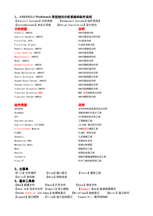
1、ANSYS12.1 Workbench界面相关分析系统和组件说明【Analysis Systems】分析系统【Component Systems】组件系统】【CustomSystems】自定义系统【Design Exploration】设计优化分析类型说明Electric (ANSYS) ANSYS电场分析Explicit Dynamics (ANSYS) ANSYS显式动力学分析Fluid Flow (CFX) CFX流体分析Fluid Flow (Fluent) FLUENT流体分析Hamonic Response (ANSYS) ANSYS谐响应分析Linear Buckling (ANSYS) ANSYS线性屈曲Magnetostatic (ANSYS) ANSYS静磁场分析Modal (ANSYS) ANSYS模态分析Random Vibration (ANSYS) ANSYS随机振动分析Response Spectrum (ANSYS) ANSYS响应谱分析Shape Optimization (ANSYS) ANSYS形状优化分析Static Structural (ANSYS) ANSYS结构静力分析Steady-State Thermal (ANSYS) ANSYS稳态热分析Thermal-Electric (ANSYS) ANSYS热电耦合分析Transient Structural(ANSYS) ANSYS结构瞬态分析Transient Structural(MBD)MBD 多体结构动力分析Transient Thermal(ANSYS) ANSYS瞬态热分析组件类型说明AUTODYN AUTODYN非线性显式动力分析BladeGen 涡轮机械叶片设计工具CFX CFX高端流体分析工具Engineering Data 工程数据工具Explicit Dynamic(LS-DYNA)LS-DYNA 显式动力分析Finite Element Modeler FEM有限元模型工具FLUNET FLUNET 流体分析Geometry 几何建模工具Mechanical APDL 机械APDL命令Mechanical Model机械分析模型Mesh 网格划分工具Results 结果后处理工具TurboGrid 涡轮叶栅通道网格生成工具Vista TF 叶片二维性能评估工具2、主菜单【File】文件操作【View】窗口显示【Tools】提供工具【Units】单位制【Help】帮助信息3、基本工具条【New】新建文件【Open】打开文件【Save】保存文件【Save As】另存为文件【Import】导入模型【Compact Mode】紧凑视图模式【Shade Exterior and Edges】轮廓线显示【Wireframe】线框显示【Ruler】显示标尺【Legend】显示图例【Triad】显示坐标图示 Expand All:展开结构树【Collapse Environments】折叠结构树【Collapse Models】折叠结构树中的Models项【Named Selections】命名工具条【Unit Conversion】单位转换工具【Messages:Messages】信息窗口【Simulation Wizard】向导【Graphics Annotations】注释【Section Planes】截面信息窗口【Reset Layout】重新安排界面4、建模【Geometry】几何模型【New Geometry】新建几何模型【Details View】详细信息窗口【Graphics】图形窗口:显示当前模型状态【Extrude】拉伸【Revolve】旋转【Sweep】扫掠【Skin/Loft】蒙皮【Thin/Surface】抽壳:【Thin】创建薄壁实体【Surface】创建简化壳【Face to Remove】删除面:所选面将从体中删除。
ANSYS 2019R2重新定义新一代工程仿真解决方案

ANSYS 2019R2重新定义新一代工程仿真解决方案随着工程仿真技术的不断发展,ANSYS 作为业内领先的工程仿真软件提供商,始终以技术创新为导向,不断推出更新升级版本,为工程界提供更加先进的仿真解决方案。
2019 年,ANSYS 推出了全新的 2019R2 版本,重新定义了新一代工程仿真解决方案,为用户带来更多前所未有的功能和性能体验。
ANSYS 2019R2 版本在模拟虚拟现实、工程仿真、材料科学和电子集成设计领域进行了全面的升级优化,为用户提供了更加全面和先进的解决方案。
无论是在复杂结构的设计优化、材料性能分析,还是在电子产品的热管理和电磁兼容性等方面,ANSYS 2019R2 都提供了全面而精准的仿真能力,助力用户更好地完成工程设计和优化任务。
在模拟虚拟现实方面,ANSYS 2019R2 版本增强了与第三方虚拟现实平台的集成能力,用户可以更加轻松地将仿真数据导入到虚拟现实系统中进行可视化展示和交互操作,提升了工程设计过程的效率和可视化体验。
ANSYS 2019R2 版本加强了对多物理场耦合仿真的支持,包括流固耦合、热-流场耦合等多种物理场的耦合仿真分析,为用户提供更加全面的仿真解决方案。
在工程仿真领域,ANSYS 2019R2 版本加入了新的拓展模块,如声学仿真分析、疲劳分析等,为用户提供了更广泛的仿真能力。
ANSYS 2019R2 版本还提供了更加强大和高效的优化算法和工具,加速了工程设计的优化过程,减少了设计迭代的时间和成本。
在电子集成设计领域,ANSYS 2019R2 版本加强了对电磁兼容性和热管理的仿真分析能力,用户可以更加准确地分析电子产品的电磁性能和热性能,优化产品设计和性能,提升产品的品质和可靠性。
在性能提升方面,ANSYS 2019R2 版本对软件的性能和稳定性进行了全面优化,用户可以更加流畅地进行仿真分析和数据处理,节省时间和精力。
ANSYS 2019R2 版本还加强了与云计算和大数据平台的集成能力,用户可以更加便捷地进行分布式计算和大规模数据处理,提高了仿真分析的效率和灵活性。
IC Engine System-ansys

Can be used to setup a customized case Can be used to perform custom post‐processing
Workbench ICE System
ANSYS Workbench
CAD Automatically Generated Reports
Fluent R12
IC engine report, IC specific vaporization laws, coherent flamelet model, EGR, ignition UDF
Fluent R14
Aftertreatment: selective catalytic reduction, catalytic converter light off Combustion: G‐eqn Multiphase: SSD
Different Meshing Configurations
4 layers between valve and valve‐seat at fully‐ closed position of valve
one layer in the gap at fully‐closed position of valve
IC Engine Results
Automatic Report Generation
IC Enginห้องสมุดไป่ตู้ System: Introduction
• IC Engine System
• A new Workbench Analysis System similar to Fluid‐Flow(Fluent) or Fluid‐Flow (CFX) Analysis Systems • Reduces the setup time of ICE cold flow and port flow problems from many hours to few minutes • First released ANSYS R14 • Supported on Windows and Linux platforms • Standard feature included with ANSYS FLUENT
[IT计算机]ANSYS在IC封装行业的应用
![[IT计算机]ANSYS在IC封装行业的应用](https://img.taocdn.com/s3/m/5957ec064531b90d6c85ec3a87c24028915f8534.png)
ANSYS In IC Packaging27/10/01 ANSYS♋Introduction of Electronic Packaging♋Simulation with ANSYS in IC Packaging ♋Summary27/10/01 ANSYS♋Introduction of Electronic Packaging ☝Types of electronic packaging☝Function of electronic packaging☝Tendency of electronic packaging☝Importance of package design27/10/01 ANSYS27/10/01 ANSYSTypes of electronic packaging27/10/01 ANSYSFunction of electronic packaging(a) signal distribution(c) heat dissipation (b) power distribution (d) package protection27/10/01 ANSYSTendency of electronic packaging27/10/01 ANSYSImportance of electronic packaging Package Design & Characterization FlowchartTotal Product Qualification Through Simulation!• Confidence In Product Performance Before Manufacturing –Guarantee Customer Wins!• Reduce Costs & Optimize Designs–Eliminate Product Redesigns–Exploit Materials & Configurations–Reduce Reliability Testing• Reduce Time -to-Market–Guarantee Manufacturability–Guarantee Product Qualification27/10/01 ANSYS♋Simulation with ANSYS in IC Packaging ☝Mechanical AnalysisStress/Strain SimulationWarpage SimulationDie Crack & Crack Propagation ☝Thermal AnalysisThermal Resistance Calculation ☝Moisture AnalysisDelamination & Popcorn27/10/01 ANSYSStress/Strain Analysis Mechanical Simulation Model of MaterialsLinearMaterialNonlinear Material Rate-independent plasticityRate-dependent plasticityCreepNonlinear elasticityViscoelasticityHyperelasticityConcreteSwellingElasticMaterial27/10/01 ANSYSANSYS in IC Packaging27/10/01 ANSYSSYSStress/Strain during thermal cycling &prediction of fatigue life with Coffin-Manson EquationStress/Strain AnalysisMechanical Simulation(a)(b)CrackCrackCrack positions in solder joints for packages (a) without underfill and (b) with underfillSchematic illustration of the flip chip packages-550C1250C200C21T e m p r a t u r eTemperature histories in thermal cycling27/10/01 ANSYS(a)(b)Finite element meshes for flip chip package in 2D (a)and a local view including the solder joint (b)Geometry building of flip chip package in 3DStress/Strain AnalysisMechanical Simulation27/10/01 ANSYS(a) (b)Plastic strain distribution in solder joints after 125 C dwell for Btype package (a) without underfill (b) with underfillXY ZStress/Strain AnalysisMechanical Simulation27/10/01 ANSYS(a) (b)Microstructure coarsening after 348 thermal cycling test forflip chip packages with underfill(a) experimental result (b) strain distribution from simulationStress/Strain AnalysisMechanical Simulation27/10/01 ANSYSdiagonal lineStress distribution for whole flip chip package cooling from 125︒C to 5︒CStress/Strain AnalysisMechanical SimulationXAADeformation of chip at low temperature holdingANSYS in IC Packaging27/10/01 ANSYSSYSStress/Strain AnalysisMechanical SimulationDelamination and Crack Propagation-----Fracture Mechanical Method in ANSYSThree Basic Modes of FractureOpening Mode (KI )Shearing Mode (K II )Tearing Mode (K III )Crack tipCrack length 0.8mmFinite element model of 2D cracked structureDistribution of equivalent viscoplastic strainaround crack tip(at start of –55o C dwell, a=1.6mm)27/10/01 ANSYSANSYS in IC Packaging27/10/01 ANSYSSYSThermal AnalysisHeat Dissipation SimulationThermal Resistance:θjc : thermal resistance between semiconductor elementjunction and package surface (o C/W)θca : thermal resistance between package surface andambient atmosphere (o C/W)θja : thermal resistance between semiconductor elementjunction and ambient atmosphere (o C/W)Definition of thermal resistance (QFP)aja j T P T +⨯=θOptimal thermal design with ANSYS!PackageSemiconductor Element T jT c T a θca θjcθjaBoardRelationship of air film coefficient and temperature27/10/01 ANSYS27/10/01 ANSYSAg EpoxyMoldingCu SolderCu SolderdCu2dCu 0.5dCu Thickness (mm)0.25400.50800.1270T max (oC)149.516143.897151.656 T (o C)99.51693.897101.656Thermal Resistance (oC/W)33.17231.29933.885Comparison of thermal resistance with different Cu thicknessThermal AnalysisHeat Dissipation Simulation27/10/01 ANSYSThermal distribution of CuThermal distribution at die backThermal distribution of deviceThermal AnalysisHeat Dissipation Simulation27/10/01 ANSYSThermal AnalysisHeat Dissipation SimulationFLOTRAN CFD in ANSYSMesh of car with CFD analysis27/10/01 ANSYSThermal AnalysisHeat Dissipation SimulationTemperature stream lines in cooling periodFLOTRAN CFD in ANSYS27/10/01 ANSYSMoisture diffusion procedureMoisture AnalysisMoisture Analysisdelamination due tomoistureC-SAM images of delamination at the chip/underfill interface offlip chip at 85o C/85%RH27/10/01 ANSYSMoisture Analysispopcorn due to moistureMechanism of package cracking27/10/01 ANSYS27/10/01 ANSYSMoisture Analysisadhesive strength decreased due to moistureComparison of adhesive strength at MC/Cu interface betweendry sample and wet sample27/10/01 ANSYSMoisture Analysisadhesive strength simulation at interface during reflowTypical temperature curve foreutectic SnPb solder during reflowprocessThermal stress simulation at 200o CMoisture AnalysisJEDEC standards for moisture testingSOAK REQUIREMENTSLEVEL FLOOR LIFEStandard Accelerated Equivalent1TIME CONDITIONS TIME(hours)CONDITIONSTIME(hours)CONDITIONS1Unlimited≤30o C/85%RH168≤85o C/85%RH2 1 year≤30o C/60%RH168≤85o C/60%RH2a 4 weeks≤30o C/60%RH6962≤30o C/60%RH120≤60o C/60%RH 3168 hours≤30o C/60%RH1922≤30o C/60%RH40≤60o C/60%RH 472 hours≤30o C/60%RH962≤30o C/60%RH20≤60o C/60%RH 548 hours≤30o C/60%RH722≤30o C/60%RH15≤60o C/60%RH 5a24 hours≤30o C/60%RH482≤30o C/60%RH10≤60o C/60%RH6Time on Label(TOL)≤30o C/60%RH TOL≤30o C/60%RHMoisture Sensitivity LevelsLoading conditions as JEDEC standards in ANSYS27/10/01 ANSYSANSYS in IC Packaging27/10/01 ANSYSSYSSummary♋Simulation is very important step with ANSYS in IC packaging design.♋Reasonable material model can be built by corresponding element types in ANSYS, including elastic material, viscoelastic material, viscoplastic material and other nonlinear material models ♋Stress/Strain analysis can be used to predict the fatigue life of solder joints from ANSYS simulation results.♋The calculation of thermal resistance from thermal distribution of devices is very helpful for optimal thermal design.♋Moisture diffusion simulation and popcorn prediction in ANSYS。
- 1、下载文档前请自行甄别文档内容的完整性,平台不提供额外的编辑、内容补充、找答案等附加服务。
- 2、"仅部分预览"的文档,不可在线预览部分如存在完整性等问题,可反馈申请退款(可完整预览的文档不适用该条件!)。
- 3、如文档侵犯您的权益,请联系客服反馈,我们会尽快为您处理(人工客服工作时间:9:00-18:30)。
Different Meshing Configurations
Inflation layer in the port
No Inflation layer in the port
Different Meshing Configurations
Decomposition in combustion chamber region for layered mesh
2009
2010
Fluent R13
2011
2012
Fluent R14.5
Sprays: spray angle vs. crank angle, cone injection sector meshes Mesh related: 2nd order in time MDM, contact detection, cutcelg Configurations
4 layers between valve and valve‐seat at fully‐ closed position of valve
one layer in the gap at fully‐closed position of valve
– – – – – Reads the valve and piston profile Create various dynamic mesh zones Create interfaces required for dynamic mesh setup Set up the dynamic mesh parameters Create all the required events, to model opening and closing of valves, and corresponding modifications in solver settings and under‐relaxations factors Set up the required models Set up the default boundary conditions and material Set up the default monitors Initialize and patch the solution
Geometry Preparation
Geometry Inputs
Basic Geometry Information
Valve geometry and profile information Optional Animation Inputs Advanced Options
Mesh Generation
Fluent R12
IC engine report, IC specific vaporization laws, coherent flamelet model, EGR, ignition UDF
Fluent R14
Aftertreatment: selective catalytic reduction, catalytic converter light off Combustion: G‐eqn Multiphase: SSD
• • •
Demo Future Plans Summary
Among internal combustion engine CFD applications, in‐cylinder flow is of central importance in determining engine efficiency and emissions
Scope of IC Engine System
• Automated geometry preparation and mesh generation for all 4 stroke engines – any number of valves – all standard shapes of piston at the given crank angle • Automated case setup for “cold‐flow” and “port‐flow” type simulations based on the best practices – including mesh motion • User hooks for complex physics setup, e.g. spray injection, combustion simulation • Automated report generation
– Gather the required user input needed to accurately model the user’s specific engine. WB‐ICE tool – Prepare the Geometry and Mesh: operations semi‐ Perform following automatically suitable for modeling the • Decompose the geometry in a manner motion of valves and piston and then create the mesh Geometry Solver Setup • Manually decomposing Decomposition the geometry and meshing takes between 6 hours and a couple of days, depending on experience Mesh Creation • Learning curve for manual geometry decomposition and meshing is very steep!! – Set‐up and run the simulation: • Setting up the case requires knowledge of models like dynamic mesh, reacting flows, discrete‐phase etc. – Analyze and interpret results
IC Engine Results
Automatic Report Generation
IC Engine System: Introduction
• IC Engine System
• A new Workbench Analysis System similar to Fluid‐Flow(Fluent) or Fluid‐Flow (CFX) Analysis Systems • Reduces the setup time of ICE cold flow and port flow problems from many hours to few minutes • First released ANSYS R14 • Supported on Windows and Linux platforms • Standard feature included with ANSYS FLUENT
Can be used to setup a customized case Can be used to perform custom post‐processing
Workbench ICE System
ANSYS Workbench
CAD Automatically Generated Reports
IC Engine System Properties
For engines with piston pin offset
These IC inputs can be defined as Parameters
User can hook boundary condition profiles
No decomposition in chamber region for engines with very little squish at TDC or pistons with valve recess regions
Solver Setup
• IC Engine System will automatically setup the problem
DesignModeler ANSYS Meshing Single Mesh
Multiple Meshes (keyframes) (new R14.5)
FLUENT Solver CFD Post
Cold Flow Simulation Setup Using IC Engine System:
Cold Flow Simulation using IC Engine System
• Automatic preparation of geometry for meshing • Automatic meshing including inflation layers and layering zones • Automatic setup dynamic zones, events, and solver settings • HTML report creation • Reduces the turnaround time (CAD import to CFD setup) to less than an hour
Key‐frame mesh, mesh smoothing, DPM and combustion extensions: multiple spark model, Veynante ECFM for LES, KHRT break‐up model,
* The Workbench IC Engine system uses a well‐tested subset of Fluent features