GB162HNGBANUB-V00中文资料
常用电力电缆规格型号之欧阳与创编

聚氯乙烯绝缘聚氯乙烯护套电力电缆1、用途:本产品适用于交流50HZ,额定电压0.6/1KV 的线路中,供输配电能之用。
2、产品标准:GB12706·2-91额定电压35KV及以下铜芯、铝芯塑料绝缘电力电缆、聚氯乙烯绝缘电力电缆3、使用特性:1)电缆导体的最高额定温度为70℃。
2)短路时(最长持续时间不超过5S)电缆导体的最高温度不超过160℃。
3)敷设电缆时的环境温度应不低于0℃,最小弯曲半径应不小于电缆外径的10倍。
4、型号、名称和使用范围6、生产范围交联聚乙烯绝缘电力电缆1、产品用途:本产品适用于额定电压(U0/U)为3.6/6至26/35KV电力线路,供输配电能之用。
2、产品标准:GB12706-91额定电压35KV及以下铜芯,铝芯塑料绝缘电力电缆。
3、产品使用特性:(1)电缆在环境温度不低于0℃条件下敷设时,无须预先加温。
电缆的敷设落差不受限制。
(2)电缆线芯长期允许工作温度不得超过下列规定:外护层是聚氯乙烯套的电缆为90℃;外护层是聚乙烯套的电缆为80℃。
(3)线芯短路时(最长持续5S)温度不得超过250℃(4)电缆敷设时的最小弯曲半径规定如下:单芯电缆:20(d+D)±5%;三芯电缆:15(d+D)±5%。
式中:D为电缆的实际外径,d为导体的实际外径。
4、产品型号、名称及使用范围注:一根或二根单芯电缆不允许敷设在铁质管道中。
5、生产范围聚氯乙烯绝缘电线1、用途:本产品适用于交流额定电压450/750V及以下的动力装置的固定敷设。
2、产品标准:GB5023、2-85《额定电压450/750V及以下聚氯乙烯绝缘电缆(电线)固定敷设用电缆(电线)》3、产品使用特性:1)额定电压U0/U分为450/750V 和300/500V。
2)电缆的长期允许工作温度:BV-105型……应不超过105℃;其他型号……应不超过70℃。
3)电缆的敷设温度应不低于0℃;4)电缆的允许弯曲半径为:电缆外径(D)小于25mm者……应不小于4D;电缆外径(D)为25mm及以上者……应不小于6D4、电缆型号、名称及使用范围5、生产范围聚氯乙烯绝缘软电线1、用途:本产品适用于交流额定电压450/750V及以下的家用电器、小型电动工具、仪器仪表及动力照明等装置的连接。
垫片基础知识培训

法兰密封面型式和代号(GB/T9112-2000) 密封面型式 代号 FF 平面 RF 突面 MF M 凹凸面 凸面 F 凹面 TG T 榫槽面 榫面 G 槽面 RJ 环连接面
-
垫片尺寸标准编号
公称压力或压力等级 公称通径
垫片材料代号 (外环、金属 带、填充带、 内环) 垫片型式代号
垫片材料代号(GB/T 4622.1-2003)
0Cr25Ni20
5
热陶瓷 纤维
5
00Cr17Ni14 Mo2
4
在英、美等国家中,尽管目前在有关标准中已列入了公称压力的概念,但 实际使用中仍采用英制单位Class。由于公称压力和压力等级的温度基准 不同,因此两者没有严格的对应关系。
标记示例1: 公称通径150mm,公称压力4.0MPa(40bar)的带内外环型 缠绕垫,外环材料为低碳钢非金属带材料为柔性石墨,垫片 尺寸标准GB/T4622.2; 其标记为:缠绕垫 D 1222-DN150-PN40 GB/T4622.2 标记示例2: 公称通径100mm,公称压力2.0MPa(Class150)的带外环型 缠绕垫,外环材料为0Cr18Ni9,金属带材料为0Cr18Ni9,非 金属带材料为柔性石墨,垫片尺寸标准HG20631; 其标记为:缠绕垫 C 1220 100—2.0 2220 HG20631
法兰的分类
6、法兰盖
法兰盖也叫盲法兰,它是与管路上的法 兰相配合使用的,因此使用时,法兰盖的密 封面和公称压力应与管道上选用的法兰完全 一致。
法兰面的形式
突面法兰 (代号RF) 全平面法兰 (代号FF)
法兰面的形式
凹凸面法兰(代号MFM) 榫槽面法兰(代号TG)
法兰面的形式
凹平面法兰(代号FG) 梯形面法兰(代号RJ)
Belden 23AWG 纤维厚胶防腐乳乏氧膜腔双膜电缆说明书

1855P Coax - Sub-Miniature Plenum
Minimum Return Loss:
Start Freq. (MHz) Stop Freq. (MHz) Min. RL (dB)
5.000
1600.000
23.000
1600.000
1
Insulation Insulation Material:
Insulation Material
Dia. (in.)
Gas-injected FEP - Foam Florinated Ethylene Propylene 0.102
Outer Shield Outer Shield Material:
23 AWG solid .023" bare copper conductor, gas-injected foam FEP insulation, Duofoil® (100% coverage) plus a tinned copper braid shield (95% coverage), flexible Flamarrest® jacket.
Electrical Characteristics (Overall)
Nom. Characteristic Impedance: Impedance (Ohm) 75
Nom. Inductance: Inductance (µH/ft) 0.300
Nom. Capacitance Conductor to Shield: Capacitance (pF/ft) 16.300
Other Electrical Characteristic 1: Other Electrical Characteristic 2:
GB中常用标准件标准
GB中常用标准GB中常用标准螺栓和螺柱六角头螺栓GB/T27-1988六角头铰制孔用螺栓A级GB/T27-1988六角头铰制孔用螺栓B级GB/T31.1-1988六角头螺杆带孔螺栓-A级和B级GB/T31.2-1988A型六角头螺杆带孔螺栓-细杆-B级GB/T31.2-1988B型六角头螺杆带孔螺栓-细杆-B级GB/T5780-2000六角头螺栓C级GB/T5781-2000六角头螺栓-全螺纹-C级GB/T5782-2000六角头螺栓GB/T5783-2000六角头螺栓-全螺纹GB/T5784-1986六角头螺栓-细杆-B级GB/T5785-2000六角头螺栓-细牙GB/T5786-2000型六角头螺栓-细牙-全螺纹其它螺栓GB/T8-1988方头螺栓C级GB/T 10-1988沉头方颈螺栓GB/T 11-1988沉头带榫螺栓GB/T 37-1988T形槽用螺栓GB/T 798-1988活节螺栓GB/T 799-1988地脚螺栓GB/T 800-1988沉头双榫螺栓GB/T 794-1993加强半圆头方颈螺栓A型GB/T 794-1993加强半圆头方颈螺栓B型双头螺柱GB/T897-1988双头螺柱B型GB/T 898-1988双头螺柱B型GB/T 899-1988双头螺柱B型GB/T 900-1988双头螺柱B型GB/T 901-1988等长双头螺柱-B级GB/T 953-1988等长双头螺柱-C级螺母六角螺母1型六角螺母C级(GB41-86)GB56-1988六角厚螺母GB808-1988小六角特扁细牙螺母GB/T6170-2000(1型六角螺母)GB/T6171-2000(1型六角螺母-细牙)GB/T6172.1-2000六角薄螺母GB/T6173-2000六角薄螺母-细牙GB/T6174-2000六角薄螺母-无倒角GB/T6175-2000(2型六角螺母)GB/T6176-2000(2型六角螺母-细牙)六角锁紧螺母GB/T6184-2000(1型全金属六角锁紧螺母)GB/T6185.1-2000(2型全金属六角锁紧螺母)GB/T6185.2-2000(2型全金属六角锁紧螺母-细牙) GB/T6186-2000(2型全金属六角锁紧螺母-9级)六角开槽螺母GB6179-1986(1型六角开槽螺母-C级)GB6180-1986(2型六角开槽螺母-A级和B级)GB6181-1986六角开槽薄螺母-A和B级GB9457-1988(1型六角开槽螺母)GB9458-1988(2型六角开槽螺母-细牙-A级和B级) GB9459-1988六角开槽薄螺母GB6178-1986(1型六角开槽螺母-A和B级)圆螺母GB810-1988小圆螺母GB817-1988带槽圆螺母GB812-1988圆螺母滚花高螺母GB806-1988滚花高螺母GB807-1988滚花薄螺母其它螺母GB923-1988盖形螺母GB39-1988方螺母-C级螺钉十字槽螺钉GB/T818-2000十字槽盘头螺钉H型GB/T818-2000十字槽盘头螺钉Z型GB/T819.1-2000十字槽沉头螺钉第一部分H型GB/T819.1-2000十字槽沉头螺钉第一部分Z型GB/T820-2000十字槽半沉头螺钉H型GB/T820-2000十字槽半沉头螺钉Z型。
垫片的M、Y值GB

M值
2 3 2 3 2.2 2 2 2 4.4 2.5 1.75 1
Y值(MPa)
6.9-13.8 19.31 6.9-13.8 19.31 15.86 10.35 8.28 12.41 17.24 24.14 19.66 1.38
备注
1
0.1
3 3 3 3 1 2.5 2.2 2 3(液)4.5(汽) 3 2.3 3.8 3.75 5.5 6.5
名称
柔性石墨板材垫片 金属增强石墨板材垫片 柔性石墨板材垫片 金属增强石墨板材垫片 进口膨化PTFE板材垫片 白色增强四氟板材垫片 蓝色增加四氟板材垫片 乳白色增强四氟板材垫片 棕色增强四氟板材垫片 纯四氟包覆垫片 纯四氟板材垫片 红色橡胶板材垫片 丁腈橡胶板材垫片 氟橡胶板材垫片 丁苯橡胶板材垫片 氯丁橡胶板材垫片 三元乙丙橡胶板材垫片 硅橡胶板材垫片 海泡石增强橡胶板材垫片 通用型芳纶纤维板材垫片 碳纤维加强纤维板材垫片 蒸汽用纤维加强板材垫片 植物纤维板材垫片 英克镍加强石墨带状垫片 硅橡胶带状垫片 进口膨化PTFE带状垫片 缠绕垫片 波形活压垫片 金属包覆垫片 金属齿形复合垫片 波形复合垫片 波齿复合垫片 椭圆垫、八角垫
10.35 15.17 15.17 15.17 1.38 18.62 17.24 13.8 33.8-68.97 55.17 16.55 64.83 60 124.14 179.31
参考 参考ຫໍສະໝຸດ 316/304+石墨 316/304+四氟
软铁 不锈钢
金属平垫片
4-6.5
0.417-1.23
3mm
AIG垫片的M、Y值
型号
AIG38 AIG 39 AIG OEM138 AIG OEM139 AIG 184IM AIG 156IM AIG 157IM AIG 158IM AIG 159IM AIG 37 AIG 36 AIG 100 AIG 141 AIG 142 AIG 143 AIG 144 AIG 146 AIG 147 AIG HPS AIG 300IM AIG 310IM AIG 350IM AIG 140 AIG 165 AIG 175 AIG 185IM AIG SU/V型 AIG 250/252/254 AIG 32 AIG 33 AIG 31 AIG 34 AIG 30
金属缠绕垫

金属缠绕垫分四种规格,为A,B,C,D型A型为基本型,即不带环,完全由金属带和非金属带缠绕起来的,适用于榫槽面。
B型为内环型,适用于MFM面C型为外环型,适用于RF面,但是压力低于6.3MPaD型为内外环型,适用于RF面缠绕垫的型号为4位阿拉伯数字首位代表外环材料,第二位代表金属带材料,第三位代表材料代号,第四位代表内环材料0:无2:3041:特制石棉纸0:无1:低碳钢3:3162:柔性石墨1:低碳钢2:3044:316L3:F42:3044:非特制石棉纸3:3164:316L举个例子垫片为0220型,就是A型垫,不带环,金属带为304,非金属为石墨0211则是B型垫,带内环,金属带为301,非金属带为柔性石墨我们常说金属石墨缠绕垫或金属石棉缠绕垫,一般是X22X型和X21X型,X根据法兰面定如:D1221带碳钢内外环304+石墨缠绕垫片D1222带碳钢外环不锈钢内环304+石墨缠绕垫片D1232带碳钢外环不锈钢内环316+石墨缠绕垫片(按照技术上讲,如果缠绕部分钢带用316的话,内环至少也要是316不锈钢的)中国人民共和国机械行业标准管路法兰用缠绕式垫片本标准适用于公称压力PN为2.5—10.0Mpa的管路法兰用缠绕式垫片3、垫片形式和代号3.1垫片形式按图1及彪1的规定a。
基本型(A型)b.带内环型(B型)c.带外环型(C型)d.带内外环型(D型)表2公称通径DN 公称压力PN 4.06.310.16.0MPa内环内径D1缠绕片内径D2缠绕片外径D3缠绕片厚度T内环厚度T110142434 3.2及4.52及31518293920253650253243573238516540456175505773876576951098089106120100108129149125133155175150159183203200219239259250273292312300325343363350377395421400426447473450480497523500530549575表3公称通径DN内环内径D1缠绕垫内径D2缠绕垫外径D3外环外径D4缠绕垫厚度T外环厚度T12.5MPa 4.0MPa 1014243646463.2及4.52及3151829405151202536506161253243577171323851678282404558749292505773911071076576891091271278089102122142142100108127147167167125133152174195195150159179201225225200219228254285290250273282310340351300325334362400416350377387417456476400426436468516544450480491527566569500530541577619628600630642678731741表1垫片形式代号适应密封面型式基本型A 榫槽面带内环型B 凹凸面带外环型C 凸面带内外型D4、垫片尺寸4.1A 型B 型按表2尺寸4.2C 型D 型按表3尺寸□□□□□□□□垫片尺寸标准号(GB/T4622)公称压力公称通径内环填充带金属带外环垫片型式代号C型—外环型D型—内外型标记示例公称直径是DN100,公称压力是PN25,带内外环型,外环材质不锈钢,304不锈钢钢带,石墨填充带,304不锈钢内环,其标记为:DN100PN25D2222HG20610-1997常用型式:A0220三、垫片型式和材料代号外环材料金属带材料非金属带材料内环材料名称代号名称代号名称代号名称代号无00Gr18Ni92特制石棉纸1无0低碳钢10Gr17Ni12Mo23柔性石墨带2低碳钢1 0Gr18Ni9200Gr17Ni14Mo24聚四氟乙烯30Gr18Ni92特质非石棉纸40Gr17Ni12Mo2300Gr17Ni14Mo24。
缠绕垫标准中数字的含义
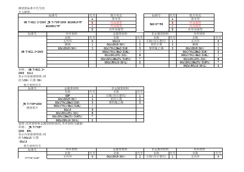
内环、外环、金属带材料 名称 代号 1 0Cr13 0Cr18Ni9(304)、 2 SH3407-96 1Cr18Ni9Ti(321) 管法兰用缠绕式垫片 3 0Cr17Ni12Mo2(316) 00Cr19Ni10(304L)、 4 00Cr17Ni14Mo2(316L) 6 Q235A 材质顺序表示:内环/金属带/非金属带/外环 举例: SH3407-96 D1216 表示内外加强缠绕垫:材质为0Cr13/304/石墨/碳钢标准号 SH340来自-96代号 A B C D
代号 1 2 3 4 6 7 8
非金属带材料 名称 代号 石棉(用石墨代) 1 柔性石墨 2 聚四氟乙烯 3
垫片形式 基本型 外加强型 内加强型 内外加强型 内环材料 名称 无内环 碳钢 0Cr18Ni9(304) 0Cr17Ni12Mo2(316) 00Cr17Ni14Mo2(316L) 0Cr18Ni10Ti(321) 0Cr18Ni12Mo2Ti(316Ti) 00Cr19Ni10(304L)
代号 2 3 4
非金属带材料 名称 代号 石棉(用石墨代) 1 柔性石墨 2 聚四氟乙烯 3
内环材料 名称 无内环 碳钢 0Cr18Ni9(304) 0Cr17Ni12Mo2(316) 00Cr17Ni14Mo2(316L)
代号 0 1 2 3 4
举例: HG20631-97 1220 表示外加强缠绕垫:材质为碳钢/304/石墨 垫片材料代号 标准号
代号 0 1 2 3 4
举例: HG20610-97 1212 表示内外加强缠绕垫:材质为碳钢/304/石墨/304
垫片材料代号 标准号 HG20631-97 钢制管法兰缠绕式垫 片(Class系列)
外环材料 名称 无外环 碳钢 0Cr18Ni9(304)
PE导电袋技术参数中英文对照
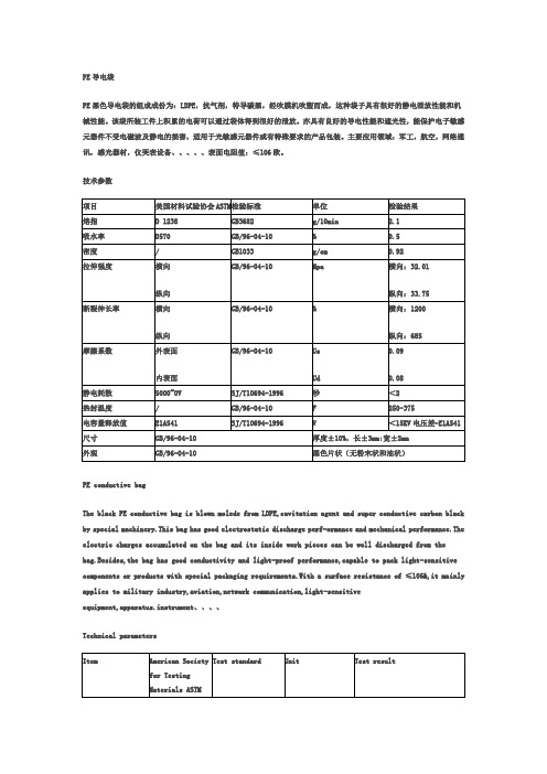
PE导电袋PE黑色导电袋的组成成份为:LDPE,抗气剂,特导碳黑,经吹膜机吹塑而成,这种袋子具有很好的静电泄放性能和机械性能。
该袋所装工件上积累的电荷可以通过袋体得到很好的泄放。
亦具有良好的导电性能和遮光性,能保护电子敏感元器件不受电磁波及静电的损害,适用于光敏感元器件或有特殊要求的产品包装。
主要应用领域:军工,航空,网络通讯,感光器材,仪哭表设备、、、、、表面电阻值:≤106欧。
技术参数PE conductive bagThe black PE conductive bag is blown molede from LDPE,cavitation agent and super conductive carbon black by special machinery.This bag has good electrostatic discharge perf-ormance and mechanical performance.The electric charges accumulated on the bag and its inside work pieces can be well discharged from the bag.Besides,the bag has good conductivity and light-proof performance,capable to pack light-sensitive components or products with special packaging requirements.With a surface resistance of ≤106&,it ma inly applies to military industry,aviation,network communication,light-sensitiveequipment,apparatus.instrument、、、、Technical parameters。
- 1、下载文档前请自行甄别文档内容的完整性,平台不提供额外的编辑、内容补充、找答案等附加服务。
- 2、"仅部分预览"的文档,不可在线预览部分如存在完整性等问题,可反馈申请退款(可完整预览的文档不适用该条件!)。
- 3、如文档侵犯您的权益,请联系客服反馈,我们会尽快为您处理(人工客服工作时间:9:00-18:30)。
JEWEL HILL ELECTRONIC CO.,LTDJEWEL HILL ELECTRONIC CO.,LTD.SPECIFICATIONS FORLCD MODULEModule No. GB162HOffice Address: Rm. 518,5/F., 101 Shangbu Industrial District,HuaqiangNorthRoad, Shenzhen, ChinaTEL : (86)-755-83362489 83617492FAX: (86)-755-83286396 83365871E-mail: sales@jhlcd@Website: TABLE OF CONTENTSLCM NUMBER SYSTEM (2)1. GENERAL DESCRIPTION (3)2. FEATURES (3)3. MECHANICAL SPECIFICATION (3)4. MECHANICAL DIMENSION (4)5. MAXIMUM RATINGS (5)6. ELECTRICAL CHARACTERISTICS (5)7. MODULE FUNCTION DESCRIPTION (6)8. ELECTRO-OPTICAL CHARACTERISTICS (12)9. RELIABILITY (16)10. PRECAUTIONS FOR USING LCD MODULES (17)11. USING LCD MODULES (19)12. REVISION HISTORY (21)SAMPLE APPROVED REPORT (22)LCM Number SystemNUMBER OF CHAR. PER LINE F: FSTN; X: OTHER VERSION NUMBER: V00~V99IC TYPE:VIEWING DIRECTION:TEMPERATURE RANGE:BACKLIGHT TYPE:SERIAL NUMBER: A~ZGRAPHIC MODULEs: NUMBER OF COMMONs GRAPHIC MODULEs:NUMBER OF SEGMENTs COB & SMT LCMBACKLIGHT COLOR:CHARACTER MODULEs:CHARACTER MODULEs: NUMBER OF LINE G: REFLECTIVE,NONE BACKLIGHT A: TRANSFLECTIVE, EL BACKLIGHT B: TRANSMISSIVE, EL BACKLIGHT C: TRANSFLECTIVE, LED BACKLIGHT D: TRANSMISSIVE, LED BACKLIGHT E: TRANSFLECTIVE, CCFL BACKLIGHT F: TRANSMISSIVE, CCFL BACKLIGHT A: AMBER; B: BLUE; Y: YELLOW-GREEN R: RED; W: WHITE; O: THER COLOR N: NORMAL TEMPERATURE RANGE U: UPPER(12:00); D: DOWN(6:00)L: LEFT(9:00); R: RIGHT(3:00);A: BONDING IC, WITH CONTROLLER B: BONDING IC, WITHOUT CONTROLLER C: SMT IC, WITH CONTROLLER D: SMT IC, WITHOUT CONTROLLER O: OTHER TYPEW: BLACK-WHITE; O: OTHER G: GRAY; Y: YELLOW-GREEN; B: BLUE; LCD COLOR MODE:N: TN; H: HTN; S: STN LCD TYPE:S: SUPER WIDE TEMPERATURE RANGE W: WIDE TEMPERATURE RANGEM: MIDDLE TEMPERATURE RANGE1. GENERAL DESCRIPTIONThe GB162H is a 16C x 2L Character LCD module. It has a STN panel composed of 80 segments and16 commons. The LCM can be easily accessed by micro-controller via parallel interface.2. FEATURESTransflective and positiveDisplay ModeSTN(Yellow - Green) moduleDisplay Format Character 16C x 2LInput Data 8/4-bit parallel data input from MPUMultiplexing Ratio 1/16 DutyBiasBias 1/5Viewing Direction 6 O’clockBacklight LED3. MECHANICAL SPECIFICATIONItem Specifications Unit Dimensional outline 84.0 x 44.0 x 12.7(max) mmResolution 80segs x 16coms dotsActive area 56.21(W) x 11.5(H) mmChar. pitch 3.55(W) x 5.94(H) mmChar. size 2.96(W) x 5.56(L) mmDots pitch 0.6 (W)×0.7(H) mmDots size 0. 56(W)×0.66(H) mm4. MECHANICAL DIMENSION5. MAXIMUM RATINGSItem Symbol Min Max Unit NoteV DD - V ss -0.3 7.0 V Supply voltage V LCD -0.3 13.0 V Input Voltage V IN -0.3 V DD +0.3 VOperating temperature T OPR 0 +50 Storage temperature T STR -10 +60Humidity --- --- 90 %RH6. ELECTRICAL CHARACTERISTICSItem SymbolCondition Min. Typ. Max. UnitSupply Voltage Logic V DD---2.73.3 5.5 VH level V IH 0.8V DD --- V DDInput VoltageL levelV IL --- V SS --- 0.2V DDVCurrent Consumption(LCD DRIVER)I DDV DD =3.3V;V LCD =4.7V,T amb =25 ;--- --- 5.0 mALCD Driving Voltage V LCDBias=1/5V LCD =V DD -V 5--- 4.7 --- VCurrent Consumption (With LED BackLight)I LEDV LED =4.2V,T amb =25 ;--- --- 300 mA7. MODULE FUNCTION DESCRIPTION7.1. PIN DESCRIPTIONPin No. Symbol Description1 VSSPower supply for Ground S2 VDDPower supply for positive3 VOVLCD negative voltage regulation4 RSData/Command register selection; “H”: Data; “L”: Command5 R/WRead/write selection signal,”H”: Read;”L”: Write6 ERead/write Enable signal input pin7 DB08 DB19 DB210 DB38-bit bi-directional data bus11 DB412 DB513 DB614 DB715 LEDAPower supply voltage for backlight positive(4.2V)16 LEDKPower supply voltage for backlight negative(0V)7.2 TIMING CHARACTERISTICS1. SYSTEM BUS READ/WRITE CHARACTERISTIC7.3 APPLICATION OF LCMReference circuitCircuit Block Diagram7.4 TABLE OF COMMAND7.5 CHARACTER GENERATOR ROM8. ELECTRO-OPTICAL CHARACTERISTICSItem Symbol Condition Temp Min Typ. Max UnitsNote4.6 4.9 ---25 4.4 4.7 5.0 LCD driving voltageV LCD = = 050 4.2 4.5 4.8 V NOTE1Rise Time (Tr) --- --- -- Decay Time (Tf)0 --- ---- --- Rise Time (Tr) --- 225 340Decay Time (Tf) 25 --- 240 360Rise Time (Tr) --- --- -- Response TimeDecay Time (Tf)= = 0 50 --- --- --msec NOTE2Contrast Ratio Cr= = 0 255 10 --- --- NOTE4Viewing AngleRange( = 0°)(6”) = 90°(3”) =180°(12”) =270°(9”)(25 ) CR ≥245 35 20 35DegNOTE3z For panel only․Electro-Optical Characteristics Measuring Equipment(DMS501)SystemIllumination (D65)․Note 1. Definition of Driving Voltage( Vlcd) :․Note 3. Definition of Viewing Angle and :․Note 4. Definition of Contrast ratio( CR) :Brightness of Non-selected Segment (B2)Brightness of Selected Segment (B1)CR =V,maxCR,maxDriving VoltageB r i gh t n e s s (%)Brightness Curve forSelected Segment0%=90 =270Viewing Direction 6 O’clock DirectionNormal :9. RELIABILITY9.1. MTBFThe LCD module shall be designed to meet a minimum MTBF value of 50000 hours with normal. (25°C in the room without sunlight)9.2. TESTSNO. ITEM CONDITION CRITERION1 High Temperature Operating 50 120Hrs2 Low Temperature Operating 0 120Hrs3High Temperature/Humidity Non-Operating50 ,90%RH ,120 Hrs4 High TemperatureNon-Operating60 120Hrs5 Low TemperatureNon-Operating-10 120Hrs6 Temperature CyclingNon-Operating0 (30Min )↔ 50 (30Min)10 CYCLESNo Defect OfOperational Function InRoom Temperature AreAllowable.IDD of LCM inPre-and post-test shouldfollow specificationNotes: Judgments should be mode after exposure in room temperature for two hours.10. PRECAUTIONS FOR USING LCD MODULES10.1. HANDLING PRECAUTIONS(1) The display panel is made of glass. Do not subject it to a mechanical shock or impact by droppingit.(2) If the display panel is damaged and the liquid crystal substance leaks out, be sure not to get any inyour mouth. If the substance contacts your skin or clothes, wash it off using soap and water.(3) Do not apply excessive force to the display surface or the adjoining areas since this may cause thecolor tone to vary.(4) The polarizer covering the display surface of the LCD module is soft and easily scratched. Handlethis polarizer carefully.(5) If the display surface becomes contaminated, breathe on the surface and gently wipe it with a softdry cloth. If it is heavily contaminated, moisten a cloth with one of the following solvents: - Isopropyl alcohol- Ethyl alcohol(6) Solvents other than those above mentioned may damage the polarizer.Especially, do not use the following:- Water- Ketone- Aromatic solvents(7) Extra care to minimize corrosion of the electrode. Water droplets, moisture condensation or acurrent flow in a high-humidity environment accelerates corrosion of the electrode.(8) Install the LCD Module by using the mounting holes. When mounting the LCD Module, makesure it is free of twisting, warping and distortion. In particular, do not forcibly pull or bend the I/Ocable or the backlight cable.(9) Do not attempt to disassemble or process the LCD Module.(10) NC terminal should be open. Do not connect anything.(11) If the logic circuit power is off, do not apply the input signals.(12) To prevent destruction of the elements by static electricity, be careful to maintain an optimumwork environment.- Be sure to ground the body when handling he LCD Module.- Tools required for assembling, such as soldering irons, must be properly grounded.-To reduce the amount of static electricity generated, do not conduct assembling and other workunder dry conditions.-The LCD Module is coated with a film to protect the display surface. Exercise care when peeling off this protective film since static electricity may be generated.10.2. STORAGE CONDITIONSWhen storing, avoid the LCD module to be exposed to direct sunlight of fluorescent lamps. For stability, to keep it away form high temperature and high humidity environment (The best condition is : 23±5°C, 45±20%RH). ESD protection is necessary for long-term storage also.10.3. OTHERSLiquid crystals solidify under low temperature (below the storage temperature range) leading to defective orientation or the generation of air bubbles (black or white). Air bubbles may also be generated if the module is subject to a low temperature.If the LCD Module have been operating for a long time showing the same display patterns the display patterns may remain on the screen as ghost images and a slight contrast irregularity may also appear.A normal operating status can be recovered by suspending use for some time. It should be noted that this phenomenon does not adversely affect performance reliability.To minimize the performance degradation of the LCD Module resulting from destruction caused by static electricity etc. exercise care to avoid holding the following sections when handling the modules.- Exposed area of the printed circuit board.- Terminal electrode sections.11. Using LCD modules11.1 LIQUID CRYSTAL DISPLAY MODULESLCD is composed of glass and polarizer. Pay attention to the following items when handling.(1) Please keep the temperature within specified range for use and storage. Polarization degradation,bubble generation or polarizer peel-off may occur with high temperature and high humidity.(2) Do not touch, push or rub the exposed polarizers with anything harder than a HB pencil lead (glass,tweezers, etc).(3) N-hexane is recommended for cleaning the adhesives used to attach front/rear polarizers andreflectors made of organic substances, which will be damaged by chemicals such as acetone, toluene, toluene, ethanol and isopropyl alcohol.(4) When the display surface becomes dusty, wipe gently with absorbent cotton or other soft materiallike chamois soaked in petroleum ether. Do not scrub hard to avoid damaging the display surface.(5) Wipe off saliva or water drops immediately, contact with water over a long period of time maycause deformation or color fading.(6) Avoid contacting oil and fats.(7) Condensation on the surface and contact with terminals due to cold will damage, stain orpolarizers. After products are tested at low temperature they must be warmed up in a container before coming is contacting with room temperature air.(8) Do not put or attach anything on the display area to avoid leaving marks on.(9) Do not touch the display with bare hands. This will stain the display area and degrade insulationbetween terminals (some cosmetics are determinate to the polarizers).(10)As glass is fragile, it tends to become or chipped during handling especially on the edges. Pleaseavoid dropping or jarring.11.2 INSTALLING LCD MODULEAttend to the following items when installing the LCM.(1) Cover the surface with a transparent protective plate to protect the polarizer and LC cell.(2) When assembling the LCM into other equipment, the spacer to the bit between the LCM and thefitting plate should have enough height to avoid causing stress to the module surface, refer to the individual specifications for measurements. The measurement tolerance should be ±0.1mm.11.3 ELECTRO-STATIC DISCHARGE CONTROLSince this module uses a CMOS LSI, the same careful attention should be paid for electrostatic discharge as for an ordinary CMOS IC.(1) Make certain that you are grounded when handing LCM.(2) Before removing LCM from its packing case or incorporating it into a set, be sure the module andyour body have the same electric potential.(3) When soldering the terminal of LCM, make certain the AC power source for the soldering irondoes not leak.(4) When using an electric screwdriver to attach LCM, the screwdriver should be of groundpotentiality to minimize as much as possible any transmission of electromagnetic waves produced sparks coming from the commutator of the motor.(5) As far as possible, make the electric potential of your work clothes and that of the workbenches tothe ground potential.(6) To reduce the generation of electro-static discharge, be careful that the air in the work is not toodried. A relative humidity of 50%-60% is recommended.11.4 PRECAUTIONS FOR OPERATION(1) Viewing angle varies with the change of liquid crystal driving voltage (Vo). Adjust Vo to showthe best contrast.(2) Driving the LCD in the voltage above the limit will shorten its lifetime.(3) Response time is greatly delayed at temperature below the operating temperature range. However,this does not mean the LCD will be out of the order. It will recover when it returns to the specified temperature range.(4) If the display area is pushed hard during operation, the display will become abnormal. However, itwill return to normal if it is turned off and then on.(5) Condensation on terminals can cause an electrochemical reaction disrupting the terminal circuit.Therefore, this product must be used and stored within the specified condition of 23±5°C, 45±20%RH.(6) When turning the power on, input each signal after the positive/negative voltage becomes stable.11.5 SAFETY(1) It is recommended to crush damaged or unnecessary LCDs into pieces and wash them off withsolvents such as acetone and ethanol, which should later be burned.(2) If any liquid leaks out of a damaged glass cell and comes in contact with the hands, wash offthoroughly with soap and water.12. REVISION HISTORYrecord Date Version Reviseversion 06-06-101.0 OriginalSAMPLE APPROVED REPORT。