SPEC_CLAS070VA01_V0.0_100512[1]
Ultracapacitor - Battery Energy Storage System for Hybrid Electric Vehicles

ii
ACKNOWLEDGEMENT
This research was supported by a research grant from DaimlerChrysler, AG and by NASA Grant NAG3-2790 under subcontract from Bowling Green State University.
APPENDIX II: SYSTEM SCHEMATICS...................................................................... 69
ivபைடு நூலகம்
List of Figures
Figure 1.1 Figure 1.2 Figure 4.1 Figure 4.2 Figure 5.1 Figure 5.2 Figure 6.1 Figure 6.2 Figure 7.1 Figure 7.2 Figure 7.3 Figure 7.4 Figure 7.5 Figure 7.6 Figure 7.7 Figure 7.8 Figure 7.9 Figure 7.10 Figure 8.1 Figure 8.2 Figure 8.3 Figure 8.4 Figure 8.5 Figure 8.6 Figure 8.7 Figure 8.8 Figure 8.9 Figure 8.10 Hybrid Fuel Cell – Ultracapacitor ESS Hybrid Battery-Ultracapacitor ESS Equivalent circuit of a parallel battery/UC Hybrid UC-Battery Simulated Discharge Current Waveforms Proposed Hybrid Battery-UC ESS Simulated Constant Power Pulse First Battery Charging Method Second Battery Charging Method The Proposed Performance Characterization Method ICE Efficiency Map and The Power Split Rule Battery Charging and Routine Message Transmission Algorithm Analog Interface and Vehicle Simulation Algorithm Secondary Microcontroller Algorithms PC Monitor Software screen shot ABC-150 ROS Algorithm Battery Voltage Sense signal conditioning IR2118 Based Relay Driver Circuit LEM Current Sensor signal manipulation circuit Results for 300A / 5 sec. test currents Results for 300A / 8 sec. test currents Results for the Idle-Stop Test StampPlot Pro screen capture Simulator results to demonstrate battery charging and 52 53 54 55 56 57 Simulator results to demonstrate Power Assist Mode Simulator results to demonstrate Motor Only Mode Simulator results to demonstrate regenerative braking Buck Regulator Parallel Battery Charging System Results of the Parallel Battery Charger 2 2 11 12 15 18 20 21 26 31 34 35 39 40 43 44 45 46 48 49 50 51
HP HP-UX 说明书

华为调试

#interface Ethernet0/0/6#interface Ethernet0/0/7#interface GigabitEthernet0/0/0ip address 192.168.1.1 255.255.255.0#interface GigabitEthernet0/0/1ip address 218.24.164.213 255.255.255.0 nat outbound 2000#wlan#interface Wlan-Radio0/0/0#interface Cellular0/0/0link-protocol ppp#interface Cellular0/0/1link-protocol ppp#interface NULL0#ip route-static 0.0.0.0 0.0.0.0 218.24.164.1 #user-interface con 0user-interface vty 0 4user-interface vty 16 20#return[Huawei-GigabitEthernet0/0/1]nat ser pro tcp glo 218.24.164.213 www in 192.168.1 .200 8080Error: The address conflicts with interface or ARP IP.[Huawei-GigabitEthernet0/0/1]di th[V200R001C01]#interface GigabitEthernet0/0/1ip address 218.24.164.213 255.255.255.0nat outbound 2000#return[Huawei-GigabitEthernet0/0/1]undo nat ou 2000[Huawei-GigabitEthernet0/0/1]nat ser pro tcp glo 218.24.164.213 www in 192.168.1 .200 8080Error: The address conflicts with interface or ARP IP.[Huawei-GigabitEthernet0/0/1][Huawei-GigabitEthernet0/0/1]di th[V200R001C01]#interface GigabitEthernet0/0/1ip address 218.24.164.213 255.255.255.0#return[Huawei-GigabitEthernet0/0/1]nat ou 2000 ?address-group IP address-group of NATinterface Specify the interface<cr> Please press ENTER to execute command[Huawei-GigabitEthernet0/0/1]nat ou 2000 ad[Huawei-GigabitEthernet0/0/1]nat ou 2000 address-group 1Error: The address conflicts with interface or ARP IP. [Huawei-GigabitEthernet0/0/1]di cu[V200R001C01]#snmp-agent local-engineid 800007DB034C1FCC45D3A6 snmp-agent#voice#http server enable#drop illegal-mac alarm#dhcp enable#set transceiver-monitoring disable#acl number 2000rule 0 permit source 192.168.1.0 0.0.0.255rule 1 deny#aaaauthentication-scheme defaultauthorization-scheme defaultaccounting-scheme defaultdomain default[Huawei-GigabitEthernet0/0/1][Huawei-GigabitEthernet0/0/1][Huawei-GigabitEthernet0/0/1][Huawei-GigabitEthernet0/0/1]qu[Huawei]acl 2000[Huawei-acl-basic-2000]di th[V200R001C01]#acl number 2000rule 0 permit source 192.168.1.0 0.0.0.255rule 1 deny#return[Huawei-acl-basic-2000]undo rule 0[Huawei-acl-basic-2000]undo rule 1[Huawei-acl-basic-2000]rule permi ?fragment Check fragment packetnone-first-fragment Check the subsequence fragment packet source Specify source addresstime-range Specify a special timevpn-instance Specify a VPN-Instance<cr> Please press ENTER to execute command [Huawei-acl-basic-2000]rule permi[Huawei-acl-basic-2000]qu[Huawei]int g0/0/1[Huawei-GigabitEthernet0/0/1]di th[V200R001C01]#interface GigabitEthernet0/0/1ip address 218.24.164.213 255.255.255.0#return[Huawei-GigabitEthernet0/0/1]nat ou[Huawei-GigabitEthernet0/0/1]nat outbound 2000 add 1Error: The address conflicts with interface or ARP IP.[Huawei-GigabitEthernet0/0/1]qu[Huawei]acl 2000[Huawei-acl-basic-2000]di th[V200R001C01]#acl number 2000rule 5 permit#return[Huawei-acl-basic-2000]undo rule 5[Huawei-acl-basic-2000]rule 0 per so[Huawei-acl-basic-2000]rule 0 per source ?IP_ADDR<X.X.X.X> Address of sourceany Any source[Huawei-acl-basic-2000]rule 0 per source 192.168.1.0 0.0.0.255 [Huawei-acl-basic-2000]rule 1 de^Error:Ambiguous command found at '^' position.[Huawei-acl-basic-2000]di th[V200R001C01]#acl number 2000rule 0 permit source 192.168.1.0 0.0.0.255#return[Huawei-acl-basic-2000]rule 1 deny ?fragment Check fragment packetnone-first-fragment Check the subsequence fragment packetsource Specify source addresstime-range Specify a special timevpn-instance Specify a VPN-Instance<cr> Please press ENTER to execute command [Huawei-acl-basic-2000]rule 1 deny[Huawei-acl-basic-2000]di th[V200R001C01]#acl number 2000rule 0 permit source 192.168.1.0 0.0.0.255rule 1 deny#return[Huawei-acl-basic-2000]qu[Huawei]int g0/0/1[Huawei-GigabitEthernet0/0/1]di th[V200R001C01]#interface GigabitEthernet0/0/1ip address 218.24.164.213 255.255.255.0#return[Huawei-GigabitEthernet0/0/1]nat ou[Huawei-GigabitEthernet0/0/1]nat outbound 2000 ?address-group IP address-group of NATinterface Specify the interface<cr> Please press ENTER to execute command [Huawei-GigabitEthernet0/0/1]nat outbound 2000 ad 1Error: The address conflicts with interface or ARP IP.[Huawei-GigabitEthernet0/0/1]nat outbound 2000[Huawei-GigabitEthernet0/0/1]di th[V200R001C01]#interface GigabitEthernet0/0/1ip address 218.24.164.213 255.255.255.0nat outbound 2000#return[Huawei-GigabitEthernet0/0/1]dis nat ad[Huawei-GigabitEthernet0/0/1]qu[Huawei]dis nat ad 1NAT Address-Group Information:--------------------------------------Index Start-address End-address--------------------------------------1 218.24.164.213 218.24.164.213--------------------------------------Total : 1[Huawei]di cu[V200R001C01]#snmp-agent local-engineid 800007DB034C1FCC45D3A6 snmp-agent#voice#http server enable#drop illegal-mac alarm#dhcp enable#set transceiver-monitoring disable#acl number 2000rule 0 permit source 192.168.1.0 0.0.0.255rule 1 deny#aaaauthentication-scheme defaultauthorization-scheme defaultaccounting-scheme defaultdomain defaultdomain default_adminlocal-user admin password simple adminlocal-user admin service-type http#firewall zone trust#nat address-group 1 218.24.164.213 218.24.164.213 #interface Ethernet0/0/0#interface Ethernet0/0/1#interface Ethernet0/0/2#interface Ethernet0/0/3#interface Ethernet0/0/4#interface Ethernet0/0/5#interface Ethernet0/0/6#interface Ethernet0/0/7#interface GigabitEthernet0/0/0ip address 192.168.1.1 255.255.255.0#interface GigabitEthernet0/0/1ip address 218.24.164.213 255.255.255.0 nat outbound 2000#wlan#interface Wlan-Radio0/0/0#interface Cellular0/0/0link-protocol ppp#interface Cellular0/0/1link-protocol ppp#interface NULL0#ip route-static 0.0.0.0 0.0.0.0 218.24.164.1 #user-interface con 0user-interface vty 0 4user-interface vty 16 20#return[Huawei][Huawei]int g0/0/1[Huawei-GigabitEthernet0/0/1]di th[V200R001C01]#interface GigabitEthernet0/0/1ip address 218.24.164.213 255.255.255.0nat outbound 2000#return[Huawei-GigabitEthernet0/0/1]nat pro ?^Error: Unrecognized command found at '^' position.[Huawei-GigabitEthernet0/0/1]qu[Huawei]nat ?address-group IP address-group of NATalg Application level gatewaydns-map DNS mappingfilter-mode NAT filter modelink-down Link down reset session functionmapping-mode NAT mapping modeoverlap-address Overlap address pool to temp address pool map static Specify static NAT[Huawei]dis cu[V200R001C01]#snmp-agent local-engineid 800007DB034C1FCC45D3A6snmp-agent#voice#http server enable#drop illegal-mac alarm#dhcp enable#set transceiver-monitoring disable#acl number 2000rule 0 permit source 192.168.1.0 0.0.0.255rule 1 deny#aaaauthentication-scheme defaultauthorization-scheme defaultaccounting-scheme defaultdomain defaultdomain default_adminlocal-user admin password simple adminlocal-user admin service-type http#firewall zone trust#nat address-group 1 218.24.164.213 218.24.164.213 #interface Ethernet0/0/0#interface Ethernet0/0/1#interface Ethernet0/0/2#interface Ethernet0/0/3#interface Ethernet0/0/4#interface Ethernet0/0/5#interface Ethernet0/0/6#interface Ethernet0/0/7#interface GigabitEthernet0/0/0ip address 192.168.1.1 255.255.255.0#interface GigabitEthernet0/0/1ip address 218.24.164.213 255.255.255.0 nat outbound 2000#wlan#interface Wlan-Radio0/0/0#interface Cellular0/0/0link-protocol ppp#interface Cellular0/0/1link-protocol ppp#interface NULL0#ip route-static 0.0.0.0 0.0.0.0 218.24.164.1#user-interface con 0user-interface vty 0 4user-interface vty 16 20#return[Huawei]dis cu[V200R001C01]#snmp-agent local-engineid 800007DB034C1FCC45D3A6 snmp-agent#voice#http server enable#drop illegal-mac alarm#dhcp enable#set transceiver-monitoring disable#acl number 2000rule 0 permit source 192.168.1.0 0.0.0.255rule 1 denyaaaauthentication-scheme defaultauthorization-scheme defaultaccounting-scheme defaultdomain defaultdomain default_adminlocal-user admin password simple adminlocal-user admin service-type http#firewall zone trust#nat address-group 1 218.24.164.213 218.24.164.213 #interface Ethernet0/0/0#interface Ethernet0/0/1#interface Ethernet0/0/2#interface Ethernet0/0/3#interface Ethernet0/0/4#interface Ethernet0/0/5#interface Ethernet0/0/6#interface Ethernet0/0/7#[Huawei][Huawei]undo nat add 1[Huawei]nat ?address-group IP address-group of NATalg Application level gatewaydns-map DNS mappingfilter-mode NAT filter modelink-down Link down reset session functionmapping-mode NAT mapping modeoverlap-address Overlap address pool to temp address pool mapstatic Specify static NAT[Huawei]int g0/0/1[Huawei-GigabitEthernet0/0/1]di th[V200R001C01]#interface GigabitEthernet0/0/1ip address 218.24.164.213 255.255.255.0nat outbound 2000#return[Huawei-GigabitEthernet0/0/1]nat ser pro tcp glo 218.24.164.213 7008 ins 192.168 .1.200 7008Error: The address conflicts with interface or ARP IP.[Huawei-GigabitEthernet0/0/1]di veHuawei Versatile Routing Platform SoftwareVRP (R) software, Version 5.90 (AR1200 V200R001C01)Copyright (C) 2011 HUAWEI TECH CO., LTDHuawei AR1220 Router uptime is 0 week, 0 day, 3 hours, 14 minutesBKP 0 version information:1. PCB Version : AR01BAK1A VER.A2. If Supporting PoE : Yes3. Board Type : AR12204. MPU Slot Quantity : 15. LPU Slot Quantity : 2MPU 0(Master) : uptime is 0 week, 0 day, 3 hours, 14 minutes SDRAM Memory Size : 512 M bytesFlash Memory Size : 256 M bytesNVRAM Memory Size : 512 K bytesMPU version information :1. PCB Version : AR01SRU1A VER.C2. MAB Version : 03. Board Type : AR1220W-S4. CPLD1 Version : 1045. BootROM Version : 225[Huawei-GigabitEthernet0/0/1]di th[V200R001C01]#interface GigabitEthernet0/0/1ip address 218.24.164.213 255.255.255.0nat outbound 2000#return[Huawei-GigabitEthernet0/0/1]undo ip add ?IP_ADDR<X.X.X.X> IP addressbootp Bootp clientbootp-alloc Bootp client allocdhcp Dynamic host configure protocoldhcp-alloc IP address allocunnumbered Share an address with another interface<cr> Please press ENTER to execute command[Huawei-GigabitEthernet0/0/1]undo ip add[Huawei-GigabitEthernet0/0/1]di th[V200R001C01]#interface GigabitEthernet0/0/1nat outbound 2000#return[Huawei-GigabitEthernet0/0/1]nat ser pro tcp glo ?X.X.X.X Global IP address of NATcurrent-interface Address of current interfaceinterface Specify the interface[Huawei-GigabitEthernet0/0/1]nat ser pro tcp glo 218.24.164.213 7008 ?inside Specify inside information of NAT[Huawei-GigabitEthernet0/0/1]nat ser pro tcp glo 218.24.164.213 7008 inside 192. 168.1.200 7008[Huawei-GigabitEthernet0/0/1]di th[V200R001C01]#interface GigabitEthernet0/0/1nat server protocol tcp global 218.24.164.213 7008 inside 192.168.1.200 7008nat outbound 2000#return[Huawei-GigabitEthernet0/0/1]Please check whether system data has been changed, and save data in timeConfiguration console time out, please press any key to log on<Huawei><Huawei><Huawei><Huawei>saThe current configuration will be written to the device.Are you sure to continue? (y/n)[n]:yIt will take several minutes to save configuration file, please wait.......... ...Configuration file had been saved successfullyNote: The configuration file will take effect after being activated<Huawei>。
Klocwork培训手册K9.1

4.2 命令行分析 ........................................................................................................................... 11 4.3 KMC 分析步骤.......................................................................................................................12 4.4 TORNADO 程序分析 .................................................................................................................14
ECSR 双元素时延保护丝数据手册说明书

Form No. ESCR 1-60Page 1 of 2Data Sheet #13170723BU-SB08453Catalog Symbol:ECSRDual-Element, Time-Delay – 10 second (minimum) at 500%rated current Current-LimitingVolts:600Vac (or less)Amps:1 to 60AIR: 200kA RMS Sym.Agency Information: CE, cULus Listed file No. JDDZ.E4273, UL 248-12 – Class RK5 Fuses, CSA C22.2 No. 248.12 – Class RK5 Fuses Features•Provides motor overload, ground fault and short-circuit protection. When used in circuits subject to surgecurrents such as those caused by motors, transformers and other inductive components, these fuses can be sized close to full load amps to give maximum overcurrent protection.•Permits the use of smaller and less costly switches. The time-delay feature makes it possible to use fuse amp ratings which are much smaller than those of non time-delay fuses. Considerable cost saving occurs by permitting the use of smaller size switches, panels and fuses themselves.•Provides a higher degree of short-circuit protection (greater current limitation) in circuits in which surge currents or temporary overloads occur.•Helps protect motors against burnout from overloads.•Gives motor running back-up protection to motors without extra costs.Form No. ESCR 1-60Page 2 of 2Data Sheet #13170723BU-SB08453Current Limitation CurvesThe only controlled copy of this document is the electronic read-only version maintained by Cooper Bussmann. All other copies of this document are bydefinition uncontrolled. This bulletin is intended to clearly present comprehensive product data and provide technical information that will help the end user with design applications. Cooper Bussmann reserves the right, without notice, to change design or construction of any products and to discontinue or limit distribution of any products. Cooper Bussmann also reserves the right to change or update, without notice, any technical informationcontained in this bulletin. Once a product has been selected, it should be tested by the user in all possible applications.Class R Fuse Blocks (600V) Catalog Data(Clip Retaining Spring Standard, Suffix “R”)。
施耐德电气低压配电产品选型指南说明书
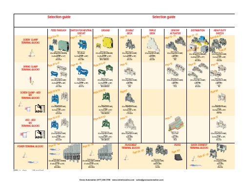
ABB EntrelecSommaireBU0402061SNC 160 003 C0205SummarySelection guide ....................................................................................page 1Screw clamp ........................................................................................page 2Feed through and ground terminal blocks .......................................................page 2 - 5 to 10Single pole, multiclamp terminal blocks..........................................................................page 4Feed through terminal blocks - Double-deck................................................................page 11Feed through terminal blocks - Triple-deck...................................................................page 12Three level sensor, terminal blocks without ground connection...................................page 13Three level sensor, terminal blocks with ground connection ........................................page 14Terminal blocks for distribution boxes, double deck + protection .......................page 15 - 16Interruptible terminal blocks for neutral circuit......................................................page 17 - 18Distribution : phase, ground terminal blocks .......................................................page 19 to 21Single pole or four pole distribution blocks..........................................................page 22 to 24Heavy duty switch terminal blocks with blade......................................................page 25 - 26Heavy duty switch terminal blocks with push-turn knob..............................................page 26Heavy duty switch terminal blocks with contact control pull lever...............................page 29Heavy duty switch terminal blocks with blade - Double-deck .....................................page 27Fuse holder terminal blocks for 5x20 mm (.197x.787 in.) and 5x25 mm (.197x.984 in.)or 6.35x25.4 mm (1/4x1 in.) and 6.35x32 mm (1/4x11/4 in.) fuse s.........................................page 28 - 29Fuse holder terminal blocks for 5x20 mm (.197x.787 in.) and 5x25 mm (.197x.984 in.) fuses -Double-dec k.....................................................................................................................page 27Terminal blocks for test circuits with sliding bridge ......................................................page 30Terminal blocks for metering circuits.............................................................................page 31ESSAILEC terminal blocks.............................................................................................page 32Safety connection terminal blocks ................................................................................page 33Miniblocks for EN 50045 (DIN 46277/2) rail ..........................................................page 34 - 35Spring clamp ......................................................................................page 36Angled terminal blocks - Feed through and ground .....................................................page 36Feed through and ground terminal blocks ...........................................................page 37 to 41Feed through terminal blocks - Double deck ................................................................page 42Terminal blocks for sensors / actuators ........................................................................page 42Terminal blocks for distribution boxes...........................................................................page 43Switch terminal blocks for neutral conductor........................................................page 44 - 45Heavy duty switch terminal blocks with blade..............................................................page 46Fuse holder terminal blocks for 5x20 mm (.197x.787 in.) and 5x25 mm (.197x.984 in.) fuse s....page 47Miniblocks Spring clamp ......................................................................................page 48 to 52ADO - Screw clamp ...........................................................................page 53Feed through and ground terminal blocks ...........................................................page 53 to 56Feed through and ground terminal blocks - Double-deck............................................page 57Heavy duty switch terminal blocks with blade..............................................................page 58Fuse holder terminal blocks for 5x20 mm (.197x.787 in.) and 5x25 mm (.197x.984 in.) fuse s ......page 59 - 60Miniblocks ADO - Screw clamp............................................................................page 61 to 65ADO - ADO .........................................................................................page 66Feed through and ground terminal blocks ...........................................................page 66 to 69Feed through and ground terminal blocks - Double-deck............................................page 70Terminal blocks for sensors / actuators ........................................................................page 71Heavy duty switch terminal blocks with blade..............................................................page 72Fuse holder terminal blocks for 5x20 mm (.197x.787 in.) and 5x25 mm (.197x.984 in.) fuse s ......page 73 - 74Miniblocks ADO - ADO .........................................................................................page 75 to 79Accessories ADO ...........................................................................................................page 80Power terminal blocks .............................................................page 81 to 84Quick-connect terminal blocks .................................................page 85 - 86Terminal blocks for railway applications ................................page 87 to 97Pluggable terminal blocks .....................................................page 98 to 100Accessories......................................................................................page 101Marking..................................................................................page 102 to 104GrossAutomation(877)268-3700··*************************PR30PR3.Z2PR3.G2PR5PR4PR1.Z2Rated wire size :Rated wire size :Rated wire size :Rated wire size :Mounting railsShield terminals forcollector barMarking tableHorizontal Rated wire size :0.5 to 16 mm² (22 to 8 AWG)Rated wire size :Rated wire size :Rated wire size :P a g e t o 29e30 t o 32ag e e3P a ge 8 t o 60a g e6t o 6574P a ge 7 t o 79P a ge 9P a g P a gGrossAutomation(877)268-3700··*************************2ABB Entrelecd010830402051SNC 160 003 C0205MA 2,5/5 - 2.5 mm² blocks - 5 mm .200" spacingAccessoriesGrossAutomation(877)268-3700··*************************3ABB Entrelec D010740402051SNC 160 003 C0205M 4/6 - 4 mm² blocks - 6 mm .238" spacingAccessoriesGrossAutomation(877)268-3700··*************************4ABB EntrelecD011030402051SNC 160 003 C0205M 4/6.3A - 4 mm² blocks - 6 mm .238" spacingM 4/6.4A - 4 mm² blocks - 6 mm .238" spacingGrossAutomation(877)268-3700··*************************5ABB Entrelec D010840402051SNC 160 003 C0205M 6/8 - 6 mm² blocks - 8 mm .315" spacingAccessoriesGrossAutomation(877)268-3700··*************************6ABB EntrelecD010850402051SNC 160 003 C0205M 10/10 - 10 mm² blocks - 10 mm .394" spacingAccessoriesGrossAutomation(877)268-3700··*************************7ABB Entrelec D010860402051SNC 160 003 C0205M 16/12 - 16 mm² blocks - 12 mm .473" spacingAccessoriesGrossAutomation(877)268-3700··*************************8ABB EntrelecD010870402051SNC 160 003 C0205M 35/16 - 35 mm² blocks - 16 mm .630" spacingGrossAutomation(877)268-3700··*************************M 95/26 - 95 mm² blocks - 26 mm 1.02" spacingM 70/22.P - 70 mm² ground block with rail contact - 22 mm .630" spacingSelection35 mm / 1.37"12 mm / 0.47"14-30 Nm / 124-260 Ib.in 1.2-1.4 Nm / 10.6-12.3 Ib.in1000600600415400400577070240 mm 2500 MCM 500 MCM 10 mm 2 6 AWG 6 AWG IEC UL CSANFC DIN0.5 - 160.5 - 100 AWG-600 MCM 2 AWG-500 MCM 50 - 30035 - 24018-6 AWGD 150/31.D10 - 150 mm² blocks - 31 mm 1.22" spacingCharacteristicsD 240/36.D10 - 240 mm² blocks - 36 mm 1.41" spacingSelectionWire size main circuit mm² / AWG VoltageV Current main circuit A Current outputARated wire size main circuit mm² / AWG Rated wire size outputmm² / AWG Wire stripping length main circuit mm / inches Wire stripping length output mm / inches Recommended torque main circuit Nm / Ib.in Recommended torque outputNm / Ib.inSolid Stranded Solid Stranded Wire size output mm² / AWG9.5 mm / .37"0.5-0.8 Nm / 4.4-7.1 Ib.in5003003003220204 mm 212 AWG12 AWG0.2 - 422-12 AWG 22-12 AWG 0.22 - 4IEC ULCSANFC DINCharacteristicsWire size mm² / AWGSolid Stranded D 4/6.T3 - 4 mm² blocks - 6 mm .238" spacingSelectionVoltage V CurrentARated wire sizemm² / AWG Wire stripping length mm / inches Recommended torqueNm / Ib.inM 4/6.T3.P - 4 mm² block - 6 mm .238" spacingD 2,5/6.D - 2.5 mm² blocks - 6 mm .238" spacingD 2,5/6.DL - 2.5 mm² blocks - 6 mm .238" spacingD 2,5/6.DPA1 - 2.5 mm² blocks - 6 mm .238" spacingD 2,5/6.DPAL1 - 2.5 mm² blocks - 6 mm .238" spacingD 4/6... - 4 mm² blocks - 6 mm .238" spacingD 4/6.LNTP - 4 mm² closed blocks - 17.8 mm .700" spacingMA 2,5/5.NT- 2.5 mm² block - 5 mm .200" spacingAccessories**SFB2 : 16 to 35 mm² 6 to 2 AWG H= 3 mm/.12"M 10/10.NT- 10 mm² block - 10 mm .394" spacingAccessories(1) Except for M 35/16 NT (closed block)*SFB1 : 0.5 to 35 mm² 18 to 2 AWG H= 7 mm/.28"**SFB2 : 16 to 35 mm² 6 to 2 AWG H= 3 mm/.12"MB 4/6... - 4 mm² blocks - 6 mm .238" spacingMB 6/8... - 6 mm² blocks - 8 mm .315" spacingMB 10/10... - 10 mm² blocks - 10 mm .394" spacingBRU 125 A - 35 mm² block - 27 mm 1.063" spacingBRU 160 A - 70 mm² block - 35.2 mm 1.388" spacingBRU 250 A - 120 mm² blocks - 44.5 mm 1.752" spacingBRU 400 A - 185 mm² block - 44.5 mm 1.752" spacingAccessoriesAccessoriesBRT 80 A - 16 mm² block - 48 mm 1.89" spacingBRT 125 A - 35 mm² block - 48 mm 1.89" spacingBRT 160 A - 50 mm² block - 50 mm 1.97" spacing9.5 mm / .37"0.5-0.6 Nm / 4.4-5.3 Ib.in4003003002010104 mm 210 AWG 12 AWG 0.5 - 422-10 AWG20-12 AWG0.5 - 2.5IEC ULCSANFC DINMA 2,5/5.SNB - 2.5 mm² blocks - 5 mm .200" spacingCharacteristicsM 4/6.SNB - 4 mm² blocks - 6 mm .238" spacingSelectionWire size mm² / AWGVoltage V CurrentARated wire sizemm² / AWG Wire stripping length mm / inches Recommended torqueNm / Ib.inSolid StrandedM 6/8.SNB - 6 mm² blocks - 8 mm .315" spacing - blade switchingSelectionAccessoriesM 4/8.D2.SF - for fuses 5x20 mm .197x.787 in. and 5x25 mm .197x.984 in. -4 mm² blocks - 8 mm .315" spacingM 4/6.D2.SNBT - 4 mm² blocks - 6 mm .238" spacing - blade switchM 4/8.SF- 4 mm² blocks - 8 mm .315" spacingM 4/8.SFL - 4 mm² blocks - 8 mm .315" spacing12 mm / .472"1.2-1.4 Nm / 10.6-12.3 Ib.in800(1)60060016252510 mm 210 AWG8 AWG0.5 - 1622-10 AWG 22-8 AWG 0.5 - 10IEC ULCSANFC DINCBD2SML 10/13.SF - for fuses 6.35x25.4 mm 1/4x1 in. and 6.35x32 mm 1/4x11/4 in. -10 mm² blocks - 13 mm .512" spacingSelectionAccessoriesCharacteristicsWire size mm² / AWGVoltage V CurrentARated wire sizemm² / AWG Wire stripping length mm / inches Recommended torqueNm / Ib.inSolid Stranded (1) Insulation voltage of terminal block - operating voltage : according to fuse.M 4/6.D2.2S2... - 4 mm² blocks - 6 mm .238" spacing11 mm / .43"0.8-1 Nm / 7.1-8.9 Ib.in50060030306 mm 28 AWG0.5 - 1022-8 AWG0.5 - 6IECULCSANFC DINM 6/8.ST... - 6 mm² blocks - 8 mm .315" spacingCharacteristicsWire size mm² / AWGVoltage V CurrentARated wire sizemm² / AWG Wire stripping length mm / inches Recommended torqueNm / Ib.inSolid Stranded M 6/8.STA - 6 mm² blocks - 8 mm .315" spacing(3)Only for M 6/8.STAM 4/6.ST- 4 mm² blocks - 6 mm .236" spacingBNT...PC...(2) Only for M10/10.ST-SnThe PREM IUM solution for testing the secondary circuits of current or voltage transformers.ESSAILEC, approved by the major electricity utilities, remains the premium choice for the energy market.Implemented in the transformers secondary circuits, ESSAILEC thanks to its intelligent “make before break” design eases and secures any intervention. Cutting the energy supply is avoided with zero risk for the operator.The plug and socket connection cuts cost installation as well as in-situ wiring errors. ESSAILEC is ideal for the wiring of sub-assemblies in the secondary circuits.ESSAILEC terminal blocksProtection relays,Protection relays,Testing :The ESSAILEC socket supplies energy to the protection or counting devices. The insertion of the test plug, which is connected to the measurement equipment, allows the testing of the devices, without perturbing the circuit.ESSAILEC blocks are well adapted to current or voltage measurement :-Current sockets with make before break contacts and pre-wired test plug for current measures-Voltage sockets with open contacts and pre-wired test plug for voltage measures-Up to 4 ammeters or 4 voltmeters connected to the test plugDistributing :The ESSAILEC plug is continuously mounted on the socket to supply current or voltage to secondary circuits sub assemblies.ESSAILEC blocks extreme versatility allow :-Safe current distribution with current socket with mobile contacts since the secondary circuit is not cut when plug is removed-Voltage or polarity distribution with dedicated voltage or polarity socket with closed contactESSAILEC is designed to offer :Great flexibility :-Connection multi contacts « plug and play »-Panel, rail, rack fixed mounting or stand-alone connector -Two wiring technologies, up to 10 mm²Extreme reliability :-Non symmetric blocks -Coding accessories -IP20 design -Locking system -Sealed coverR S T NFor technical characteristics and complete part numbers list, please ask for the ESSAILEC catalog10005006003225254 mm 21.65 mm²12 AWG 13 mm / .51"IECB.SCSANFC DINTS 50-180.5 - 0.8 Nm /4.4 - 7.1 Ib.in0.2 - 422-12 AWG0.22 - 40.5 - 1.50.28 - 1.6580050060041252562.512 AWG 13 mm / .51"0.8 - 1 Nm / 7.1 - 8.9 Ib.inIECB.S CSANFC DINTS 50-180.5 - 1020-12 AWG0.5 - 60.28 - 2.590050060046406510 mm 26 mm² 6 AWG 14 mm / .55"IECB.S UL/CSANFC DINTS 50-181.2 - 1.4 Nm / 10.6 - 12.3 Ib.in0.5 - 1620 - 6 AWG0.5 - 100.28 - 6M 4/6.RS - 4 mm² blocks - 6 mm .238" spacingCharacteristicsWire size mm² / AWGVoltage V CurrentARated wire sizemm² / AWG Wire stripping lengthmm / inches Recommended torque (screw)Nm / Ib.inSolid wire Stranded wire Solid wire Stranded wire Screw clampLugsM 6/8.RS - 6 mm² blocks - 8 mm .315" spacingCharacteristicsWire size mm² / AWGVoltage V CurrentARated wire sizemm² / AWG Wire stripping lengthmm / inches Recommended torque (screw)Nm / Ib.inSolid wire Stranded wire Solid wire Stranded wire Screw clampLugspending M 10/10.RS - 10 mm² blocks - 10 mm .394" spacingCharacteristicsWire size mm² / AWGVoltage V CurrentARated wire sizemm² / AWG Wire stripping lengthmm / inches Recommended torque (screw)Nm / Ib.inSolid wire Stranded wire Solid wire Stranded wire Screw clampLugspending SelectionAccessories(1) Only for block M 4/6.RS (4) For blocks M 4/6.RS and M 6/8.RS(2) Only for block M 6/8.RS(3) Only for block M 10/10.RSDR 1,5/4 - 1.5 mm² blocks - 4 mm .157" spacingDR 1,5/5... - 1.5 mm² blocks - 5 mm .200" spacing。
《ALCOR量产工具操作手册》
ALCOR量产工具操作手册2012.11.22目录1.运行环境 (1)2.主要功能 (1)2.1FLASH支持部分 (1)2.2U盘制作功能 (1)3.快速使用方法 (2)4.设定界面详细说明 (3)4.1主界面 (3)4.2密码设定 (4)4.3存储器设定 (5)4.3.1存储器类别 (5)4.3.2鼠产设定 (5)4.4装置方式设定 (8)4.4.1普通盘 (8)4.4.2本地盘 (9)4.4.3只读盘 (9)4.4.4加密盘 (10)4.4.5AES 盘 (10)4.4.6AutoRun 盘 (10)4.5 U盘信息设定 (12)4.6坏磁区设定 (13)4.7其它设定 (15)4.8界而显示 (16)4.9导出配置和导入配置 (17)5.MP错误代码对照表 (18)6.常见错误详解 (21)1.运行环境适用J - Wmdows XP, Wui7,Win8。
该软件是绿色版的,不用安装即可以使用。
2.主要功能2.1 FLASH支持部分1)最多可以16个U盘同时虽产。
2)支持不同型号的FLASH同时吊产,并可单独停止或开始任意一颗的吊:产。
3)自动识别FLASH型号、ID、CE数目,也可手动选择FLASH型号进行昂产。
4)支持单贴、双贴、单通道和双通道。
5)''低格检测、'设定,可■支持Half Page及其它特殊状况的FLASH,6)提供手动选择ECC设定。
7)有高级格式化和低级格式化两种扫描方式:a.高级格式化指扫描时直接读取FLASH的坏块信息,分为全新、全新+AA55、量产过和清空四个扫描级别:全新:直接读取原厂坏块信息。
全新+AA55:全新扫描+简单的检测。
量产过:直接读取上一次量产写入的坏块信息(必须是该量产I.具呐产过)。
清空:将FLASH存储的信息全部清空。
b.低级格式化指扫描时写数据到FLASH再读出来比较以确定坏块,扫描级别分两大类:全面扫描:对FLASH的所有位置进行检测。
ARM HSSTP II Active Probe 用户手册说明书

User ManualV2.6, August 2023/startGeneral safety instructionsPlease read the following safety precautions carefully before putting this device to use to avoid any personal injuries, damage to the instrument, or to the target system. Use this instrument only for its intended purpose as specified by this manual to prevent potential hazards.Use included power cord and power supplyThe enclosed power supply has been approved for use by iSYSTEM. Please contact iSYSTEM if you need to consider an alternative power.Use grounding wirePrior to applying power to either the BlueBox or the target, connect the device and the target system together with the included grounding wire. This is to avoid potential damage caused by any voltage difference between the device and the target system.Use proper overvoltage protectionEnsure proper protection to avoid exposing the BlueBox device or the operator to overvoltage surges (e.g. caused by thunderstorm, mains power).Do not operate without coverDo not operate the device with cover removed.Avoid circuit and wire exposureDo not touch exposed components or wires when the device is powered.Do not operate with suspected damageIf you suspect damage may have occurred, the BlueBox device must be inspected by qualified service personnel before further operation.Do not operate the device outside its rated supply voltage or environmental rangeConsult with iSYSTEM before using equipment outside of the parameters provided in this manual.This symbol is used within the manual to highlight further safety notices.ContentsPackage content (4)Specifications (5)Operation (6)mDIO Cable (8)40-pin Samtec ERF8 to 20-pin 2.54mm ARM Converter (9)40-pin Samtec ERF8 to 10-pin 1.27mm CoreSight and 40-pin Samtec ERF8 HSSTP Converter (10)10-pin 1.27mm CoreSight to 20-pin 2.54mm ARM Converter (13)40-pin Samtec / USB-C to USB-C (HSSTP) Switch (14)Hardware Setup and Configuration (18)Accessories (19)Active Probe ARM HSSTP II allows debugging, tracing and testing ARM® Cortex™ architectures. It supports both the JTAG debug interface and ARM High-Speed Trace Port (HSSTP). Its small and compact hardware size allows for connecting to a target microcontroller in a confined space as far as 10 m away. The Active Probe supports up to 4 parallel HSSTP lanes, running at a maximum bitrate of 5Gbps.The ARM HSSTP II Active Probe kit is delivered with the following components:ARM HSSTP II Active Probe 1m FNet CableSamtec40 -to 20-pin JTAGARM AdapterOrdering code: IC57125-1Ordering code:BB-FNET-100Ordering code:IASAM40ARMPIN20Blue colored signals are trace signals.Signal direction definition:O - Output from the Active Probe to the target microcontrollerI - Input to the Active Probe from the target microcontrollerThe target microcontroller connector is a Samtec ERF8 series, rugged high-speed socket, part number ASP-130367-01.B – mDIO port marked as TRIG on the housingmDIO port provides two digital signals, which can interact with the embedded target. Each can be configured either for input or output operation.mDIO port on the Active ProbeC – The indicator light provides the status of the Active Probe as follows:Permanently green – Powered on and ready to use.Blinking green – Establishing connection with the BlueBox.Blinking blue – Reprogramming SPLASH.Permanently magenta – Golden image loaded and ready to use.D – FNet connector, that connects the Active Probe to the iC5700 BlueBox. The FNet cable is delivered with the Active Probe.When powering on the system, switch the iC5700 on before powering on the target. When powering down the system, power off the target before powering off the iC5700!UseConsult with iSYSTEM before attempting to use any other accessory.Ordering code BB-AP-MDIO-20mDIO Cable is used to connect the Active Probe mDIO port with the signals around the debugged microcontroller, which can then be either read or controlled by the debugger. For example, the debugger can periodically service an external watchdog through the mDIO output or just read and record an external signal through the mDIO input. It must be ordered separately. Length of the cable is 20 cm.Ordering code IASAM40ARMPIN20In conjunction with this 40-pin Samtec ERF8 to 20-pin 2.54 ARM converter delivered in the package, the Active Probe can be connected to the target board featuring a 20-pin 2.54 mm ARM target debug connector providing the JTAG debug interface.This converter is required only when the Active Probe is to be connected to the embedded targetdebug interface without the ARM HSSTP tracethe Active Probe.Signal Direction is described from the BlueBox perspective.Ordering code IASAM40HSSTP-JTAGSAM Normally 40-pin ERF8 ARM HSSTP connector provides both, ARM HHSTP trace interface and JTAG or SWD debug interface. However, some targets for some reason don’t connect debug interface to this connector and provide the debug JTAG/SWD interface on a separate debug connector (10-pin 1.27mm CoreSight). Using this adapter, the Active Probe can be properly connected to such target.This converter is required only when the Active Probe is to be connected to the embedded targetJTAG/SWD interface physically connected but has10-pin 1.27 mm CoreSight target debug connector.The adapter doesn’t come along the Active Probe and has to be ordered separately.The converter has the following pinouts:A – 40-pin Samtec ERF8 connector providing merged JTAG/SWD debug signals (C on the image) and the HSSTP trace signals (B on the image) signals, to which the Active ProbeB – 40-pin Samtec ERF8 connector which connects to target development board with 40-pinBlue colored signals are trace signals.C – 10-pin CoreSight connector which connects to the target development board exposingSignal Direction is described from the BlueBox perspective.Related to the just described converter IASAM40HSSTP-JTAGSAM, the target development board can also feature a 20-pin 2.54 mm ARM target debug connector instead of the 10-pin 1.27 mm CoreSight. In order to connect the C part of the IASAM40HSSTP-JTAGSAM to this connector, another converter IA10PINCS20PINARM-1 is required, converting from ARM 20-pin 2.54mm to 10-pin 1.27 CoreSight. The IA10PINCS20PINARM-1 connects to the target and then the ‘C’ point of the IASAM40HSSTP-JTAGSAM connects on top of it.Ordering code IA10PINCS20PINARM-1This converter is required only when the Active Probe is to be connected to the embedded target providing the 20-pin 2.54 mm ARM target debug connector exposing only the debug interface without the ARM HSSTP trace interface. No trace interface (e.g. SWO, parallel) is supported with this converter. The converter is delivered along the Active Probe. Refer to ARM HSSTP II Active Probe User Manual for more information.* nTRST is permanently pulled upSignal Direction is described from the BlueBox perspective.Ordering code IEA-SWITCH-SAM40USBCThrough this hardware switch, you can conveniently connect·ARM HSSTP II Active Probe·and a host PC via a standard USB-C connectionto NVIDIA Orin device (connection marked as ORIN USB-C) at the same time. This switch is optional and must be ordered separately.A use case is that an application is programmed by the PC-based flash programming utility through the USB-C connection, and later, the application is debugged using the ARM HSSTP II Active Probe. Refer to the Technical Note NVIDIA Orin: USB port functionality switching for a use case where the switching can be automated.Switch configurationConnectorsThe switch features two USB-C connectors:·ORIN USB-C with a custom pinout for connection with the NVIDIA Orin device,·HOST USB-C for connection with the host PC (standard USB connection).Blue colored signals are trace signals.* Pulled down with 5k1 resistor.Blue colored signals are trace signals.Signal Direction is described from the BlueBox perspective.When connecting the BlueBox to a target for the first time, doubleadapterfailure.OrientationWhen connecting the switch ORIN USB-C connector to NVIDIA Orin target, make sure the connector is oriented correctly. Pay attention to the ORIENTATION LED indicator located on the Switch. The green LED lits when ORIN USB-C connector is properly connected to the NVIDIA target. If the red LED lits, rotate the ORIN USB-C connection.·Red – Wrong·Green – OKFor detailed visual presentation of the hardware setup and configuration, refer tostarted tutorial1. Connect the power supply cable. BlueBox should be switched off.2. First connect via USB. Later you can configure TCP/IP connection to work remotely.3. Connect the Grounding wire to the BlueBox and the Target.IfBlueBox and the Target can exceed well over 1000V even before any of the devices arepoweredleading to the possible destruction of electronic components.4. Connect FNet cable of Active Probe to the BlueBlux FNet port.Although it looks similar to the HDMI interface, theHDMI or any HDMI accessoriesConnecting iSYSTEM hardware to HDMI accessories will damage the hardware and willrender the iSYSTEM hardware warranty void.5. Power ON the hardware in the following order:a.BlueBoxb.Target6. Install winIDEA and create a new workspace.7. Configure Debug channel modes via Hardware / CPU Options / SoC.For troubleshooting refer to Knowledge Base - .More general settings are described in winIDEA Help.Please refer to the iC5700 BlueBox for all current iC5700 accessories.More information about our products onVisit our website for:·Support - /support ·Tutorials - /getting-started ·Knowledge Base - 。
- 1、下载文档前请自行甄别文档内容的完整性,平台不提供额外的编辑、内容补充、找答案等附加服务。
- 2、"仅部分预览"的文档,不可在线预览部分如存在完整性等问题,可反馈申请退款(可完整预览的文档不适用该条件!)。
- 3、如文档侵犯您的权益,请联系客服反馈,我们会尽快为您处理(人工客服工作时间:9:00-18:30)。
To :REVISION STATUSRevision Notice Description PageRev.Date0.0 First revision (Tentative) -- 2006.06.06CONTENTS1. OVERVIEW (4)2. ABSOLUTE MAXIMUM RATINGS (5)3. ELECTRICAL CHARACTERISTICS (5)3.1TFT LCD Power Voltage (5)3.2TFT LCD Power Current (6)4. INTERFACE CONNECTION (7)5. INPUT SIGNAL(DE ONLY MODE) (9)5.1 Horizontal Timing sequence (9)5.2 Vertical Timing sequence (9)5.3 Timing Specification (10)5.3.1 Horizontal Timing Specification (10)5.3.2 Vertical Timing Specification (10)5.4 Color Data Assignment (11)6. BLOCK DIAGRAM (12)7. MECHANICAL DIMENSION (13)7.1 Front side (13)7.2 Rear Side (14)8. OPTICAL CHARACTERISTICS (15)1. OVERVIEWCLAS070VA01 is 7" color TFT-LCD(Thin Film Transistor Liquid Crystal Display)modulecomposed of LCD panel,driver ICs,control circuit.The 7.0"screen produces a high resolution image that is composed of 800×480 pixelelements in a stripe arrangement.Display 262K colors by 6 Bit R.G.B signal input.Inverterfor backlight and Drive board for panel are not included in this module.General specifications are summarized in the following table:ITEM SPECIFICATION Panel Size 7 inch(panel diagonal)Display Area (mm) 152.4(W)×91.44(H)Number of Pixels 800(H)×3×480(V)Pixel Pitch (mm) 0.1905(H)×0.1905(V)Color Pixel Arrangement RGB vertical stripeDisplay Mode Normally whiteNumber of colors 262,144Panel Transmittance(%) 6.0Mechanical Dimension(mm) 161.8(W) × 101.4(H) × 1.7(D) ; Drive board for panel is not includeddegree(H),100degree(V)Viewing Angle(BL on,CR≧10) 140Power consumption 0.6W(Typ)Electrical Interface(data) TTLViewing Direction 6 o´clockSurface Treament Anti-Glare,Hardness:3H2. ABSOLUTE MAXIMUM RATINGSITEM SYMBOL MIN MAX UNIT NOTEDigital power voltage(Source)VCC(S) -0.5 5 V Digital power voltage (Gate) VCC(G) -0.3 6 V Analog power voltage AVDD -0.5 12.0 V Gamma voltage VR1~VR50.4AVDD AVDD+0.3 Gamma voltage VR6~VR10-0.3 0.6AVDD V Gate On voltage VDDG -0.3 40 V [Note 1] Gate Off voltage VEEG -20 0.3 V [Note 1]T 4 10m s T 3 10m s ≦≦T 5 10m s ≦T 6 10m s ≦T 8<T 7 10m s≦[Note 2] Common Power Voltage propose to electrical charateristics of power voltage.3.2TFT LCD Power CurrentITEM SYMBOL CONDITIONMIN TYPE MAX UNITNOTEDigital power current(Source)IVCC(S) VCC(S) 3.3V - 3.0 6.0 mA Digital power current (Gate) IVCC(G) VCC(G) 3.3V 100 250uA Analog power current IAVDD AVDD 9.6V - 40 100mA Gate on power current IVDDG VDDG 15V - - 400 uA Gate off power current IVEEG VEEG -6V - - -400uA Note1 Note1:SPEC(TYPE):64 gray test pattern SPEC(MAX):Black test pattern4. INTERFACE CONNECTIONPin NO. SYMBOL DESCRIPTION1 VCOM Common Voltage2 VCOM Common Voltage3 DIO1 Horizontal start Pulse Signal I/O4 VCC(S) Power Supply for Digital Circuit of Source IC5 CLK Horizontal Clock6 SHL Select Left / Right Shift7 D00 Red Data ( LSB )8 D01 Red Data9 D02 Red Data 10 D03 Red Data 11 D04 Red Data 12 D05 Red Data ( MSB ) 13 D10 Green Data ( LSB ) 14 D11 Green Data 15 D12 Green Data 16 D13 Green Data 17 D14 Green Data 18 D15 Green Data ( MSB ) 19 AVDD(S) Power Supply for Analog Circuit 20 VR1 Gamma Voltage Level 1 21 VR 2 Gamma Voltage Level 2 22 VR 3 Gamma Voltage Level 3 23 VR 4 Gamma Voltage Level 4 24 VR 5 Gamma Voltage Level 5 25 VR 6 Gamma Voltage Level 6 26 VR 7 Gamma Voltage Level 7 27 VR 8 Gamma Voltage Level 8 28 VR 9 Gamma Voltage Level 9 29 VR 10 Gamma Voltage Level 10 30 AVSS(S) Power Ground 31 D20 Blue Data ( LSB ) 32 D21 Blue Data 33 D22 Blue Data 34 D23 Blue Data 35 D24 Blue Data 36 D25 Blue Data ( MSB ) 37 LD Latch The Polarity of Output and Switch The New Data to Output 38 REV Control Signals are Inverted or not 39 POL Polarity Selection 40 GND(S) Power Ground 41 DIO2 Horizontal start Pulse Signal I/O 42 OEV Output Enable 43 UD Up / Down Control Pin 44 VCLK Vertical Clock 45 STVU Vertical start Pulse Signal I/O 46 STVD Vertical start Pulse Signal I/O 47 VDDG Gate ON Voltage 48 VEEG Gate OFF Voltage 49 VCC(G) Power Supply for Digital Circuit of Gate IC 50 GND(G) Power GroundRemarks:1) GND Pin must ground contact ,can not be floating. 2) SHL :Select left or rightSHL DIO1 DIO2 SHIFT 1 Input Output Right 0 Output Input Left3) UD:Shift up or down controlUD STVD STVU SHIFTOutput UP1 Input0 Output Input Down4) Gamma Voltage with load (Reference Only)ITEM VR1 VR2 VR3 VR4 VR5 VR6 VR7 VR8 VR9 VR10 UNIT(V) 9.21 7.75 7.27 6.88 5.92 4.01 3.04 2.66 2.14 0.735. INPUT SIGNAL(DE ONLY MODE) 5.1 Horizontal Timing sequence5.2 Vertical Timing sequence5.3 Timing Specification5.3.1 Horizontal Timing SpecificationSPECIFICATIONUNIT ITEM SYMBOLMin Typ MaxCLK Frequency Fclk 25 27 32 MHz CLK Period Tcph 31 37 40 ns CLK Pulse Width Tcw 8 - ns Data Set-up Time Tsu 4 - - ns Data Hold Time Thd 2 - - ns Propagation Delay of DIO2/1 Tphl 6 10 15 ns Time That The Last Data to LD Tld 1 - - Tcph Pulse Width of LD Twld 2 - - Tcph Time That LD to DIO1/2 Tlds 5 - - Tcph POL Set-up Time Tpsu 6 - - ns POL Hold Time Tphd 6 - - ns5.3.2 Vertical Timing SpecificationSPECIFICATIONUNIT ITEM SYMBOLMin Typ MaxVCLK Frequency Fvclk 26.930 33.8 Khz VCLK Rise Time Trck - - 100 ns VCLK Falling Time Tfck - - 100 ns VCLK Pulse Width (High & Low ) PWCLK 500- - ns STVD/STVU Set-up Time Tsu 200- - ns STVD/STVU Hold Time Thd 300- - ns Output Enabled pulse width Twcl 1 - usCPT 5.4 Color Data AssignmentCOLOR INPUT DATA R5 MSB BLACK RED(63) GREEN(63 BASIC ) COLOR BLUE(63) CYAN MAGENTA YELLOW WHITE RED(0) RED(1) RED(2) RED RED(62) RED(63) GREEN(0) GREEN(1) GREEN(2) GREEN GREEN(62 ) GREEN(63 ) BLUE(0) BLUE(1) BLUE(2) BLUE BLUE(62) BLUE(63) 0 0 0 0 0 0 0 0 0 0 0 0 0 0 0 0 0 0 1 1 0 0 0 1 1 0 0 0 1 1 0 0 0 1 1 0 0 0 1 1 0 0 0 0 1 0 0 0 0 0 0 0 0 0 0 0 0 0 0 0 0 0 0 0 1 0 0 0 1 1 1 0 0 0 0 1 0 0 0 1 1 1 0 0 0 0 1 0 0 0 1 1 1 0 0 0 0 1 0 0 0 1 1 1 0 0 0 0 1 0 0 0 1 1 1 0 0 1 R DATA R4 R3 R2 R1 R0 LSB 0 1 0 0 0 1 1 1 0 1 0 G5 MSB 0 0 1 0 1 0 1 1 0 0 0 0 0 1 0 1 0 1 1 0 0 0 0 0 1 0 1 0 1 1 0 0 0CHUNGHWA PICTURE TUBES, LTD.,G DATA G4 G3 G2 G1 G0 LSB MSB 0 0 1 0 1 0 1 1 0 0 0 0 0 1 0 1 0 1 1 0 0 0 0 0 1 0 1 0 1 1 0 0 0 0 0 0 1 1 1 0 1 0 0 0B DATA B5 B4 B3 B2 B1 B0 LSB 0 0 0 0 0 0 0 0 0 0 0 0 1 1 1 1 1 1 1 1 1 1 1 1 0 0 0 0 1 1 1 1 0 0 0 0 0 0 0 0 0 0 0 0 0 0 0 1 1 1 0 1 0 0 00 0 0 0 00 0 0 0 10 0 0 1 00 0 0 0 00 0 0 0 0 0 0 0 0 0 0 0 0 0 0 0 0 0 0 00 0 0 0 00 0 0 0 00 0 0 0 00 0 0 0 00 0 0 0 00 0 0 0 00 0 0 0 01 1 0 0 01 1 0 0 01 1 0 0 01 1 0 0 01 1 0 0 00 1 0 0 00 0 0 0 00 0 0 0 0 0 0 0 0 0 0 0 0 0 0 0 0 0 0 10 0 0 1 00 00 00 01 11 1 1 1 1 1 1 10 1[Note] (1) Definition of Gray Scale color(n):n is series of Gray Scale The more n value is, the bright Gray Scale. (2)Data:1-High,0-LowCPT Confidential11/16SPEC_CLAS070VA01_V0.0_大裕_100512CPTCHUNGHWA PICTURE TUBES, LTD.,6. BLOCK DIAGRAMTFT-LCD ModuleSource DriverCNGate DriverLCD Panel 800 X 3 X 480CPT Confidential12/16SPEC_CLAS070VA01_V0.0_大裕_100512CPTCHUNGHWA PICTURE TUBES, LTD.,7. MECHANICAL DIMENSION7.1 Front side 【Unit:mm】NOTE :Undefined tolerances to be +/-0.3CPT Confidential13/16SPEC_CLAS070VA01_V0.0_大裕_100512CPT 7.2 Rear SideCHUNGHWA PICTURE TUBES, LTD.,CPT Confidential14/16SPEC_CLAS070VA01_V0.0_大裕_100512CPTCHUNGHWA PICTURE TUBES, LTD., Ta=25℃ITEM SYMBOL -CR tr+tf φ θ CONDITION −− θ = φ = 0° Point-5 θ = φ = 0° CR≥10 Point-5 MIN. -300 -120 80 TYP. 6.0 400 30 140 100 MAX. --35 --UNIT % -ms ° ° Remarks -*1) *2) *3) *3)8. OPTICAL CHARACTERISTICSPanel Transmittance Contrast Ratio Response Time Viewing angle [Note] Horizontal VerticalMeasured moudle : Back Light Luminance = 3900 nit. *1) Definition of contrast ratio: These items are measured by BM-5A (TOPCON) in the dark room. (no ambient light). Measure contrast ratio on the below 5 points (refer to figure1, #1~# 5 point) and take the average value. Contrast ratio is calculated with the following formula : Contrast Ratio (CR)= (White) Luminance of ON ÷ (Black) Luminance of OFFFig8-1 Measuring point *2) Definition of Response Time.(White-Black)White(63th) 90% 90%Luminance10% tr10%Black(0) tfFig8-2 Definition of Response Time(White-Black) *3) Definition of Viewing Angle(θ,ψ),refer to Fig8-2 as below: These items are measured by EZ-CONTRAST(ELDIM) in the dark room. (no ambient light).CPT Confidential15/16SPEC_CLAS070VA01_V0.0_大裕_100512CPTCHUNGHWA PICTURE TUBES, LTD.,Fig8-3 Definition of Viewing AngleCPT Confidential16/16SPEC_CLAS070VA01_V0.0_大裕_100512。