思科、华为dhcp及中继代理配置实例
华为网络实验-利用DHCP服务(中继口)自动获取IP

华为⽹络实验-利⽤DHCP服务(中继⼝)⾃动获取IP⽬录实验原理第⼀步:客户端通过⼴播发送DHCP Discover 报⽂寻找服务器端第⼆步:服务器端通过单播发送DHCP Offer 报⽂向客户端提供IP地址等⽹络信息第三步:客户端通过⼴播DHCP Request 报⽂告知服务器端本地选择使⽤哪个IP地址第四步:服务器通过单播DHCP Ack报⽂告知客户端IP地址是合法可⽤的即客户端两次⼴播,服务器端两次单播实验⽬的通过DHCP服务(中继⼝)来⾃动获取IP具体操作1.SW1的命令1)进⼊系统界⾯并重命名为SW12)把e0/0/1⼝变为access⼝,同理e/0/0/2,e/0/0/3,e/0/0/4.3)把g0/0/1⼝变为trunk⼝2.R1的命令1)进⼊系统界⾯并重命名为R12)添加g/0/0/0和g/0/0/2的IP和⼦⽹掩码3)开通DHCP全局服务,添加单臂路由并让g/0/0/1成为中继⼝转到14.0.0.24)设置默认路由3.R2的命令1)进⼊系统界⾯并重命名为R2并添加g/0/0/2的IP和⼦⽹掩码,这边就不截图了,直接开始下⾯命令2)开始DHCP全局服务,添加g/0/0/1IP和⼦⽹掩码并让这个⼝也成为中继⼝转到14.0.0.23)添加3条静态路由4.R3的命令1)命名R2并添加⼝的IP和⼦⽹掩码2)开始DHCP服务,在接⼝处声明服务池3)第⼀个服务池R2那边的中继⼝(⽹络号、⼦⽹掩码、ip、dns)注:excluded-ip-address+IP ------排除IPstatic-bind ip-address+ip mac-address+mac地址 -----绑定ip和主机mac4)第⼆个服务池R1单臂路由的⼦接⼝5)第三个服务池R1单臂路由的另⼀个⼦接⼝6)设置⼀条静态路由即可(处于末梢端,并且是R2的直连路由)实验结果1)配置界⾯改为⾃动获取DHCP并抓包2)输⼊ipconfig /renew-----获取ip注:ipconfig /release----释放ip ⼀般不⽤同理,其他4台pc也能获取⾃⼰的ip,因为PC5我给它配了⼀个固定ip15.0.0.88并且与之mac绑定了3)全⽹互通(ping)实验总结DHCP服务的报⽂可以总结为两次客户端⼴播+两次服务器单播。
华为路由交换配置DHCP及DHCP中继

DHCP Server
DHCPACK(UNICAST)
DHCPREQUEST(BROADCAST) T2:使用时 间达到租 期的87.5% DHCPACK(UNICAST)
T
DHCP Relay 的通信过程
子网1
子网2
DHCP Server
DHCPDISCOVER DHCPOFFER DHCPREQUEST DHCPACK/NAK
配置从当前接口地址池分配地址,在接口视图下配置 dhcp select interface
DHCP Server配置(续)
创建DHCP全局地址池
请在系统视图下进行下列配置 ip-pool pool-name
配置动态分配的IP地址范围
请在DHCP地址池视图下进行下列配置 network ip-address mask [netmask ]
DHCP Relay 的通信过程分析(续)
DHCP Relay续订租约
子网1 DHCP Client
DHCPREQUEST(UNICAST)
子网2 DHCP Server
T1:使用时 间达到租 期的50%
DHCPACK(UNICAST)
T2:使用时 间达到租 期的87.5%
DHCPREQUEST(BROADC AST) DHCPACK(UNICAST)
xid
secs flags
由DHCP Client填充,从DHCP Client开始获得地址或地址续借 后所使用了的秒数。
八位中最左边的一位置位代表广播,反之代表单播。
DHCP报文中各个部分的含义
字段 ciaddr yiaddr siaddr giaddr chaddr sname file 含义 Client IP address,只有DHCP Client已经获得IP地址,并且能响应 ARP requests时,才能被填充。 ‘your’(Client)IP address bootstrap中,下一个Server的IP地址。 DHCP Relay代理的IP地址。 Client hardware address “服务器主机名”字段是一个空值终止串,由服务器填写。 Boot file name,是一个空值终止串。DHCPDISCOVER中是 “generic”名字或空字符;DHCPOFFER提供有效的目录路径全名。 可选参数域,定义的选项列表。DHCP报文“options”域的头四个八 位字节的十进制值分别为99、130、83、99,“options”域的剩余项 包括一列tagged参数。RFC 2132中介绍了全部的option的定义。
实验三:配置DHCP_中继代理
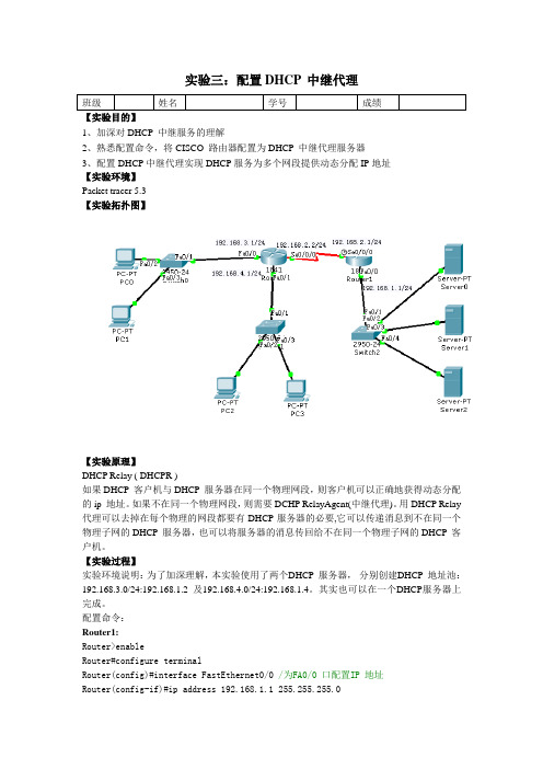
实验三:配置DHCP 中继代理班级姓名学号成绩【实验目的】1、加深对DHCP 中继服务的理解2、熟悉配置命令,将CISCO 路由器配置为DHCP 中继代理服务器3、配置DHCP中继代理实现DHCP服务为多个网段提供动态分配IP地址【实验环境】Packet tracer 5.3【实验拓扑图】【实验原理】DHCP Relay ( DHCPR )如果DHCP 客户机与DHCP 服务器在同一个物理网段,则客户机可以正确地获得动态分配的ip 地址。
如果不在同一个物理网段,则需要DCHP RelayAgent(中继代理)。
用DHCP Relay 代理可以去掉在每个物理的网段都要有DHCP服务器的必要,它可以传递消息到不在同一个物理子网的DHCP 服务器,也可以将服务器的消息传回给不在同一个物理子网的DHCP 客户机。
【实验过程】实验环境说明:为了加深理解,本实验使用了两个DHCP 服务器,分别创建DHCP 地址池:192.168.3.0/24:192.168.1.2 及192.168.4.0/24:192.168.1.4。
其实也可以在一个DHCP服务器上完成。
配置命令:Router1:Router>enableRouter#configure terminalRouter(config)#interface FastEthernet0/0 /为FA0/0 口配置IP 地址Router(config-if)#ip address 192.168.1.1 255.255.255.0Router(config-if)#no shutdownRouter(config-if)#exitRouter(config)#interface S0/0/0 /为S0/0/0 口配置IP 地址Router(config-if)#ip address 192.168.2.1 255.255.255.0Router(config-if)#clock rate 64000 /为S0/0/0 口配置串行链路时钟Router(config-if)#no shutdownRouter(config-if)#exitRouter(config)#router eigrp 10 /启用EIGRP 协议Router(config-router)#network 192.168.1.0 /将192.168.1.0 加入作用域Router(config-router)#network 192.168.2.0Router(config-router)#auto-summary /启用自动汇总Router0:Router>enableRouter#configure terminalRouter(config)#interface FastEthernet0/0Router(config-if)#ip address 192.168.3.1 255.255.255.0Router(config-if)#no shutdownRouter(config-if)#exitRouter(config)#interface FastEthernet0/1Router(config-if)#no shutdownRouter(config-if)#ip address 192.168.4.1 255.255.255.0Router(config-if)#no shutdownRouter(config-if)#exitRouter(config)#interface S0/0/0Router(config-if)#ip address 192.168.2.2 255.255.255.0Router(config)#router eigrp 10Router(config-router)#network 192.168.3.0Router(config-router)#network 192.168.2.0Router(config-router)#network 192.168.4.0Router(config-router)#auto-summaryRouter(config-router)#exitRouter(config)#int fa 0/0Router(config-if)#ip helper-address 192.168.1.4 /配置DHCP 中继代理。
HuaweiDHCP中继配置实例
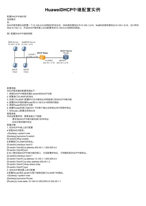
HuaweiDHCP中继配置实例配置DHCP中继⽰例组⽹需求如DHCP服务器应当配置⼀个10.100.0.0/16⽹段的IP地址池,DNS服务器地址为10.100.1.2/16,NetBIOS服务器地址10.100.1.3/16,出⼝⽹关地址10.100.1.4,并且DHCP服务器上应当配置有到10.100.0.0/16⽹段的路由。
图1 配置DHCP中继组⽹图配置思路DHCP服务器的配置思路如下:1. 使能DHCP中继服务器S-switch的DHCP功能2. 配置接⼝VLANIF2的地址3. 在接⼝VLANIF1配置IP以及中继地址并使能接⼝的DHCP中继功能4. 配置DHCP服务器Router到10.100.0.0/16⽹段的路由5. 使能Router的DHCP功能6. 配置Router的接⼝GE0/0/1下的客户端从全局地址池中获取IP地址7. 在Router上配置全局地址池数据准备完成此配置举例,需要准备以下数据:· 要实现DHCP中继功能的接⼝的IP地址· DHCP服务器的地址配置步骤1. 在DHCP中继上进⾏配置# 使能DHCP服务。
<Quidway> system-view[Quidway] sysname S-switch[S-switch] dhcp enable# 配置接⼝VLANIF2的地址。
[S-switch] interface vlanif 2[S-switch-Vlanif2] ip address 202.40.1.1 255.255.0.0[S-switch-Vlanif2] quit# 进⼊要实现DHCP中继功能的接⼝,为其配置IP地址、⼦⽹掩码和DHCP中继地址。
[S-switch] interface vlanif 1[S-switch-Vlanif1] ip address 10.100.1.1 255.255.0.0[S-switch-Vlanif1] ip relay address 202.40.1.2[S-switch-Vlanif1] dhcp select relay[S-switch-Vlanif1] quit2. 在DHCP服务器上进⾏配置# 配置Router到S-switch与客户端相连接⼝VLANIF1的路由。
华为路由器dhcp简单配置实例

华为路由器dhcp简单配置实例session 1 DHCP的工作原理DHCP(Dynamic Host Configuration Protocol,动态主机配置协议)是一个局域网的网络协议,使用UDP协议工作,主要有两个用途:给内部网络或网络服务供应商自动分配IP地址,给用户或者内部网络管理员作为对所有计算机作中央管理的手段,在RFC 2131中有详细的描述。
DHCP有3个端口,其中UDP67和UDP68为正常的DHCP 服务端口,分别作为DHCP Server和DHCP Client的服务端口;546号端口用于DHCPv6 Client,而不用于DHCPv4,是为DHCP failover服务,这是需要特别开启的服务,DHCP failover是用来做“双机热备”的。
DHCP协议采用UDP作为传输协议,主机发送请求消息到DHCP服务器的67号端口,DHCP服务器回应应答消息给主机的68号端口,DHCP的IP地址自动获取工作原理及详细步骤如下:1、DHCP Client以广播的方式发出DHCP Discover报文。
2、所有的DHCP Server都能够接收到DHCP Client发送的DHCP Discover报文,所有的DHCP Server都会给出响应,向DHCP Client发送一个DHCP Offer报文。
DHCP Offer报文中“Your(Client) IP Address”字段就是DHCP Server 能够提供给DHCP Client使用的IP地址,且DHCP Server会将自己的IP地址放在“option”字段中以便DHCP Client 区分不同的DHCP Server。
DHCP Server在发出此报文后会存在一个已分配IP地址的纪录。
3、DHCP Client只能处理其中的一个DHCP Offer报文,一般的原则是DHCP Client处理最先收到的DHCP Offer报文。
华为路由器DHCP配置实例
华为路由器DHCP配置实例常见的DHCP组网方式可分为两类:一种是DHCP服务器和客户端都在一个子网内,直接进行DHCP协议的交互;第二种是DHCP服务器和客户端分别处于不同的子网中,必须通过DHCP中继代理实现IP地址的分配。
无论那种情况下,DHCP的配置都是相同的。
1. 网络需求DHCP服务器为同一网段中的客户端动态分配IP地址,地址池网段10.1.1.0/24分为两个网段:10.1.1.0/25和10.1.1.128/25。
DHCP服务器两个Ethernet接口地址分别为10.1.1.1/25和10.1.1.129/25。
网段10.1.1.0/25内的地址租用期限为10天12小时,域名为,DNS地址为10.1.1.2,无NetBIOS地址,出口路由器地址为10.1.1.126;网段10.1.1.128/25网段内的地址租用期限为5天,DNS地址为10.1.1.2,NetBIOS地址为10.1.1.4,出口路由器的地址为10.1.1.254。
2. 配置步骤# 启动DHCP服务。
[Net1980] dhcp enable# 配置接口工作在DHCP服务器模式下,并从全局地址池中分配IP地址。
[Net1980] dhcp select global interface ethernet 0/0/0 to ethernet 0/0/1# 配置不参与自动分配的IP地址(DNS、NetBIOS和出口网关地址)。
[Net1980] dhcp server forbidden-ip 10.1.1.2[Net1980] dhcp server forbidden-ip 10.1.1.4[Net1980] dhcp server forbidden-ip 10.1.1.126[Net1980] dhcp server forbidden-ip 10.1.1.254# 配置DHCP地址池0的共有属性(地址池范围、DNS地址)。
华为DHCP全局、端口、中继配置
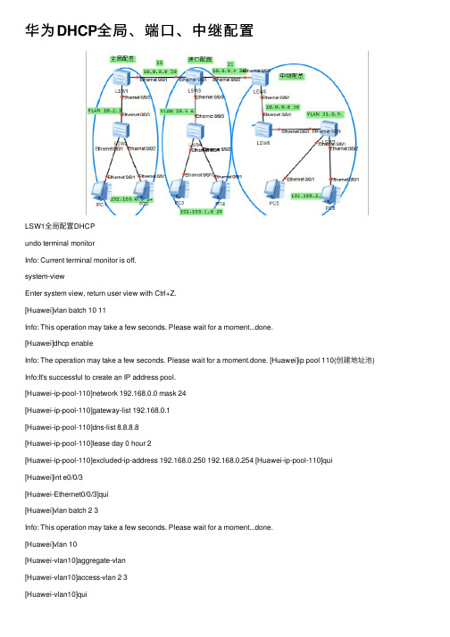
华为DHCP全局、端⼝、中继配置LSW1全局配置DHCPundo terminal monitorInfo: Current terminal monitor is off.system-viewEnter system view, return user view with Ctrl+Z.[Huawei]vlan batch 10 11Info: This operation may take a few seconds. Please wait for a moment...done.[Huawei]dhcp enableInfo: The operation may take a few seconds. Please wait for a moment.done. [Huawei]ip pool 110(创建地址池) Info:It's successful to create an IP address pool.[Huawei-ip-pool-110]network 192.168.0.0 mask 24[Huawei-ip-pool-110]gateway-list 192.168.0.1[Huawei-ip-pool-110]dns-list 8.8.8.8[Huawei-ip-pool-110]lease day 0 hour 2[Huawei-ip-pool-110]excluded-ip-address 192.168.0.250 192.168.0.254 [Huawei-ip-pool-110]qui [Huawei]int e0/0/3[Huawei-Ethernet0/0/3]qui[Huawei]vlan batch 2 3Info: This operation may take a few seconds. Please wait for a moment...done.[Huawei]vlan 10[Huawei-vlan10]aggregate-vlan[Huawei-vlan10]access-vlan 2 3[Huawei]int vlanif 10[Huawei-Vlanif10]ip address 192.168.0.1 24[Huawei-Vlanif10]dhcp select global[Huawei-Vlanif10]qui[Huawei]int vlanif 11[Huawei-Vlanif11]ip add 10.0.0.1 30[Huawei-Vlanif11]qui[Huawei]int e0/0/3[Huawei-Ethernet0/0/3]port link-type trunk[Huawei-Ethernet0/0/3]port trunk allow-pass vlan 2 3[Huawei-Ethernet0/0/3]int e0/0/1[Huawei-Ethernet0/0/1]port link-type access[Huawei-Ethernet0/0/1]port default vlan 11[Huawei-Ethernet0/0/1]qui[Huawei]ip route-static 192.168.1.0 24 10.0.0.2[Huawei]ip route-static 192.168.2.0 24 10.0.0.2[Huawei]ip route-static 10.0.0.4 30 10.0.0.2[Huawei]ip route-static 10.0.0.8 30 10.0.0.2[Huawei]LSW2undo terminal monitorInfo: Current terminal monitor is off.system-viewEnter system view, return user view with Ctrl+Z.[Huawei]vlan batch 2 3Info: This operation may take a few seconds. Please wait for a moment...done. [Huawei]int e0/0/1[Huawei-Ethernet0/0/1]port link-type access[Huawei-Ethernet0/0/1]port default vlan 2[Huawei-Ethernet0/0/1]int e0/0/2[Huawei-Ethernet0/0/2]port link-type access[Huawei-Ethernet0/0/2]port default vlan 3[Huawei-Ethernet0/0/2]int e0/0/3[Huawei-Ethernet0/0/3]port link-type trunk[Huawei-Ethernet0/0/3] User interface con0 is availableLSW3端⼝配置DHCPundo terminal monitorInfo: Current terminal monitor is off.sysEnter system view, return user view with Ctrl+Z.[Huawei]vlan batch 11 20 21 5 6Info: This operation may take a few seconds. Please wait for a moment...done.[Huawei]int vlanif 11[Huawei-Vlanif11]ip add 10.0.0.2 30[Huawei-Vlanif11]int vlanif 21[Huawei-Vlanif21]ip add 10.0.0.5 30[Huawei-Vlanif21]qui[Huawei]vlan 20[Huawei-vlan20]aggregate-vlan[Huawei-vlan20]access-vlan 5 6[Huawei-vlan20]qui[Huawei]dhcp enableInfo: The operation may take a few seconds. Please wait for a moment.done. [Huawei]int vlanif 20 [Huawei-Vlanif20]ip add 192.168.1.1 24[Huawei-Vlanif20]dhcp select interface[Huawei-Vlanif20]dhcp server dns-list 8.8.8.8[Huawei-Vlanif20]dhcp server lease day 0 hour 3[Huawei-Vlanif20]dhcp server excluded-ip-address 192.168.1.250192.168.1.254[Huawei-Vlanif20]qui[Huawei]int e0/0/1[Huawei-Ethernet0/0/1]port link-type access[Huawei-Ethernet0/0/1]port default vlan 11[Huawei-Ethernet0/0/1]int e0/0/2[Huawei-Ethernet0/0/2]port link-type access[Huawei-Ethernet0/0/2]port default vlan 21[Huawei-Ethernet0/0/2]int e0/0/3[Huawei-Ethernet0/0/3]qui[Huawei]ip route-static 192.168.1.0 24 10.0.0.1[Huawei]undo ip route-static 192.168.1.0 24 10.0.0.1[Huawei]ip route-static 192.168.0.0 24 10.0.0.1[Huawei]ip route-static 192.168.2.0 24 10.0.0.6[Huawei]ip route-static 10.0.0.8 24 10.0.0.6Info: The destination address and mask of the configured static route mismatched , and the static route 10.0.0.0/24 was generated.[Huawei]ip route-static 10.0.0.8 30 10.0.0.6[Huawei] User interface con0 is availableLSW4Huawei>undo terminal monitorInfo: Current terminal monitor is off.sysEnter system view, return user view with Ctrl+Z.[Huawei]vlan batch 5 6Info: This operation may take a few seconds. Please wait for a moment...done. [Huawei]int e0/0/1[Huawei-Ethernet0/0/1]port link-type access[Huawei-Ethernet0/0/1]port default vlan 5[Huawei-Ethernet0/0/1]int e0/0/2[Huawei-Ethernet0/0/2]port link-type access[Huawei-Ethernet0/0/2]port default vlan 6[Huawei-Ethernet0/0/2]int e0/0/3[Huawei-Ethernet0/0/3]port link-type trunk[Huawei-Ethernet0/0/3]port trunk allow-pass vlan 5 6[Huawei-Ethernet0/0/3] User interface con0 is availableLSW5中继配置DHCPundo ter mInfo: Current terminal monitor is off.sysEnter system view, return user view with Ctrl+Z.[Huawei]vlan batch 21 30[Huawei][Huawei]dhcp enableInfo: The operation may take a few seconds. Please wait for a moment.done. [Huawei]int vlanif 21[Huawei-Vlanif21]ip add 10.0.0.6 30[Huawei-Vlanif21]int vlanif 30[Huawei-Vlanif30]ip add 10.0.0.9 30[Huawei-Vlanif30]qui[Huawei]int vlanif 30[Huawei-Vlanif30][Huawei-Vlanif30] dhcp select global[Huawei-Vlanif30]qui[Huawei]ip pool 300Info:It's successful to create an IP address pool. [Huawei-ip-pool-300]network 192.168.2.0 mask 24 [Huawei-ip-pool-300]gateway-list 192.168.2.1[Huawei-ip-pool-300]dns-list 8.8.8.8[Huawei-ip-pool-300]lease day 0 hour 2[Huawei-ip-pool-300]qui[Huawei]int e0/0/1[Huawei-Ethernet0/0/1]port link-type access[Huawei-Ethernet0/0/1]port defaul vlan 30[Huawei-Ethernet0/0/1]int e0/0/2[Huawei-Ethernet0/0/2]port link-type access[Huawei-Ethernet0/0/2]port defaul vlan 21[Huawei-Ethernet0/0/2] User interface con0 is available [Huawei]ip route-static 192.168.0.0 24 10.0.0.5 [Huawei]ip route-static 192.168.1.0 24 10.0.0.5 [Huawei]ip route-static 10.0.0.0 30 10.0.0.5[Huawei]ip route-static 192.168.2.0 24 10.0.0.10LSW6undo terminal monitorInfo: Current terminal monitor is off.langu chineseChange language mode, confirm? [Y/N] y提⽰:改变语⾔模式成功。
思科模拟器——DHCP服务器中继实验
思科模拟器——DHCP服务器中继实验2017-7-9基于思科模拟器ZKY正品体育思科模拟器DHCP服务器中继实验【DHCP服务器中继案例1】只有⼀个⽹段的DHCP中继其中路由器作为DHCP服务器,交换机作为中继⼀、交换机配置过程Switch>Switch>enSwitch#confSwitch(config)#vlan 10 创建VLAN 10Switch(config-vlan)#exitSwitch(config)#int vlan 10Switch(config-if)#ip address 192.168.10.254 255.255.255.0 为VLAN 10配置地址Switch(config-if)#no shut 开启虚拟接⼝Switch(config-if)#exitSwitch(config)#int fa0/1Switch(config-if)#switchport access vlan 10 将fa0/1加⼊vlan 10Switch(config-if)#exitSwitch(config)#int fa0/24Switch(config-if)#no switchport 将交换⼝转换为路由⼝Switch(config-if)#ip adSwitch(config-if)#ip address 172.16.1.1 255.255.255.0Switch(config-if)#no shutSwitch(config-if)#exSwitch(config)#ip route 0.0.0.0 0.0.0.0 172.16.1.2Switch(config-if)#Switch(config-if)#exitSwitch(config)#int vlan 10Switch(config-if)#ip ?access-group Specify access control for packetsaddress Set the IP address of an interfacehello-interval Configures IP-EIGRP hello intervalhelper-address Specify a destination address for UDP broadcasts nat NAT interface commandsospf OSPF interface commandsproxy-arp Enable proxy ARPsplit-horizon Perform split horizonsummary-address Perform address summarizationSwitch(config-if)#ip helpSwitch(config-if)#ip helper-address 172.16.1.2Switch(config-if)#endSwitch#%SYS-5-CONFIG_I: Configured from console by consoleSwitch#sh ip routeCodes: C - connected, S - static, I - IGRP, R - RIP, M - mobile, B - BGPD - EIGRP, EX - EIGRP external, O - OSPF, IA - OSPF inter areaN1 - OSPF NSSA external type 1, N2 - OSPF NSSA external type 2E1 - OSPF external type 1, E2 - OSPF external type 2, E - EGPi - IS-IS, L1 - IS-IS level-1, L2 - IS-IS level-2, ia - IS-IS inter area* - candidate default, U - per-user static route, o - ODRP - periodic downloaded static routeGateway of last resort is 172.16.1.2 to network 0.0.0.0172.16.0.0/24 is subnetted, 1 subnetsC 172.16.1.0 is directly connected, FastEthernet0/24C 192.168.10.0/24 is directly connected, Vlan10S* 0.0.0.0/0 [1/0] via 172.16.1.2Switch#confConfiguring from terminal, memory, or network [terminal]?Enter configuration commands, one per line. End with CNTL/Z. Switch(config)#ip routingSwitch(config)#endSwitch#%SYS-5-CONFIG_I: Configured from console by consoleSwitch#wrBuilding configuration...⼆、路由器配置过程Router>enRouter#confRouter(config)#int f0/0Router(config-if)#ip address 172.16.1.2 255.255.255.0Router(config-if)#exitRouter(config)#ip dhcp ?excluded-address Prevent DHCP from assigning certain addressespool Configure DHCP address poolsRouter(config)#ip dhcp excluded-address 192.168.10.254 排除地址,避免客户端获得此IP地址产⽣冲突Router(config)#ip dhcp pool vlan10 (创建地址池vlan10)Router(dhcp-config)#? (通过?可以知道DHCP服务器可以配置哪些选项)default-router Default routersdns-server Set name serverexit Exit from DHCP pool configuration modenetwork Network number and maskno Negate a command or set its defaultsoption Raw DHCP optionsRouter(dhcp-config)#default-router 192.168.10.254 (为客户端配置默认⽹关)Router(dhcp-config)#dns-server 192.168.10.254 (为客户端配置DNS)Router(dhcp-config)#netRouter(dhcp-config)#network 192.168.10.0 255.255.255.0 (客户端所在⽹络及掩码)Router(dhcp-config)#end Router(config)#ip route 0.0.0.0 0.0.0.0 172.16.1.1Router(config)#int fa0/0Router(config-if)#no shut【DHCP服务器中继案例2】有多个⽹段的DHCP中继⼀、交换机配置过程Switch>enSwitch#conf tEnter configuration commands, one per line. End with CNTL/Z.1.创建vlan 10,vlan20,vlan 30Switch(config)#vlan 10Switch(config-vlan)#vlan 20Switch(config-vlan)#vlan 30Switch(config-vlan)#2.为3个vlan创建相应的IP地址,并在vlan中创建中继,指向DHCP服务器地址Switch(config)#interface vlan 10Switch(config-if)#ip address 192.168.10.254 255.255.255.0Switch(config-if)#ip helper-address 172.16.1.2Switch(config)#interface vlan 20Switch(config-if)#ip address 192.168.20.254 255.255.255.0Switch(config-if)#ip helper-address 172.16.1.2Switch(config-if)#exitSwitch(config)#interface vlan 30Switch(config-if)#ip address 10.0.0.1 255.0.0.0Switch(config-if)#ip helper-address 172.16.1.23.将fa0/1,fa0/11,fa0/21分别加⼊vlan 10,vlan 20,vlan 30 Switch(config)#interface fastEthernet 0/1Switch(config-if)#switchport access vlan 10Switch(config)#interface fastEthernet 0/11Switch(config-if)#switchport access vlan 20Switch(config-if)#exitSwitch(config)#interface fastEthernet 0/21Switch(config-if)#switchport access vlan 30Switch(config-if)#Switch(config-if)#4.将fa0/24设置为路由⼝,并设置IP地址Switch(config)#interface fastEthernet 0/24Switch(config-if)#no switchportSwitch(config-if)#ip address 172.16.1.1 255.255.255.252 Switch(config-if)#5.设置默认路由,指向下⼀跳地址(即路由器接⼝地址)Switch(config-if)#exitSwitch(config)#ip route 0.0.0.0 0.0.0.0 172.16.1.2Switch(config)#6.交换机开启路由功能(总是会忘记这个,忘记了N次了)Switch(config)#ip routing7.保存配置Switch(config)#exitSwitch#%SYS-5-CONFIG_I: Configured from console by console Switch#wrBuilding configuration...[OK]Switch#⼆、路由器配置过程1.为路由器接⼝fa0/0配置IP地址,并开启接⼝Router>enRouter#conf tRouter(config)#interface fastEthernet 0/0Router(config-if)#ip address 172.16.1.2 255.255.255.252Router(config-if)#no shutdown (路由器默认情况下端⼝是禁⽤的,所以要开启,⽽交换机默认情况下端⼝是开启的,所以不需要敲此条命令)Router(config-if)#2.添加排除地址,避免客户端获得如下地址,产⽣IP地址冲突。
- 1、下载文档前请自行甄别文档内容的完整性,平台不提供额外的编辑、内容补充、找答案等附加服务。
- 2、"仅部分预览"的文档,不可在线预览部分如存在完整性等问题,可反馈申请退款(可完整预览的文档不适用该条件!)。
- 3、如文档侵犯您的权益,请联系客服反馈,我们会尽快为您处理(人工客服工作时间:9:00-18:30)。
思科、华为dhcp及中继代理配置实例交换技术 2008-01-22 09:24 阅读468 评论0字号:大中小*****************一、思科配置实例*****************网络环境:一台3550EMI交换机,划分三个vlan,vlan2 为服务器所在网络,命名为serv er,IP地址段为192.168.2.0,子网掩码:255.255.255.0,网关:192.168.2.1,域服务器为windows 2000 advance server,同时兼作DNS服务器,IP地址为192.168.2.10。
vlan3为客户机1所在网络,IP地址段为192.168.3. 0,子网掩码:255.255.255.0,网关:192.168.3.1命名为work01vlan4为客户机2所在网络,命名为wo rk02,IP地址段为192.168.4.0,子网掩码:2 55.255.255.0,网关:192.168.4.13550作DHCP服务器,端口1-8划到VLAN 2,端口9-16划分到VLAN 3,端口17-2 4划分到VLAN 4DHCP服务器实现功能:各VLAN保留2-10的IP地址不分配置,例如:192.168.2.0的网段,保留192.168.2.2至192.168.2.10的IP地址段不分配.安全要求:VLAN 3和VLAN 4 不允许互相访问,但都可以访问服务器所在的VLAN 2,默认访问控制列表的规则是拒绝所有包。
配置命令及步骤如下:第一步:创建VLANSwitch>enSwitch#Vlan DatabaseSwitch(Vlan)>Vlan 2 Name serverSwitch(Vlan)>Vlan 3 Name work01Switch(vlan)>Vlan 4 Name work02第二步:设置VLAN IP地址Switch#Config TSwitch(Config)>Int Vlan 2Switch(Config-vlan)Ip Address 192.168.2.1 255.255.255.0Switch(Config-vlan)No ShutSwitch(Config-vlan)>Int Vlan 3Switch(Config-vlan)Ip Address 192.168.3.1 255.255.255.0Switch(Config-vlan)No ShutSwitch(Config-vlan)>Int Vlan 4Switch(Config-vlan)Ip Address 192.168.4.1 255.255.255.0Switch(Config-vlan)No ShutSwitch(Config-vlan)Exit/*注意:由于此时没有将端口分配置到VLAN2,3,4,所以各VLAN会DOWN掉,待将端口分配到各VLAN后,VLAN 会起来*/第三步:设置端口全局参数Switch(Config)Interface Range Fa 0/1 - 24Switch(Config-if-range)Switchport Mode AccessSwitch(Config-if-range)Spanning-tree Portfast第四步:将端口添加到VLAN2,3,4中/*将端口1-8添加到VLAN 2*/Switch(Config)Interface Range Fa 0/1 - 8Switch(Config-if-range)Switchport Access Vlan 2/*将端口9-16添加到VLAN 3*/Switch(Config)Interface Range Fa 0/9 - 16Switch(Config-if-range)Switchport Access Vlan 3/*将端口17-24添加到VLAN 4*/Switch(Config)Interface Range Fa 0/17 - 24Switch(Config-if-range)Switchport Access Vlan 4Switch(Config-if-range)Exit/*经过这一步后,各VLAN会起来*/第五步:配置3550作为DHCP服务器/*VLAN 2可用地址池和相应参数的配置,有几个VLAN要设几个地址池*/Switch(Config)Ip Dhcp Pool Test01/*设置可分配的子网*/Switch(Config-pool)Network 192.168.2.0 255.255.255.0/*设置DNS服务器*/Switch(Config-pool)Dns-server 192.168.2.10/*设置该子网的网关*/Switch(Config-pool)Default-router 192.168.2.1/*配置VLAN 3所用的地址池和相应参数*/Switch(Config)Ip Dhcp Pool Test02Switch(Config-pool)Network 192.168.3.0 255.255.255.0Switch(Config-pool)Dns-server 192.168.2.10Switch(Config-pool)Default-router 192.168.3.1/*配置VLAN 4所用的地址池和相应参数*/Switch(Config)Ip Dhcp Pool Test03Switch(Config-pool)Network 192.168.4.0 255.255.255.0Switch(Config-pool)Dns-server 192.168.2.10Switch(Config-pool)Default-router 192.168.4.1第六步:设置DHCP保留不分配的地址Switch(Config)Ip Dhcp Excluded-address 192.168.2.2 192.168.2.10Switch(Config)Ip Dhcp Excluded-address 192.168.3.2 192.168.3.10Switch(Config)Ip Dhcp Excluded-address 192.168.4.2 192.168.4.10第七步:启用路由/*路由启用后,各VLAN间主机可互相访问*/Switch(Config)Ip Routing第八步:配置访问控制列表Switch(Config)access-list 103 permit ip 192.168.2.0 0.0.0.255 192.168.3.0 0.0.0.2 55Switch(Config)access-list 103 permit ip 192.168.3.0 0.0.0.255 192.168.2.0 0.0.0.2 55Switch(Config)access-list 103 permit udp any any eq bootpcSwitch(Config)access-list 103 permit udp any any eq tftpSwitch(Config)access-list 103 permit udp any eq bootpc anySwitch(Config)access-list 103 permit udp any eq tftp anySwitch(Config)access-list 104 permit ip 192.168.2.0 0.0.0.255 192.168.4.0 0.0.0.2 55Switch(Config)access-list 104 permit ip 192.168.4.0 0.0.0.255 192.168.2.0 0.0.0.2 55Switch(Config)access-list 104 permit udp any eq tftp anySwitch(Config)access-list 104 permit udp any eq bootpc anySwitch(Config)access-list 104 permit udp any eq bootpc anySwitch(Config)access-list 104 permit udp any eq tftp any第九步:应用访问控制列表/*将访问控制列表应用到VLAN 3和VLAN 4,VLAN 2不需要*/Switch(Config)Int Vlan 3Switch(Config-vlan)ip access-group 103 outSwitch(Config-vlan)Int Vlan 4Switch(Config-vlan)ip access-group 104 out第十步:结束并保存配置Switch(Config-vlan)EndSwitch#Copy Run Start**********************************************中继配置实例网络环境:一台3550EMI交换机,划分三个vlan,vlan2 为服务器所在网络,命名为s erver,IP地址段为192.168.2.0,子网掩码:255.255.255.0,网关:192.168.2.1,域服务器为wind ows 2000 advance server,同时兼作DHCP服务器,DNS服务器,IP地址为192.168.2. 10,vlan3为客户机1所在网络,IP地址段为192.168.3.0,子网掩码:255.255.255.0,网关:19 2.168.3.1命名为work01, vlan4 为客户机2所在网络,命名为work02,IP地址段为192.168.4.0,子网掩码:255.255.255.0,网关:192.168.4.1.3550上端口1-8划到VLAN 2,端口9-16划分到VLAN 3,端口17-24划分到VLAN 4.配置命令及步骤如下:第一步:创建VLAN:Switch>Vlan DatabaseSwitch(Vlan)>Vlan 2 Name serverSwitch(Vlan)>Vlan 3 Name work01Switch(vlan)>Vlan 4 Name work02第二步:启用DHCP中继代理:/*关键一步,若缺少以下两条命令,在VLAN中使用“IP HELPER-ADDRESS DHCP 服务器地址”指定DHCP服务器,客户机仍然不能获得IP地址*/Switch>EnableSwitch#Config tSwitch(Config)Service DhcpSwitch(Config)Ip Dhcp Relay Information Option第三步:设置VLAN IP地址:Switch(Config)>Int Vlan 2Switch(Config-vlan)Ip Address 192.168.2.1 255.255.255.0Switch(Config-vlan)No ShutSwitch(Config-vlan)>Int Vlan 3Switch(Config-vlan)Ip Address 192.168.3.1 255.255.255.0Switch(Config-vlan)No ShutSwitch(Config-vlan)>Int Vlan 4Switch(Config-vlan)Ip Address 192.168.4.1 255.255.255.0Switch(Config-vlan)No ShutSwitch(Config-vlan)Exit/*注意:由于此时没有将端口分配置到VLAN2,3,4,所以各VLAN会DOWN掉,待将端口分配到各VLAN后,VLAN会起来*/第四步:设置端口全局参数Switch(Config)Interface Range Fa 0/1 - 24Switch(Config-if-range)Switchport Mode AccessSwitch(Config-if-range)Spanning-tree Portfast第五步:将端口添加到VLAN2,3,4中/*将端口1-8添加到VLAN 2*/Switch(Config)Interface Range Fa 0/1 - 8Switch(Config-if-range)Switchport Access Vlan 2/*将端口9-16添加到VLAN 3*/Switch(Config)Interface Range Fa 0/9 - 16Switch(Config-if-range)Switchport Access Vlan 3/*将端口17-24添加到VLAN 4*/Switch(Config)Interface Range Fa 0/17 - 24Switch(Config-if-range)Switchport Access Vlan 4Switch(Config-if-range)Exit/*经过这一步后,各VLAN会起来*/第六步:在VLAN3和4中设定DHCP服务器地址/*VLAN 2中不须指定DHCP服务器地址*/Switch(Config)Int Vlan 3Switch(Config-vlan)Ip Helper-address 192.168.2.10Switch(Config)Int Vlan 4Switch(Config-vlan)Ip Helper-address 192.168.2.10第七步:启用路由/*路由启用后,各VLAN间主机可互相访问,若需进一步控制访问权限,则需应用到访问控制列表*/Switch(Config)Ip Routing第八步:结束并保存配置Switch(Config-vlan)EndSwitch#Copy Run Start以上测试并获通过,感谢所有给予我帮助的人,感谢TERU,麦子提供的访问控制列表.**************************二、华为配置实例**************************DHCP 服务器典型配置举例常见的DHCP组网方式可分为两类:一种是DHCP服务器和客户端在同一个子网内,直接进行DHCP 报文的交互;另一种是DHCP 服务器和客户端处于不同的子网中,必须通过DHCP 中继代理实现IP 地址的分配。