m68a_1gb_nand
H27UCG8T2MYR_REV0.0 现代 8GB FLASH 芯片规格书

Revision History
Revision No.
0.0
Initial Draft.
1.0
Finalize
History
Draft Date Remark Apr. 27. 2010 Preliminary Aug. 17. 2010 Advanced
Rev 1.0 / Aug. 2010
2
Product Feature
COMMAND LATCH ENABLE
CLE
This input activates the latching of the I/O inputs inside the Command Register on the Rising edge of Write
Enable (WE#).
ADDRESS LATCH ENABLE
■ Organization - Page size : 8,640 Bytes(8,192+448 bytes) - Block size : 256 pages(2M+112K bytes) - Plane size : 2,048 blocks - Chip size : 2 planes (4,096 blocks)
ALE
This input activates the latching of the I/O inputs inside the Address Register on the Rising edge of Write
Enable (WE#).
CHIP ENABLE
This input controls the selection of the device. When the device is busy, CE# low does not deselect the
从闪存芯片编号识容量
从闪存芯片编号识容量根据芯片编号识容量三星的闪存芯片均以K9打头,与容量相关的字段是从第4位到第7位。
第4~5位表示闪存密度,12代表512M、16代表16M、28代表128M、32代表32M、40代表4M、56代表256M、64代表64M、80代表8M、1G代表1G 、2G代表2G、4G代表4G、8G代表8G、00代表没有。
第6~7位表示闪存结构,00代表没有、08代表×8.16代表×16. 32代表×32。
闪存芯片的容量=闪存密度×闪存结构÷8通过上述公式就可以计算出闪存芯片的真实容量了编号为K9K1G08U0M-YC80的SUMSUNG闪存芯片。
这块闪存芯片的规格为:128M×8bit、50ns 速度,单颗容量 128MB。
工作电压2.4~2.9V。
芯片编号K9F5608U0A,32M×8bit规格50ns速度,单颗容量32MB。
工作电压2.7~3.6V,内部分成块写区域大小(16K+512)。
三星型号详解K9×××××:Nand FlashK8×××××:Nor FlashK7×××××:Sync SRAM(同步SRAM,带clock,速度快,网络产品,6个晶体管)K6×××××:Aync SRAM(异步SRAM,不带clock,速度快,手机产品,6个晶体管)K5×××××:MCP(相当于K1+K8+K9)K4×××××:DRAMK3×××××:Mask RomK2×××××:FRAMK1×××××:utRAM(使用SRAM技术,但只有2个晶体管跟1个电容,所以比SRAM功耗大,但成本低)samsung 编号:K9LAG08U0M,容量为2G,以K9L为开头的三星闪存一般都为MLC闪存,使用MLC闪存是大势所趋* K9K8G(1GB)、K9W8G(1GB)、K9WAG(2GB)* K9x1Gxxxxx = 1Gb (GigaBit) = 128MB (MegaByte)* K9x2Gxxxxx = 2Gb (GigaBit) = 256MB (MegaByte)* K9x4Gxxxxx = 4Gb (GigaBit) = 512MB (MegaByte)* K9x8Gxxxxx = 8Gb (GigaBit) = 1024MB (MegaByte)* (1 Byte = 8 bits)SAMSUNG K9F2808U0B-YCB0 32MBK9F2808U0C-VCB0 32MBK9F5608U0B-YCB0 16MBK9F5608U0C-YCB0 16MBK9F1208U0M-YCB0 64MBK9F1208U0A-YCB0 64MBK9F1208U0A-YIB0 64MBK9F1208U0A-VCB0 64MBK9K1G08U0A-YCB0 128MBK9K1G08U0M-YCB0 128MBK9K1G08U0M-VIB0 128MBK9F1G08U0M-YCB0 128MBK9F1G08U0A-YCB0 128MBK9F1G08U0M-VCB0 128MBK9F1G08U0M-VIB0 128MBK9F1G08U0M-FIB0 128MBK9K2G08U0M-YCB0 256MBK9K2G08U0A-FIB0 (90nm) 256MBK9K2G08U0M-VCB0 256MBK9K2G08U0M-VIB0 256MBK9K2G08U0A-VIB0 (90nm) 256MBK9F2G08U0M-YCB0 (90nm) 256MBK9K4G08U0M-YCB0 (90nm) 512MBK9K4G08U0M-YCBO(90nm) 512MBK9K4G08U0M-PIB0(90nm) 512MBK9W8G08U1M-YCB0(90nm) 1GBK9W8G08U1M-YIB0(90nm) 1GBK9WAG08U1M 2GMNAND闪存芯片, 一般都是Samsung 或Hynix 芯片. SAMSUNG闪存的型号及对应容量:K9x1Gxxxxx = 1Gb (GigaBit) = 128MB (MegaByte) K9x2Gxxxxx = 2Gb (GigaBit) = 256MB (MegaByte)K9x4Gxxxxx = 4Gb (GigaBit) = 512MB (MegaByte)K9x8Gxxxxx = 8Gb (GigaBit) = 1024MB (MegaByte) (1 Byte = 8 bits)Hynix闪存的型号及对应容量:HY27UH081G2M = 1Gb (GigaBit) = 128MB (MegaByte) HY27UH082G2M = 2Gb (GigaBit) = 256MB (MegaByte) HY27UH084G2M = 4Gb (GigaBit) = 512MB (MegaByte) HY27UH088G2M = 8Gb (GigaBit) = 1024MB (MegaByte) (1 Byte = 8 bits)Part No Description MfgNANDFLASHHY27US08281A-T(P)CB 16Mx8 HYNIXHY27US08561A-T(P)CB 32Mx8 HYNIXHY27US08121A-T(P)CB 64Mx8 HYNIXHY27UF081G2M-T(P)CB 128Mx8 HYNIXHY27UF082G2M-T(P)CB 256Mx8 HYNIXHY27UF082G2A-TPCB 256Mx8 HYNIXHY27UG084G2M-TPCB 512Mx8 HYNIXHY27UF084G2M-TPCB 512Mx8 HYNIXHY27UT084G2M-TPCB 512Mx8 HYNIXHY27UH088G2M-TPCB 1Gx8 HYNIXHY27UU085G2M-TPCB 1Gx8 HYNIXHynix闪存的型号及对应容量:HY27UH081G2M = 1Gb (GigaBit) = 128MB (MegaByte); HY27UH082G2M = 2Gb (GigaBit) = 256MB (MegaByte); HY27UH084G2M = 4Gb (GigaBit) = 512MB (MegaByte); HY27UH088G2M = 8Gb (GigaBit) = 1024MB (MegaByte) ATJ2051/ATJ2085主控支持的闪存FLASH型号列表品牌型号内存ATJ2085(2051) samsung K9K4G08U0M 512M ysamsung K9W4G08U1M 512M ysamsung K9W8G08U1M 1GB ysamsung K9F4G08U0M 512M ysamsung K9F4G08U0A 512M ysamsung K9K8G08U0M 1G ysamsung K9K8G08U0A 1G nsamsung K9WAG08U1M 2G ysamsung K9G4G08U0M 512M nsamsung K9L8G08U0M 1G nsamsung K9HAG08U1M 2G nHynix HY27UG084G1M 512M yHynix HY27UG084G2M 512M yHynix HY27UH084G1M 512M nHynix HY27UH084G2M 512M yHynix HY27UG088G2M 1G y Hynix HY27UG088G5M 1G n Hynix HY27UG088GDM 1G n Hynix HY27UH088G2M 1G y Hynix HY27UH088GDM 1G n Hynix HY27UH08AG5M 2G n Hynix HY27UH08AGDM 2G n Hynix HY27UF084G2M 512M y Hynix HY27UG088G5M 1GB n Hynix HY27UU088G5M 1G n Hynix HY27UV08AG5M 2G n Hynix HY27UT084G2A, 512M n Hynix HY27UT084G2M 512M n Hynix HY27UU088G 1GB nHynix HY27UU8G5M(MLC) 1GB n Hynix HY27UT4G2M(MLC) 512M n Hynix HY27UVAG5M(MLC) 2GB n Hynix HY27US08561M VPCB 428A 32MB HY27US08561M TPIB 427A 32MBHY27US08121M TCB 64MBHY27US08121M TPIB 407T 64MBHY27US08121M TCB 416A 64MBHY27US08121M TCB 422A 64MB HY27US08121M TCB 426A 64MB HY27US08121M TPCB 427B 64MB HY27US08121M VPCB 429A 64MB HY27UA081G1M TCB 128MBHY27UA081G1M TPCB 128MBHY27UA081G1M TCB 423A 128MB HY27UG082G2M 256MBHY27UH084G2M 512MBHY27UG088G5M 1GBHY27UH088G2M 1GBHY27UH08AG5M 2GBTOSHIBA TC58128AFT 16MBTC58128AFTI 16MBTC58DVM72A1FT00/05 16MBTC58256AFT 32MBTC58NVM8S0AFTI0 32MBTC58DVM82A1FT00/05 32MBTC58DVM82A1FTI0 32MBTC58512FT 64MBTC58DVM92A1FT00/05 64MBTH58100FT 128MBTC58DVG02A1FT00/05 128MBTC58NVG0S3AFT00/05 128MBTC58NVG0S3AFTI5 128MBTH58NVG1S3AFT00/05 256MBTH58NVG1S3AFTI0 256MBTC58NVG1S3BFT00 256MBTC58005FT 64MBTC58DVM94B1FT00/05 64MBTC58010FT 128MBTC58DVG04B1FT00/05 128MBTC58DVG14B1FT00/05 256MBTC58DVG14B1FTI0 256MBTH58DVG24B1FT00/05 512MBTC58NVG1D4BFT00 256MBTC58NVG1D4BFT00 256MBTC58NVG2D4BFT00 512MBTH58NVG3D4BFT00 1GBTH58NVG3D4BFTI0 1GBTC58NVG3D4CTG10 1GBTH58NVG4D4BTG20 2GBSANDISK SDTNFAH-128, SDTNGAHE0-128 16M SDTNFAH-256, SDTNGAHE0-256 32MSDTNFAH-512, SDTNGAHE0-512 64M SDTNFCH-512, SDTNGCHE0-512 64M SDTNFBH-1024, SDTNGBHE0-1024 128M SDTNFCH-1024, SDTNGCHE0-1024 128M SDTNFDH-2048, SDTNGDHE0-2048 256M Micron MT29F2G08A 256MBMT29F4G08B 256MBMT29F4G08BAB 512MMT29F8G08FAB 1G。
Moxa UC-8100A-ME-T 系列 Arm Cortex-A8 1GHz IIoT 閘道器

UC-8100A-ME-T系列Arm Cortex-A81GHz IIoT閘道器,內建LTE Cat.操作溫度為-40至70°C特色與優點•Armv7Cortex-A81000Mhz處理器•Moxa工業Linux,提供10年長期支援•兩個自動感應10/100Mbps乙太網路連接埠•用於儲存裝置擴充的SD卡插槽•配備可程控LED以及可程控按鈕,讓您輕鬆地完成安裝與維護•適用無線模組的Mini-PCIe插槽•LTE規格電腦,獲得Verizon/AT&T認證以及工業級CE/FCC/UL認證•-40到70°C寬溫度範圍,已啟用LTE認證簡介UC-8100A-ME-T運算平台專為內嵌式資料擷取應用所設計。
電腦配備雙RS-232/422/485串列埠和雙10/100Mbps乙太網路連接埠,以及Mini PCIe插槽以支援行動通訊模組。
這些多元功能讓使用者能有效地調整UC-8100A-ME-T以適應各種複雜通訊解決方案。
UC-8100A-ME-T採用的是專為能源監視系統進行最佳化的Cortex-A8處理器,但是該處理器目前已被廣泛地用於各種工業解決方案。
這款輕薄的嵌入式電腦是可靠且安全的閘道,具備彈性的介面選項,可協助您在現場進行資料擷取並進行處理,同時也是適用於許多其他大規模部署的實用通訊平台。
備有已啟用LTE的寬溫度型號供您選擇。
所有裝置全都在試驗室中經過完整測試,保證已啟用LTE的運算平台適用於寬溫應用。
外觀規格ComputerCPU Armv7Cortex-A81GHzPre-installed OS Moxa Industrial Linux(Debian9,Kernel4.4)See /MILDRAM1GB DDR3Storage Pre-installed8GB eMMCStorage Slot SD slots x1Computer InterfaceTPM TPM v2.0USB2.0USB2.0hosts x1,type-A connectorsConsole Port RS-232(TxD,RxD,GND),4-pin header output(115200,n,8,1) Expansion Slots UC-8112A-ME-T-LX:mPCIe slot x1Number of SIMs1SIM Format MiniButtons Reset buttonSerial Ports RS-232/422/485ports x2,software-selectable(terminal block) Cellular Antenna Connector SMA x2GPS Antenna Connector SMA x1Ethernet InterfaceEthernet Ports Auto-sensing10/100Mbps ports(RJ45connector)x2 Magnetic Isolation Protection 1.5kV(built-in)Serial InterfaceBaudrate300bps to921.6kbpsData Bits5,6,7,8Parity None,Even,Odd,Space,MarkStop Bits1,1.5,2Serial SignalsRS-232TxD,RxD,RTS,CTS,GNDRS-422Tx+,Tx-,Rx+,Rx-,GNDRS-485-2w Data+,Data-,GNDRS-485-4w Tx+,Tx-,Rx+,Rx-,GNDCellular InterfaceBand Options US model:LTE Bands:Band2(1900MHz)/Band4(1700MHz)/Band5(850MHz)/Band13(700MHz)/Band17(700MHz)UMTS Bands:Band2(1900MHz)/Band5(850MHz)Carrier Approval:Verizon,AT&TEU model:LTE Bands:Band1(2100MHz)/Band3(1800MHz)/Band5(850MHz)/Band7(2600MHz)/Band8(900MHz)/LTE Band20(800MHz)UMTS Bands:Band1(2100MHz)/Band2(1900MHz)/Band5(850MHz)/Band8(900MHz)AP model:LTE Bands:Band1(2100MHz)/Band3(1800MHz)/Band5(850MHz)/Band7(2600MHz)/Band8(900MHz)/Band28(700MHz)UMTS Bands:Band1(2100MHz)/Band2(1900MHz)/Band5(850MHz)/Band8(900MHz)GPS InterfaceReceiver Types72-channel u-blox M8engineGPS/GLONASS/GalileoAccuracy Position:2.5m CEPSBAS:2.0m CEPAcquisition Aided starts:3secCold starts:26secSensitivity Cold starts:-148dBmTracking:-164dBmTime Pulse0.25Hz to10MHzLED IndicatorsSystem Power x1Programmable x1SD slots x1USB x1,Diagnostic x3Wireless Signal Strength Cellular/Wi-Fi x3Power ParametersInput Current UC-8112A-ME-T-LX:500mA@12VDCAll other models:700mA@12VDCInput Voltage12to36VDCPower Consumption UC-8112A-ME-T-LX:6WAll other models:8WReliabilityAlert Tools External RTC(real-time clock)Automatic Reboot Trigger External WDT(watchdog timer)Physical CharacteristicsDimensions141x125.6x33mm(5.55x4.94x1.3in)Housing MetalInstallation DIN-rail mountingWall mounting(with optional kit)Weight550g(1.22lb)Environmental LimitsAmbient Relative Humidity5to95%(non-condensing)Operating Temperature UC-8112A-ME-T-LX:-40to85°C(-40to185°F)UC-8112A-ME-T-LX-AP:-40to70°C(-40to158°F)UC-8112A-ME-T-LX-US:-40to70°C(-40to158°F)UC-8112A-ME-T-LX-EU:-40to70°C(-40to158°F)Storage Temperature(package included)-40to85°C(-40to185°F)Shock IEC60068-2-27Vibration2Grms@IEC60068-2-64,random wave,5-500Hz,1hr per axis(without USB devicesattached)Standards and CertificationsEMC EN55032/35EMI CISPR32,FCC Part15B Class AEMS IEC61000-4-2ESD:Contact:4kV;Air:8kVIEC61000-4-3RS:80MHz to5GHz:3V/mIEC61000-4-4EFT:Power:1kV;Signal:0.5kVIEC61000-4-6CS:3VIEC61000-4-5Surge:Power:0.5kV;Signal:1kVIEC61000-4-8PFMFSafety UL62368-1,EN62368-1Hazardous Locations Class I Division2ATEXIECExCarrier Approvals AT&TVerizonGreen Product RoHS,CRoHS,WEEEMTBFTime UC-8112A-ME-T-LX:868,326hrsUC-8112A-ME-T-LX-US:677,570hrsUC-8112A-ME-T-LX-EU:677,570hrsUC-8112A-ME-T-LX-AP:677,570hrsStandards Telcordia(Bellcore)Standard TR/SRWarrantyWarranty Period5yearsDetails See /tw/warrantyPackage ContentsDevice1x UC-8100A-ME-T Series computerCable1x console cableDocumentation1x quick installation guide1x warranty cardInstallation Kit1x DIN-rail kit(preinstalled)1x power jack尺寸訂購資訊Model Name CPU RAM Storage LTE Operating Temp. UC-8112A-ME-T-LX1GHz1GB8GB–-40to85°CUC-8112A-ME-T-LX-US1GHz1GB8GB US Region-40to70°CUC-8112A-ME-T-LX-EU1GHz1GB8GB EU Region-40to70°CUC-8112A-ME-T-LX-AP1GHz1GB8GB APAC Region-40to70°C配件(選購)Power AdaptersPWR-12150-AU-SA-T Locking barrel plug,12VDC,1.5A,100to240VAC,Australia(AU)plug,-40to75°C operatingtemperaturePWR-12150-UK-SA-T Locking barrel plug,12VDC,1.5A,100to240VAC,United Kingdom(UK)plug,-40to75°C operatingtemperaturePWR-12150-CN-SA-T Locking barrel plug,12VDC,1.5A,100to240VAC,China(CN)plug,-40to75°C operating temperature PWR-12150-EU-SA-T Locking barrel plug,12VDC,1.5A,100to240VAC,Continental Europe(EU)plug,-40to75°C operatingtemperaturePWR-12150-USJP-SA-T Locking barrel plug,12VDC1.5A,100to240VAC,United States/Japan(US/JP)plug,-40to75°Coperating temperatureCablesCBL-F9DPF1x4-BK-100Console cable with4-pin connector,1mAntennasANT-LTE-OSM-03-3m BK700-2700MHz,multi-band antenna,specifically designed for2G,3G,and4G applications,3m cable ANT-LTE-OSM-06-3m BK MIMO Multiband antenna with screw-fastened mounting option for700-2700/2400-2500/5150-5850MHzfrequenciesANT-LTE-ASM-05BK704-960/1710-2620MHz,LTE stick antenna,5dBiANT-LTE-ASM-04BK704-960/1710-2620MHz,LTE omni-directional stick antenna,4.5dBiANT-LTEUS-ASM-01GSM/GPRS/EDGE/UMTS/HSPA/LTE,omni-directional rubber duck antenna,1dBiDIN-Rail Mounting KitsUC-8100A-ME DIN-Rail Kit DIN-rail mounting kit for UC-8100A-ME-T SeriesWall-Mounting KitsUC-8100A-ME Wall Mount Kit Wall-mounting kit for UC-8100A-ME-T Series©Moxa Inc.版權所有.2021年12月17日更新。
6m33d633e200技术参数
6m33d633e200技术参数6m33d633e200是一款先进的技术设备,广泛应用于各个行业。
本文将重点介绍6m33d633e200的技术参数,以便更好地了解和使用该设备。
1. 尺寸与重量:- 6m33d633e200的尺寸为X厘米(长)×Y厘米(宽)×Z厘米(高)。
- 6m33d633e200的重量约为W千克。
2. 处理器:- 6m33d633e200采用先进的处理器技术,具有高性能和低能耗的特点。
- 处理器速度为S GHz,能够快速处理各种任务和数据。
3. 存储容量:- 6m33d633e200拥有大容量的内部存储空间,可用于存储大量数据和文件。
- 内部存储容量为C GB,足够满足日常使用的需求。
4. 内存:- 6m33d633e200配备了高速的内存,能够提供流畅且高效的操作体验。
- 内存容量为M GB,能够支持同时运行多个应用程序和任务。
5. 屏幕:- 6m33d633e200配备了高分辨率的液晶显示屏,能够呈现清晰、鲜艳的图像和视频。
- 屏幕尺寸为P英寸,具有宽广的视野和舒适的观看体验。
6. 摄像头:- 6m33d633e200内置了高像素的摄像头,能够拍摄出高质量的照片和视频。
- 摄像头像素为A万像素,支持自动对焦和光学防抖功能。
7. 电池续航:- 6m33d633e200搭载了容量较大的电池,能够提供长时间的使用时间。
- 电池续航时间约为B小时,可满足一天的正常使用需求。
8. 网络与连接:- 6m33d633e200支持多种网络连接方式,如Wi-Fi、蓝牙等。
- 支持的网络频段为X GHz至Y GHz,确保稳定的网络连接。
9. 操作系统:- 6m33d633e200采用先进的操作系统,提供丰富的功能和良好的用户体验。
- 操作系统版本为Z,具有稳定性和安全性。
10. 其他功能:- 6m33d633e200还具有其他一些特殊功能,如指纹识别、面部识别等,提供更高的安全性和便利性。
速度突破7000MBs! WD_BLACK首款PCIe 4.0 SSD SN850深度测试

速度突破7000M B /s !文/图:马宇川WD_BLACK 首款PCIe 4.0 SSD SN850深度测试随着AMD Zen 2、Zen 3处理器的上市,支持PCIe 4.0技术的X570、B550主板的大面积铺货以及英特尔第一款消费级PCIe 4.0平台:ROCKET LAKE-S的即将发布,各存储厂商也开始力推采用PCIe 4.0技术的存储产品。
如WD_BLACK就在近期为我们带来了它的首款消费级PCIe 4.0产品:定位于旗舰级的SN850 SSD。
那么它在技术芯片上有哪些升级,相对上代旗舰产品SN750又有多大的进步呢?接下来就让我们通过实际体验来得出结论。
参考价格2299元(1TB )WD_BLACK SN850 SSD产品规格接口:PCIe 4.0 x4主控:WD_BLACK PCIe 4.0 x4 8通道主控闪存:闪迪SanDisk 96层堆叠3D NAND TLC 缓存:美光DDR4可选容量:500GB、1TB、2TB板型:M.2 2280耐久度:300TBW(500GB)、600TBW(1TB)、1200TBW(2TB)质保时间:5年WD_BLACK SN850由新一代PCIe 4.0 x4 NVMe SSD主控、闪迪96层堆叠闪存、美光DDR4内存颗粒组成。
WD_BLACK PCIe 4.0 x4 NVMe SSD采用8通道读写设计,支持NVMe 1.4标准。
闪迪96层堆叠TLC颗粒增加了存储密度,并提升了性能。
WD_BLACK SN850 1TBWD_BLACK SN850 1TBWD_BLACK SN750 1TBWD_BLACK SN750 1TBWD_BLACK SN850 PCMark8存储性能测试细节它的最高连续读取速度达到惊人的7070.77MB/s,而WD_BLACK SN750受限于PCIe 3.0 x4接口,最高传输速度只同时在AS SSD Benchmark测试中,WD_在模拟实际应用的PCMark8存储性能测试中,WD_BLACK SN850 SSD也取得了非常好的成绩,其总成绩其全盘平均写入速度也可以维持在2400MB/s以上,相比很多错的选择。
MEMORY存储芯片NAND128W3A2BN6E中文规格书

32Gb, 64Gb, 128Gb, 256Gb Asynchronous/Synchronous NANDRead OperationsFigure 50: READ STATUS (70h) OperationDQ[7:0]READ STATUS ENHANCED (78h)The READ STATUS ENHANCED (78h) command returns the status of the addressed die(LUN) on a target even when it is busy (RDY = 0). This command is accepted by all die(LUNs), even when they are BUSY (RDY = 0).Writing 78h to the command register, followed by three row address cycles containingthe page, block, and LUN addresses, puts the selected die (LUN) into read status mode.The selected die (LUN) stays in this mode until another valid command is issued. Die(LUNs) that are not addressed are deselected to avoid bus contention.The selected LUN's status is returned when the host requests data output. The RDY andARDY bits of the status register are shared for all of the planes of the selected die (LUN).The FAILC and FAIL bits are specific to the plane specified in the row address.The READ STATUS ENHANCED (78h) command also enables the selected die (LUN) fordata output. To begin data output following a READ-series operation after the selecteddie (LUN) is ready (RDY = 1), issue the READ MODE (00h) command, then begin dataoutput. If the host needs to change the cache register that will output data, use theCHANGE READ COLUMN ENHANCED (06h-E0h) command after the die (LUN) isready (see CHANGE READ COLUMN ENHANCED (06h-E0h)).Use of the READ STATUS ENHANCED (78h) command is prohibited during the power-on RESET (FFh) command and when OTP mode is enabled. It is also prohibited follow-ing some of the other reset, identification, and configuration operations. See individualoperations for specific details.Figure 51: READ STATUS ENHANCED (78h) Operation Array Cycle typeDQxProgram OperationsProgram operations are used to move data from the cache or data registers to the NANDarray of one or more planes. During a program operation the contents of the cacheand/or data registers are modified by the internal control logic.Within a block, pages must be programmed sequentially from the least significant pageaddress to the most significant page address (i.e. 0, 1, 2, 3, …). Programming pages outof order within a block is prohibited.Program OperationsThe PROGRAM PAGE (80h-10h) command, when not preceded by the PROGRAM PAGEMULTI-PLANE (80h-11h) command, programs one page from the cache register to theNAND Flash array. When the die (LUN) is ready (RDY = 1, ARDY = 1), the host shouldcheck the FAIL bit to verify that the operation has completed successfully.Program Cache OperationsThe PROGRAM PAGE CACHE (80h-15h) command can be used to improve program op-eration system performance. When this command is issued, the die (LUN) goes busy(RDY = 0, ARDY = 0) while the cache register contents are copied to the data register,and the die (LUN) is busy with a program cache operation (RDY = 1, ARDY = 0). Whilethe contents of the data register are moved to the NAND Flash array, the cache registeris available for an additional PROGRAM PAGE CACHE (80h-15h) or PROGRAM PAGE(80h-10h) command.For PROGRAM PAGE CACHE-series (80h-15h) operations, during the die (LUN) busytimes, t CBSY and t LPROG, when RDY = 0 and ARDY = 0, the only valid commands arestatus operations (70h, 78h) and reset (FFh, FCh). When RDY = 1 and ARDY = 0, the onlyvalid commands during PROGRAM PAGE CACHE-series (80h-15h) operations are statusoperations (70h, 78h), PROGRAM PAGE CACHE (80h-15h), PROGRAM PAGE (80h-10h),CHANGE WRITE COLUMN (85h), CHANGE ROW ADDRESS (85h), and reset (FFh, FCh).Multi-Plane Program OperationsThe PROGRAM PAGE MULTI-PLANE (80h-11h) command can be used to improve pro-gram operation system performance by enabling multiple pages to be moved from thecache registers to different planes of the NAND Flash array. This is done by prependingone or more PROGRAM PAGE MULTI-PLANE (80h-11h) commands in front of the PRO-GRAM PAGE (80h-10h) command. See Multi-Plane Operations for details.Multi-Plane Program Cache OperationsThe PROGRAM PAGE MULTI-PLANE (80h-11h) command can be used to improve pro-gram cache operation system performance by enabling multiple pages to be movedfrom the cache registers to the data registers and, while the pages are being transferredfrom the data registers to different planes of the NAND Flash array, free the cache regis-ters to receive data input from the host. This is done by prepending one or more PRO-GRAM PAGE MULTI-PLANE (80h-11h) commands in front of the PROGRAM PAGECACHE (80h-15h) command. See Multi-Plane Operations for details.PROGRAM PAGE (80h-10h)The PROGRAM PAGE (80h-10h) command enables the host to input data to a cache reg-ister, and moves the data from the cache register to the specified block and page ad-dress in the array of the selected die (LUN). This command is accepted by the die (LUN)。
MEMORY存储芯片MT29F256G08AUCABH3-10ITZA中文规格书
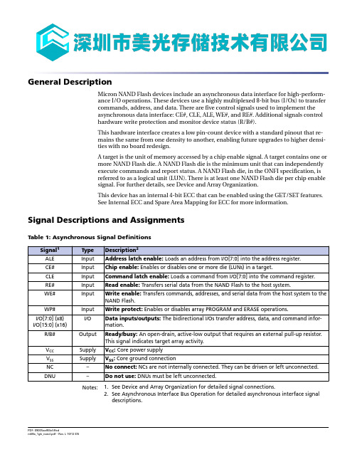
General DescriptionMicron NAND Flash devices include an asynchronous data interface for high-perform-ance I/O operations. These devices use a highly multiplexed 8-bit bus (I/Ox) to transfercommands, address, and data. There are five control signals used to implement theasynchronous data interface: CE#, CLE, ALE, WE#, and RE#. Additional signals controlhardware write protection and monitor device status (R/B#).This hardware interface creates a low pin-count device with a standard pinout that re-mains the same from one density to another, enabling future upgrades to higher densi-ties with no board redesign.A target is the unit of memory accessed by a chip enable signal. A target contains one ormore NAND Flash die. A NAND Flash die is the minimum unit that can independentlyexecute commands and report status. A NAND Flash die, in the ONFI specification, isreferred to as a logical unit (LUN). There is at least one NAND Flash die per chip enablesignal. For further details, see Device and Array Organization.This device has an internal 4-bit ECC that can be enabled using the GET/SET features.See Internal ECC and Spare Area Mapping for ECC for more information.Signal Descriptions and AssignmentsTable 1: Asynchronous Signal DefinitionsNotes: 1.See Device and Array Organization for detailed signal connections.2.See Asynchronous Interface Bus Operation for detailed asynchronous interface signaldescriptions.Electrical SpecificationsStresses greater than those listed can cause permanent damage to the device. This is astress rating only, and functional operation of the device at these or any other condi-tions above those indicated in the operational sections of this specification is not guar-anteed. Exposure to absolute maximum rating conditions for extended periods can af-fect reliability.Table 16: Absolute Maximum RatingsTable 17: Recommended Operating ConditionsTable 18: Valid BlocksNote: 1.Invalid blocks are blocks that contain one or more bad bits. The device may contain badblocks upon shipment. Additional bad blocks may develop over time; however, the totalnumber of available blocks will not drop below NVB during the endurance life of thedevice. Do not erase or program blocks marked invalid by the factory.Table 19: CapacitanceNotes: 1.These parameters are verified in device characterization and are not 100% tested.2.Test conditions: T C = 25°C; f = 1 MHz; V IN = 0V.Table 20: Test ConditionsNote: 1.These parameters are verified in device characterization and are not 100% tested.Electrical Specifications – AC Characteristics and Operating Conditions Table 21: AC Characteristics: Command, Data, and Address Input (3.3V)Notes: 1.Operating mode timings meet ONFI timing mode 5 parameters.2.Timing for t ADL begins in the address cycle, on the final rising edge of WE#, and endswith the first rising edge of WE# for data input.Table 22: AC Characteristics: Command, Data, and Address Input (1.8V)Notes: 1.Operating mode timings meet ONFI timing mode 4 parameters.2.Timing for t ADL begins in the address cycle on the final rising edge of WE#, and endswith the first rising edge of WE# for data input.Table 23: AC Characteristics: Normal Operation (3.3V)Notes: 1.AC characteristics may need to be relaxed if I/O drive strength is not set to full.2.Transition is measured ±200mV from steady-state voltage with load. This parameter issampled and not 100% tested.3.The first time the RESET (FFh) command is issued while the device is idle, the device willgo busy for a maximum of 1ms. Thereafter, the device goes busy for a maximum of 5µs. Table 24: AC Characteristics: Normal Operation (1.8V)。
解读U盘存储结构原理

解读U盘存储结构原理U盘的结构比较简单,主要是由USB插头、主控芯片、稳压IC(LDO)、晶振、闪存(FLASH)、PCB板、帖片电阻、电容、发光二极管(LED)等组成。
U盘的结构基本上由五部分组成:USB端口、主控芯片、FLASH(闪存)芯片、PCB底板、外壳封装。
U盘的基本工作原理也比较简单:USB端口负责连接电脑,是数据输入或输出的通道;主控芯片负责各部件的协调管理和下达各项动作指令,并使计算机将U盘识别为“可移动磁盘”,是U 盘的“大脑”;FLASH芯片与电脑中内存条的原理基本相同,是保存数据的实体,其特点是断电后数据不会丢失,能长期保存;PCB底板是负责提供相应处理数据平台,且将各部件连接在一起。
概要: 所谓“USB闪存盘”(以下简称“U盘”)是基于USB接口、以闪存芯片为存储介质的无需驱动器的新一代存储设备。
U盘的出现是移动存储技术领域的一大突破,其体积小巧,特别适合随身携带,可以随时随地、轻松交换资料数据,是理想的移动办公及数据存储交换产品。
U盘的结构比较简单,主要是由USB插头、主控芯片、稳压IC(LDO)、晶振、闪存(FLASH)、PCB板、帖片电阻、电容、发光二极管(LED)等组成。
U盘使用标准的USB接口,容量一般在32M~256M之间,最高容量已有2G的产品,能够在各种主流操作系统及硬件平台之间作大容量数据存储及交换。
其低端产品的市场价格已与软驱接近,而且现在很多主板已支持从USB存储器启动,实用功能更强。
总体来说U盘有着软驱不可比拟的优势,主要具有体积小、功能齐全、使用安全可靠等特点。
但也存在容量还不够大且无法扩充、价格较高、在Win98等部分操作系统下需安装驱动程序等缺点。
USB插头:容易出现和电路板虚焊,造成U盘无法被电脑识别,如果是电源脚虚焊,会使U盘插上电脑无任何反映。
有时将U盘摇动一下电脑上又可以识别,就可以判断USB插口接触不良。
只要将其补焊即可解决问题。
稳压IC:又称LDO,其输入端5V,输出3V,有些劣质U盘的稳压IC很小,容易过热而烧毁。
- 1、下载文档前请自行甄别文档内容的完整性,平台不提供额外的编辑、内容补充、找答案等附加服务。
- 2、"仅部分预览"的文档,不可在线预览部分如存在完整性等问题,可反馈申请退款(可完整预览的文档不适用该条件!)。
- 3、如文档侵犯您的权益,请联系客服反馈,我们会尽快为您处理(人工客服工作时间:9:00-18:30)。
NAND Flash MemoryMT29F1G08ABADAWP, MT29F1G08ABBDAH4, MT29F1G08ABBDAHC, MT29F1G16ABBDAH4, MT29F1G16ABBDAHC, MT29F1G08ABADAH4Features•Open NAND Flash Interface (ONFI) 1.0-compliant1•Single-level cell (SLC) technology•Organization–Page size x8: 2112 bytes (2048 + 64 bytes)–Page size x16: 1056 words (1024 + 32 words)–Block size: 64 pages (128K + 4K bytes)–Device size: 1Gb: 1024 blocks •Asynchronous I/O performance–t RC/t WC: 20ns (3.3V), 25ns (1.8V)•Array performance–Read page: 25µs3–Program page: 200µs (TYP, 3.3V and 1.8V)3–Erase block: 700µs (TYP)•Command set: ONFI NAND Flash Protocol •Advanced command set–Program page cache mode5–Read page cache mode5–One-time programmable (OTP) mode–Read unique ID–Internal data move•Operation status byte provides software method for detecting–Operation completion–Pass/fail condition–Write-protect status•Internal data move operations supported within the device from which data is read •Ready/busy# (R/B#) signal provides a hardware method for detecting operation completion•WP# signal: write protect entire device•First block (block address 00h) is valid when ship-ped from factory with ECC. For minimum required ECC, see Error Management.•Block 0 requires 1-bit ECC if PROGRAM/ERASE cy-cles are less than 1000•RESET (FFh) required as first command after pow-er-on•Alternate method of device initialization (Nand_In-it) after power up4 (contact factory)•Quality and reliability–Data retention: 10 years–Endurance: 100,000 PROGRAM/ERASE cycles •Operating Voltage Range–V CC: 2.7–3.6V–V CC: 1.7–1.95V•Operating temperature:–Commercial: 0°C to +70°C–Extended (ET): –40ºC to +85ºC•Package–48-pin TSOP type 1, CPL2–63-ball VFBGANotes: 1.The ONFI 1.0 specification is available at.2.CPL = Center parting line.3.See Electrical Specifications for t R_ECC andt PROG_ECC specifications.4.Available only in the 1.8V VFBGA package.5.Supported only with ECC disabled.Part Numbering InformationMicron NAND Flash devices are available in different configurations and densities. Verify valid part numbers by using Micron’s part catalog search at . To compare features and specifications by device type, visit /products. Contact the factory for devices not found.Figure 1: Marketing Part Number ChartM T 29F 1G 08 A B B D A HC IT ES :DMicron TechnologyProduct Family29F = NAND Flash memoryDensity1G = 1GbDevice Width08 = 8-bit16 = 16-bitLevelA= SLCClassificationMark Die nCE RnB I/O Channels B 1 1 1 1Operating Voltage RangeA = 3.3V (2.7–3.6V)B = 1.8V (1.7–1.95V)Feature SetD = Feature set D Production StatusBlank = ProductionES = Engineering sampleMS = Mechanical sampleQS = Qualification sampleSpecial OptionsBlankOperating Temperature Range Blank = Commercial (0°C to +70°C)IT = Industrial (–40°C to +85°C)Speed GradeBlankPackage CodeWP = 48-pin TSOP 1HC = 63-ball VFBGA (10.5 x 13 x 1.0mm) H4 = 63-ball VFBGA (9 x 11 x 1.0mm)InterfaceA = Async onlyX = Premium lifecycle product (PLP)ContentsGeneral Description (8)Signal Descriptions and Assignments (8)Signal Assignments (9)Package Dimensions (12)Architecture (15)Device and Array Organization (16)Asynchronous Interface Bus Operation (18)Asynchronous Enable/Standby (18)Asynchronous Commands (18)Asynchronous Addresses (20)Asynchronous Data Input (21)Asynchronous Data Output (22)Write Protect# (23)Ready/Busy# (23)Device Initialization (28)Command Definitions (29)Reset Operations (31)RESET (FFh) (31)Identification Operations (32)READ ID (90h) (32)READ ID Parameter Tables (33)READ PARAMETER PAGE (ECh) (35)Parameter Page Data Structure Tables (36)READ UNIQUE ID (EDh) (39)Feature Operations (40)SET FEATURES (EFh) (41)GET FEATURES (EEh) (42)Status Operations (45)READ STATUS (70h) (46)Column Address Operations (47)RANDOM DATA READ (05h-E0h) (47)RANDOM DATA INPUT (85h) (48)PROGRAM FOR INTERNAL DATA INPUT (85h) (48)Read Operations (50)READ MODE (00h) (51)READ PAGE (00h-30h) (51)READ PAGE CACHE SEQUENTIAL (31h) (52)READ PAGE CACHE RANDOM (00h-31h) (53)READ PAGE CACHE LAST (3Fh) (55)Program Operations (56)PROGRAM PAGE (80h-10h) (56)PROGRAM PAGE CACHE (80h-15h) (57)Erase Operations (59)ERASE BLOCK (60h-D0h) (59)Internal Data Move Operations (60)READ FOR INTERNAL DATA MOVE (00h-35h) (60)PROGRAM FOR INTERNAL DATA MOVE (85h–10h) (63)One-Time Programmable (OTP) Operations (64)OTP DATA PROGRAM (80h-10h) (65)RANDOM DATA INPUT (85h) (66)OTP DATA PROTECT (80h-10) (67)OTP DATA READ (00h-30h) (69)Error Management (71)Internal ECC and Spare Area Mapping for ECC (73)Electrical Specifications (75)Electrical Specifications – AC Characteristics and Operating Conditions (77)Electrical Specifications – DC Characteristics and Operating Conditions (80)Electrical Specifications – Program/Erase Characteristics (82)Asynchronous Interface Timing Diagrams (83)Revision History (93)Rev. O – 03/14 (93)Rev. N – 01/14 (93)Rev. M – 07/13 (93)Rev. L – 10/12 (93)Rev. K – 02/12 (93)Rev. J – 12/11 (93)Rev. I – 11/11 (93)Rev. H – 09/11 (93)Rev. G – 01/11 (93)Rev. F – 12/10 (93)Rev. E – 11/10 (93)Rev. D – 06/10 (94)Rev C – 04/10 (94)Rev B – 03/10 (94)Rev A – 02/10 (94)List of TablesTable 1: Asynchronous Signal Definitions (8)Table 2: Array Addressing (x8) (16)Table 3: Array Addressing (x16) (17)Table 4: Asynchronous Interface Mode Selection (18)Table 5: Command Set (29)Table 6: READ ID Parameters for Address 00h (33)Table 7: READ ID Parameters for Address 20h (34)Table 8: Parameter Page Data Structure (36)Table 9: Feature Address Definitions (40)Table 10: Feature Address 90h – Array Operation Mode (41)Table 11: Feature Addresses 01h: Timing Mode (43)Table 12: Feature Addresses 80h: Programmable I/O Drive Strength (44)Table 13: Feature Addresses 81h: Programmable R/B# Pull-Down Strength (44)Table 14: Status Register Definition (45)Table 15: Error Management Details (71)Table 16: Absolute Maximum Ratings (75)Table 17: Recommended Operating Conditions (75)Table 18: Valid Blocks (75)Table 19: Capacitance (76)Table 20: Test Conditions (76)Table 21: AC Characteristics: Command, Data, and Address Input (3.3V) (77)Table 22: AC Characteristics: Command, Data, and Address Input (1.8V) (77)Table 23: AC Characteristics: Normal Operation (3.3V) (78)Table 24: AC Characteristics: Normal Operation (1.8V) (78)Table 25: DC Characteristics and Operating Conditions (3.3V) (80)Table 26: DC Characteristics and Operating Conditions (1.8V) (81)Table 27: ProgramErase Characteristics (82)List of FiguresFigure 1: Marketing Part Number Chart (2)Figure 2: 48-Pin TSOP – Type 1, CPL (Top View) (9)Figure 3: 63-Ball VFBGA, x8 (Balls Down, Top View) (10)Figure 4: 63-Ball VFBGA, x16 (Balls Down, Top View) (11)Figure 5: 48-Pin TSOP – Type 1, CPL (12)Figure 6: 63-Ball VFBGA (HC) (13)Figure 7: 63-Ball VFBGA (H4) 9mm x 11mm (14)Figure 8: NAND Flash Die (LUN) Functional Block Diagram (15)Figure 9: Array Organization – x8 (16)Figure 10: Array Organization – x16 (17)Figure 11: Asynchronous Command Latch Cycle (19)Figure 12: Asynchronous Address Latch Cycle (20)Figure 13: Asynchronous Data Input Cycles (21)Figure 14: Asynchronous Data Output Cycles (22)Figure 15: Asynchronous Data Output Cycles (EDO Mode) (23)Figure 16: READ/BUSY# Open Drain (24)Figure 17: t Fall and t Rise (3.3V V CC) (25)Figure 18: t Fall and t Rise (1.8V V CC) (25)Figure 19: I OL vs. Rp (V CC = 3.3V V CC) (26)Figure 20: I OL vs. Rp (1.8V V CC) (26)Figure 21: TC vs. Rp (27)Figure 22: R/B# Power-On Behavior (28)Figure 23: RESET (FFh) Operation (31)Figure 24: READ ID (90h) with 00h Address Operation (32)Figure 25: READ ID (90h) with 20h Address Operation (32)Figure 26: READ PARAMETER (ECh) Operation (35)Figure 27: READ UNIQUE ID (EDh) Operation (39)Figure 28: SET FEATURES (EFh) Operation (41)Figure 29: GET FEATURES (EEh) Operation (42)Figure 30: READ STATUS (70h) Operation (46)Figure 31: RANDOM DATA READ (05h-E0h) Operation (47)Figure 32: RANDOM DATA INPUT (85h) Operation (48)Figure 33: PROGRAM FOR INTERNAL DATA INPUT (85h) Operation (49)Figure 34: READ PAGE (00h-30h) Operation (52)Figure 35: READ PAGE (00h-30h) Operation with Internal ECC Enabled (52)Figure 36: READ PAGE CACHE SEQUENTIAL (31h) Operation (53)Figure 37: READ PAGE CACHE RANDOM (00h-31h) Operation (54)Figure 38: READ PAGE CACHE LAST (3Fh) Operation (55)Figure 39: PROGRAM PAGE (80h-10h) Operaton (57)Figure 40: PROGRAM PAGE CACHE (80h-15h) Operation (Start) (58)Figure 41: PROGRAM PAGE CACHE (80h-15h) Operation (End) (58)Figure 42: ERASE BLOCK (60h-D0h) Operation (59)Figure 43: READ FOR INTERNAL DATA MOVE (00h-35h) Operation (61)Figure 44: READ FOR INTERNAL DATA MOVE (00h–35h) with RANDOM DATA READ (05h–E0h) (61)Figure 45: INTERNAL DATA MOVE (85h-10h) with Internal ECC Enabled (62)Figure 46: INTERNAL DATA MOVE (85h-10h) with RANDOM DATA INPUT with Internal ECC Enabled (62)Figure 47: PROGRAM FOR INTERNAL DATA MOVE (85h–10h) Operation (63)Figure 48: PROGRAM FOR INTERNAL DATA MOVE (85h-10h) with RANDOM DATA INPUT (85h) (63)Figure 49: OTP DATA PROGRAM (After Entering OTP Operation Mode) (66)Figure 50: OTP DATA PROGRAM Operation with RANDOM DATA INPUT (After Entering OTP Operation Mode) (67)Figure 51: OTP DATA PROTECT Operation (After Entering OTP Protect Mode) (68)Figure 52: OTP DATA READ (69)Figure 53: OTP DATA READ with RANDOM DATA READ Operation (70)Figure 54: Spare Area Mapping (x8) (73)Figure 55: Spare Area Mapping (x16) (74)Figure 56: RESET Operation (83)Figure 57: READ STATUS Cycle (83)Figure 58: READ PARAMETER PAGE (84)Figure 59: READ PAGE (84)Figure 60: READ PAGE Operation with CE# “Don’t Care” (85)Figure 61: RANDOM DATA READ (86)Figure 62: READ PAGE CACHE SEQUENTIAL (87)Figure 63: READ PAGE CACHE RANDOM (88)Figure 64: READ ID Operation (89)Figure 65: PROGRAM PAGE Operation (89)Figure 66: PROGRAM PAGE Operation with CE# “Don’t Care” (90)Figure 67: PROGRAM PAGE Operation with RANDOM DATA INPUT (90)Figure 68: PROGRAM PAGE CACHE (91)Figure 69: PROGRAM PAGE CACHE Ending on 15h (91)Figure 70: INTERNAL DATA MOVE (92)Figure 71: ERASE BLOCK Operation (92)General DescriptionMicron NAND Flash devices include an asynchronous data interface for high-perform-ance I/O operations. These devices use a highly multiplexed 8-bit bus (I/Ox) to transfercommands, address, and data. There are five control signals used to implement theasynchronous data interface: CE#, CLE, ALE, WE#, and RE#. Additional signals controlhardware write protection and monitor device status (R/B#).This hardware interface creates a low pin-count device with a standard pinout that re-mains the same from one density to another, enabling future upgrades to higher densi-ties with no board redesign.A target is the unit of memory accessed by a chip enable signal. A target contains one ormore NAND Flash die. A NAND Flash die is the minimum unit that can independentlyexecute commands and report status. A NAND Flash die, in the ONFI specification, isreferred to as a logical unit (LUN). There is at least one NAND Flash die per chip enablesignal. For further details, see Device and Array Organization.This device has an internal 4-bit ECC that can be enabled using the GET/SET features.See Internal ECC and Spare Area Mapping for ECC for more information.Signal Descriptions and AssignmentsTable 1: Asynchronous Signal DefinitionsNotes: 1.See Device and Array Organization for detailed signal connections.2.See Asynchronous Interface Bus Operation for detailed asynchronous interface signaldescriptions.Signal AssignmentsFigure 2: 48-Pin TSOP – Type 1, CPL (Top View)x8NC NC NC NC NC NC R/B#RE#CE#NC NC Vcc Vss NC NC CLE ALE WE#WP#NC NC NC NC NCx16NC NC NC NC NC NC R/B#RE#CE#NC NC Vcc Vss NC NC CLE ALE WE#WP#NC NC NC NC NCx8Vss 1DNU NC NC I/O7I/O6I/O5I/O4NC Vcc 1DNU Vcc Vss NC Vcc 1NC I/O3I/O2I/O1I/O0NC NC NC Vss 1x16Vss I/O15I/O14I/O13I/O7I/O6I/O5I/O4I/O12Vcc DNU Vcc Vss NC Vcc I/O11I/O3I/O2I/O1I/O0I/O10I/O9I/O8VssNote:1.These pins might not be bonded in the package; however, Micron recommends that thecustomer connect these pins to the designated external sources for ONFI compatibility.Figure 3: 63-Ball VFBGA, x8 (Balls Down, Top View)Note: 1.These pins might not be bonded inthe package; however, Micron recommends that thecustomer connect these pins to the designated external sources for ONFI compatibility.Figure 4: 63-Ball VFBGA, x16 (Balls Down, Top View)Package Dimensions Figure 5: 48-Pin TSOP – Type 1, CPLDetail AGageplane0.50 TYPfor referenceonlyNote: 1.All dimensions are in millimeters.Figure 6: 63-Ball VFBGA (HC)ball pads.Note: 1.All dimensions are in millimeters.Figure 7: 63-Ball VFBGA (H4) 9mm x 11mm1.0 MAX Note: 1.All dimensions are in millimeters.ArchitectureThese devices use NAND Flash electrical and command interfaces. Data, commands,and addresses are multiplexed onto the same pins and received by I/O control circuits.The commands received at the I/O control circuits are latched by a command registerand are transferred to control logic circuits for generating internal signals to control de-vice operations. The addresses are latched by an address register and sent to a row de-coder to select a row address, or to a column decoder to select a column address.Data is transferred to or from the NAND Flash memory array, byte by byte (x8) or wordby word (x16), through a data register and a cache register.The NAND Flash memory array is programmed and read using page-based operationsand is erased using block-based operations. During normal page operations, the dataand cache registers act as a single register. During cache operations, the data and cacheregisters operate independently to increase data throughput. The status register reportsthe status of die operations.Figure 8: NAND Flash Die (LUN) Functional Block DiagramDevice and Array Organization Figure 9: Array Organization – x8Cache Register Data Register1024 blocksper device2112 bytes= 1 block(128K + 4K) bytes= (2K + 64) bytes= (2K + 64) bytes x 64 pages= (128K + 4K) bytes= (2K + 64) bytes x 64 pagesx 1024 blocks= 1056MbTable 2: Array Addressing (x8)Notes: 1.If CA11 is 1, then CA[10:6] must be 0.2.Block address concatenated with page address = actual page address; CAx = column ad-dress; PAx = page address; BAx = block address.Figure 10: Array Organization – x16Cache Register Data Register1024 blocksper device1056 words= 1 block(64K + 2K) words= (1K + 32) words= (1K + 32) words x 64 pages= (64K + 2K) words= (1K + 32) words x 64 pagesx 1024 blocks= 1056MbTable 3: Array Addressing (x16)Notes: 1.If CA10 is 1, then CA[9:5] must be 0.2.Block address concatenated with page address = actual page address. CAx = column ad-dress; PAx = page address; BAx = block address.3.I/O[15:8] are not used during the addressing sequence and should be driven LOW.Asynchronous Interface Bus OperationThe bus on the device is multiplexed. Data I/O, addresses, and commands all share thesame pins. I/O[15:8] are used only for data in the x16 configuration. Addresses andcommands are always supplied on I/O[7:0].The command sequence typically consists of a COMMAND LATCH cycle, address inputcycles, and one or more data cycles, either READ or WRITE.Table 4: Asynchronous Interface Mode SelectionNotes: 1.Mode selection settings for this table: H = Logic level HIGH; L = Logic level LOW; X = V IHor V IL.2.WP# should be biased to CMOS LOW or HIGH for standby.Asynchronous Enable/StandbyWhen the device is not performing an operation, the CE# pin is typically driven HIGHand the device enters standby mode. The memory will enter standby if CE# goes HIGHwhile data is being transferred and the device is not busy. This helps reduce power con-sumption.The CE# “Don’t Care” operation enables the NAND Flash to reside on the same asyn-chronous memory bus as other Flash or SRAM devices. Other devices on the memorybus can then be accessed while the NAND Flash is busy with internal operations. Thiscapability is important for designs that require multiple NAND Flash devices on thesame bus.A HIGH CLE signal indicates that a command cycle is taking place. A HIGH ALE signalsignifies that an ADDRESS INPUT cycle is occurring.Asynchronous CommandsAn asynchronous command is written from I/O[7:0] to the command register on the ris-ing edge of WE# when CE# is LOW, ALE is LOW, CLE is HIGH, and RE# is HIGH.Commands are typically ignored by die (LUNs) that are busy (RDY = 0); however, somecommands, including READ STATUS (70h), are accepted by die (LUNs) even when theyare busy.For devices with a x16 interface, I/O[15:8] must be written with zeros when a commandis issued.Figure 11: Asynchronous Command Latch CycleWE#CE#ALECLEI/OxDon’t CareAsynchronous AddressesAn asynchronous address is written from I/O[7:0] to the address register on the risingedge of WE# when CE# is LOW, ALE is HIGH, CLE is LOW, and RE# is HIGH.Bits that are not part of the address space must be LOW (see Device and Array Organiza-tion). The number of cycles required for each command varies. Refer to the commanddescriptions to determine addressing requirements.Addresses are input on I/O[7:0] on x8 devices and on I/O[15:0] on x16 devices.Figure 12: Asynchronous Address Latch CycleWE#CE#ALECLEI/OxDon’t Care UndefinedAsynchronous Data InputData is written to the cache register of the selected die (LUN) on the rising edge of WE#when CE# is LOW, ALE is LOW, CLE is LOW, and RE# is HIGH.Data input is ignored by die (LUNs) that are not selected or are busy (RDY = 0). Data is written to the data register on the rising edge of WE# when CE#, CLE, and ALE are LOW,and the device is not busy.Data is input on I/O[7:0] on x8 devices and on I/O[15:0] on x16 devices.Figure 13: Asynchronous Data Input CyclesWE#CE#ALECLEI/OxDon’t CareAsynchronous Data OutputData can be output from a die (LUN) if it is in a READY state. Data output is supportedfollowing a READ operation from the NAND Flash array. Data is output from the cacheregister of the selected die (LUN) on the falling edge of RE# when CE# is LOW, ALE isLOW, CLE is LOW, and WE# is HIGH.If the host controller is using a t RC of 30ns or greater, the host can latch the data on therising edge of RE# (see the figure below for proper timing). If the host controller is usinga t RC of less than 30ns, the host can latch the data on the next falling edge of RE#.Data is output on I/O[7:0] on x8 devices and on I/O[15:0] on x16 devices.Figure 14: Asynchronous Data Output CyclesCE# RE# I/OxRDYFigure 15: Asynchronous Data Output Cycles (EDO Mode)RE#I/OxRDYWrite Protect#The write protect# (WP#) signal enables or disables PROGRAM and ERASE operationsto a target. When WP# is LOW, PROGRAM and ERASE operations are disabled. WhenWP# is HIGH, PROGRAM and ERASE operations are enabled.It is recommended that the host drive WP# LOW during power-on until V CC is stable toprevent inadvertent PROGRAM and ERASE operations (see Device Initialization for ad-ditional details).WP# must be transitioned only when the target is not busy and prior to beginning acommand sequence. After a command sequence is complete and the target is ready,WP# can be transitioned. After WP# is transitioned, the host must wait t WW before issu-ing a new command.The WP# signal is always an active input, even when CE# is HIGH. This signal shouldnot be multiplexed with other signals.Ready/Busy#The ready/busy# (R/B#) signal provides a hardware method of indicating whether a tar-get is ready or busy. A target is busy when one or more of its die (LUNs) are busy(RDY = 0). A target is ready when all of its die (LUNs) are ready (RDY = 1). Because eachdie (LUN) contains a status register, it is possible to determine the independent statusof each die (LUN) by polling its status register instead of using the R/B# signal (see Sta-tus Operations for details regarding die (LUN) status).This signal requires a pull-up resistor, Rp, for proper operation. R/B# is HIGH when thetarget is ready, and transitions LOW when the target is busy. The signal's open-draindriver enables multiple R/B# outputs to be OR-tied. Typically, R/B# is connected to an interrupt pin on the system controller.The combination of Rp and capacitive loading of the R/B# circuit determines the rise time of the R/B# signal. The actual value used for Rp depends on the system timing re-quirements. Large values of Rp cause R/B# to be delayed significantly. Between the 10% and 90% points on the R/B# waveform, the rise time is approximately two time con-stants (TC).T C = R × CWhere R = Rp (resistance of pull-up resistor), and C = total capacitive load.The fall time of the R/B# signal is determined mainly by the output impedance of theR/B# signal and the total load capacitance. Approximate Rp values using a circuit load of 100pF are provided in Figure 21 (page 27).The minimum value for Rp is determined by the output drive capability of the R/B# sig-nal, the output voltage swing, and V CC.Rp =V CC (MAX) - V OL (MAX)I OL + ΣILWhere ΣIL is the sum of the input currents of all devices tied to the R/B# pin. Figure 16: READ/BUSY# Open DrainFigure 17: t Fall and t Rise (3.3V V CC )3.503.002.502.001.501.000.500.00V CC 3.3VT CV Notes:1.t Fall and t Rise calculated at 10% and 90% points.2.t Rise dependent on external capacitance and resistive loading and output transistor im-pedance.3.t Rise primarily dependent on external pull-up resistor and external capacitive loading.4.t Fall = 10ns at 3.3V.5.See TC values in Figure 21 (page 27) for approximate Rp value and TC.Figure 18: t Fall and t Rise (1.8V V CC )3.503.002.502.001.501.000.500.00-124246T CV Notes:1.t Fall and t Rise are calculated at 10% and 90% points.2.t Rise is primarily dependent on external pull-up resistor and external capacitive loading.3.t Fall ≈ 7ns at 1.8V.4.See TC values in Figure 21 (page 27) for TC and approximate Rp value.Figure 19: I OL vs. Rp (V CC = 3.3V V CC )3.503.002.502.001.501.000.500.00Rp (Ω)I (mA)Figure 20: I OL vs. Rp (1.8V V CC )3.503.002.502.001.501.000.500.00Rp (Ω)I (mA)Figure 21: TC vs. RpI OL at V CC (MAX)RC = TC C = 100pFRp (Ω)T(ns)Device InitializationMicron NAND Flash devices are designed to prevent data corruption during power transitions. V CC is internally monitored. (The WP# signal supports additional hardware protection during power transitions.) When ramping V CC , use the following procedure to initialize the device:1.Ramp V CC .2.The host must wait for R/B# to be valid and HIGH before issuing RESET (FFh) to any target. The R/B# signal becomes valid when 50µs has elapsed since the begin-ning the V CC ramp, and 10µs has elapsed since V CC reaches V CC (MIN).3.If not monitoring R/B#, the host must wait at least 100µs after V CC reaches V CC(MIN). If monitoring R/B#, the host must wait until R/B# is HIGH.4.The asynchronous interface is active by default for each target. Each LUN draws less than an average of 10mA (I ST ) measured over intervals of 1ms until the RESET (FFh) command is issued.5.6.The device is now initialized and ready for normal operation.Figure 22: R/B# Power-On Behavioris issued InvalidCC startsV CCR/B#Command Definitions Table 5: Command SetTable 5: Command Set (Continued)Notes: 1.Busy means RDY = 0.2.Do not cross plane address boundaries when using READ for INTERNAL DATA MOVE andPROGRAM for INTERNAL DATA MOVE.3.These commands supported only with ECC disabled.4.Issuing a READ PAGE CACHE series (31h, 00h-31h, 3Fh) command when the array is busy(RDY = 1, ARDY = 0) is supported if the previous command was a READ PAGE (00h-30h)or READ PAGE CACHE series command; otherwise, it is prohibited.5.Issuing a PROGRAM PAGE CACHE (80h-15h) command when the array is busy (RDY = 1,ARDY = 0) is supported if the previous command was a PROGRAM PAGE CACHE(80h-15h) command; otherwise, it is prohibited.6.OTP commands can be entered only after issuing the SET FEATURES command with thefeature address.Reset OperationsRESET (FFh)The RESET command is used to put the memory device into a known condition and toabort the command sequence in progress.READ, PROGRAM, and ERASE commands can be aborted while the device is in the busystate. The contents of the memory location being programmed or the block beingerased are no longer valid. The data may be partially erased or programmed, and is in-valid. The command register is cleared and is ready for the next command. The dataThe status register contains the value E0h when WP# is HIGH; otherwise it is writtenwith a 60h value. R/B# goes LOW for t RST after the RESET command is written to thecommand register.The RESET command must be issued to all CE#s as the first command after power-on. Figure 23: RESET (FFh) OperationCycle typeI/O[7:0]R/B#Identification OperationsREAD ID (90h)The READ ID (90h) command is used to read identifier codes programmed into the tar-get. This command is accepted by the target only when all die (LUNs) on the target are idle.Writing 90h to the command register puts the target in read ID mode. The target stays in this mode until another valid command is issued.When the 90h command is followed by an 00h address cycle, the target returns a 5-byte identifier code that includes the manufacturer ID, device configuration, and part-spe-cific information.When the 90h command is followed by a 20h address cycle, the target returns the 4-byte ONFI identifier code.Figure 24: READ ID (90h) with 00h Address OperationCycle typeI/O[7:0]Note: 1.See the READ ID Parameter tables for byte definitions.Figure 25: READ ID (90h) with 20h Address OperationCycle typeI/O[7:0]Note: 1.See READ ID Parameter tables for byte definitions.READ ID Parameter TablesTable 6: READ ID Parameters for Address 00hTable 6: READ ID Parameters for Address 00h (Continued)Table 7: READ ID Parameters for Address 20hREAD PARAMETER PAGE (ECh)The READ PARAMETER PAGE (ECh) command is used to read the ONFI parameter pageprogrammed into the target. This command is accepted by the target only when all die(LUNs) on the target are idle.Writing ECh to the command register puts the target in read parameter page mode. Thetarget stays in this mode until another valid command is issued.When the ECh command is followed by an 00h address cycle, the target goes busy for t R.If the READ STATUS (70h) command is used to monitor for command completion, theREAD MODE (00h) command must be used to re-enable data output mode.A minimum of three copies of the parameter page are stored in the device. Each param-eter page is 256 bytes. If desired, the RANDOM DATA READ (05h-E0h) command can beused to change the location of data output.Figure 26: READ PARAMETER (ECh) OperationCycle type I/O[7:0]R/B#。