NI USB-6008简要说明
USB-6008 6009

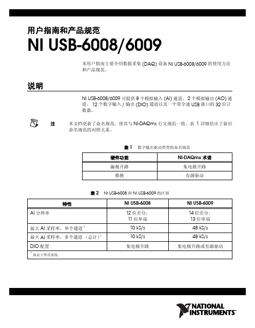
USER GUIDE AND SPECIFICATIONSUSB-6008/6009This guide describes how to use the National Instruments USB-6008/6009data acquisition (DAQ) devices and lists specifications. IntroductionThe NI USB-6008/6009 provides connection to eight analog input (AI)channels, two analog output (AO) channels, 12 digital input/output (DIO)channels, and a 32-bit counter with a full-speed USB interface.Note This manual revision updates naming conventions to reflect the conventions used inNI-DAQmx. Table1 notes the correlation between the old and updated names.Table 1. Digital Output Driver Type Naming ConventionsHardware Functionality NI-DAQmx TerminologyOpen-drain Open collectorPush-pull Active driveTable 2. Differences Between the USB-6008 and USB-6009Feature USB-6008USB-6009AI Resolution12 bits differential,11 bits single-ended 14 bits differential, 13 bits single-endedMaximum AI Sample Rate,Single Channel*10 kS/s48 kS/sMaximum AI Sample Rate,Multiple Channels (Aggregate)*10 kS/s42 kS/sDIO Configuration Open collector Open collector or active drive * Might be system dependent.USB-6008/6009 User Guide and Specifications 2Figure 1. USB-6008/6009Figure 2. USB-6008/6009 Back ViewSafety GuidelinesCautionOperate the hardware only as described in these operating instructions.The following section contains important safety information that you must follow when installing and using the USB-6008/6009.Do not operate the USB-6008/6009 in a manner not specified in thisdocument. Misuse of the device can result in a hazard. You can compromise the safety protection built into the device if the device is damaged in any way. If the device is damaged, contact National Instruments for repair.Do not substitute parts or modify the device except as described in this document. Use the device only with the chassis, modules, accessories, and cables specified in the installation instructions. You must have all covers and filler panels installed during operation of the device.Do not operate the device in an explosive atmosphere or where there maybe flammable gases or fumes. If you must operate the device in such anenvironment, it must be in a suitably rated enclosure.If you need to clean the device, use a dry cloth. Make sure that the deviceis completely dry and free from contaminants before returning it to service.Operate the device only at or below Pollution Degree 2. Pollution is foreignmatter in a solid, liquid, or gaseous state that can reduce dielectric strengthor surface resistivity. The following is a description of pollution degrees:•Pollution Degree 1 means no pollution or only dry, nonconductivepollution occurs. The pollution has no influence.•Pollution Degree 2 means that only nonconductive pollution occurs inmost cases. Occasionally, however, a temporary conductivity causedby condensation must be expected.•Pollution Degree 3 means that conductive pollution occurs, or dry,nonconductive pollution occurs that becomes conductive due tocondensation.You must insulate signal connections for the maximum voltage for whichthe device is rated. Do not exceed the maximum ratings for the device. Donot install wiring while the device is live with electrical signals. Do notremove or add connector blocks when power is connected to the system.Avoid contact between your body and the connector block signal when hotswapping modules. Remove power from signal lines before connectingthem to or disconnecting them from the device.Operate the device at or below the Measurement Category I1. Measurementcircuits are subjected to working voltages2 and transient stresses(overvoltage) from the circuit to which they are connected duringmeasurement or test. Measurement categories establish standard impulsewithstand voltage levels that commonly occur in electrical distributionsystems. The following is a description of measurement categories:•Measurement Category I is for measurements performed on circuitsnot directly connected to the electrical distribution system referred toas MAINS3 voltage. This category is for measurements of voltagesfrom specially protected secondary circuits. Such voltagemeasurements include signal levels, special equipment, limited-energyparts of equipment, circuits powered by regulated low-voltage sources,and electronics.1 Measurement Category as defined in electrical safety standard IEC 61010-1. Measurement Category is also referred to as Installation Category.2 Working V oltage is the highest rms value of an AC or DC voltage that can occur across any particular insulation.3 MAINS is defined as a hazardous live electrical supply system that powers equipment. Suitably rated measuring circuits may be connected to the MAINS for measuring purposes.© National Instruments Corporation3USB-6008/6009 User Guide and SpecificationsUSB-6008/6009 User Guide and Specifications •Measurement Category II is for measurements performed on circuits directly connected to the electrical distribution system. This category refers to local-level electrical distribution, such as that provided by a standard wall outlet (for example, 115 V for U.S. or 230 V for Europe). Examples of Measurement Category II are measurements performed on household appliances, portable tools, and similar E Series devices. •Measurement Category III is for measurements performed in the building installation at the distribution level. This category refers to measurements on hard-wired equipment such as equipment in fixed installations, distribution boards, and circuit breakers. Other examples are wiring, including cables, bus-bars, junction boxes, switches, socket-outlets in the fixed installation, and stationary motors with permanent connections to fixed installations.•Measurement Category IV is for measurements performed at the primary electrical supply installation (<1,000 V). Examples include electricity meters and measurements on primary overcurrent protection devices and on ripple control units.SoftwareSoftware support for the USB-6008/6009 for Windows 2000/XP is provided by NI-DAQmx.The NI-DAQmx CD contains example programs that you can use to get started programming with the USB-6008/6009. Refer to the NI-DAQmx for USB Devices Getting Started Guide , that shipped with your device and is also accessible from Start»All Programs»National Instruments»NI-DAQ for more information.Note For information about non-Windows operating system support, refer to /info and enter rddqld .VI LoggerThe NI-DAQmx CD includes VI Logger Lite which is an easy-to-use configuration-based tool specifically designed for data logging applications. The application is available at Start»All Programs»National Instruments»VI Logger.HardwareThe following block diagram shows key functional components of theUSB-6008/6009.Figure 3. Device Block Diagram© National Instruments Corporation5USB-6008/6009 User Guide and SpecificationsUSB-6008/6009 User Guide and Specifications 6Setting Up HardwareComplete the following steps to set up the hardware:1.Install combicon screw terminal blocks by inserting them into the combicon jacks.NoteThe USB-6008/6009 kit ships with signal labels. You can apply the signal labels to the screw terminal blocks for easy signal identification.2.Refer to Table 3 and Figure 4 for label orientation and affix the provided signal labels to the screw terminal blocks. Until the signal labels are applied, you can insert the screw terminal blocks into either of the combicon jacks. Refer to Figure 4 for more information about signal label orientation.Figure 4. Signal Label Application DiagramNoteOnce you label the screw terminal blocks, you must only insert them into thematching combicon jack, as indicated by the overlay label on the USB-6008/6009 device.3.Connect the wiring to the appropriate screw terminals.1Overlay Label with Pin Orientation Guides 2Combicon Jack 3Signal Labels 4USB CableI/O ConnectorThe USB-6008/6009 ships with one detachable screw terminal block foranalog signals and one detachable screw terminal block for digital signals.These terminal blocks provide 16 connections that use 16AWG to28AWG wire.Table3 lists the analog terminal assignments, and Table4 lists the digitalterminal assignments.Table 3. Analog Terminal Assignments© National Instruments Corporation7USB-6008/6009 User Guide and SpecificationsTable 4. Digital Terminal AssignmentsUSB-6008/6009 User Guide and Signal DescriptionsTable5 describes the signals available on the I/O connectors.Table 5. Signal DescriptionsSignal Name Reference Direction Description GND——Ground—The reference point for thesingle-ended AI measurements, biascurrent return point for differential modemeasurements, AO voltages, digitalsignals at the I/O connector, +5VDCsupply, and the +2.5VDC reference.AI <0..7>Varies Input Analog Input Channels 0 to 7—Forsingle-ended measurements, each signal isan analog input voltage channel. Fordifferential measurements, AI0and AI4are the positive and negative inputs ofdifferential analog input channel 0.The following signal pairs also formdifferential input channels:<AI 1, AI 5>, <AI2,AI 6>, and<AI3,AI7>.AO 0GND Output Analog Channel 0 Output—Supplies thevoltage output of AO channel 0.AO 1GND Output Analog Channel 1 Output—Supplies thevoltage output of AO channel 1.P1.<0..3> P0.<0..7>GND Input or Output Digital I/O Signals—You canindividually configure each signal as aninput or output.+2.5 V GND Output+2.5 V External Reference—Provides areference for wrap-back testing.+5 V GND Output+5 V Power Source—Provides +5Vpower up to 200mA.PFI 0GND Input PFI 0—This pin is configurable as either adigital trigger or an event counter input.© National Instruments Corporation9USB-6008/6009 User Guide and SpecificationsAnalog InputYou can connect analog input signals to the USB-6008/6009 through theI/O connector. Refer to Table5 for more information about connectinganalog input signals.Analog Input CircuitryFigure5 illustrates the analog input circuitry of the USB-6008/6009.Figure 5. Analog Input CircuitryMUXThe USB 6008/6009 has one analog-to-digital converter (ADC). Themultiplexer (MUX) routes one AI channel at a time to the PGA.PGAThe progammable-gain amplifier provides input gains of 1, 2, 4, 5, 8, 10,16, or 20 when configured for differential measurements and gain of1when configured for single-ended measurements. The PGA gain isautomatically calculated based on the voltage range selected in themeasurement application.A/D ConverterThe analog-to-digital converter (ADC) digitizes the AI signal byconverting the analog voltage into a digital code.USB-6008/6009 User Guide and AI FIFOThe USB-6008/6009 can perform both single and multiple A/Dconversions of a fixed or infinite number of samples. A first-in-first-out(FIFO) buffer holds data during AI acquisitions to ensure that no datais lost.Analog Input ModesYou can configure the AI channels on the USB-6008/6009 to takesingle-ended or differential measurements. Refer to Table5 for moreinformation about I/O connections for single-ended or differentialmeasurements.Connecting Differential Voltage SignalsFor differential signals, connect the positive lead of the signal to the AI+terminal, and the negative lead to the AI– terminal.Figure 6. Connecting a Differential Voltage SignalThe differential input mode can measure ±20 V signals in the ±20V range.However, the maximum voltage on any one pin is ±10 V with respect toGND. For example, if AI 1 is +10 V and AI 5 is –10 V, then themeasurement returned from the device is +20 V.Figure 7. Example of a Differential 20 V Measurement Connecting a signal greater than ±10 V on either pin results in a clipped output.Figure 8. Exceeding +10 V on AI Returns Clipped OutputConnecting Reference Single-Ended Voltage Signals To connect reference single-ended voltage signals (RSE) to theUSB-6008/6009, connect the positive voltage signal to the desiredAI terminal, and the ground signal to a GND terminal.Figure 9. Connecting a Reference Single-Ended Voltage SignalDigital TriggerWhen an AI task is defined, you can configure PFI 0 as a digital triggerinput. When the digital trigger is enabled, the AI task waits for a rising edgeon PFI 0 before starting the acquisition. To use ai/Start Trigger with adigital source, specify PFI 0 as the source and select rising edge. Analog OutputThe USB-6008/6009 has two independent AO channels that can generateoutputs from 0–5 V. All updates of AO lines are software-timed.Analog Output CircuitryFigure10 illustrates the analog output circuitry for the USB-6008/6009.Figure 10. Analog Output CircuitryDACsDigital-to-analog converts (DACs) convert digital codes to analogvoltages.Connecting Analog Output LoadsTo connect loads to the USB-6008/6009, connect the positive lead of theload to the AO terminal, and connect the ground of the load to a GNDterminal.Figure 11. Connecting a LoadMinimizing Glitches on the Output SignalWhen you use a DAC to generate a waveform, you may observe glitches inthe output signal. These glitches are normal; when a DAQ switches fromone voltage to another, it produces glitches due to released charges. Thelargest glitches occur when the most significant bit of the DAC codechanges. You can build a low-pass deglitching filter to remove some ofthese glitches, depending on the frequency and nature of the output signal.Refer to /support for more information about minimizingglitches.Digital I/OThe USB-6008/6009 has 12 digital lines, P0.<0..7> and P1.<0..3>, whichcomprise the DIO port. GND is the ground-reference signal for the DIOport. You can individually program all lines as inputs or outputs.Digital I/O CircuitryFigure12 shows P0.<0..7> connected to example signals configured asdigital inputs and digital outputs. You can configure P1.<0..3> similarly.Figure 12. Example of Connecting a LoadCautionExceeding the maximum input voltage ratings or maximum output ratings, which are listed in the Specifications , can damage the DAQ device and the computer. National Instruments is not liable for any damage resulting from such signal connections.Source/Sink InformationThe default configuration of the USB-6008/6009 DIO ports is opencollector, allowing 5 V operation, with an onboard 4.7 k Ω pull-up resistor.An external, user-provided, pull-up resistor can be added to increase thesource current drive up to a 8.5 mA limit per line as shown in Figure 13.The USB-6009 ports can also be configured as active drive using theDAQmx API, allowing 3.3 V operation with a source/sink current limit of± 8.5 mA. Refer to the NI-DAQmx Help for more information about how toset the DIO configuration.Figure 13. Example of Connecting External User-Provided ResistorComplete the following steps to determine the value of the user-providedpull-up resistor:1.Place an ammeter in series with the load.2.Place a variable resistor between the digital output line and the +5 V.3.Adjust the variable resistor until the ammeter current reads as theintended current. The intended current must be less than 8.5 mA.4.Remove the ammeter and variable resistor from your circuit.5.Measure the resistance of the variable resistor. The measuredresistance is the ideal value of the pull-up resistor.6.Select a static resistor value for your pull-up resistor that is greater thanor equal to the ideal resistance.7.Re-connect the load circuit and the pull-up resistor.I/O ProtectionTo protect the USB-6008/6009 against overvoltage, undervoltage, andovercurrent conditions, as well as ESD events, you should avoid these faultconditions by using the following guidelines:•If you configure a DIO line as an output, do not connect it to anyexternal signal source, ground signal, or power supply.•If you configure a DIO line as an output, understand the currentrequirements of the load connected to these signals. Do not exceed thespecified current output limits of the DAQ device.National Instruments has several signal conditioning solutions fordigital applications requiring high current drive.•If you configure a DIO line as an input, do not drive the line withvoltages outside of its normal operating range. The DIO lines have asmaller operating range than the AI signals.•Treat the DAQ device as you would treat any static sensitive device.Always properly ground yourself and the equipment when handlingthe DAQ device or connecting to it.Power-On StatesAt system startup and reset, the hardware sets all DIO lines tohigh-impedance inputs. The DAQ device does not drive the signal high orlow. Each line has a weak pull-up resistor connected to it.Static DIOEach of the USB-6008/6009 DIO lines can be used as a static DI or DOline. You can use static DIO lines to monitor or control digital signals. Allsamples of static DI lines and updates of DO lines are software-timed. Event CounterYou can configure PFI 0 as a source for a gated invertor counter input edgecount task. In this mode, falling-edge events are counted using a 32-bitcounter. For more information about event timing requirements, refer to theSpecifications section.Reference and Power SourcesThe USB-6008/6009 creates an external reference and supplies a powersource.+2.5 External ReferencesThe USB-6008/6009 creates a high-purity reference voltage supply forthe ADC using a multi-state regulator, amplifier, and filter circuit. Theresulting +2.5 V reference voltage can be used as a signal for self test.+5 V Power SourceThe USB-6008/6009 supplies a 5 V, 200 mA output. This source can beused to power external components.Note While the device is in USB suspend, the output is disabled.SpecificationsThe following specifications are typical at 25 °C, unless otherwise noted.Analog InputConverter type........................................Successive approximationAnalog inputs..........................................8 single-ended, 4 differential,software selectableInput resolutionUSB-6008........................................12 bits differential,11 bits single-endedUSB-6009........................................14 bits differential,13 bits single-endedMax sampling rate1Single channelUSB-6008.................................10 kS/sUSB-6009.................................48 kS/sMultiple channels (aggregate)USB-6008.................................10 kS/sUSB-6009.................................42 kS/sAI FIFO..................................................512 bytesTiming resolution...................................41.67 ns (24 MHz timebase)Timing accuracy.....................................100 ppm of actual sample rateInput rangeSingle-ended....................................±10 VDifferential......................................±20 V, ±10 V, ±5 V, ±4 V,±2.5V, ±2 V, ±1.25 V, ±1 VWorking voltage.....................................±10 VInput impedance.....................................144 kΩOvervoltage protection...........................±351 Might be system dependent.Trigger source........................................Software or external digitaltriggerSystem noiseUSB-6008, differential....................1.47 mVrmsUSB-6009, single-ended.................2.93 mVrmsUSB-6009, differential....................0.37 mVrmsUSB-6009, single-ended.................0.73 mVrmsAbsolute accuracy at full scale, single endedAbsolute accuracy at full scale, differential 1Analog OutputConverter type........................................Successive approximationAnalog outputs (2)Output resolution....................................12 bitsMaximum update rate............................150 Hz, software-timed Output range...........................................0 to +5 VOutput impedance..................................50 ΩRangeTypical at 25 °C (mV)Maximum over Temperature (mV)+1014.7138RangeTypical at 25 °C (mV)Maximum over Temperature (mV)+2014.7138+107.7384.8+54.2858.4+43.5953.1+2.52.5645.1+22.2142.5+1.251.7038.9+1 1.5337.51 Input voltages may not exceed the working voltage range.Output current drive................................5 mAPower-on state........................................0 VSlew rate.................................................1 V/µsShort circuit current................................50 mAAbsolute accuracy (no load)...................7 mV typical, 36.4 mV maximumat full scaleDigital I/ODigital I/OP0.<0..7>.........................................8 linesPI.<0..3>..........................................4 linesDirection control.....................................Each channel individuallyprogrammable as input or outputOutput driver typeUSB-6008........................................Open collector (open-drain)USB-6009........................................Each channel individuallyprogrammable as active drive(push-pull) or open collector(open-drain)Compatibility..........................................TTL, LVTTL, CMOSAbsolute maximum voltage range..........–0.5 to 5.8 V with respect to GNDPull-up resistor........................................4.7 kΩ to 5 VPower-on state........................................Input (high impedance)© National Instruments Corporation 21USB-6008/6009 User Guide and SpecificationsDigital logic levelsExternal Voltage+5 V output (200 mA maximum)..........+5 V typical, +4.85 V minimum+2.5 V output (1 mA maximum)...........+2.5 V typical+2.5 V accuracy.....................................0.25% maxReference temperature drift ...................50 ppm/°C maxCounterNumber of counters (1)Resolution..............................................32 bitsCounter measurements...........................Edge counting (falling-edge)Pull-up resistor.......................................4.7 k Ω to 5 VMaximum input frequency.....................5 MHzMinimum high pulse width....................100 nsMinimum low pulse width.....................100 nsInput high voltage..................................2.0 VInput low voltage ...................................0.8 VBus InterfaceUSB specification B 2.0 full-speedUSB bus speed.......................................12 Mb/s LevelMin Max Units Input low voltageInput high voltageInput leakage current–0.32.0—0.85.850V V µA Output low voltage (I = 8.5 mA)Output high voltageActive drive (push-pull), I = –8.5mAOpen collector (open-drain), I = –0.6mA, nominalOpen collector (open-drain), I = –8.5mA, with external pull-upresistor —2.02.02.00.83.55.0—V V V VPower RequirementsUSB4.10 to5.25 VDC.............................80 mA typical, 500 mA maxUSB suspend...................................300µA typical, 500µA maxPhysical CharacteristicsIf you need to clean the module, wipe it with a dry towel.DimensionsWithout connectors..........................6.35 cm × 8.51 cm × 2.31 cm(2.50 in. × 3.35 in. × 0.91 in.)With connectors...............................8.18 cm × 8.51 cm × 2.31 cm(3.22 in. × 3.35 in. × 0.91 in.)I/O B series B receptacle,(2)16position terminal blockplug headersWeightWith connectors...............................84 g (3 oz)Without connectors..........................54 g (21 oz)Screw-terminal wiring............................16 to 28 AWGTorque for screw terminals.....................0.22 to 0.25 N · m(2.0to2.2lb· in.)SafetyStandardsThe USB-6008/6009 is designed to meet the requirements of the followingstandards of safety for electrical equipment for measurement, control, andlaboratory use:•IEC 61010-1, EN 61010-1•UL 61010-1•CAN/CSA-C22.2 No. 61010-1/certification, search by model number or product line, and click theappropriate link in the Certification column.USB-6008/6009 User Guide and © National Instruments Corporation 23USB-6008/6009 User Guide and SpecificationsVoltagesConnect only voltages that are within these limits.Channel-to-GND ....................................±30V max,Measurement Category IMeasurement Category I is for measurements performed on circuits not directly connected to the electrical distribution system referred to asMAINS voltage. MAINS is a hazardous live electrical supply system that powers equipment. This category is for measurements of voltages fromspecially protected secondary circuits. Such voltage measurements include signal levels, special equipment, limited-energy parts of equipment,circuits powered by regulated low-voltage sources, and electronics.Caution Do not use this module for connection to signals or for measurements within Measurement Categories II, III, or IV .Hazardous LocationsThe USB-6008/6009 are not certified for use in hazardous locations.EnvironmentalThe USB-6008/6009 device is intended for indoor use only.Operating temperature(IEC 60068-2-1 and IEC 60068-2-2).....0 to 55 °COperating humidity(IEC 60068-2-56)...................................10 to 90% RH, noncondensingMaximum altitude..................................2,000 m (at 25°C ambienttemperature)Storage temperature(IEC 60068-2-1 and IEC 60068-2-2).....–40 to 85 °CStorage humidity(IEC 60068-2-56) ..................................5 to 90% RH, noncondensingPollution Degree (IEC 60664)...............2USB-6008/6009 User Guide and Specifications Electromagnetic CompatibilityEmissions................................................EN 55011 Class A at 10 mFCC Part 15A above 1 GHzImmunity ................................................Industrial levels perEN 61326:1997 + A2:2001,Table 1EMC/EMI...............................................CE, C-Tick, and FCC Part 15(Class A) CompliantNote The USB-6008/6009 may experience temporary variations in analog input readings when exposed to radiated and conducted RF noise. The device returns to normal operation after RF exposure is removed.CE ComplianceThis product meets the essential requirements of applicable EuropeanDirectives, as amended for CE marking, as follows:Low-Voltage Directive (safety)..............73/23/EECElectromagnetic CompatibilityDirective (EMC).....................................89/336/EECNoteRefer to the Declaration of Conformity (DoC) for this product for any additional regulatory compliance information. To obtain the DoC for this product, visit /certification , search by model number or product line, and click the appropriate link in the Certification column.Where to Go for SupportThe National Instruments Web site is your complete resource for technical support. At /support you have access to everything fromtroubleshooting and application development self-help resources to email and phone assistance from NI Application Engineers.A Declaration of Conformity (DoC) is our claim of compliance with the Council of the European Communities using the manufacturer’sdeclaration of conformity. This system affords the user protection forelectronic compatibility (EMC) and product safety. You can obtain the DoC for your product by visiting /certification . If your product supports calibration, you can obtain the calibration certificate for yourproduct at /calibration.。
NI USB-6001 6002 6003 OEM 用户指南说明书

USER GUIDENI USB-6001/6002/6003 OEM This document provides information about the dimensions, pinouts, connectors, LEDs, and mounting holes of the National Instruments USB-6001/6002/6003 OEM device.For more information about the device, refer to the NI USB-6001/6002/6003 User Guide and NI USB-6001Specifications, NI USB-6002 Specifications, and NI USB-6003 Specifications documents available at /manuals.Caution There are no product safety, electromagnetic compatibility (EMC), orCE marking compliance claims made for the NI USB-6001/6002/6003 OEMdevices.The NI USB-6001/6002/6003 OEM device is intended to be used as a component ofa larger system. National Instruments can help developers meet their compliancerequirements. The end product supplier, however, is responsible for conforming toany and all compliance requirements.Figure 1. USB-6001/6002/6003 OEM DeviceUSB-6001/6002/6003 OEM Device SpecificationsMost specifications of the USB-6001/6002/6003 OEM device are listed in the NI USB-6001, NI USB-6002, NI USB-6003 Specifications documents on /manuals. The following sections contain exceptions to the main specifications.Physical Characteristics Weight...............................................................31 g (1.10 oz) Dimensions.......................................................98 mm × 64 mm × 12 mm(3.90 in. × 2.50 in. × 0.50 in.)Figure 2. USB-6001/6002/6003 OEM Device Dimensions2||NI USB-6001/6002/6003 OEM User GuideI/O Connector PinoutsFigure3 shows the USB-6001/6002/6003 OEM device I/O connector pinouts.Figure 3. USB-6001/6002/6003 OEM T erminal AssignmentsSignal DescriptionsMost of the signals available on the I/O connector are described in the NI USB-6001/6002/6003 User Guide document available for download at /manuals. Table1 describes additional signals on the I/O connector of the OEM device.Table 1. Additional Signal DescriptionsSignal Name Reference Direction Description VBUS D GND Input USB PowerD+, D- D GND Input/Output USB Data LinesLED D GND Output Status LED DriverFor more information about USB signals, refer to the Universal Serial Bus Specification accessible at .NI USB-6001/6002/6003 OEM User Guide|© National Instruments|34| |NI USB-6001/6002/6003 OEM User GuideUsing the 34-Pin Connector with a Board Mount SocketThe USB-6001/6002/6003 OEM device can be mounted to a motherboard using the 34-pin connector, as shown in Figures 4 and 5.Figure 4. Mounting Using a 34-Pin ConnectorNoteRefer to the Device Components section for more information aboutmounting components.1Board Mount Socket 234-Pin Connector3USB-6001/6002/6003 OEM Device4Mounting Screw 5Mounting StandoffFigure 5. USB Device Installed on MotherboardConnecting to USBYou can use the USB connector on the USB-6001/6002/6003 OEM device to connect to the USB host. In this case, leave the D+ and D- signals and VBUS (on the 34-pin connector) unconnected.You can also use a USB connector on your motherboard to connect the USB-6001/6002/ 6003OEM device to the USB host through the 34-pin connector. In this case, do not connect to the USB connector on the USB-6001/6002/6003 OEM device.Using the Status LED DriverThe LED signal indicates the device status as listed in the NI USB-6001/6002/6003 User Guide document on /manuals. An open collector output drives the LED signal. For applications that use the LED signal, connect an external pull-up resistor from the LED signal to an external voltage.NI USB-6001/6002/6003 OEM User Guide|© National Instruments|56| |NI USB-6001/6002/6003 OEM User GuideTo drive a status LED, refer to the circuit as shown in Figure 6.Figure 6. To Drive a Status LEDTo use the LED signal to monitor the device state, refer to the circuit as shown in Figure 7.Figure 7. To Monitor Device State Through the LED SignalElectrical CharacteristicsTable 2 lists the LED electrical characteristics.Table 2. LED Electrical CharacteristicsParameter Condition Typical MaximumOutput Low V oltage I OL = 8 mA —0.4 V I OL = 18 mA1.2 V —External Pull-up V oltage —— 5.25 V Maximum Sinking Current——18 mADevice ComponentsTable3 lists the components used for interfacing and interacting with the USB-6001/6002/6003OEM device.Table 3. NI USB-6001/6002/6003 OEM Device ComponentsComponentReferenceDesignator(s)on PCB ManufacturerManufacturerPart NumberPartSpecificationsMicro USB connector J001Molex105164-0001—Hi-Speed USB cable,A to Micro-B, 1m—NI782909-01—Hi-Speed USB cable,A to Micro-B, 2m—NI782909-02—34-pin connector J0023M N2534-6V0C-RB-WF—34-pin mating connector —3M8534-4500PL(or equivalent)—Mounting Standoff Using34-pinboardmountsocket——— 4.76 mm (3/16 in.)HEX female-to-female, 15 mm(0.59 in.) longUsingribboncable——— 4.76 mm (3/16 in.)HEX female-to-female, 6.35 mm(1/4 in.) longScrew———M3 × 0.5,4-40 UNCNI USB-6001/6002/6003 OEM User Guide|© National Instruments|7Worldwide Support and ServicesThe National Instruments website is your complete resource for technical support. At / support you have access to everything from troubleshooting and application development self-help resources to email and phone assistance from NI Application Engineers.Visit /services for NI Factory Installation Services, repairs, extended warranty, and other services.Visit /register to register your National Instruments product. Product registration facilitates technical support and ensures that you receive important information updates from NI. National Instruments corporate headquarters is located at 11500 North Mopac Expressway, Austin, Texas, 78759-3504. National Instruments also has offices located around the world. For telephone support in the United States, create your service request at /support or dial 1866ASK MYNI(2756964). For telephone support outside the United States, visit the Worldwide Offices section of /niglobal to access the branch office websites, which provide up-to-date contact information, support phone numbers, email addresses, and current events.Refer to the NI Trademarks and Logo Guidelines at /trademarks for more information on National Instruments trademarks. Other product and company names mentioned herein are trademarks or trade names of their respective companies. For patents covering National Instruments products/technology, refer to the appropriate location: Help»Patents in your software, the patents.txt file on your media, or the National Instruments Patents Notice at /patents. You can find information about end-user license agreements (EULAs) and third-party legal notices in the readme file for your NI product. Refer to the Export Compliance Information at /legal/export-compliance for the National Instruments global trade compliance policy and how to obtain relevant HTS codes, ECCNs, and other import/export data. NI MAKES NO EXPRESS OR IMPLIED WARRANTIES AS TO THE ACCURACY OF THE INFORMATION CONTAINED HEREIN AND SHALL NOT BE LIABLE FOR ANY ERRORS. U.S. Government Customers: The data contained in this manual was developed at private expense and is subject to the applicable limited rights and restricted data rights as set forth in FAR 52.227-14, DFAR 252.227-7014, and DFAR 252.227-7015.© 2014 National Instruments. All rights reserved.374261A-01Aug14。
工控机实验报告
工业计算机控制实验报告实验一A/D、D/A 转换实验一、实验目的1.了解温控系统的组成。
2.了解NI 测量及自动化浏览器的使用并对数据采集卡进行设置。
3.了解Dasylab 软件的各项功能,并会简单的应用。
4.通过实验了解计算机是如何进行数据采集、控制的。
二、实验设备微型计算机、NI USB 6008 数据采集卡、温度控制仪、温箱。
三、实验内容1.了解温度控制系统的组成。
2.仔细观察老师对数据采集卡输入输出任务建立的过程及设置还有dasylab 基本功能的演示。
3.仔细阅读dasylab 相关文档,学习帮助文件tutorial 了解其基本使用方法。
4.动手实践,打开范例,仔细揣摩,并独立完成数据采集卡输入输出任务的建立并建立并运行单独的AD 及DA 系统,完成之后,按照自己的需要及兴趣搭建几个简单的系统运行。
四、温控系统的组成计算机温度控制系统由温度控制仪与计算机、数据采集卡一起构成,被控对象为温箱,温箱内装有电阻加热丝构成的电炉,还有模拟温度传感器AD590。
系统框图如图所示:五、温控仪基本工作原理温度控制仪由信号转换电路、电压放大电路、可控硅移相触发器及可控硅加热电路组成。
被控制的加热炉允许温度变化范围为0~100℃.集成电路温度传感器AD590(AD590 温数据采集卡温度控制仪温箱度传感器输出电流与绝对温度成正比关系,灵敏度为1uA/K).将炉温的变化转换为电流的变化送入信号转换、电压放大电路.信号转换电路将AD590 送来的电流信号转换为电压信号,然后经精密运算放大器放大、滤波后变为0~5V 的标准电压信号,一路送给炉温指示仪表,直接显示炉温值。
另一路送给微机接口电路供计算机采样.计算机通过插在计算机USB 总线接口上的NI USB 6008 12 位数据采集卡将传感器送来的0~5V 测量信号转换成0~FFFH 的12 位数字量信号,经与给定值比较,求出偏差值,然后对偏差值进行控制运算,得到控制度变化的输出量,再经过NI USB 6008 将该数字输出量经12 位D/A 转换器变为0~5V 的模拟电压信号送入可控硅移相触发器,触发器输出相应控制角的触发脉冲给可控硅,控制可控硅的导通与关断,从而达到控制炉温的目的。
NI推出高性价比、高精确度USB数据采集设备
NI推出高性价比、高精确度USB数据采集设备
佚名
【期刊名称】《世界仪表与自动化》
【年(卷),期】2005(009)003
【摘要】NI公司全新推出USB-6008和USB-6009即插即用式数据采集设备。
现在科学家、技术人员、工程师及学生们可以更低价位享受到全新NI数据采集硬件带来的高精确度数据采集。
这两款全新的USB数据采集设备将提供更小的尺寸和更强的连接性.成为数据记录、环境监测等应用的理想选择。
同时.该产品也适用高等院校教学.其合理的价格允许学生用户在实验室使用。
【总页数】1页(P11)
【正文语种】中文
【中图分类】TH714.7
【相关文献】
1.NI推出更高性价比的可应用于高性能USB数据采集的CompactDAQ机箱——NI cDAQ-9174和cDAQ-9178机箱为四槽和八槽机箱提供了更高效的混合传感器测试性能 [J], 无
2.NI推出高精度多功能USB接口数据采集设备——NIUSB-6281及USB-6289功能增强型18位分辨率设备 [J], 无
3.NI推出高性价比、高精度USB数据采集设备 [J], 薛紫薇
4.NI推出高性价比、高精度的USB数据采集设备 [J],
5.NI推出高精度多功能USB接口数据采集设备NIUSB-6281及USB-6289功能增强型18位分辨率设备 [J],
因版权原因,仅展示原文概要,查看原文内容请购买。
NI6008温度测量
基于PC的测控系统综合设计说明书题目:基于NIUSB6008DAQ卡的温度测量系统设计专业:测控技术与仪器班级: 10测控1班学号: 1010131113姓名:李栋指导教师:何涛吴庆华目录1.摘要 (3)1.1基本设计内容及要求 (3)2.硬件设计 (3)2.1原理框图 (3)2.2各主要部件及电路工作原理 (3)2.2.1温度采集 (3)2.2.2数据采集卡 (3)2. 2. 3 NI数采卡上提供了三种不同的终端模式 (4)2.2.4三种输入模式的优缺点比较 (5)3.软件设计 (6)3.1应用程序框图 (6)3.2前面板及程序图 (7)3.3标定程序 (7)3.3.1标定的选定 (7)3.4报警判断程序 (8)4.设计结果 (9)5.设计中遇到的问题以及体会 (10)6实物连线图 (10)7参考文献 (11)1摘要1.1基本设计内容及要求系统由PC 机、NIUSB6008DAQ 卡、温度传感器组成。
Lab VIEW 软件开发工具编写一个测试软件,实现对温度数据的采集、处理和显示。
要求:(1)人机界面显示采集的电压和对应的温度值,能人工手动设定温度上限和温度下线;(2)检测系统的标定中的斜率和截距能在人机界面中显示并能手动修改;(3)温度正常时,绿灯一直亮;温度不正常;报警红灯闪烁亮。
2硬件设计2.1总体设计原理框图2.2各主要电路及部件工作原理2.2.1温度采集温度传感器将外界温度变为模拟电流信号,经过变送器将模拟电流信号转变为模拟电压信号,在将模拟电压信号连接NIUSB6008DAQ 卡,对电压信号进行采集,将采集的数据输入到PC 机中,即可完成对数据的采集。
温度传感器选用的型号是STT-C1,STT-C 系列铂电阻温度传感器使用标准连接器,方便现场连接及维护,适用于医疗仪器、便携式仪表等温度的测量使用。
C1是圆形连接器。
温度范围-50~200℃。
与温读传感器配套使用温度变送器选用的型号是STWB-TR-X100T-R (-50~200℃)-FV2-P2-S0。
USB-6009用户使用手册
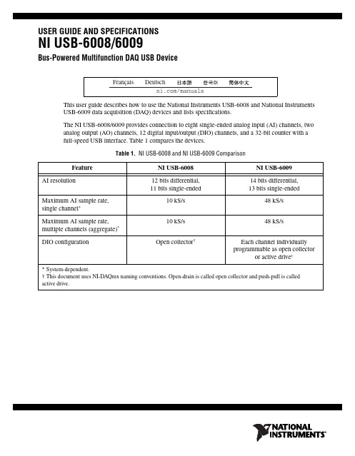
USER GUIDE AND SPECIFICATIONSNI USB-6008/6009Bus-Powered Multifunction DAQ USB DeviceThis user guide describes how to use the National Instruments USB-6008 and National Instruments USB-6009 data acquisition (DAQ) devices and lists specifications.The NI USB-6008/6009 provides connection to eight single-ended analog input (AI) channels, two analog output (AO) channels, 12 digital input/output (DIO) channels, and a 32-bit counter with afull-speed USB interface. Table1 compares the devices.Table 1. NI USB-6008 and NI USB-6009 ComparisonFeature NI USB-6008NI USB-6009AI resolution12 bits differential,11 bits single-ended 14 bits differential, 13 bits single-endedMaximum AI sample rate, single channel*10 kS/s48 kS/s Maximum AI sample rate,multiple channels (aggregate)*10 kS/s48 kS/sDIO configuration Open collector†Each channel individuallyprogrammable as open collectoror active drive†* System-dependent.† This document uses NI-DAQmx naming conventions. Open-drain is called open collector and push-pull is called active drive.Figure1 shows key functional components of the NI USB-6008/6009.Figure 1. NI USB-6008/6009 Block DiagramContentsSafety Guidelines (3)Electromagnetic Compatibility Guidelines (3)Unpacking (4)Setting Up the NI USB-6008/6009 (4)Using the NI USB-6008/6009 in an Application (6)Features (7)USB Connector and USB Cable Strain Relief (7)LED Indicator (8)Screw Terminal Connector Plugs (8)Firmware (8)Cables and Accessories (9)Pinout and Signal Descriptions (9)NI USB-6008/6009 User Guide and © National Instruments Corporation 3NI USB-6008/6009 User Guide and SpecificationsAnalog Input (11)Analog Input Modes and Signal Sources (11)Floating Signal Sources.......................................................................................................12Ground-Referenced Signal Sources.....................................................................................13Taking Differential Measurements......................................................................................14Taking Referenced Single-Ended Measurements................................................................15Digital Trigger.............................................................................................................................15Analog Output.. (16)Connecting Analog Output Loads...............................................................................................16Minimizing Glitches on the Output Signal..................................................................................16Digital I/O.. (17)Source/Sink Information..............................................................................................................18I/O Protection...............................................................................................................................19Power-On States..........................................................................................................................19Static DIO....................................................................................................................................19PFI 0.. (19)Using PFI 0 as a Digital Trigger..................................................................................................19Using PFI 0 as an Event Counter.................................................................................................19External Reference and Power Source. (20)+2.5V External Reference...........................................................................................................20+5 V Power Source......................................................................................................................20Specifications.......................................................................................................................................20Where to Go from Here.. (27)Example Programs.......................................................................................................................27Related Documentation................................................................................................................27Where to Go for Support (30)Safety GuidelinesOperate the NI USB-6008/6009 device only as described in this user guide.CautionDo not operate the NI USB-6008/6009 in a manner not specified in this document. Misuseof the device can result in a hazard. You can compromise the safety protection built into the device if the device is damaged in any way. If the device is damaged, contact National Instruments for repair.CautionDo not substitute parts or modify the device except as described in this document. Use thedevice only with the chassis, modules, accessories, and cables specified in the installation instructions. You must have all covers and filler panels installed during operation of the device.CautionDo not operate the device in an explosive atmosphere or where there may be flammablegases or fumes. If you must operate the device in such an environment, it must be in a suitably rated enclosure.Electromagnetic Compatibility GuidelinesThis product was tested and complies with the regulatory requirements and limits for electromagnetic compatibility (EMC) as stated in the product specifications. These requirements and limits are designed to provide reasonable protection against harmful interference when the product is operated in its intended operational electromagnetic environment.This product is intended for use in industrial locations. There is no guarantee that harmful interference will not occur in a particular installation, when the product is connected to a test object, or if the productis used in residential areas. To minimize the potential for the product to cause interference to radio andNI USB-6008/6009 User Guide and Specifications television reception or to experience unacceptable performance degradation, install and use this product in strict accordance with the instructions in the product documentation.Furthermore, any changes or modifications to the product not expressly approved by National Instruments could void your authority to operate it under your local regulatory rules.Caution To ensure the specified EMC performance, operate this product only with shielded cablesand accessories.Caution This product may become more sensitive to electromagnetic disturbances in the operationalenvironment when test leads are attached or when connected to a test object.Caution Emissions that exceed the regulatory requirements may occur when this product isconnected to a test object.CautionChanges or modifications not expressly approved by National Instruments could void theuser’s authority to operate the hardware under the local regulatory rules.UnpackingThe NI USB-6008/6009 device ships in an antistatic package to prevent electrostatic discharge (ESD). ESD can damage several components on the device.CautionNever touch the exposed pins of connectors.To avoid ESD damage in handling the device, take the following precautions:•Ground yourself with a grounding strap or by touching a grounded object.•Touch the antistatic package to a metal part of your computer chassis before removing the device from the package.Remove the device from the package and inspect it for loose components or any other signs of damage. Notify NI if the device appears damaged in any way. Do not install a damaged device in your computer or chassis.Store the device in the antistatic package when the device is not in use.Setting Up the NI USB-6008/6009Complete the following steps to get started with the NI USB-6008/6009.NoteFor information about non-Windows operating system support, refer to the Getting Started with NI-DAQmx Base for Linux and Mac OS X Users document available from /manual s .1.Install the application software (if applicable), as described in the installation instructions that accompany your software.2.Install NI-DAQmx 1.NoteThe NI-DAQmx software is included on the disk shipped with your kit and is available for download at /s upport . The documentation for NI-DAQmx is available after installation from Start»All Programs»National Instruments»NI-DAQ . Other NI documentation is available from /manual s .1NI USB-6008/6009 devices are supported by NI-DAQmx 7.5 and later.© National Instruments Corporation 5NI USB-6008/6009 User Guide and Specifications3.Install the 16-position screw terminal connector plugs by inserting them into the connector jacks as shown in Figure 2.Figure 2. Signal Label Application Diagram4.Affix the provided signal labels to the screw terminal connector plugs. You can choose labels with pin numbers, signal names, or blank labels, as shown in Figure 3. Choose one of the labels, align the correct label with the terminals printed on the top panel of your device and apply the label, as shown in Figure 2.Figure 3. NI USB-6008/6009 Signal LabelsNoteAfter you label the screw terminal connector plugs, you must only insert them into the matching connector jack, as indicated by the overlay label on the device.5.Plug one end of the USB cable into the NI USB-6008/6009 and the other end into an available USB port on the computer.1Overl a y L ab el with Pin Orient a tion G u ide s 2S crew Termin a l Connector Pl u g3S ign a l L ab el 4U S B C ab le1U s er-Defined C us tom L ab el 2Termin a l N u m b er L ab el 3Digit a l I/O L ab el4An a log Inp u t Differenti a l S ign a l N a me L ab el 5An a log Inp u t S ingle-Ended S ign a l N a me L abelNI USB-6008/6009 User Guide and Specifications 6.Double-click the Measurement & Automation icon, shown at left, on the desktop to open Measurement & Automation Explorer (MAX).7.Expand My System»Devices and Interfaces and verify that the NI USB-6008/6009 is listed. If your device does not appear, press <F5> to refresh the view in MAX. If your device is still not recognized, refer to /s upport/daqmx for troubleshooting information.8.Self-test your device in MAX by right-clicking NI USB-600x and selecting Self-Test . Self-test performs a brief test to determine successful device installation. When the self-test finishes, a message indicates successful verification or if an error occurred. If an error occurs, refer to /s upport/daqmx .CautionTo ensure the specified EMC performance, operate this product only with shielded cablesand accessories.9.Connect the wires (16 to 28 AWG) of a shielded, multiconductor cable to the screw terminals by stripping 6.35 mm (0.25 in.) of insulation, inserting the wires into the screw terminals, and securely tightening the screws with the flathead screwdriver to a torque of 0.22–0.25 N · m (2.0–2.2lb · in.). Refer to Figure 6 for the NI USB-6008/6009 pinout.If using a shielded cable, connect the cable shield to a nearby GND terminal.NoteFor information about sensors, go to /s en s or s . For information about IEEE 1451.4 TEDS smart sensors, go to /ted s .10.Run a Test Panel in MAX by right-clicking NI USB-600x and selecting Test Panels .Click Start to test the device functions, or Help for operating instructions. Click Close to exit the test panel.Using the NI USB-6008/6009 in an ApplicationYou can use the DAQ Assistant through many NI application software programs to configure virtual and measurement channels. Table 2 lists DAQ Assistant tutorial locations for NI applications.Refer to the Where to Go from Here section for information about programming examples for NI-DAQmx and NI-DAQmx Base.Table 2. DAQ Assistant Tutorial LocationsNI Application Tutorial LocationLabVIEWGo toHelp»LabVIEW Help . Next, go to Getting Started with LabVIEW»Getting Started with DAQ»Taking an NI-DAQmx Measurement in LabVIEW .LabWindows ™/CVI ™Go to Help»Contents . Next, go to Using LabWindows/CVI»Data Acquisition»Taking an NI-DAQmx Measurement in LabWindows/CVI .Measurement StudioGo to NI Measurement Studio Help»Getting Started with the MeasurementStudio Class Libraries»Measurement Studio Walkthroughs»Walkthrough: Creating a Measurement Studio NI-DAQmx Application .LabVIEW SignalExpressGo to Help»Taking an NI-DAQmx Measurement in SignalExpress .© National Instruments Corporation 7NI USB-6008/6009 User Guide and SpecificationsFeaturesThe NI USB-6008/6009 features a USB connector, USB cable strain relief, two screw terminal connector plugs for I/O, and an LED indicator, as shown in Figure 4.Figure 4. NI USB-6008/6009 Top and Back ViewsUSB Connector and USB Cable Strain ReliefThe NI USB-6008/6009 features a USB connector for full-speed USB interface. You can provide strain relief for the USB cable by threading a zip tie through the USB cable strain relief ring and tightening around a looped USB cable, as shown in Figure 5.Figure 5. NI USB-6008/6009 Strain Relief1U S B C ab le S tr a in Relief2S crew Termin a l Connector Pl u g3LED Indic a tor 4U S B ConnectorLED IndicatorThe NI USB-6008/6009 device has a green LED indicator that indicates device status, as listed inTable3. When the device is connected to a USB port, the LED blinks steadily to indicate that the device is initialized and is receiving power from the connection.Table 3. LED State/Device StatusLED State Device StatusNot lit Device not connected or in suspendOn, not blinking Device connected but not initialized, or the computer is in standby mode.In order for the device to be recognized, the device must be connected to a computer thathas NI-DAQmx installed on it.Single-blink Operating normallyScrew Terminal Connector PlugsThe NI USB-6008/6009 ships with one detachable screw terminal connector plug for analog signals and one detachable screw terminal connector plug for digital signals. These screw terminal connectorsprovide 16 connections that use 16–28AWG wire. Refer to step4 of the Setting Up theNI USB-6008/6009 section for information about selecting labels for the screw terminal connectorplugs. Refer to the Pinout and Signal Descriptions section for the device pinout and signal descriptions.You can order additional connectors and labels for your device. Refer to the Cables and Accessoriessection for ordering information.FirmwareThe firmware on the NI USB-6008/6009 refreshes whenever the device is connected to a computer with NI-DAQmx. NI-DAQmx automatically uploads the compatible firmware version to the device. Thefirmware version may be upgraded when new versions of NI-DAQmx release.NI USB-6008/6009 User Guide and © National Instruments Corporation 9NI USB-6008/6009 User Guide and SpecificationsCables and AccessoriesTable 4 contains information about cables and accessories available for the NI USB-6008/6009. For a complete list of accessories and ordering information, refer to the pricing section of the NI USB-6008 or NI USB-6009 product page at .Pinout and Signal DescriptionsFigure 6 shows the pinout of the NI USB-6008/6009. Analog input signal names are listed assingle-ended analog input name, AI x , and then differential analog input name, (AI x +/–). Refer to Table 5 for a detailed description of each signal.Figure 6. NI USB-6008/6009 PinoutTable 4. NI USB-6008/6009 Cables and AccessoriesAccessoryPart Number DescriptionUSB-6008/6009 Accessory Kit 779371-01Four additional screw-terminal connectors, connector labels, and a screwdriverUSB-6000 Series Prototyping Accessory779511-01Unshielded breadboarding accessory forcustom-defined signal conditioning and prototyping. You can use up to two accessories per device.Hi-Speed USB Cable184125-01184125-021 m and2 m lengthsCaution : For compliance with Electromagnetic Compatibility (EMC) requirements, this product must be operated with shielded cables and accessories. If unshielded cables or accessories are used, the EMC specifications are no longerguaranteed unless all unshielded cables and/or accessories are installed in a shielded enclosure with properly designed and shielded input/output ports.Table 5. Signal DescriptionsSignal Name Reference Direction DescriptionGND——Ground—The reference point for the single-ended analog inputmeasurements, analog output voltages, digital signals, +5VDC supply,and +2.5VDC at the I/O connector, and the bias current return point fordifferential mode measurements.AI <0..7>Varies Input Analog Input Channels 0 to 7—For single-ended measurements, eachsignal is an analog input voltage channel. For differential measurements,AI0and AI4 are the positive and negative inputs of differential analoginput channel 0. The following signal pairs also form differential inputchannels: AI<1, 5>, AI<2, 6>, and AI<3, 7>. Refer to the Analog Inputsection for more information.AO <0, 1>GND Output Analog Output Channels 0 and 1—Supplies the voltage output ofAO channel0 or AO channel 1. Refer to the Analog Output section formore information.P0.<0..7>GND Input or Output Port0 Digital I/O Channels0to7—You can individually configureeach signal as an input or output. Refer to the Digital I/O section formore information.P1.<0..3>GND Input or Output Port1 Digital I/O Channels0to3—You can individually configureeach signal as an input or output. Refer to the Digital I/O section for moreinformation.PFI 0GND Input PFI 0—This pin is configurable as either a digital trigger or an eventcounter input. Refer to the PFI0 section for more information.+2.5 V GND Output+2.5 V External Reference—Provides a reference for wrap-backtesting. Refer to the +2.5V External Reference section for moreinformation.+5 V GND Output+5 V Power Source—Provides +5V power up to 200mA. Refer to the+5 V Power Source section for more information.NI USB-6008/6009 User Guide and Analog InputThe NI USB-6008/6009 has eight analog input channels that you can use for four differential analoginput measurements or eight single-ended analog input measurements.Figure7 shows the analog input circuitry of the NI USB-6008/6009.Figure 7. NI USB-6008/6009 Analog Input CircuitryThe main blocks featured in the NI USB-6008/6009 analog input circuitry are as follows:•MUX—The NI USB-6008/6009 has one analog-to-digital converter (ADC). The multiplexer (MUX) routes one AI channel at a time to the PGA.•PGA—The progammable-gain amplifier provides input gains of 1, 2, 4, 5, 8, 10, 16, or 20 when configured for differential measurements and gain of 1 when configured for single-endedmeasurements. The PGA gain is automatically calculated based on the voltage range selected in themeasurement application.•ADC—The analog-to-digital converter (ADC) digitizes the AI signal by converting the analog voltage into digital code.•AI FIFO—The NI USB-6008/6009 can perform both single and multiple analog-to-digital conversions of a fixed or infinite number of samples. A first-in-first-out (FIFO) buffer holds dataduring AI acquisitions to ensure that no data is lost.Analog Input Modes and Signal SourcesYou can configure the AI channels on the NI USB-6008/6009 to take differential or referencedsingle-ended (RSE) measurements. Table6 summarizes the recommended analog input mode(s) forfloating signal sources and ground-referenced signal sources. Refer to Table5 for more informationabout I/O connections for single-ended or differential measurements.Table 6. Analog Input ConfigurationsFloating Signal SourcesA floating signal source is not connected to the building ground system, but has an isolatedground-reference point. Some examples of floating signal sources are outputs of transformers, thermocouples, battery-powered devices, optical isolators, and isolation amplifiers. An instrument or device that has an isolated output is a floating signal source.Refer to the NI Developer Zone document, Field Wiring and Noise Considerations for Analog Signals, for more information. To access this document, go to /info and enter the Info Code rdfwn3. When to Use Differential Connections with Floating Signal SourcesUse DIFF input connections for any channel that meets any of the following conditions:•Your application requires input ranges other than ±10 V.•The input signal is low level and requires greater accuracy.•The leads connecting the signal to the device are greater than 3m (10ft).•The input signal requires a separate ground-reference point or return signal.•The signal leads travel through noisy environments.•Two analog input channels, AI+ and AI–, are available for the signal.DIFF signal connections reduce noise pickup and increase common-mode noise rejection. DIFF signal connections also allow input signals to float within the working voltage of the device.Refer to the Taking Differential Measurements section for more information about differential connections.When to Use Referenced Single-Ended (RSE) Connections with Floating Signal SourcesOnly use RSE input connections if the input signal meets all of the following conditions:•The input signal can share a common reference point, GND, with other signals that use RSE.•Your application permits the use of the ±10 V input range.•The leads connecting the signal to the device are less than 3m (10ft).DIFF input connections are recommended for greater signal integrity for any input signal that does not meet the preceding conditions.In the single-ended modes, more electrostatic and magnetic noise couples into the signal connections than in DIFF configurations. The coupling is the result of differences in the signal path. Magnetic coupling is proportional to the area between the two signal conductors. Electrical coupling is a function of how much the electric field differs between the two conductors.With this type of connection, the PGA rejects both the common-mode noise in the signal and the ground potential difference between the signal source and the device ground.Refer to the Taking Referenced Single-Ended Measurements section for more information about RSE connections.Ground-Referenced Signal SourcesA ground-referenced signal source is a signal source connected to the building system ground. It is already connected to a common ground point with respect to the device, assuming that the computer is plugged into the same power system as the source. Non-isolated outputs of instruments and devices that plug into the building power system fall into this category.The difference in ground potential between two instruments connected to the same building power system is typically between 1 and 100 mV, but the difference can be much higher if power distribution circuits are improperly connected. If a grounded signal source is incorrectly measured, this difference can appear as measurement error. Follow the connection instructions for grounded signal sources to eliminate this ground potential difference from the measured signal.Refer to the NI Developer Zone document, Field Wiring and Noise Considerations for Analog Signals, for more information. To access this document, go to /info and enter the Info Code rdfwn3. When to Use Differential Connections with Ground-Referenced Signal SourcesUse DIFF input connections for any channel that meets any of the following conditions:•Your application requires input ranges other than ±10 V.•The input signal is low level and requires greater accuracy.•The leads connecting the signal to the device are greater than 3m (10ft).•The input signal requires a separate ground-reference point or return signal.•The signal leads travel through noisy environments.•Two analog input channels, AI+ and AI–, are available for the signal.DIFF signal connections reduce noise pickup and increase common-mode noise rejection. DIFF signal connections also allow input signals to float within the working voltage of the device.Refer to the Taking Differential Measurements section for more information about differential connections.When to Use Referenced Single-Ended (RSE) Connections with Ground-Referenced Signal Sources Do not use RSE connections with ground-referenced signal sources. Use differential connections instead.As shown in the bottom-rightmost cell of Table6, there can be a potential difference between GND and the ground of the sensor. In RSE mode, this ground loop causes measurement errors.Taking Differential MeasurementsFor differential signals, connect the positive lead of the signal to the AI+terminal, and the negative lead to the AI– terminal.Figure 8. Connecting a Differential Voltage SignalThe differential input mode can measure ±20 V signals in the ±20V range. However, the maximum voltage on any one pin is ±10 V with respect to GND. For example, if AI 1 is +10 V and AI 5 is –10 V, then the measurement returned from the device is +20 V.Figure 9. Example of a Differential 20 V MeasurementConnecting a signal greater than ±10 V on either pin results in a clipped output.Figure 10. Exceeding ±10 V on AI Returns Clipped OutputTaking Referenced Single-Ended MeasurementsTo connect referenced single-ended (RSE) voltage signals to the NI USB-6008/6009, connect thepositive voltage signal to an AI terminal, and the ground signal to a GND terminal, as shown inFigure11.Figure 11. Connecting a Referenced Single-Ended Voltage SignalWhen no signals are connected to the analog input terminal, the internal resistor divider may cause the terminal to float to approximately 1.4 V when the analog input terminal is configured as RSE. Thisbehavior is normal and does not affect the measurement when a signal is connected.Digital TriggerYou can configure PFI0 as a digital trigger input for analog input tasks. Refer to the Using PFI0 as a Digital Trigger section for more information.Analog OutputThe NI USB-6008/6009 has two independent analog output channels that can generate outputs from 0 to 5 V. All updates of analog output channels are software-timed. GND is the ground-reference signal for the analog output channels.Figure12 shows the circuitry of one analog output channel on the NI USB-6008/6009.Figure 12. Circuitry of One Analog Output ChannelThe main block featured in the NI USB-6008/6009 analog output circuitry is the digital-to-analogconverter (DAC), which converts digital codes to analog voltages. There is one DAC for each analogoutput line.Connecting Analog Output LoadsTo connect loads to the NI USB-6008/6009, connect the positive lead of the load to the AO terminal,and connect the ground of the load to a GND terminal, as shown in Figure13.Figure 13. Connecting a LoadMinimizing Glitches on the Output SignalWhen you use a DAC to generate a waveform, you may observe glitches in the output signal. Theseglitches are normal; when a DAC switches from one voltage to another, it produces glitches due toreleased charges. The largest glitches occur when the most significant bit of the DAC code changes. You can build a lowpass deglitching filter to remove some of these glitches, depending on the frequency and nature of the output signal. For more information about minimizing glitches. refer to theKnowledgeBase document, Reducing Glitches on the Analog Output of MIO DAQ Devices. To access this document, go to /info and enter the Info Code ex s zek.。
基于labview的液位测控系统设计--大学毕业设计论文
摘要液位计算机测量与控制实验系统是为西北工业大学航空学院民航工程系综合实验平台而开发的课程教学实验系统。
液位测量与控制系统集传感器信号的采集、调理、转换、检测和控制为一体,是实时交互式图形界面应用系统。
该系统采集液位信号并用计算机可视化界面实时显示液位高度的变化过程;通过交互式对话框设置期望的液位高度,在检测当前液位的基础上控制进/出水阀门,从而对实际液位高度进行控制。
论文介绍了液位计算机测量与控制系统的结构与功能;分析了硬件系统中测量与控制电路的组成及工作原理;计算了信号调理电路中测量放大器的增益及各元件参数;使用PROTEL软件绘制了信号调理电路图;介绍了多功能数据采集卡NI USB-6008的特点、功能及软件开发平台LabVIEW;分析了系统的软件程序;介绍了液位计算机测控系统的用户使用界面所能实现的功能。
针对实验系统对液位进行开关控制所带来的问题,提出了用PID控制方法进行改进的措施。
关键词:液位测控,压力传感器,信号调理,NI USB-6008 ,LabVIEWABSTRACTThe liquid level measurement and control computer experimental system is a course teaching experimental system which is used to develop the comprehensive experimental platform for Aviation Institute of Civil Engineering of NWPU. The liquid level measurement and control system with real-time interactive graphical interface is of the sensor signal acquisition, conditioning, conversion, testing and control functions. The system acquires the signals of liquid level and computer interface real-time to show the liquid level changing process. Through an interactive dialog box, the desired water level is set. The actual water level is controlled based on the current liquid level detection through the import / outlet valves.The structure and function of the liquid level measurement and control computer experimental system is introduced at first. The hardware system composition and working principle is analyzed, and the gain and each components parameters of measuring amplifier in signal conditioning circuit are calculated. The signal conditioning circuit is drawn with PROTEL, and the features and functions of the multi-function data acquisition card NI USB-6008 and software development platform LabVIEW are introduced. The system software program is also analyzed. For the control problems of import / outlet valves of the liquid level measurement and control computer experimental system, a PID control method is proposed to improve the system performances.KEY WORDS:liquid level measurement and control,pressure sensor,signal conditioning ,NI USB-6008 ,LabVIEW目录摘要 (I)ABSTRACT (II)第一章绪论 (1)1.1 课题背景............................................................................. 错误!未定义书签。
USB-6008使用指南
请勿在可能发生爆炸的环境中或存在易燃气体的情况下使用设备。如必须用于此 类环境,请选择合适的外壳。
© National Instruments Corporation
3
NI USB-6008/6009 用户指南和产品规范
请使用干布清洁设备。设备恢复运行前,请先验证设备是否完全干燥且不会 产生污染。
文档内容包括 NI-DAQmx API 概述、测量任务、测量概念及函数参考信 息,它集成在 Visual Studio .NET 文档中。通过开始 » 程序 »National Instruments»NI-DAQ»NI-DAQmx .NET Reference Help 可查看 NI-DAQmx .NET 文档。展开 NI Measurement Studio Help»
按照下列步骤在 Visual C++、Visual C# 或 Visual Basic .NET 平台创建应
用程序:
1. 在 Visual Studio .NET 中,点击 File»New»Project 打开 “New Project” 对话框。
2. 根据所用编程语言选择 Measurement Studio 文件夹。 3. 选择项目类型,添加 DAQ 任务。
关于 NI-DAQmx 方法和属性的帮助信息,见 NI Measurement Studio Help 中的 NI-DAQmx .NET Class Library 或 NI-DAQmx Visual C++ Class Library。关于在 Measurement Studio 中编程的帮助信息,见 NI Measurement Studio Help,它集成在 Microsoft Visual Studio .NET 帮助文档中。在 Visual Studio .NET 中,点击 Measurement Studio» NI Measurement Studio Help 查看文档。
- 1、下载文档前请自行甄别文档内容的完整性,平台不提供额外的编辑、内容补充、找答案等附加服务。
- 2、"仅部分预览"的文档,不可在线预览部分如存在完整性等问题,可反馈申请退款(可完整预览的文档不适用该条件!)。
- 3、如文档侵犯您的权益,请联系客服反馈,我们会尽快为您处理(人工客服工作时间:9:00-18:30)。
NI USB-6008说明
南通万高型式试验已基本调试完毕,对于万高所提出的转矩转速采集系统NI卡问题做出如下分析:
由于NI USB-6008模拟输入采样速率为:10KS/S,采集电压范围:-10V~10V,精度为:84.8mV,扭矩采集需要需要用到NI板卡的模拟输入进行采集,扭矩传感器量程为±10KG,输出范围为-10V~10V,鉴于NI板卡的精度为84.8mV,相应的可以计算出NI板卡所扭矩允许的误差范围在0.0848KG,即0.83104N,对于本套测试系统转矩进行换算后为:0.41552N.m。
对于±
1V而言,允许误差扭矩为:0.18375N.m。
在NI采集转速时是需要进行计算的,必须采集一定时间内NI板卡采集回来的脉冲数精心计算,所以刷新速率不能很快,USB-6008只有计数功能,没有算数以及其他附加功能。